Heat Transfer and Friction Characteristics of Turbulent Flow through a Circular Tube with Ball Turbulators


1
Guangdong Engineering Research Center of Green Manufacturing for Energy-Saving and New-Energy Technology, School of Mechanical and Automotive Engineering, South China University of Technology, Guangzhou 510640, China
2
Department of Mechanical and Aerospace Engineering, University of California-Irvine, Irvine, CA 92697, USA
*
Author to whom correspondence should be addressed.
Appl. Sci. 2018, 8(5), 776; https://doi.org/10.3390/app8050776
Submission received: 18 April 2018
/
Revised: 9 May 2018
/
Accepted: 12 May 2018
/
Published: 13 May 2018
(This article belongs to the Special Issue Active Flow Control Technologies for Energy and Propulsive Systems)
Abstract
:One of the most commonly used methods of heat transfer enhancement is flow turbulization. This effect can be achieved, e.g., by placing special turbulizing elements into the channel. In this paper, the effects of ball turbulators (BTs) on the heat transfer and fluid friction characteristics in a circular tube are investigated through numerical simulation. The Reynolds number (Re) is in the range of 5000–35,000 under a condition of uniform heat-flux. BTs with different diameter ratios (e.g., 0.5, 0.75, and 1) and spacer lengths (40, 51.77, and 62.5 mm) are inserted in the circular tubes. The results show that the heat transfer rates in the tube equipped with BTs are around 1.26–2.01 times that of those in the plain tube. The BTs with a ball diameter ratio of one provide higher friction factors than 0.75 and 0.5 by about 34.6–46.2% and 51.1–63.4%, respectively. A smaller ball diameter ratio is more able to decrease the friction factor. The performance evaluation criterion (PEC) data indicate that the use of a smaller ball diameter ratio (BDR) and a smaller spacer length are preferred. The results also reveal that BTs with a larger diameter ratio and a smaller spacer length yield the highest heat transfer rate as well as the largest pressure loss. Compared with the plain tube, the fluid flow velocity near the tube wall is significantly improved when BTs are used at the same Reynolds number.
1. Introduction
Heat exchangers are widely used in many industrial fields including power generation, the petrochemical and metallurgical industries, etc. In order to reduce energy consumption and prevent thermal failure of the target devices and materials, researchers have devoted themselves to developing techniques for heat transfer enhancement for decades. Thermal augmentation techniques can be divided into two categories, i.e., active and passive [1,2]. In the case of active operation, extra power is required on top of the power for fluid flow. The passive techniques with the tube inserts are most frequently used without direct application of external power. Many papers have reported on the passive techniques with the tube inserts. Twisted tape is the most commonly used solution because of its simple configuration and steady performance [3,4]. The critical mechanism of heat transfer enhancement of twisted tape is its ability to induce swirl flow and increase the turbulence intensity close to the tube wall, which can promote mixed flow from the near-wall and central regions. However, this also inevitably greatly increases the flow resistance.
To decrease the pressure drop, conventional twisted tape has been transformed into new patterns, such as regularly-spaced twisted tape, multiple short-length twisted tape and so forth. Saha et al. [5] reported that the regularly-spaced twisted tape performed better than the full-length twisted tape at high Reynolds numbers. They concluded that the improved structure could reduce the pressure by 40%. Ferroni et al. [6] revealed that the use of multiple short-length twisted tapes yielded at least a pressure drop of half compared with that of the full-length twisted tapes. Additionally, other modified patterns such as the twin twisted tapes [7], broken twisted tapes [8], serrated twisted tapes [9], and helical screw-tapes [10,11] have been developed for the sake of improving the overall thermo-hydrodynamic performance of the tubes fitted with twisted tapes. Some work by disrupting the thermal boundary layer to improve the heat transfer characteristics. Naphon [12,13] focused on the heat transfer and pressure drop of coil-wire inserts. This design significantly enhanced the heat transfer behavior especially in the laminar regime. Gunes et al. [14] investigated the heat transfer and pressure drop in a tube with coiled wire inserts placed separately from the tube wall and the results showed that the use of coiled wire inserts led to a significant increases in both heat transfer and pressure drop.
Another embodiment is to combine different techniques to realize enhanced heat transfer. Zimparov [15,16] disclosed the heat transfer and pressure drop features in spirally corrugated tubes combined with twisted tape inserts. Promvonge and Eiamsa-Ard [17] explored the heat transfer, friction factor, and enhancement efficiency characteristics in a circular tube fitted with conical-nozzle inserts and a swirl generator. They also reported the thermo-hydraulic performance of a conical ring turbulator combined with a twisted-tape insert in a circular tube [18]. These contributions indicated that using coupled methods is more effective in enhancing the heat transfer process as well as increasing the friction factor than the use of a single method.
Some researchers paid more attention to the fluid flow between the tube inserts and the tube wall. A presentative way is to use a new type of insert, i.e., a ball turbulator (BT), which helps effectively increase the flow velocity of fluid between the BT and the tube wall so as to increase the turbulence intensity and reduce the thickness of the thermal boundary layer. This type of insert generally promoted stronger heat transfer. Charun [19] numerically investigated a geometrically turbulizing insert called a nodular turbulizer. This component was made in the form of a cascade of spherical nodes that were adjacent to each other and placed in the axis of the tube. The results disclosed the effect of different ball diameters on the thermo-hydraulic characteristics of water and air flow through a vertical tube, suggesting that the turbulence level around the spherical nodes increased and accordingly the flow velocity of fluid between the nodes and tube wall was greatly improved. Jasiński [20,21,22] used numerical methods to look into the characteristics of heat transfer, pressure drop, and thermal performance in a BT-based circular tube at a large Reynolds number ranging from 10,000 to 300,000. The computational results indicated that the use of BTs yielded a higher heat transfer rate with the increase of the Reynolds number. Furthermore, the results also demonstrated that a larger ball diameter and a smaller distance could effectively enhance the heat transfer rate. Nevertheless, the heat augmentation was achieved at the cost of a higher pressure drop.
In view of the current literature, as listed in Table 1, the above studies hint that there are complex factors, mechanisms, and effects involved in the heat transfer phenomenon when a heat transfer enhancement structure is introduced into the flow passage. It is still essential to optimize the heat transfer performance with a relatively low flow resistance of BTs. To this end, in this work, we develop a new kind of BT incorporating two different balls with different diameters. The balls are alternately mounted on a rod with a diameter of 1 mm and located with an equal spacer length, as shown in Figure 1. The use of the smaller ball helps significantly decrease the contact area between the ball and fluid to obtain a lower shear force. It is supposed that the flow resistance can be reduced. In this study, the heat transfer and flow resistance characteristics of turbulent flow in a circular tube with the above-mentioned BTs are analyzed through numerical simulation. We believe this study will provide more useful evidence to assist in thermal design in this field.
2. Numerical Simulation
2.1. Physics Model
The physical model of a circular tube inserted with BTs is shown in Figure 1. The total length and inner diameter of the copper tube are L = 1300 mm and D = 26 mm, respectively.
2.2. Governing Equations and Boundary Conditions
In the present work, we aim to investigate the turbulent heat transfer in a circular tube, prescribing a range in the Reynolds number of 5000–35,000. To simplify the numerical model, the following assumptions are made:
- (1)
- The physical properties of the fluid are constant; the computational region is L0 = 880 mm, with an upstream section of L1 = 210 mm and a downstream section of L2 = 210 mm. A series of important geometric parameters employed in the numerical simulation are listed in Table 2, where Ds and Db respectively represent the diameter of the small and big balls, BDR is the diameter ratio of the small ball to the big ball, and S is the spacer length between them. Water is used as the working fluid. The main focus of this work was concerned with the effects of two geometric parameters, i.e., different ball diameter ratios (BDR = 0.5, 0.75 and 1) and spacer lengths (S = 40, 51.77 and 62.5 mm) under a constant condition of wall heat flux. Furthermore, the influence of grid generation on the prediction results is also reported.
- (2)
- The fluid is turbulent, steady, and incompressible.
- (3)
- The effect of gravity, natural convection, and thermal radiation are negligible.
- (4)
- The thin rod, keeping the entire insert in the axial position is also neglected.
Equations of continuity, momentum, and energy are given below in a tensor form:
Continuity equation:
Momentum equation:
Energy equation:
Here, the shear stress transport (SST) k-ω turbulence model is used, which is suited for the thermal-hydraulic calculation, particularly for the cases where there is a stream separation. The main feature of the SST model is its ability to take into account a viscous sublayer by applying the model near the wall and to use the standard model in the turbulent core. This flow pattern exists in the tested inserts. Jasiński and Menter made a detailed analysis of this model in References [21,23]. The SST model includes two transport equations:
Turbulence kinetic energy:
Specific dissipation rate:
where S is an invariant scale of the strain rate. The constants of the model have the following values [23]: β1 = 0.075, β2 = 0.0828, β* = 0.09, σk1 = 0.85, σk2 = 1, σω1 = 0.5, σω2 = 0.856, ϕ1 = 5/9, ϕ2 = 0.44.
The constant heat flux condition is specified on the tube wall and the velocity-inlet boundary condition is defined. The temperature of inlet water is 293 K, and the velocity is related to the Reynolds number varying from 5000 to 35,000. Furthermore, the pressure-outlet boundary condition is adopted. On the tube walls and the surfaces of the BTs, no slip conditions are imposed.
2.3. Computation Scheme
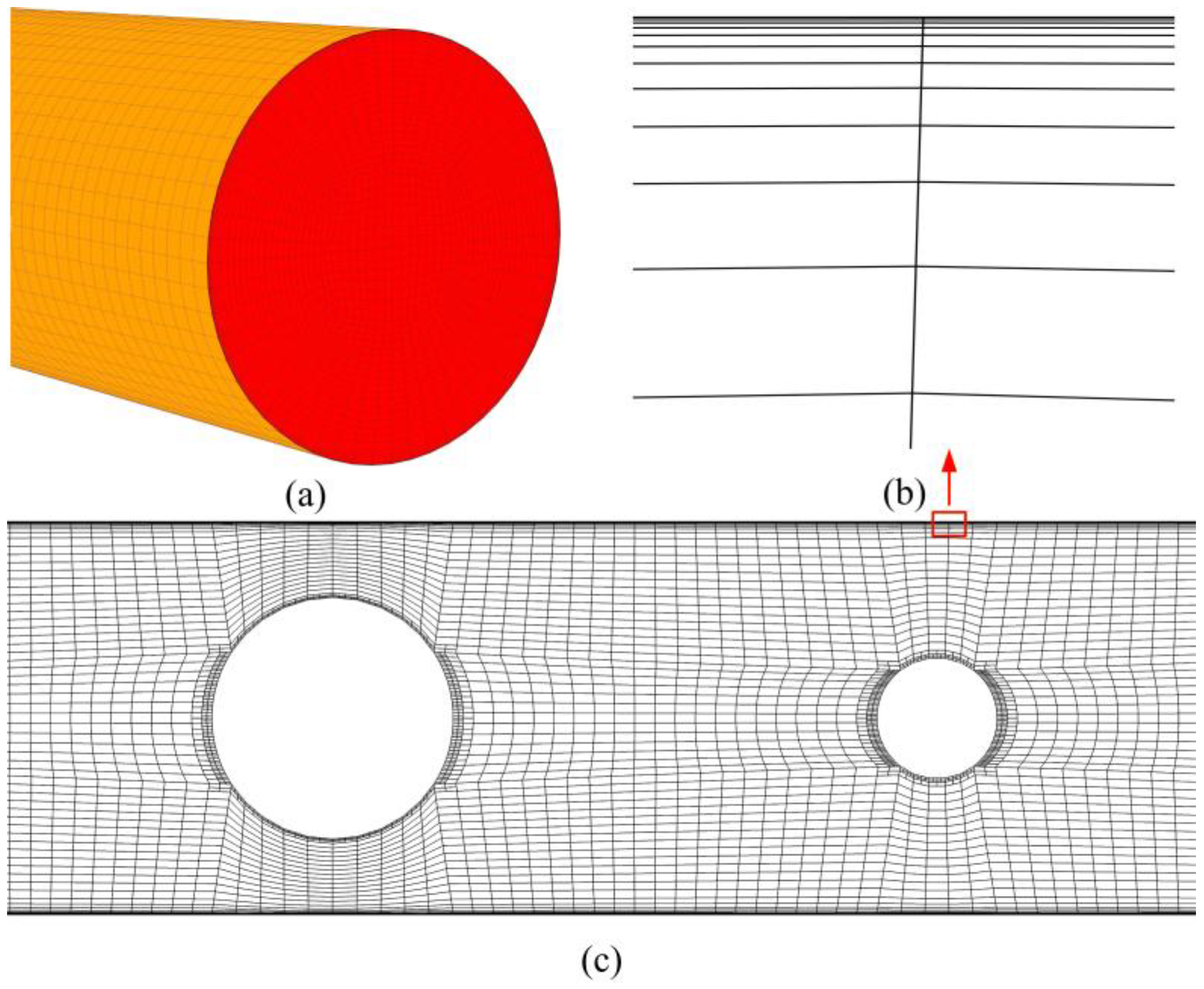
The software ANYSYS ICEM 14.0 was used to generate the meshes, as shown in Figure 2. The mesh was created with a hexagonal grid. The rule of local grid refinement was applied to the boundary layers and adaptive grid refinement was also conducted in this mesh model.
The computational fluid dynamics (CFD) software package, Fluent 14.0 was used for the numerical simulation. All the aforementioned equations accompanied by the specified boundary conditions were evaluated with the finite‒volume method. In the equations, the momentum, turbulent kinetic energy and turbulent dissipation rate were modeled using the second-order upwind scheme. The numerical solution procedure adopted the semi-implicit SIMPLE algorithm. The convergence criterion was set to the relative residuals of all variables, including mass, velocity components, temperature, turbulent kinetic energy, and a turbulent dissipation rate of less than 10−4, except for the energy where a value of 10−7 was used.
2.4. Data Reduction
The Nusselt number and friction factor can be expressed as:
where h is the heat transfer coefficient between the fluid and tube wall, Δp is the pressure drop in the calculated region, um is the mean velocity in the tube.
The Reynolds number can be written as:
To evaluate the effect of heat transfer enhancement at a given pumping power, the performance evaluation criterion (PEC) is defined as:
where and are calculated from the empirical formulas for a plain tube.
3. Results and Discussion
3.1. Validation and Grid Independence Test
To verify the numerical method described above, we compare the computational results of the Nusselt number and friction factor with the well-known empirical formulas for plain tubes, as shown in Figure 3 and Figure 4, respectively. It is clear that the CFD results are in good agreement with the empirical correlations, showing less than 10% and 3.1% deviation for the Nusselt number and friction factor, respectively. The empirical formulas for the plain tube based on the Dittus–Boelter equation and Darcy–Weisbach equation are written as follows [23]:
where Re number is a function of the mean velocity u and the tube diameter D as shown in Equation (15).
Since the solution should be independent from the grids, the grid independent tests were performed by using three different grid cases. The test problem was the turbulent flow in a tube inserted with BTs with BDR = 0.5, 0.75 and 1 at the spacer length of S = 40 mm and Reynolds number of 10,000, as shown in Table 3. From the calculated values, the 1,507,296-, 1,439,776-, and 1,414,464-grid systems were found to be dense enough to be used as the grid independent solutions. Thus, the grid systems with 1,507,296, 1,439,776, and 1,414,464 grids were respectively employed to conduct the subsequent calculations. The grid independent tests were also carried out for other parametric situations.
3.2. Effect of Ball Diameter Ratio
3.2.1. Heat Transfer
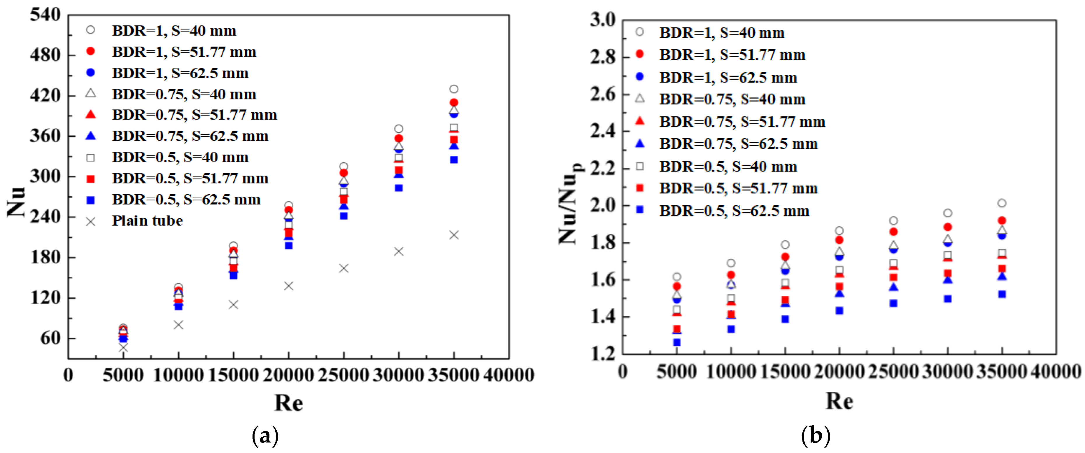
The effects of using the BT with different diameter ratios (BDR = 0.5, 0.75 and 1) on the heat transfer enhancement are shown in Figure 5a,b. At the given Reynolds number, the Nusselt number (heat transfer rate) in the tube equipped with BTs is higher than that in the plain tube for the whole test range. It is also noted that the use of BTs helps enhance the heat transfer rate by about 1.26–2.01 times that of the plain tube. This can be attributed to the thermal boundary layer destruction caused by the BTs.
In addition, the Nusselt number increases with the increase of the Reynolds number because a thinner thermal boundary layer relates to a higher Reynolds number. Since the convective heat transfer can be enhanced more effectively at a higher turbulence level, the effectiveness of heat transfer enhancement is amplified. The numerical results indicate that the BT with a larger ball diameter ratio generates more efficient flow blockage, promoting stronger turbulence intensity to induce a higher heat transfer rate than the BT with a smaller ball diameter. Over the range investigated, the BTs with a ball diameter ratio of BDR = 1 produce the maximum heat transfer rate; that is about 6.8–13.9% and 12.4–23.5% higher than the cases of BDR = 0.75 and 0.5, respectively. Figure 5b indicates that the Nusselt number ratio (Nu/Nup) increases with the increase of the Reynolds number for all BTs.
3.2.2. Friction Factor
How the use of BTs with different ball diameter ratios (BDR = 0.5, 0.75 and 1) impacts on the friction factor is described in Figure 6a,b. Unlike the Nusselt number, the friction factor tends to decrease with the increase of the Reynolds number for all BTs. It is also evident that the use of BTs leads to a substantial increase in the friction factor over that in the plain tube. The increase of the friction factor caused by the BTs is about 3.74–10.27 times that of the plain tube. Moreover, it can be observed that at the given Reynolds number, the friction factor increases with the increase in the ball diameter ratio. This is because at a larger ball diameter ratio, a greater flow interruption tends to increase the shear force and the pressure drop, thereby resulting in a greater flow resistance. It is noteworthy that the BTs with the largest ball diameter ratio, i.e., BDR = 1, mostly yield a larger friction factor with a percentage of 34.6–46.2% and 51.1–63.4% higher than the cases of BDR = 0.75 and 0.5, respectively. This indicates that a smaller ball diameter ratio shows a higher capability to effectively reduce the friction factor. In addition, it is also inferred that the friction factor ratio (f/fp) significantly increases with the increase of the Reynolds number.
3.3. Effect of Spacer Length
3.3.1. Heat Transfer
The effects of the spacer length (S = 40, 51.77, and 62.5 mm) on the heat transfer enhancement are illustrated in Figure 5a,b. Obviously, the value of the heat transfer rate increases with the decrease of spacer length. It can be seen that the BTs with a spacer length of S = 40 mm have the highest heat transfer rate; enhanced by about 1.44–2.01 times that of the plain tube. When S = 51.77 and 62.5 mm, the use of BTs improves the heat transfer performance by approximately 1.34–1.92 and 1.26–1.84 times that of the plain tube. Furthermore, it is also found that the heat transfer enhancement with BTs is intensified with the increase of the Reynolds number. The reason for this result lies in the fact that the BT with a smaller spacer length induces stronger turbulent flow intensity, resulting in better fluid mixing and boundary disturbance. As shown in Figure 7, in the region between the balls, vortices resulting from the occurrence of reverse flows appear. It is also noted that the maximum velocity appears near the wall region instead of the central region. It results in intensification of mixing and improves the heat energy distribution in the whole pipe volume. Comparatively, the BTs with the smallest spacer length (S = 40 mm) improve the heat transfer by 7% and 16% higher than the cases of S = 51.77 and 62.5 mm.
3.3.2. Friction Factor
The influence of the spacer length on the friction factor is shown in Figure 6a,b. Apparently, the friction factor increases with the decrease of spacer length. The BTs with S = 40, 51.77, and 62.5 mm increases the friction factor by around 11.27, 9.98, and 8.99 times that of the plain tube. The reason can be explained by the fact that the BT with a smaller spacer length generates higher dissipation of dynamic pressure of the fluid because of a larger contact surface area. The contours of velocity in the longitudinal sections of the enhanced tube are presented in Figure 7d–f for different spacer lengths, respectively. It can be observed that using a smaller spacer length between the BTs is more effective to frequently disturb the boundary layer, which leads to stronger disturbance upon the fluid. Furthermore, it is noted that the friction factor ratio (f/fp) increases with the increase of the Reynolds number. In addition, the increase in the Nusselt number ratio (Nu/Nup) is significantly higher than the friction factor ratio (f/fp), under certain operating conditions.
3.4. Thermal Performance Factor
The PEC values of the enhanced tube with BTs are illustrated in Figure 8. In all cases, the thermal performance factors are below unity, but the PEC values increase with an increase in the Reynolds number. In general, both the Nusselt number ratio and friction factor ratio increase with the increase of the Reynolds number, as respectively shown in Figure 5b and Figure 6b. However, the effect of the Nusselt number ratio is dominant over the friction factor ratio when a high Reynolds number is used, resulting in the increase of thermal performance factor. Moreover, it is noted that when a smaller spacer length (S = 40 and 51.77 mm) is used, the PEC values for BTs with smaller diameter ratios (BDR = 0.5 and 0.75) is higher than the diameter ratio of BDR = 1. The reason can be explained by the fact that using a smaller spacer length between the BTs is more effective to frequently disturb the boundary layer, which leads to stronger disturbance upon the fluid. This result suggests that it is preferable to use a smaller ball diameter ratio and a smaller spacer length for the design of BTs.
3.5. Flow Characteristics
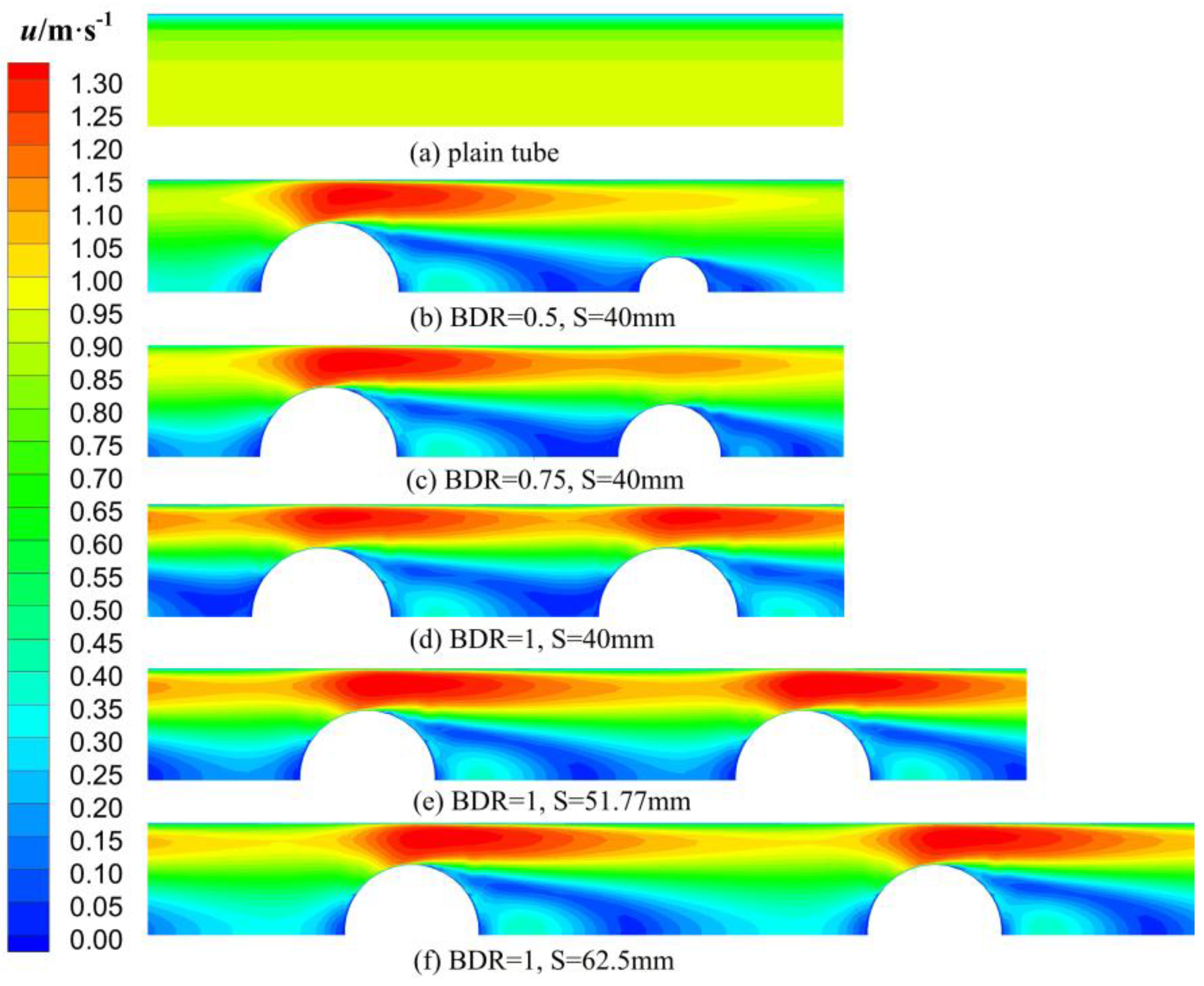
Figure 7 depicts the contours of velocity in the longitudinal sections of the plain tube and enhanced tube with BTs in the case of different ball diameter ratios and spacer lengths at a Reynolds number of 20,000. At the same Reynolds number, it is clear that the flow velocity of fluid near the wall in the tube with BTs is significantly improved, compared with the plain tube. It is also noted that the maximum velocity appears near the wall region instead of the central region. This change increases the velocity gradient in the boundary layer. This effect can periodically induce intense turbulence distribution in the enhanced tube with BTs. Thus, the flow boundary layer is periodically disturbed, which is beneficial to the heat transfer between the fluid and the wall. However, this inevitably leads to a greater flow resistance as well.
Figure 7b–d shows that the boundary layer disturbance is greatly intensified by BTs, and the relevant intensity increases with the increase of the ball diameter ratio. Thus, the flow boundary layer becomes thinner and the friction factor increases at larger ball diameter ratios, as previously shown in Figure 6. At the same time, the heat transfer rate rises as well. The contours of velocity in the longitudinal sections of the enhanced tube are presented in Figure 7d–f for different spacer lengths, respectively. It can be observed that using a smaller spacer length between the BTs is more able to frequently disturb the boundary layer, which leads to a stronger disturbance upon the fluid. Therefore, both the heat transfer rate and flow resistance will decrease with the increase in spacer length.
4. Conclusions
The heat transfer and friction factor characteristics of turbulent water flow in a circular tube fitted with ball turbulators (BTs) at a Reynolds range of 5000–35,000 are investigated through numerical simulation. The effects of BTs with different ball diameter ratios (BDR = 0.5, 0.75, and 1) and spacer lengths (S = 40, 51.77 and 62.5 mm) on the heat transfer rate, friction factor, and thermal performance factor behaviors are investigated under a uniform condition of wall heat flux. The conclusions are listed as follows:
- (1)
- The Nusselt number increases and friction factor decreases as the Reynolds number increases in a tube with BTs. The Nusselt number for an enhanced tube is around 1.26–2.01 times as much as that of the plain tube, while the friction factor sharply increases by approximately 3.74–10.27 times.
- (2)
- It is noteworthy that the BTs with the largest ball diameter ratio of BDR = 1 provide higher friction factors than that of BDR = 0.75 and 0.5 by around 34.6–46.2% and 51.1–63.4%, respectively, showing that a smaller ball diameter ratio is more able to effectively decrease the friction factor.
- (3)
- The PEC values indicate that a smaller ball diameter ratio and a smaller spacer length are preferred. The computational results indicate that when a certain spacer length is used, a larger ball diameter ratio leads to a higher heat transfer rate and with it a higher flow resistance.
- (4)
- From the velocity contours, it is concluded that the flow characteristics are closely related to the use of BTs. The simulation results also show that the flow velocity of fluid near the wall in the tube with BTs is significantly improved, compared with the plain tube, when the same Reynolds number is used.
Author Contributions
W.Y. and G.F. conceived and designed the numerical simulation; G.F., X.Z. and S.Z. performed the simulation and analyzed the data; Z.W. and Y.T. provided the necessary machines and devices; W.Y. wrote the paper.
Acknowledgments
This study is sponsored by the National Natural Science Foundation of China (No. 51722504), Guangdong Science and Technology Planning Project (No. 2017A010104006 and No. 2017KZ010105), and Guangdong Science Fund for Distinguished Young Scholars (No. 2015A030306013).
Conflicts of Interest
The authors declare no conflict of interest.
References
- Liang, C.; Tong, X.; Lei, T.; Li, Z.; Wu, G. Optimal design of an air-to-air heat exchanger with cross-corrugated triangular ducts by using a particle swarm optimization algorithm. Appl. Sci. 2017, 7, 554. [Google Scholar] [CrossRef]
- Bergles, A.E. ExHFT for fourth generation heat transfer technology. Exp. Therm. Fluid Sci. 2002, 26, 335–344. [Google Scholar] [CrossRef]
- Prashant, S.; Jaideep, P.; Srinath, V.E. Characterization of heat transfer enhancement and frictional losses in a two-pass square duct featuring unique combinations of rib turbulators and cylindrical dimples. Int. J. Heat Mass Transf. 2017, 106, 629–947. [Google Scholar]
- Kumar, A.; Prasad, B.N. Investigation of twisted tape inserted solar water heat inserted solar water heaters-heat transfer, friction factor and thermal performance results. Renew. Energy 2000, 19, 379–398. [Google Scholar] [CrossRef]
- Saha, S.K.; Gaitonde, U.N.; Date, A.W. Heat transfer and pressure drop characteristics of laminar flow in a circular tube fitted with regularly spaced twisted-tape elements. Exp. Therm. Fluid Sci. 1989, 2, 310–322. [Google Scholar] [CrossRef]
- Ferroni, P.; Block, R.E.; Todreas, N.E.; Bergles, A.E. Experimental evaluation of pressure drop in round tubes provided with physically separated, multiple, short-length twisted tapes. Exp. Therm. Fluid Sci. 2011, 35, 1357–1369. [Google Scholar] [CrossRef]
- Hong, Y.X.; Deng, X.H.; Zhang, L.S. 3D numerical study on compound heat transfer enhancement of converging-diverging tubes equipped with twin twisted tapes. Chin. J. Chem. Eng. 2012, 20, 589–601. [Google Scholar] [CrossRef]
- Chang, S.W.; Yang, T.L.; Liou, J.S. Heat transfer and pressure drop in tube with broken twisted tape insert. Exp. Therm. Fluid Sci. 2001, 32, 489–501. [Google Scholar] [CrossRef]
- Chang, S.W.; Jan, Y.J.; Liou, J.S. Turbulent heat transfer and pressure drop in tube fitted with serrated twisted tape. Int. J. Therm. Sci. 2007, 46, 506–518. [Google Scholar] [CrossRef]
- Sivashanmugam, P.; Suresh, S. Experimental studies on heat transfer and friction factor characteristics of laminar flow through a circular tube fitted with helical screw-tape inserts. Appl. Therm. Eng. 2006, 26, 1990–1997. [Google Scholar] [CrossRef]
- Sivashanmugam, P.; Suresh, S. Experimental studies on heat transfer and friction factor characteristics of turbulent flow through a circular tube fitted with regularly spaced helical screw-tape inserts. Appl. Therm. Eng. 2007, 27, 1311–1319. [Google Scholar] [CrossRef]
- Naphon, P. Heat transfer and pressure drop in the horizontal double pipes with and without twisted tape insert. Int. Commun. Heat Mass Transf. 2006, 33, 166–175. [Google Scholar] [CrossRef]
- Naphon, P. Effect of coil-wire insert on heat transfer enhancement and pressure drop of the horizontal concentric tubes. Int. Commun. Heat Mass Transf. 2006, 33, 753–763. [Google Scholar] [CrossRef]
- Gunes, S.; Ozceyhan, V.; Buyukalaca, O. The experimental investigation of heat transfer and pressure drop in a tube with coiled wire inserts placed separately from the tube wall. Appl. Therm. Eng. 2010, 30, 1719–1725. [Google Scholar] [CrossRef]
- Zimparov, V. Enhancement of heat transfer by a combination of three-start spirally corrugated tubes with a twisted tape. Int. J. Heat Mass Transf. 2001, 44, 551–574. [Google Scholar] [CrossRef]
- Zimparov, V. Enhancement of heat transfer by a combination of single-start spirally corrugated tubes with a twisted tape. Int. J. Heat Mass Transf. 2002, 25, 535–546. [Google Scholar] [CrossRef]
- Promvonge, P.; Eiamsa-Ard, S. Heat transfer enhancement in a tube with combined conical-nozzle inserts and swirl generator. Energy Convers. Manag. 2006, 47, 2867–2882. [Google Scholar] [CrossRef]
- Promvonge, P.; Eiamsa-Ard, S. Heat transfer behaviors in a tube with combined conical-ring and twisted-tape insert. Int. Commun. Heat Mass Transf. 2007, 34, 849–859. [Google Scholar] [CrossRef]
- Charun, H. Heat transfer and pressure drop in a vertical tube with a nodular turbulizer. Appl. Therm. Eng. 2008, 28, 1984–1994. [Google Scholar] [CrossRef]
- Jasiński, P.B. Numerical study of the thermo-hydraulic characteristics in a circular tube with ball turbulators, Part I: PIV experiments and a pressure drop. Int. J. Heat Mass Transf. 2014, 74, 48–59. [Google Scholar] [CrossRef]
- Jasiński, P.B. Numerical study of the thermo-hydraulic characteristics in a circular tube with ball turbulators, Part II: Heat transfer. Int. J. Heat Mass Trans. 2014, 74, 473–483. [Google Scholar] [CrossRef]
- Jasiński, P.B. Numerical study of thermo-hydraulic characteristics in a circular tube with ball turbulators, Part III: Thermal performance analysis. Int. J. Heat Mass Trans. 2017, 107, 1138–1147. [Google Scholar] [CrossRef]
- Menter, F.R. Review of the shear-stress transport turbulence model experience from an industrial perspective. Int. J. Comput. Fluid Dyn. 2009, 23, 305–316. [Google Scholar] [CrossRef]
Figure 1.
Physical model of a circular tube inserted with ball turbulators (BTs): (a) 3D view; (b) several elements of insert; (c) basic dimensions.
Figure 1.
Physical model of a circular tube inserted with ball turbulators (BTs): (a) 3D view; (b) several elements of insert; (c) basic dimensions.

Figure 2.
Partial computational domain: (a) external grid; (b) grid near the wall; (c) internal grid.
Figure 2.
Partial computational domain: (a) external grid; (b) grid near the wall; (c) internal grid.

Figure 3.
Data verification of the Nusselt number with the Reynolds number for the plain tube.

Figure 4.
Data verification of the friction factor with the Reynolds number for the plain tube.

Figure 5.
The Nussselt number versus the Reynolds number: (a) Nu; and (b) Nu/Nup.

Figure 6.
Friction factor versus Reynolds number: (a) f; and (b) f/fp.

Figure 7.
Velocity contours at Re = 20,000.

Figure 8.
Thermal performance factor versus Reynolds number.


Table 1.
Contents summary of the current literature involving heat transfer and friction characteristics.
Table 1.
Contents summary of the current literature involving heat transfer and friction characteristics.
| Refs. | Method | Research Focus | Conclusions |
|---|---|---|---|
| [5] | Experiment | New twisted tape; decrease the pressure drop; full-length twisted tap | Regularly-spaced twisted tape performed better than the full-length twisted tape; the improved structure could reduce the pressure by 40% |
| [6] | Experiment | Multiple short-length twisted tapes; decrease the pressure drop | Yielded at least a 50% pressure drop compared with that of the full-length twisted tapes |
| [7,8,9,10,11] | Experiment | Other modified patterns; improve the overall thermo-hydrodynamic performance | Improving the overall thermo-hydrodynamic performance of the tubes fitted with twisted tapes |
| [12,13,14] | Experiment | Heat transfer and pressure drop; coil-wire inserts | The use of coiled wire inserts led to significant increases in both heat transfer and pressure drop |
| [15,16,17,18] | Experiment | Combine different techniques; enhanced heat transfer | Coupled methods are more able to enhance the heat transfer process as well as increase the friction factor than the use of a single method |
| [19,20,21,22] | Numerical methods | A new type of insert; ball turbulator (BT) | Heat augmentation was achieved at the cost of a higher pressure drop |
| This study | Numerical simulation | A new kind of BT; optimize the heat transfer performance | The Nusselt number increases and friction factor decreases as the Reynolds number increases; smaller ball diameter ratio is more able to effectively decrease the friction factor; larger ball diameter ratio leads to a higher heat transfer rate |
Table 2.
Geometric parameters of the BTs.
| Ds (mm) | Db (mm) | BDR | S (mm) |
|---|---|---|---|
| 8 | 16 | 0.5 | 40 |
| 8 | 16 | 0.5 | 51.77 |
| 8 | 16 | 0.5 | 62.5 |
| 12 | 16 | 0.75 | 40 |
| 12 | 16 | 0.75 | 51.77 |
| 12 | 16 | 0.75 | 62.5 |
| 16 | 16 | 1 | 40 |
| 16 | 16 | 1 | 51.77 |
| 16 | 16 | 1 | 62.5 |
Table 3.
Variation for the independency of solutions on grid systems at Re = 10,000.
| Case | Size of Grid | Nu | f |
|---|---|---|---|
| BDR = 0.5, S = 40 mm | 1,507,296 | 119.0010 | 0.2223 |
| 1,665,452 | 120.6928 | 0.2237 | |
| 2,208,640 | 120.7506 | 0.2231 | |
| BDR = 0.75, S = 40 mm | 1,439,776 | 126.1883 | 0.2571 |
| 1,534,488 | 126.4668 | 0.2551 | |
| 2,207,128 | 126.4893 | 0.2550 | |
| BDR = 1, S = 40 mm | 1,414,464 | 136.9326 | 0.3503 |
| 1,681,248 | 136.9486 | 0.3485 | |
| 2,129,344 | 137.4344 | 0.3433 |
© 2018 by the authors. Licensee MDPI, Basel, Switzerland. This article is an open access article distributed under the terms and conditions of the Creative Commons Attribution (CC BY) license (http://creativecommons.org/licenses/by/4.0/).
Share and Cite
MDPI and ACS Style
Yuan, W.; Fang, G.; Zhang, X.; Tang, Y.; Wan, Z.; Zhang, S. Heat Transfer and Friction Characteristics of Turbulent Flow through a Circular Tube with Ball Turbulators. Appl. Sci. 2018, 8, 776. https://doi.org/10.3390/app8050776
AMA Style
Yuan W, Fang G, Zhang X, Tang Y, Wan Z, Zhang S. Heat Transfer and Friction Characteristics of Turbulent Flow through a Circular Tube with Ball Turbulators. Applied Sciences. 2018; 8(5):776. https://doi.org/10.3390/app8050776
Chicago/Turabian StyleYuan, Wei, Guoyun Fang, Xiaoqing Zhang, Yong Tang, Zhenping Wan, and Shiwei Zhang. 2018. "Heat Transfer and Friction Characteristics of Turbulent Flow through a Circular Tube with Ball Turbulators" Applied Sciences 8, no. 5: 776. https://doi.org/10.3390/app8050776
Note that from the first issue of 2016, this journal uses article numbers instead of page numbers. See further details here.