Article

A Fuzzy Path Selection Strategy for Aircraft Landing on a Carrier

1
Department of Airborne Vehicle Engineering, Naval Aviation University, Yantai 264001, China
2
College of Aerospace Engineering, Chongqing University, Chongqing 400044, China
3
System Engineering Research Institute, China State Shipbuilding Corporation, Beijing 10094, China
*
Author to whom correspondence should be addressed.
Appl. Sci. 2018, 8(5), 779; https://doi.org/10.3390/app8050779
Submission received: 15 April 2018 / Revised: 2 May 2018 / Accepted: 11 May 2018 / Published: 14 May 2018

Abstract

:
Landing is one of the most dangerous tasks in all the operations on an aircraft carrier, and the landing safety is very important to the pilot and the flight deck operation. Nowadays, the landing safety of carrier aircraft is improved by designing an automatic landing controller and by training the pilot to increase his/her control ability. However, the importance of choosing the landing path has not been investigated thus far. In this paper, the problem of landing path selection for an aircraft carrier is studied as there are several candidates corresponding to different situations. A fuzzy path selection strategy is proposed to solve the problem considering the fuzziness of environmental information and human judgment, and the goal is to provide the pilot with a more reasonable decision. The strategy is in view of the idea of Fuzzy Multi-attribute Group Decision Making (FMAGDM), which has been widely used in industry. Firstly, the background of the landing path selection is given. Then, the factors influencing the decision making are abstracted to build the conceptual model. A TOPSIS-based group decision-making method is developed to denote the preference of each decision maker for each alternative route, and the optimal landing path under the current environment is determined taking into account the knowledge and the weight of both the pilot and the landing console operator (LCO). Experimental studies under different setups, i.e., different environments, are carried out. The results demonstrate that the proposed path selection strategy is validated in different environments, and the optimal landing paths corresponding to different environments can be determined.

1. Introduction

Aircraft landing on a carrier is a task with high risk [1]. An aircraft can land on a carrier successfully with a probability of 70%, and the rate is lower at night. In comparison with land-based aircraft, landing on an aircraft carrier is more dangerous and complicated since a series of particular conditions needs to be taken into account. In addition, the flight condition and the maritime environment are changing all the time, and these uncertainties make the landing task difficult [2,3]. In order to guide the aircraft landing safely, an aircraft carrier must be equipped with certain special guidance devices such as a Fresnel lens optical landing system [4], an all-weather radar landing system [5] and so on. Further, a variety of commanders and staff are needed to guarantee the landing safety of aircraft and cope with all emergencies [6]. Among them, the landing console operator (LCO) onboard is responsible for supervising the aircraft, which is about 20 nautical miles away from the aircraft carrier. The landing signal officer (LSO) concentrates on the last step of landing and he/she assists the pilot to land safely using body language or by talking to the pilot directly [7]. The air officer in the control tower does the work related to the flight deck, e.g., preparing the flight deck for launching, managing the aircraft on the flight deck and emptying the flight deck for landing. Each staff member mentioned above assumes their own duty at different stages of landing, and the safe landing of aircraft is accomplished by their team work.
In each landing stage, the above commanders and staff make a decision to guide the aircraft in a very short time based on their knowledge and the information shown on various instruments, which makes high-level demands on their judgment and reaction [8]. However, there is fuzziness in the environment and flight information, and accurate judgment cannot always be reached quickly, which is attributed to the complicacy and variability of weather at sea, the lack of comprehensive information and other subjective factors. In recent years, artificial intelligence (AI) has been widely applied to various fields, and many great achievements have been made in this field. For instance, the complex changes and uncertainties in manufacturing can be managed by AI and machine learning techniques [9]. Another case in point is the routing problems for ground vehicles, and minimal total cost can be achieved using AI without violating the capacity and time window constraints [10]. As the AI-based methods have shown better performance than humans in ranking the candidates [11] and optimizing the index [12], these methods are expected to be introduced into the decision-making system of the aircraft carrier to reduce the workload of the staff onboard and to improve the safety level of the landing.
Currently, the studies on the landing of aircraft concentrate primarily on the last step, i.e., the design of an automatic landing controller and the interaction between the pilot and the LSO. For example, the landing safety is analyzed based on rough set theory, and the values of kinematic parameters and their combinations are determined to define the boundary conditions for safe landing [13]. The action of the LSO is described by a fuzzy language, and multiple AI techniques are applied to the landing decision-support tool. The obtained landing decision-support tool allows the LSO to make better time-critical decisions in a dangerous environment [14]. The gesture of the LSO is also studied extensively, and a multi-signal gesture database, which requires both body knowledge and hand knowledge of the LSO to distinguish gestures, was introduced. Subsequently, the true meaning of gestures obtained based on the gesture database is communicated to the pilot to enable a better understanding and to assist landing [15]. Our team also conducted intensive research on the automatic landing guidance technology. A model of LSO was found for the digital simulation of a pilot-carrier system on the basis of analyzing the behaviors of LSO in the final stage of landing. Fuzzy logic laws were used to model three kinds of behaviors of the LSO. Afterwards, the carrier motion prediction of the LSO was described by a neural network model, and the model was verified by simulating landing under several kinds of conditions [16]. In the aspect of studying pilot behavior, a variable-strategy pilot model was established for landing. This model is comprised of two switchable components: a discrete component of the acquisition strategy for a large deviation of the glide path and a continuous component of the pursuit tracking strategy for a small deviation [17]. The cited literature can explain the work of LSO, and mathematical models are established to describe the LSO’s action. The above studies regarding the landing process of the carrier aircraft presented solid research work on the automatic landing guidance technology and have potential significance in the landing safety of aircraft. The issue of the landing path for aircraft carrier is also an important part of the automatic landing guidance technology. Unlike the unmanned aerial vehicle (UAV) path planning problem [18], the landing path of manned aircraft is fixed and can only be selected from several candidates. Therefore, instead of planning the landing path, it is determined before the aircraft is ready to reach the carrier, and the landing path determination is also a part of the LCO’s work [19,20]. However, no relevant literature has been reported on this issue so far. Besides, the previous methods, such as the proposed method in Ref. [14,17], are related to the behavior of the LSO and the pilot, and the goal is to reduce the error between the ideal and actual landing path as much as possible. The premise of those methods is that the landing path has been determined, and a new method has to be developed to solve the landing path selection problem. As the landing path selection is the first step to guide the aircraft landing, it is important to the whole process of the landing task and thus is worthwhile to be studied intensively.
At present, the landing path of carrier aircraft is determined by the LCO’s experience, and then the decision is sent to the pilot. The pilot is passive in the process of determining the landing path, which is not so reasonable because the pilot also has some important information and should have the right to make a suggestion on the selection of the landing path. Besides, the experience of the LCO is not always reliable, especially in complicated situations, and some unreasonable decisions may be made if only the knowledge and experience of a human are depended on. Therefore, a landing path selection strategy is imperative to deal with the above defects, thus reducing the workload and ensuring the landing safety. The decision should be made according to the performance of the aircraft, the traffic conditions, a variety of weather conditions and the visibility of the pilot, and fuzziness is involved in the landing path selection problem [21].
The main contribution is to establish a mathematical model and provide a method to solve the landing path selection problem. This problem is a sort of decision-making problem which belongs to the air traffic management of the carrier. To make a subjective judgment optimal and practical, a decision needs to be made based on reliable information considering all constraints. Obtaining the environmental information quickly is essential to the decision-making process in this problem. Moreover, how to process information according to knowledge and experience is the key. The problem involves various elements and fuzzy information. Therefore, it is an unstructured decision-making problem. This kind of problem can only be solved based on the experience and flexibility of a decision maker or using an AI method. It is also worth noting that different decision makers may result in different judgments due to many reasons. For example, they obtain different information, they are assigned different flight tasks and objectives, or they have a different understanding of performance criteria. Considering all the above-mentioned factors, this paper introduces a group decision-making scheme based on the TOPSIS (Technique for Order Preference by Similarity to an Ideal Solution) approach, which is an effective method to coordinate the above differences to result in a reasonable decision.

2. Problem Statement and Conceptual Model Establishment

In this section, the landing path selection problem will be described firstly, and then the essential elements involved in the problem are discussed. A brief conceptual model is given at the end of this section to provide an overview for solving this problem.

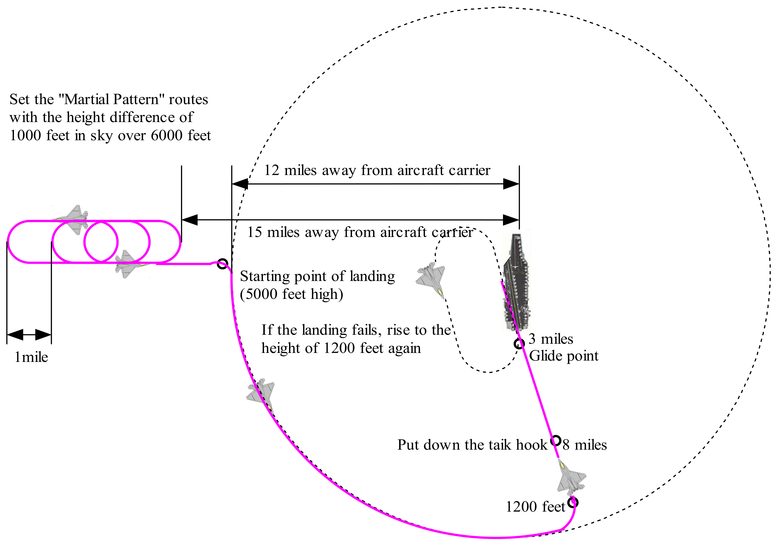
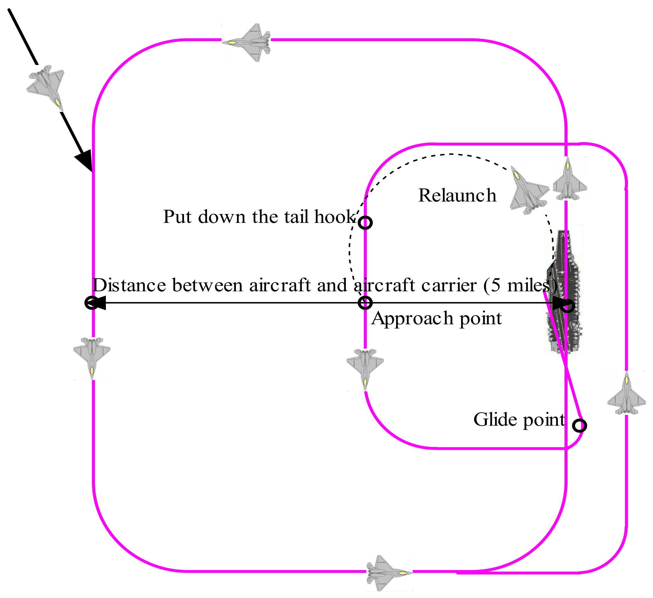
2.1. Problem Statement

According to the tactical imperatives, an aircraft receives returning information from the air control system on the carrier. To ensure the safety of returning flight, the real-time position information is provided by the Tactical Air Navigation (TACAN), which contains the relative position of the carrier. The returning aircraft is also instructed by an airborne early warning (AEW) system, which provides the returning aircraft with the overall air traffic situation. The information from an AEW is essential when managing the landing paths for a large amount of airplanes in order to guarantee a safe and orderly landing. The sea weather is obtained from the carrier and is transmitted to the pilot. To sum up, the landing path selection problem is a process in which the pilot and the LCO combine/analyze various information and then make quick decision accordingly. The details of the problem are shown in Figure 1.
The dotted line in Figure 1 shows that when the pilot selects the optimal landing path, he/she treats the weather information as a reference instead of relying on it to make a judgment. This is because the weather information is relative to the carrier, and there may be differences between the places around the aircraft and around the carrier. This explains why the pilot merely regards the weather information from an observatory as a reference.
In Figure 1, the pilot and the LCO are the two decision makers regarding the optimal landing path. The LCO is the major decision maker because he/she has more information on the air traffic condition. Furthermore, the feeling of a pilot is considered limited although he/she has a comprehensive understanding of the weather information and the performance of the aircraft. The reason is as follows. In actual work, the pilot usually has a heavy workload, e.g., executing a flight mission and analyzing various information simultaneously; therefore, he/she will be distracted from other work and his/her judgment will be affected accordingly.

2.2. Essential Elements

According to the problem description, there are several essential elements in the path section problem: the decision makers, the alternative landing paths and the contributing factors. The decision makers have been analyzed above, the remaining two are depicted later.
  • The alternative landing paths:
Four landing path are regulated according to the atmospheric environment, the performance of the aircraft and the air traffic condition, as listed below.
1)  l 1 : The weather, visibility, performance of aircraft and air traffic are suitable for landing.
Under such conditions, the pilot lands the aircraft by vision. The aircraft flies counterclockwise following the rectangular route above the carrier, as shown in Figure 2.
The carrier is located in the center of the right edge of the rectangle at this moment. If the aircraft keeps waiting for the landing command, it will fly counterclockwise following the rectangular path and will get in touch with the approaching operation person every time it passes the carrier to confirm the landing permission.
2)  l 2 : The weather and visibility are both at a medium level, and the performance of the aircraft and the air traffic are suitable for landing.
A safer landing path will be used when clouds appear between the height of 1000 and 3000 feet and cover more than 5/8 of the sky. It is dangerous for the pilot to land the aircraft by vision in this case due to the heaviness of clouds. Therefore, a landing path called “Martial Pattern” is set 15 miles away from the carrier to guarantee the landing safety, as shown in Figure 3. The aircraft will repeat the “Martial Pattern” until it is permitted to land.
3)  l 3 : The weather and the visibility are both bad, but the performance of the aircraft and the air traffic are suitable for landing.
It is also unsafe for the pilot to land the aircraft by vision under such conditions. Similarly, the “Martial Pattern” is set 15 miles away from the carrier, and the aircraft repeats the “Martial Pattern” before being permitted to land, as shown in Figure 4. Unlike in the case of l 2 , the aircraft does not have to fly a rectangular route around the carrier after receiving the landing permission. Instead, it approaches the carrier directly by gliding.
4)  l 4 : Poor performance of aircraft or bad air traffic condition.
In this case, as it is dangerous to land on the carrier, the pilot has to get in touch with the staff on land for an emergency landing.
2.
The contributing factors:
1) Weather
It is often difficult to predict the sea weather because no obstacles exist above the sea, and the air flow above the sea is active. Therefore, the weather information is obtained by measuring the nearby weather condition continuously. Usually, l 1   l 2 and l 3 are chosen for good, medium and bad weather, respectively.
2) Height of clouds
Low clouds which cover a wide range of the sky will impair the vision of the pilot. Therefore l 1 is preferred when there are few or no clouds. Otherwise, l 2 or l 3 , which allow a higher safety standard, are preferred.
3) Visibility
The visibility of the pilot will have an influence on the accuracy of landing. Good visibility often leads to the choice of l 1 or l 2 . On the contrary, l 3 or even l 4 will usually be chosen under poor visibility.
4) Performance of the aircraft
In daily training and scouting tasks, the aircraft is normally in good operating condition and will land on the carrier according to the command received. However, the aircraft may be damaged when accidents occur, and l 4 will be the best choice in this case to guarantee the landing safety.
5) Air traffic
This refers to the flyable space for the landing aircraft. If the air traffic indicates crowded conditions or the returning schedule fails, l 4 provides a safe landing solution.

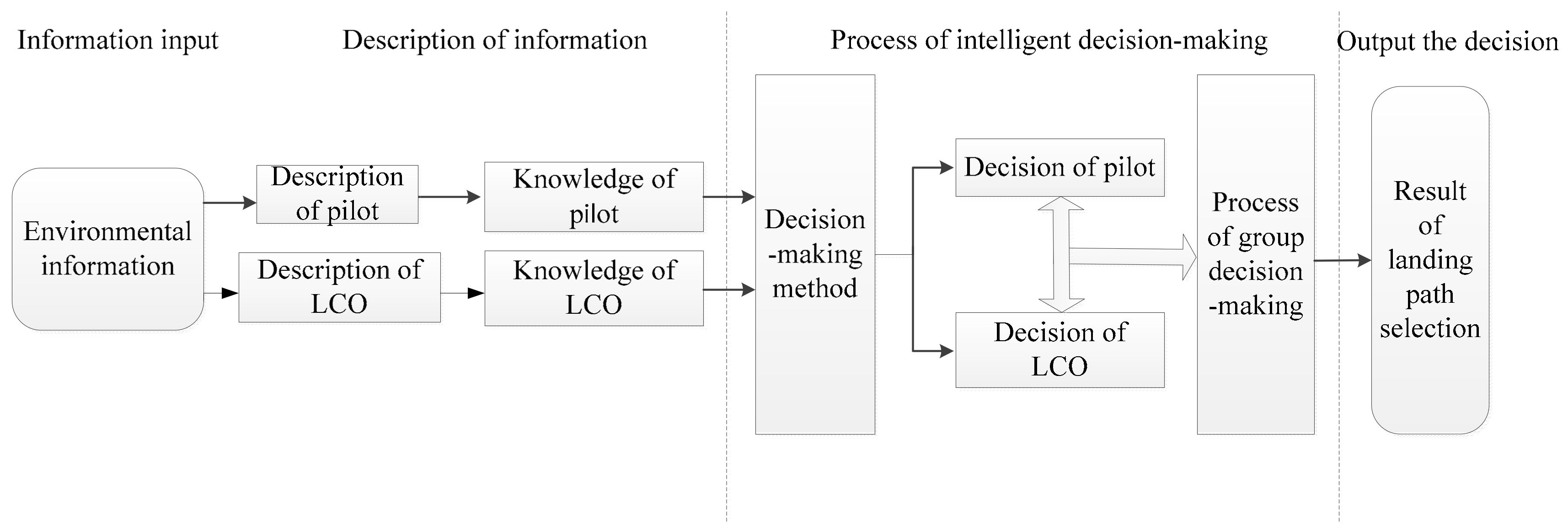
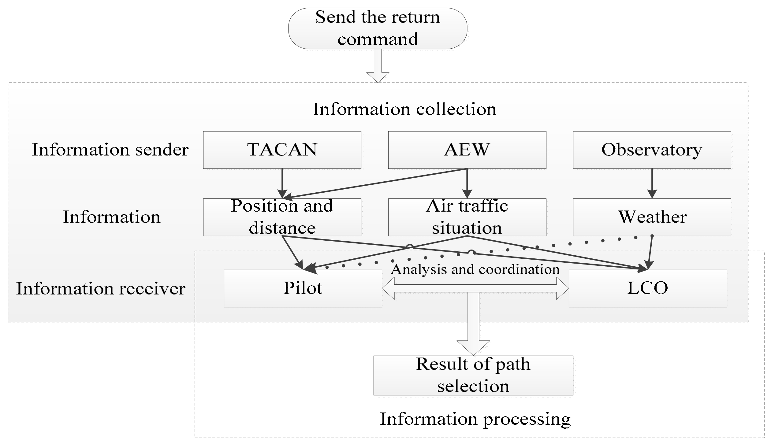
2.3. The Conceptual Model

Based on the description of the landing path selection problem and the analysis of its essential elements, the key components involved in the problem are abstracted, and a conceptual model is established (see Figure 5) to provide the reader a general idea of decision-making when solving this problem.

3. Landing Path Selection Method Based on FMAGDM

To solve the landing path selection problem, mathematical descriptions of the essential elements are needed to establish the model. Since it is difficult to describe the real-time environmental information quantitatively, the judgment of a single pilot or a single LCO is often inaccurate. Therefore, it is necessary to develop a comprehensive decision-making method which integrates the judgments of both the pilot and the LCO to make the final decision more scientific and reasonable. In view of the abovementioned characteristics, the FMAGDM method can describe the information pertaining to the environment and the weights of decision-makers [22,23,24] and is suitable for solving the path selection problem. To be specific, the fuzzy TOPSIS approach [25,26] is developed, and the triangular membership function is applied to denote the PRCF (performance ratings of contributing factors) and the current environmental vector. Then, the mathematical model is built to evaluate alternative landing paths. To combine the decisions of the pilot and the LCO, the group decision-making method based on the TOPSIS approach is developed to rank the alternative landing paths. Finally, the optimal landing path under the current environment is obtained.

3.1. The PRCF and the Current Environmental Vector

In the process of building a decision-making model, the PRCF or the current environmental vector is described by the fuzzy linguistic variables in this study. In this problem, each candidate landing path corresponds to an ideal environmental vector, and the triangular membership function is fit for this characteristic and is used to define the value of each fuzzy linguistic variable. For example, “low”, “medium” or “high” is used to express the performance rating of l 1 with respect to the weather, and the triangular membership function is used to define “low”, “medium” or “high”. Therefore, the triangular membership function is the foundation of establishing the decision-making model. The concept and attributes of the triangular membership function are given below to ensure a better understanding of its application in the path selection problem [27].
Definition 1.
Let a = [ a L , a M , a U ] be a triangular membership function with 0 < a L a M a U , as shown in Figure 6.
An example is presented to provide a clear understanding of its function in describing the current environmental vector. Assume that a is a triangular membership function to describe good visibility of pilot. The plots indicate that the possibility of this case, i.e., current visibility is good, increases from point B to point A and reaches the maximum at point A. On the contrary, the possibility decreases from point A to point C and reaches the minimum at point C.
Definition 2.
The mean value of the triangular membership function is defined as
s ( a ) = ( a L + 2 a M + a U ) / 4
This definition is used to rank the triangular membership functions. Assume that a and b are two triangular membership functions; the following are defined: a b if s ( a ) s ( b ) and a < b if s ( a ) < s ( b ) . For example, if a and b describe different performances of an aircraft, a b indicates that the performance described by a is generally better than that described by b.
Definition 3.
Assume that U is a universe of discourse, and the α -cut set (denoted by a α ) is defined as
a α = { x U | μ λ ( x ) α } , α [ 0 , 1 ]
where a α can be further expressed as a α = [ a L ( α ) , a R ( α ) ] , as illustrated in Figure 7. If it presents moderate weather, a α indicates that the degree of moderate weather is more than that of α .
Definition 4.
If a b (a and b are two triangular membership functions and can be denoted as a = [ a L , a M , a U ] and b = [ b L , b M , b U ] ), and the fuzzy distance between them can be defined as
d ( a , b ) = [ max { 0 1 d L ( α ) d α , 0 } , d L ( 1 ) , 0 1 d R ( α ) d α ]
where d L ( α ) and d R ( α ) are written as
{ d L ( α ) = a L ( α ) b R ( α ) d R ( α ) = a R ( α ) b L ( α )
Similar to the definition of distance in a geometric space, the fuzzy distance also represents the degree of approximation between these two triangular membership functions. For example, suppose that a and b describe good and bad air traffic situations, respectively; then, d ( a , b ) represents how large the difference is between these two air traffic conditions. It should be noted that d ( a , b ) is also a triangular membership function.
Until now, knowledge of the triangular membership function to describe the fuzzy linguistic variables when establishing a decision-making model has been presented. Some main operations associated with triangular membership functions are listed below (a and b are two random triangular membership functions, k is a random real number):
a + b = [ a L , a M , a U ] + [ b L , b M , b U ] = [ a L + b L , a M + b M , a U + b U ] ;
a × b = [ a L , a M , a U ] × [ b L , b M , b U ] = [ a L × b L , a M × b M , a U × b U ] ;
k × a = [ k × a L , k × a M , k × a U ] ;
a 1 = [ 1 / a U , 1 / a M , 1 / a L ] .

3.2. Landing Path Selection Process Based on the Fuzzy TOPSIS Approach

The weather condition, the height of clouds, the visibility, the performance of the aircraft and the air traffic condition are the five key contributing factors determining the result of the landing path selection and can be written as f 1 , f 2 , f 3 , f 4 and f 5 , respectively. The PRCF are described by triangular membership functions and need to be unified into the same linguistic variables. Among the five contributing factors, only the performance ratings of cloud height and visibility can be described quantitatively, as shown in Table 1 and Table 2.
Note that the linguistic variables listed in Table 2 are described by the triangular membership functions. Assume that the performance rating of l j ( j = 1 , 2 , 3 , 4 ) with respect to f i ( i = 1 , 2 , 3 , 4 , 5 ) is e i j = [ e i j L , e i j M , e i j U ] (the value of e i j can be chosen from Table 2); the fuzzy decision matrix of the path selection problem can be written as
D = [ e 11 e 12 e 13 e 14 e 21 e 22 e 23 e 24 e 51 e 52 e 54 ]
where matrix D is the base of priori knowledge of the decision makers.
Having introduced the basics of the developed fuzzy TOPSIS approach for solving the path selection related decision making problem, the detailed procedure will be described below.
Step 1: Normalization of the fuzzy decision matrix
When the raw data are collected, different measurement units are used by contributing factors, e.g., the descriptions of f 2 and f 3 , so normalization is needed to transform each element of D into the interval of [0, 1] to eliminate anomalies. Here, a linear transformation is used to calculate the normalized fuzzy decision matrix X:
X = [ x 11 x 12 x 13 x 14 x 21 x 22 x 23 x 24 x 51 x 52 x 54 ]
As the PRCF denote the efficiency in the path selection problem, x i j is normalized using its largest value:
x i j = [ e i j L / e i U max , e i j M / e i U max , e i j U / e i U max ]
where e i U max = max 1 j 4 { e i j U } ( i = 1 , 2 , ... , 5 , j = 1 , 2 , 3 , 4 ) . All linguistic variables can be transformed to the interval of [0, 1] by the same method used in Equation (11).
Assume that the pilot and the LCO are decision makers No. 1 and No. 2, respectively, and the normalized fuzzy decision matrix X 1 and X 2 can be obtained according to prior knowledge of them.
X 1 = [ H I M E L O N O V H H I L O N O V H V H L O L O M E H I H I L O M E H I H I L O ] , X 2 = [ H I M E N O N O H I M E L O N O H I H I L O N O M E H I H I M E H I V H V H L O ]
Comparing X 1 with X 2 , it can be found that the performance ratings of a pilot are higher than those of the LCO with respect to the atmospheric environment in general. This is because the pilot has an accurate sense of the atmospheric environment, and he/she is usually conservative for safety reasons when determining the landing path. Higher performance ratings with respect to the air traffic situation are set higher by the LCO compared to the pilot. This is because the LCO grasps comprehensive traffic information, and he/she puts higher priority on the safety operation of the carrier.
Step 2: Integration of the current environmental vector into X1 and X2
The environmental vector for the case under consideration can also be described by the linguistic variable, as listed in Table 3.
Assume that the environmental evaluation of each contributing factor is ω i = [ ω L , ω M , ω U ] ( i = 1 , 2 , ... , 5 ); the value of ω i is chosen from Table 3. After integrating the environmental vector, the normalized fuzzy decision matrix can be written as follows:
Z = ( z i j ) 5 × 4 = ( ω i x i j ) 5 × 4 = [ z 11 z 12 z 13 z 14 z 21 z 22 z 23 z 24 z 51 z 52 z 54 ]
Step 3: Determination of the ideal solutions
The ideal solutions refer to the fuzzy positive ideal reference point (FPIRP) and negative point (FNIRP) and are written as P and N for convenience. P is obtained when each PRCF chooses its highest value from the fuzzy decision matrix D, and similarly N is obtained by choosing the lowest value for each performance rating. Therefore, P and N can be denoted as P = ( p 1 , p 2 , ... , p 5 ) and N = ( n 1 , n 2 , ... , n 5 ) with p i = max 1 j 4 { z i j } and n i = min 1 j 4 { z i j } . These solutions are called the ideal solutions because the corresponding cases are almost impossible to happen in reality.
Step 4: Calculation of the fuzzy distance between l j ( j = 1 , 2 , ... , 4 ) and the ideal solution
The fuzzy distance is defined as follows using Equation (3):
d ( l j , P ) = i = 1 5 d ( z i j , p i )
d ( l j , N ) = i = 1 5 d ( z i j , n i )
The optimal landing path is the one which is close to the FPIRP and far away from the FNIRP. According to different distances from the FPIRP, the ranking of all the alternative landing paths can be determined.
Step 5: Calculation of the closeness coefficient
The closeness coefficient denotes the degree of closeness between the alternative landing path and the fuzzy ideal solution, and a high value means a closer degree. The following formula is used to calculate the closeness coefficient.
C ( l j ) = μ d ( l j , P ) d ( l j , P ) + d ( l j , N ) + ( 1 μ ) d ( l j , N ) d ( l j , P ) + d ( l j , N )
where μ ( 0 < μ < 1 ) is a variable parameter which denotes the weight of different distances from FPIRP and FNIRP, and it can be adjusted by the bias of the decision maker. For example, if the atmospheric environment is good in general, the decision maker usually puts more attention on FPIRP and sets μ as a smaller value. A larger value will be set for μ to put more attention on FNIRP if the air traffic situation is bad.

3.3. Process of the Group Decision-Making

The decision of a pilot or an LCO can be calculated separately according to the above mentioned procedure. In reality, a decision made by one of them may not be the optimal solution because different decision makers obtain different information and have difference in knowledge and preference. Therefore, to deal with the divergence and to make an optimal decision, the decision of both the pilot and the LCO should be integrated. The group decision-making problem will be discussed and addressed in this section.
To solve this group decision-making problem, the pilot and the LCO are regarded as two contributing factors, and the problem is then translated into a decision-making problem by a single person [28]. The fuzzy decision matrix for group decision making is established below:
O = [ o 11 o 12 o 14 o 21 o 22 o 24 ] .
where o s t ( s = 1 , 2 ; t = 1 , 2 , 3 , 4 ) is the closeness coefficient C ( l j ) calculated for each decision maker by Equation (15). The process of group decision making is depicted in detail in four steps:
Step 1: The matrix O is a normalized fuzzy decision matrix, so the normalization step can be skipped. We assume the weights of pilot and LCO as λ 1 = [ λ 1 L , λ 1 M , λ 1 U ] and λ 2 = [ λ 2 L , λ 2 M , λ 2 U ] , respectively. The weighted normalized group fuzzy decision matrix can be calculated in the same way as in Section 3.2 and is expressed as V = ( v k j ) 2 × 4 ( k = 1 , 2 ; j = 1 , 2 , 3 , 4 ) . Note that the decison of the LCO should be granted greater weight due to the fact that the LCO is less subject to many kinds of distraction compared to a pilot. On the other hand, the opinion of the pilot should be also taken into account since he/she has a better feeling in weather and better knows the current aircraft performance.
Step 2: Determine GP and GN (the fuzzy positive group ideal reference point (FPGIRP) and negative point (FNGIRP)). FPGIRP and FNGIRP can be denoted as G P = ( g p 1 , g p 2 ) and G N = ( g n 1 , g n 2 ) ( g p k = max 1 j 4 { v k j } and g n k = min 1 j 4 { v k j } ).
Step 3: Calculate the fuzzy distance and the closeness coefficient.
d ( l j , G P ) = k = 1 2 d ( v k j , g p k )
d ( l j , G N ) = k = 1 2 d ( v k j , g n k )
G C ( l j ) = η d ( l j , G P ) d ( l j , G P ) + d ( l j , G N ) + ( 1 η ) d ( l j , G N ) d ( l j , G P ) + d ( l j , G N )
where η ( 0 < η < 1 ) can also be adjusted to denote the different importance of FPGIRP and FNGIRP. Therefore, the principle of choosing η is similar to that of μ .
Step 4: Obtain the mean value s ( G C ( l j ) ) using Equation (1), and the landing path corresponding to max 1 j 4 { s ( G C ( l j ) ) } is the optimal one in the current environment. The ranking of alterative paths can be calculated in the meantime. Note that the final decision has to be close to that of both decision makers.

4. Experimental Study on Landing Path Selection in Different Environments

In this section, experiments are conducted to investigate the effectiveness of the proposed path selection strategy. Four different environmental conditions are set as test scenarios. In each test scenario, two methods, i.e., the experience-based method by LCO and the proposed method, are both used to solve the landing path selection problem. Comparisons between the two methods are carried out to verify the advantage of the proposed method.

4.1. Simulation Conditions and the Fuzzy Descriptions of Contributing Factors

The performance ratings and environmental evaluations are illustrated in Table 4.
Note that in Table 4, each element of the environmental vector uses the same triangular function because the characteristic of each element is similar and the same form of triangular function is convenient for computing. The form of the triangular function is determined by trial and error to get good results. Different environments are set to validate the rationality of the proposed method, and from case i to case iv, the environmental setting is degrading gradually. The environmental settings and evaluations of the LCO and the pilot are given in Table 5 and Table 6, respectively.

4.2. Results with the Experience-based Method by the LCO

The landing path under four different environments is determined by the experience of the LCO in this section. Ten experts working on the control center of the carrier are invited to give their answers of the best landing paths under the four different environments. After a brief visit with the ten experts, their experience in determining the optimal landing path can be summarized as shown in Figure 8.
Based on the experience of the LCO, the results of the landing path selection are shown in Table 7. Note that the numbers in Table 7 denote the number of LCOs choosing the corresponding landing path as the best.
The numbers in bold mean that most LCOs regard the corresponding landing path as the best choice. In general, the results of the landing path selection by LCOs conform to their experience listed in Figure 8. More discussion and comparison will be conducted after the same problem is solved by the proposed method in the next section.

4.3. Results of Landing Path Selection by the Proposed Method and the Discussion

In this section, the proposed landing path selection strategy is used to determine the optimal landing path under four different validating environments. The results are listed in Table 8, Table 9, Table 10 and Table 11. For each test case, the optimal landing path and the ranking of the four alterative paths are given.
From case i to case iv, with the changes of the environmental setups, the path selection strategy is able to determine the optimal landing path for each validation case. Note that l 4 always ranks in the last place when the environmental condition is generally good for the aircraft landing. It demonstrates that the pilot will not land the aircraft on the ground unless the situation is too bad.
Compared to the results obtained by the LCO’s experience, the same optimal landing path is selected in case ii and case iv, while in case i, l2 and l1 are regarded as the best choice by the LCO’s experience and the path selection strategy, respectively. In this case, the condition is good in general, and the two LCOs’ decision is the same as the path selection strategy. However, the majority of LCOs make a conservative decision and l2 is their choice, and even a more conservative decision is made by an LCO and l3 is his/her choice. As for case iii, in bad weather, half of the LCOs tend to make the aircraft land on the ground to ensure safety, which is different from the result of the path selection strategy where l3 is the optimal landing path in this case. In summary of the results of landing path selection by the two methods, the decisions made by the experience of LCO are more conservative, and most LCOs choose l1 as the optimal landing path only when all the factors are good enough. In other situations, the experience of the LCO will also lead to a more conservative decision. Compared to the experience-based method, the proposed path selection strategy evaluates the environment through scores and is able to cope with the fuzziness of the aircraft performance, environment and traffic situation. A more reasonable decision can be made in some cases. The proposed path selection strategy can provide the pilot and the LCO with a useful tool to guide the aircraft landing safely. Further, the workload of the pilot and LCO is also reduced.

5. Conclusions

The path selection problem for aircraft landing on a carrier is studied in this paper, and a new path selection strategy is developed to solve the problem. The goal is to improve the safety level of aircraft landing and to reduce the workload of the pilot and the LCO at the same time. Firstly, the path selection problem associated with the aircraft landing problem is described. Secondly, essential elements involved in this problem are analyzed. Thirdly, a conceptual model that reflects the essence of solving the problem is developed.
Using the fuzzy TOPSIS approach improved in this paper, the environmental information, the performance ratings and weights of decision makers are described using linguistic variables. By introducing linguistic variables, the fuzziness in the description of contributing factors and judgment of decision makers can be solved. Subsequently, a mathematical model is built to evaluate the rationality of each alternative landing path under the current environment. To balance the judgements from the LCO and the pilot, the group decision-making approach is introduced, and the optimal landing path is obtained by integrating the decisions of both the LCO and the pilot. Experiments are conducted using the experience-based method by the LCO and the proposed path selection strategy under different environmental settings.
Simulation results indicate that the experience-based method is more conservative when making a decision, and the proposed landing path selection strategy can describe the fuzzy environment by marking scores and combining the decisions from the pilot and the LCO. More reasonable decisions can be made by the proposed landing path selection strategy under different environments.
The proposed landing selection strategy can reduce the workload of the pilot and the LCO by determining the optimal landing path for the aircraft. This study belongs to one of the key technologies of the automatic landing of carrier aircraft, and it is the first issue to be addressed in the whole process of landing. In the future, the proposed path selection strategy can be applied in flight test simulation, and improvements can be made according to the experimental results. Further, the design of automatic control law will be studied to track the landing path determined in this paper.

Author Contributions

X.S. contributed significantly to establish the landing path selection model and propose the solution for the problem; Y.W. contributed to determine the topic of this paper and analyze the results of the experiments; J.S. contributed to provide the background of this study and search the literature; P.Y. contributed to collect the data and improve the writing of paper.

Acknowledgments

The authors gratefully acknowledge the financial support from the Fundamental Research Funds for the Central University under the grant number 106112016CDJRC000107.

Conflicts of Interest

The authors declare no conflict of interest.

References

  1. Wu, Y.; Sun, L.; Qu, X. A sequencing model for a team of aircraft landing on the carrier. Aerosp. Sci. Technol. 2016, 54, 72–87. [Google Scholar] [CrossRef]
  2. Tian, J.; Dai, Y. Research on the relationship between mishap risk and time margin for control: A case study for carrier landing of aircraft. Cogn. Technol. Work 2014, 16, 259–270. [Google Scholar] [CrossRef]
  3. Petovello, M.G.; O’Keefe, K.; Lachapelle, G.; Cannon, M.E. Measuring aircraft carrier flexure in support of autonomous aircraft landings. IEEE Trans. Aerosp. Electron. Syst. 2009, 45, 523–535. [Google Scholar] [CrossRef]
  4. Chen, C.; Tan, W.Q.; Li, H.X.; Qu, X.J. A fuzzy human pilot model of longitudinal control for carrier landing task. IEEE Trans. Aerosp. Electron. Syst. 2018, 54, 453–466. [Google Scholar] [CrossRef]
  5. Urnes, J.M.; Hess, R.K. Development of the f/a-18a automatic carrier landing system. J. Guid. Control Dyn. 2012, 8, 289–295. [Google Scholar] [CrossRef]
  6. Ryan, J.C.; Banerjee, A.G.; Cummings, M.L.; Roy, N. Comparing the performance of expert user heuristics and an integer linear program in aircraft carrier deck operations. IEEE Trans. Cybern. 2014, 44, 761–773. [Google Scholar] [CrossRef] [PubMed]
  7. Chewning, I.M.; Moretto, S.J. Advances in aircraft carrier life cycle cost analysis for acquisition and ownership decision-making. Nav. Eng. J. 2010, 112, 97–110. [Google Scholar] [CrossRef]
  8. Adams, K.M.; Meyers, T.J. The US navy carrier strike group as a system of systems. Int. J. Syst. Syst. Eng. 2011, 2, 91–97. [Google Scholar] [CrossRef]
  9. Monostori, L. AI and machine learning techniques for managing complexity, changes and uncertainties in manufacturing. Eng. Appl. Artif. Intell. 2003, 16, 277–291. [Google Scholar] [CrossRef]
  10. Tan, K.C.; Lee, L.H.; Ou, K. Artificial intelligence heuristics in solving vehicle routing problems with time window constraints. Eng. Appl. Artif. Intell. 2001, 14, 825–837. [Google Scholar] [CrossRef]
  11. Taibi, A.; Atmani, B. Combining Fuzzy AHP with GIS and Decision Rules for Industrial Site Selection. Int. J. Interact. Multimed. Artif. Intell. 2017, 4, 60–69. [Google Scholar] [CrossRef]
  12. Farhane, N.; Boumhidi, I.; Boumhidi, J. Smart algorithms to control a variable speed wind turbine. Int. J. Interact. Multimed. Artif. Intell. 2017, 4, 88–95. [Google Scholar] [CrossRef]
  13. Dai, Y.; Tian, J. An analysis method of landing safety based on Rough Set Theory. In Proceedings of the IEEE Reliability Maintainability Symposium, Reno, NV, USA, 23–26 January 2012; pp. 1–6. [Google Scholar]
  14. Richards, R.A. Application of multiple artificial intelligence techniques for an aircraft carrier landing decision support tool. In Proceedings of the IEEE International Conference on Fuzzy Systems, Honolulu, HI, USA, 12–17 May 2002; Volume 1, pp. 7–11. [Google Scholar]
  15. Song, Y.; Demirdjian, D.; Davis, R. Tracking body and hands for gesture recognition: NATOPS aircraft handling signals database. In Proceedings of the IEEE International Conference on Automatic Face & Gesture Recognition and Workshops, Santa Barbara, CA, USA, 21–25 March 2011; pp. 500–506. [Google Scholar]
  16. Ming, S. Modeling landing signal officer for carrier approach. J. Beijing Univ Aeronaut. Astronaut. 2006, 32, 135–138. [Google Scholar]
  17. Qu, X.; Cui, H. Variable strategy pilot model of carrier landing approach. J. Beijing Univ Aeronaut. Astronaut. 2003, 29, 993–997. [Google Scholar]
  18. Aristeidis, A.; Theoklis, N.; Pericles, P. Multi-Objective Climb Path Optimization for Aircraft/Engine Integration Using Particle Swarm Optimization. Appl. Sci. 2017, 7, 469. [Google Scholar]
  19. Douglas, M. NATOPS Flight Manual Navy Model F/A-18E/F 165533 and Up Aircraft. Nav. Air Syst. Command. 2001, 8, 1–20. [Google Scholar]
  20. Rudowsky, T.; Cook, S.; Hynes, M.; Heffley, R.; Luter, M.; Lawrence, T. Review of the Carrier Approach Criteria for Carrier-Based Aircraft–Phase I: Final Report; Naval Air Warfare Center Aircraft Division: Patuxent River, MD, USA, 2002. [Google Scholar]
  21. Shem, A.G.; Mazzuchi, T.A.; Sarkani, S. Addressing uncertainty in uav navigation decision-making. IEEE Trans. Aerosp. Electron. Syst. 2018, 44, 295–313. [Google Scholar] [CrossRef]
  22. Cho, H.C.; Lee, D.; Ju, H.; Park, H.C.; Kim, H.Y.; Kang, K. Fire damage assessment of reinforced concrete structures using fuzzy theory. Appl. Sci. 2017, 7, 518. [Google Scholar] [CrossRef]
  23. Xu, Z. Approaches to multiple attribute group decision making based on intuitionistic fuzzy power aggregation operators. Knowl.-Based Syst. 2011, 24, 749–760. [Google Scholar] [CrossRef]
  24. Chen, M.; Wan, Z.; Chen, X. New min-max approach to optimal choice of the weights in multi-criteria group decision-making problems. Appl. Sci. 2015, 5, 998–1015. [Google Scholar] [CrossRef]
  25. Cheng, J.; Zhang, Y.; Feng, Y.; Liu, Z.; Tan, J. Structural optimization of a high-speed press considering multi-source uncertainties based on a new heterogeneous topsis. Appl. Sci. 2018, 8, 126. [Google Scholar] [CrossRef]
  26. Wang, T.C.; Chang, T.H. Application of TOPSIS in evaluating initial training aircraft under a fuzzy environment. Expert Syst. Appl. 2007, 33, 870–880. [Google Scholar] [CrossRef]
  27. Zavadskas, E.K.; Mardani, A.; Turskis, Z.; Jusoh, A.; Md. Nor, K. Development of topsis method to solve complicated decision-making problems: An overview on developments from 2000 to 2015. Int. J. Inf. Technol. Decis Mak. 2016, 15, 645–682. [Google Scholar]
  28. Bashir, Z.; Rashid, T.; Wątróbski, J.; Sałabun, W.; Malik, A. Hesitant probabilistic multiplicative preference relations in group decision making. Appl. Sci. 2018, 8, 398. [Google Scholar] [CrossRef]
Figure 1. Description of the landing path selection problem.
Applsci 08 00779 g001
Figure 2. General view of alternative landing path l 1 .
Applsci 08 00779 g002
Figure 3. General view of alternative landing path l 2 .
Applsci 08 00779 g003
Figure 4. General view of alternative landing path l 3 .
Applsci 08 00779 g004
Figure 5. Conceptual model of the landing path selection problem.
Applsci 08 00779 g005
Figure 6. The triangular membership function.
Applsci 08 00779 g006
Figure 7. Definition of α -cut set in the triangular membership function.
Applsci 08 00779 g007
Figure 8. Experience of the LCO.
Applsci 08 00779 g008
Table 1. Description of performance ratings for the five contributing factors.
f 1 f 2 f 3 f 4 f 5
Good>3000 feet>5 kmMediumGood
Bad1000–3000 feet>5 kmGoodGood
Terrible<1000 feet<5 kmGoodGood
IndifferentIndifferentIndifferentBadBad
Table 2. Unified linguistic variables of performance ratings.
Linguistic VariableNoLowMediumHighVery High
ExpressionNOLOMEHIVH
Table 3. Linguistic variable of environmental vector (for a case under consideration).
Linguistic VariableToo PoorA Slightly PoorNormalGoodVery Good
ExpressionTPSPNOGOVG
Table 4. Expressions of performance ratings and environment evaluations.
ItemsLinguistic Variables and Expressions
Performance ratingsNOLOMEHIVH
Environment evaluationsTPSPNOGOVG
Triangular membership function[0, 0, 0.1][0.1, 0.3, 0.5][0.3, 0.5, 0.7][0.5, 0.7, 0.9][0.9, 1, 1]
Table 5. Environment settings.
Serial Number of SimulationEnvironments
iThe weather, height of clouds and visibility are good while the performance of aircraft and air traffic condition are normal.
iiThe weather, height of clouds and visibility are not so good while the performance of aircraft and air traffic condition are good.
iiiThe weather, height of clouds and visibility are bad while the performance of aircraft and air traffic condition are good.
ivThe weather, height of clouds and visibility are normal while the performance of aircraft and air traffic condition are bad.
Table 6. Environment evaluations of the LCO and the pilot.
Contributing Factors f 1 f 2 f 3 f 4 f 5
Simulation
i
PilotVGVGVGNONO
LCOGOGOGOGOGO
Simulation
ii
PilotGOGOGOGOGO
LCOSPSPNOGOVG
Simulation
iii
PilotTPTPTPGOGO
LCOTPTPTPGOVG
Simulation
iv
PilotSPSPNONOTP
LCOTPNOSPNOTP
Weight of decision makerPilot λ 1 = [ 0.4 , 0.5 , 0.6 ]
LCO λ 2 = [ 0.8 , 0.9 , 1 ]
Table 7. Results of landing path selection.
Casel1l2l3l4
i2710
ii0820
iii0145
iv0019
Table 8. Results of simulation i.
Alternative Route l 1 l 2 l 3 l 4
Closeness coefficient[0, 0.82, 161.06][0, 0.80, 159.28][0, 0.51, 107.62][0, 0.20, 55.49]
Mean value40.6740.2227.1613.97
Rank l 1 > l 2 > l 3 > l 4
The optimal landing path l 1
Table 9. Results of simulation ii.
Alternative Route l 1 l 2 l 3 l 4
Closeness coefficient[0, 0.74, 87.00][0, 0.80, 88.11][0, 0.58, 61.20][0, 0.20, 31.48]
Mean value22.1222.4315.597.97
Rank l 2 > l 1 > l 3 > l 4
The optimal landing path l 2
Table 10. Results of simulation iii.
Alternative Route l 1 l 2 l 3 l 4
Closeness coefficient[0, 0.51, 5.24][0, 0.80, 5.89][0, 0.80, 6.41][0, 0.20, 2.84]
Mean value1.571.872.000.81
Rank l 3 > l 2 > l 1 > l 4
The optimal landing path l 3
Table 11. Results of simulation iv.
Alternative Route l 1 l 2 l 3 l 4
Closeness coefficient[0, 0.20, 6.47][0, 0.21, 6.50][0, 0.47, 7.23][0, 0.80, 6.79]
Mean value1.721.732.042.09
Rank l 4 > l 3 > l 2 > l 1
The optimal landing path l 4

