Study of Energy Scattering Relation and RCS Reduction Characteristic of Matrix-Type Coding Metasurface


1
School of Optical and Electronic Information, Huazhong University of Science and Technology, Wuhan 430074, China
2
Engineering Research Center for Metallurgical Automation and Detecting Technology, Wuhan University of Science and Technology, Wuhan 430081, China
*
Authors to whom correspondence should be addressed.
Appl. Sci. 2018, 8(8), 1231; https://doi.org/10.3390/app8081231
Submission received: 8 July 2018
/
Accepted: 19 July 2018
/
Published: 26 July 2018
(This article belongs to the Special Issue Metasurfaces: Physics and Applications)
Abstract
:In this paper, we present a design of the linear polarization conversion metasurface (MS) for the broadband radar cross section (RCS) reduction based on split-ring resonator (SRR) structure in microwave region. The corresponding phase gradient can be obtained through the stable phase difference of basic units of polarization conversion MS. The designed polarization conversion MS is applied in coded electromagnetic (EM) matrix by defining two basic units “0” and “1”, respectively. Based on the principle of planar array theory, a new random coding method named by matrix-type coding is proposed. Correlative RCS reduction mechanism is discussed and verified, which can be used to explore the RCS reduction characteristic. The simulated linear polarization conversion rate of the designed structure is up to 90% in the frequency range of 6–15 GHz, and the RCS reduction results verify the theoretical assumptions. Two kinds of matrix-type coding MS samples are prepared and measured. The experimental results indicate that the reflectance of MS is less than –10 dB on average under normal incidence in frequency range of 5.8–15.5 GHz. The average RCS reduction is essentially more than 10 dB in frequency range of 5.5–15 GHz and the corresponding relative bandwidth is 92.7%, which reasonably agrees with simulation. In addition, excellent RCS reduction characteristic of the designed MS can also be achieved over a wide incident angle.
1. Introduction
As a two-dimensional artificial material, metasurface (MS) is composed of sub-wavelength element array [1,2,3,4], which has been widely applied in optoelectronics devices [5,6,7,8,9,10], such as sensor, detector, etc. Because of its ability to effective manipulation of electromagnetic (EM) waves, MS can be especially applied in radar stealth field [11,12,13,14]. In radar stealth field, the radar echo feature signal can be changed to reduce the detection probability of objects [15,16,17]. The radar cross section (RCS) is an important physical quantity to measure the echo capability of target radar, which attracts much attention in stealth platforms of military applications [18,19,20]. By designing MS with different sizes and arrangements, effective RCS reduction can be achieved [21,22,23,24].
In recent years, as an important branch of MS, phase gradient metasurface (GMS) with low RCS has been paid great interest due to its tremendous potential in military practice [25,26,27,28]. This kind of MS merely reflects the incident waves into the backward space rather than transforming EM energy into heat, which lowers the probability of MS being detected by infrared devices [29,30,31,32]. GMS can introduce the artificial wave vector at in-plane direction to control the propagation direction of transmitted and reflected wave beams [33,34,35,36]. The polarization conversion characteristic is used to achieve stable phase difference in a broadband frequency range, which can be applied in the design of GMS. By randomly arranging the basic units in GMS, the incident wave is irregularly reflected back to free space, the scattering energy at each directional beam is small. This designed GMS can be used to achieve the RCS reduction characteristic [37,38,39,40,41,42]. More recently, a GMS based on cruciform structure is proposed [33], which can be applied to the RCS reduction characteristic at low frequency ranges, but the relative bandwidth of designed GMS is narrow. Then, a checkerboard MS based on fishbone-shaped is proposed [41], which can achieve a broadband RCS reduction from 6 to 18 GHz. However, the magnitude of the RCS reduction is about 5 dB, and the design scheme is relatively complex. After this, a new concept of checkboard MS is proposed [42], which can achieve a 10 dB RCS reduction in the frequency range of 9.9–19.4 GHz, but the relative bandwidth is not enough. Further, the polarization-independent MS structure is proposed for RCS reduction [22], which can achieve an ultra-broadband 10 dB RCS reduction characteristic in the range of 17–42 GHz, but the RCS cannot be reduced at the lower frequency, which is still a challenge for practical application. Therefore, it is meaningful to explore the new coding ways of MS, which can manipulate transmitted and reflected EM waves at will to achieve a high relative bandwidth at the lower frequency.
In this paper, the matrix-type random coding theory and the RCS reduction analysis were presented, which revealed a simple and effective method to achieve wideband RCS reduction. Then, six kinds of MSs based on split-ring resonator (SRR) structure were designed to explore the RCS reduction characteristic. Compared with previous works [21,22,23,24,33,34,35,36,37,38,39,40,41,42], our design has some advantages: Firstly, new random coding method with novel mechanism; Secondly, the structure of basic unit is simple, which can achieve the characteristics of 180° cross-polarization phase differences by simply rotating the metal cut-wire structure; Thirdly, our design presents the RCS reduction at lower frequency with high relative bandwidth compared with the works published before. Such a simple and effective design may provide some potential applications in the field of stealth.
2. Design of Matrix-Type Coding Metasurface
2.1. Matrix-Type Random Coding Theory and RCS Reduction Analysis
Based on the principle of reflective antenna array, a series of random coding MSs with different combinations are designed. The incident wave can be diffusely reflected through the design of the array MS [43,44,45]. According to “energy conservation law”, an effective RCS reduction under normal incidence can be achieved by enhancing the EM energy scattering at other direction.
Assuming the surface is composed of A × B array elements, each array element consists of two basic elements: “0” and “1”. The concept of RCS reduction can be explained by the principle of planar array theory [46]. Under normal incidence, the array factor of MS can be expressed as:
where and are the angles of elevation and azimuth, k = 2π/λ, d is the distance between the basic elements, and is the initial phase of the lattice. In our design, the characteristic of cross-polarization reflection phase difference of 180° can be achieved by rotating the basic unit simply, which avoids the complex design of structure size and arranges the MS in a simple and effective way.
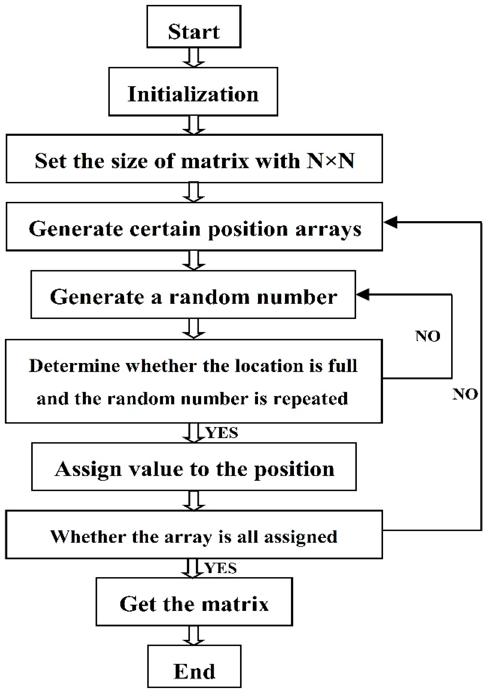
A matrix-type random coding way is proposed to design 2-bit coding MS, and the coding flowchart is shown in Figure 1. The basic units of “0” and “1” are placed in the matrix with a fixed ratio. In the case of “0” and “1” with same number, the co-polarization reflection phase difference is 0° and the cross-polarization reflection phase difference is 180°. Therefore, the cross-polarization component of the scattered field can be effectively canceled; leading to a better RCS reduction effect than the traditional random coding MS (the probability of “0” or “1” is 50% in each matrix unit). If the number of units “0” and “1” is not consistent, the cross-polarization component of the scattered field cannot be effectively canceled, leading to a suppression of RCS reduction. A simulation is presented to verify this assumption.
Matrix-type random coding mode Mrandom for Matlab calculation can be expressed as the following functional form:
where rand(2i) and ones(2N−i) represent the numbers of block matrix 2i × 2i, each block matrix composed of 2 N−i × 2 N−i is the same random number. The “kron” is matrix multiplication, where the Kronecker product A, B represents the larger matrix formed by the product of all the elements of matrix A and B. The open interval range of random number is (0, 1). The step to obtain the random coding pattern of the MS is as follows: Firstly, the number of different random matrices in the range of (1, N) is counted. Secondly, the number of patterns is calculated. Finally, the random numbers (0 and 1) are added to the discrete binary codes “0” and “1”, and a random coding matrix is obtained through the operation flow chart. Based on the results of simulation and optimization, we choose i = 6 and N − i = 5 to satisfy the preparation and measurement of sample. Therefore, the designed MS consists of a 6 × 6 supercell, with each supercell consisting of 5 × 5 basic units.
The general RCS expression of the scattering surface can be expressed by [46]:
where Si and Ss are the energy density of incidence and scattering, respectively; and are the amplitudes of incident and scattered electric fields, respectively; and and are the amplitudes of the incident and scattered magnetic fields, respectively. The general RCS can also be expressed in the form of dBsm:
In practical military applications, the incident wave can be equivalent to the plane wave because of the transmitting and receiving sources are far from the target. Thus, σ and r are independent of one another. The RCS reduction compared to perfect electric conductor is represented by:
For a matrix-type random coding MS, each kind of basic unit occupy the half area of total surface in the case of “0” and “1” with same number. The total reflection coefficient can be approximated as the average reflection coefficient of both elements. The RCS reduction can be approximately expressed as [46]:
where A0 and A1 are the reflection coefficient amplitudes of basic units “0” and “1”, respectively. and are the reflection phases of two basic units. The ratio of “0” and “1” basic units is introduced, which is defined as α = m0/m1, where m0 and m1 are the number of “0” and “1” units, respectively. Further, we introduce α into the formula to express the RCS reduction characteristic with different ratio. However, it can only be used as a qualitative comparison, not a quantitative representation of RCS value. The RCS reduction of 1-bit coding MS under normal incidence can be approximated as:
As shown in Equation (7), once basic units of “0” and “1” are selected, the reflection coefficient magnitude and phase can be determined. Therefore, if the ratio α is defined as a constant, the RCS reduction of MS will be fixed. In other words, for fixed α, the magnitudes of RCS reduction with different coding sequences are basically consistent under normal incidence. The ratio, scattered magnitude and phase play important roles in RCS reduction. This assumption is verified by furthering simulation and experiment.
2.2. Matrix-Type Random Coding Metasurface Arrangement
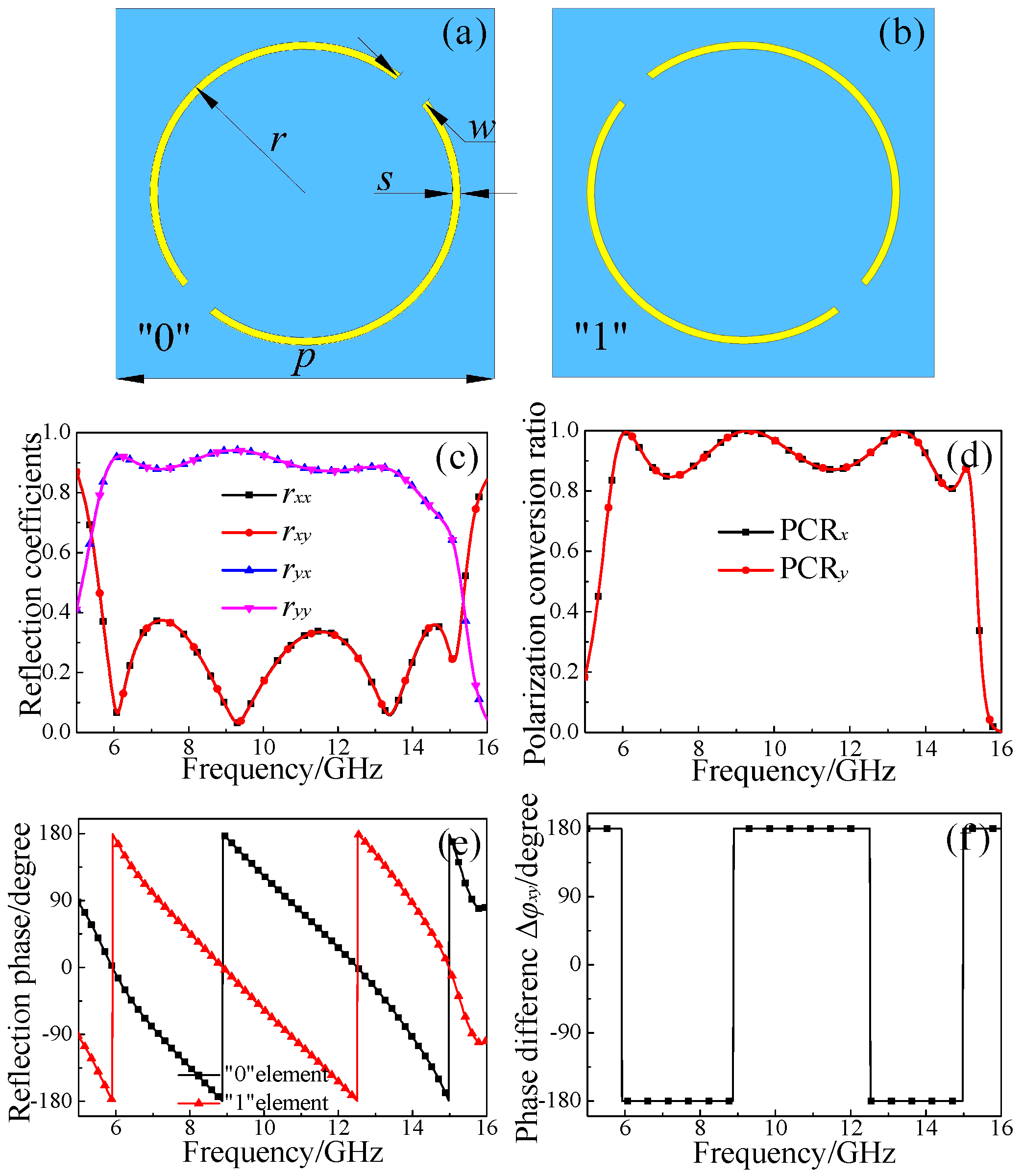
As shown in Figure 2a, the basic unit based on SRR structure is designed, which is set as “0” unit. The SRR structure is rotated counterclockwise by 90° along the wave propagation direction (shown in Figure 2b), which is set as “1” unit. The whole basic unit is divided into three functional layers, where the period is p = 10 mm. The upper layer is copper film with SRR structure, which possesses a symmetric axis along 45° with respect to x or y direction. The length of outer radius is r = 4.1 mm, the ring width is s = 0.2 mm, and the split width of ring structure is w = 1 mm. The thickness of the FR4 substrate is 3.5 mm, with the dielectric constant of 4.3 and the loss tangent angle of 0.025. The back layer copper film and the upper layer copper film have the same thickness of 0.035 mm.
Figure 2c presents the co-polarization (rxx and ryy) and cross-polarization (ryx and rxy) reflection coefficients; the high efficient and broadband polarization conversion features can be achieved in a broadband frequency range. The cross-polarization reflection coefficients (ryx and rxy) are greater than 0.8, while the co-polarization reflection coefficients (rxx and ryy) are substantially less than 0.35 in the frequency range of 6–15 GHz. The polarization conversion capability is defined as follows [47]: PCRx = |ryx|2/(|ryx|2 + |rxx|2) and PCRy = |rxy|2/(|rxy|2 + |ryy|2). As shown in Figure 2d, the linear polarization conversion ratio of the x- and y-polarized waves is as high as 85% and reached 99% at resonance frequencies.
Figure 2e,f shows the cross-polarization phase and phase difference of “0” and “1” basic units, respectively. It can be observed that the phase of the “0” and “1” basic unit is different, although the magnitude of the reflection coefficients of co- and cross-polarization is the same. In addition, the phase gradient of designed MS is 180° in the frequency range of 5–16 GHz. Therefore, we use the characteristic of cross-polarization phase difference ±180° to design the matrix-type random coding MS, which can be applied to achieve the broadband RCS reduction.
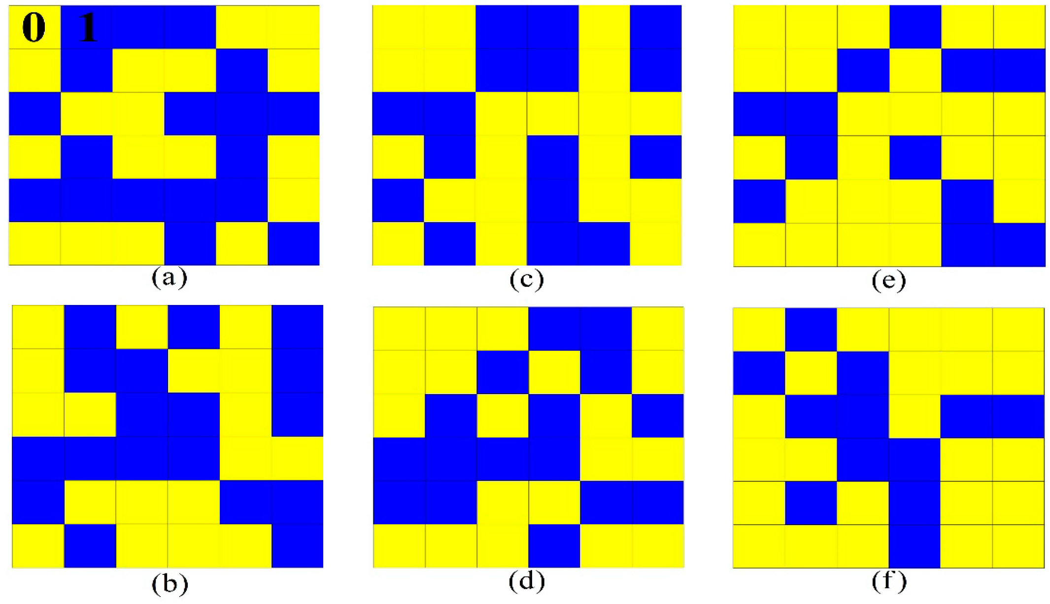
To verify the proposed hypothesis and explore the RCS reduction characteristic of matrix-type random coding MSs, six kinds of arrangements with different ratio of “0” and “1” are designed, in which m0 and m1 are the number of “0” and “1” basic units. As for the two basic units, the reflection coefficients and polarization conversion rates are consistent, the units “0” and “1” can be interchanged, and the meaning of the expression is the same. Figure 3a,b presents the schematics of coding a and b with the ratio α = m0/m1 = 1/1. Figure 3c,d presents the schematics of coding c and d with the ratio α = m0/m1 = 5/4. Meanwhile, the coding e and f with the ratio α = m0/m1 = 2/1 are shown in Figure 3e,f. By applying the matrix-type random coding, the direction of energy scattering can be changed to form a diffuse reflection for the incident EM waves; it is possible to achieve the high efficient RCS reduction characteristic under normal incidence.
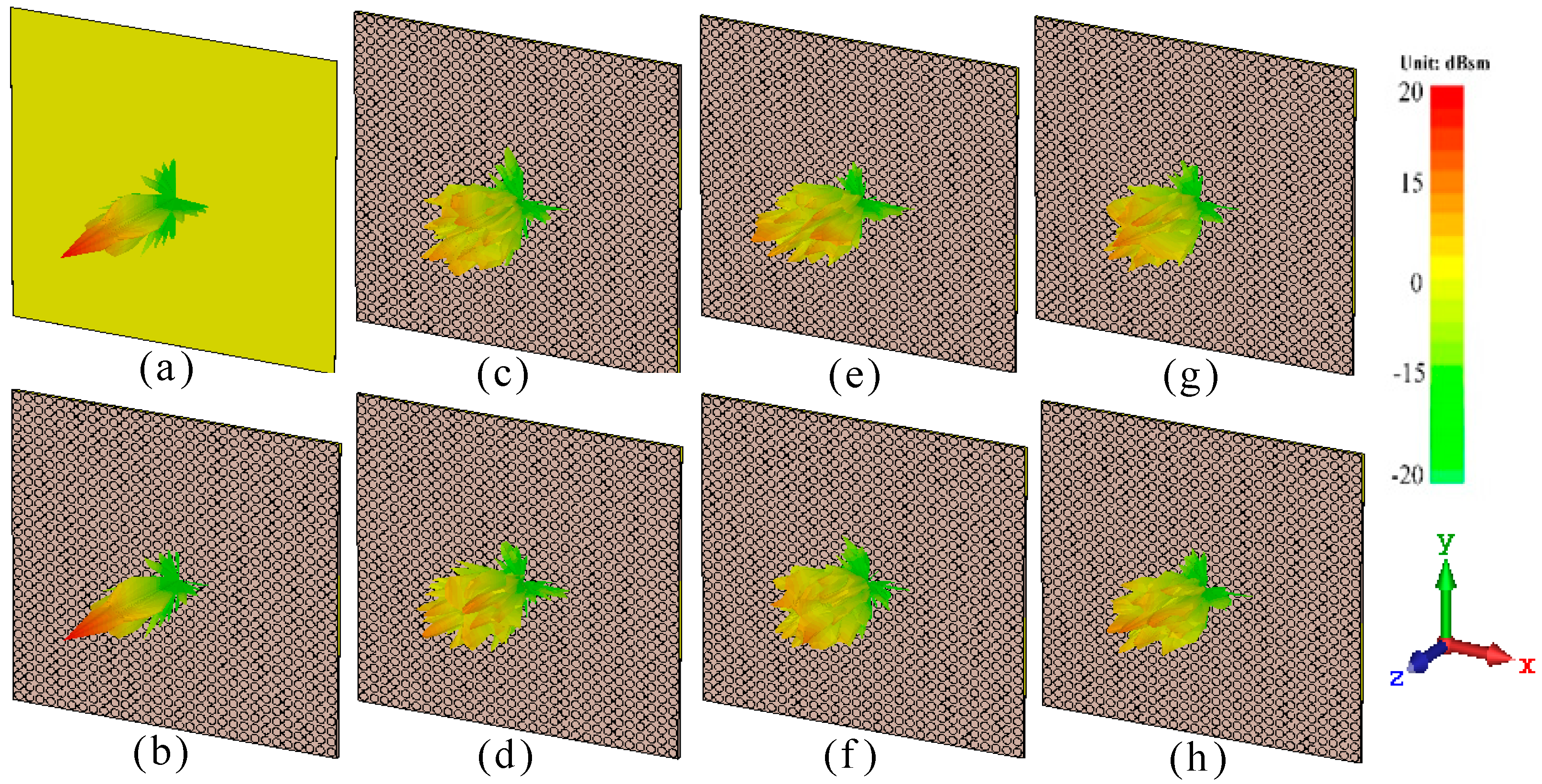
To meet the periodic boundary conditions required of simulation, the 5 × 5 basic units are set as a supercell, and a series of coding arrangements are designed to explore the RCS reduction characteristic of MS. Figure 4a–h presents the far-field scattering characteristic diagram of different coding MSs at 9.5 GHz with the area of 300 × 300 mm2. Figure 4a presents the scattering characteristic of metal plate with a strong normal scattering capability, which can be used as a reference. Figure 4b shows the upright energy scattering direction of coding 0 or 1, which is the same as the energy scattering of metal plate. Figure 4c–h shows the scattering characteristic of coding a to f, the incident EM wave energy scattering is diverged to all around, and the scattering capability is relatively weak at single direction. Thus, these results indicate that the matrix-type random coding MSs have good scattering performance.
3. Simulation and Experiment
3.1. Simulation and Analysis of Matrix-Type Coding Metasurfaces
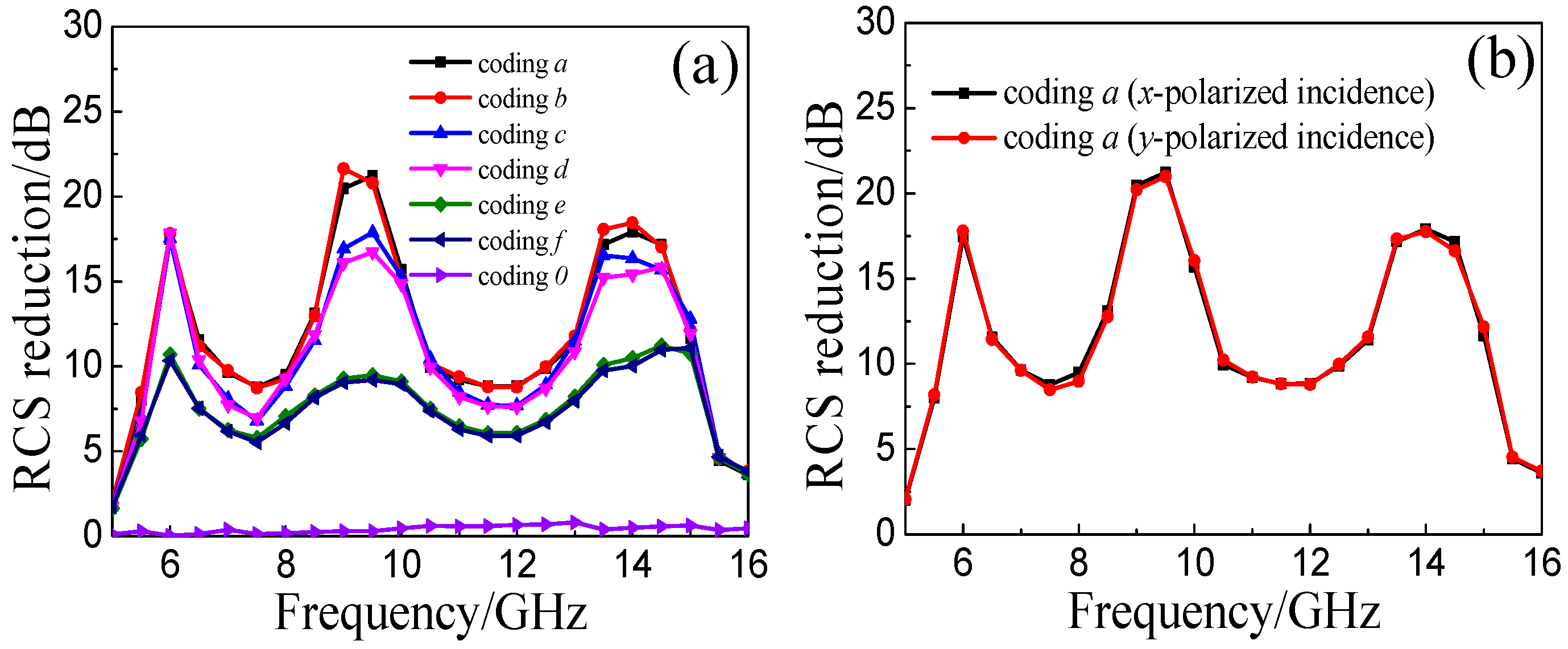
The frequency domain solver in EM simulation software of CST MICROWAVE STUDIO is used to perform the numerical simulation. As shown in Figure 5a, the numerical results of coding a to f are depicted to explore the RCS reduction characteristics of different ratio combinations. The coding 0 presents the RCS reduction of coding 0 or 1, the numerical value is essentially zero in the frequency range of 5–16 GHz, which means the single coding MS cannot reduce the RCS. The coding a and b are the MSs with the ratio α = m0/m1 = 1/1; the coding c and d present the ratio α = m0/m1 = 5/4; and the coding e and f present the ratio α = m0/m1 = 2/1. It can be seen clearly that the RCS reduction curves of different coding sequences with fixed ratio α are basically consistent. The RCS reduction will increase with decrease of the numerical value of α in the whole interested frequency range. The optimal RCS reduction result is presented at α = m0/m1 = 1/1; these results verify the above theoretical assumptions.
As shown in Figure 5b, the RCS reduction curves of coding a are basically consistent at x- and y-polarized wave incidence, which indicates a polarization-insensitive property of the proposed MSs. In addition, the RCS reduction of coding a is greater than 8 dB in the whole frequency range of 5.5–15 GHz, and the RCS reduction reaches a maximum of 21 dB at 9.5 GHz.
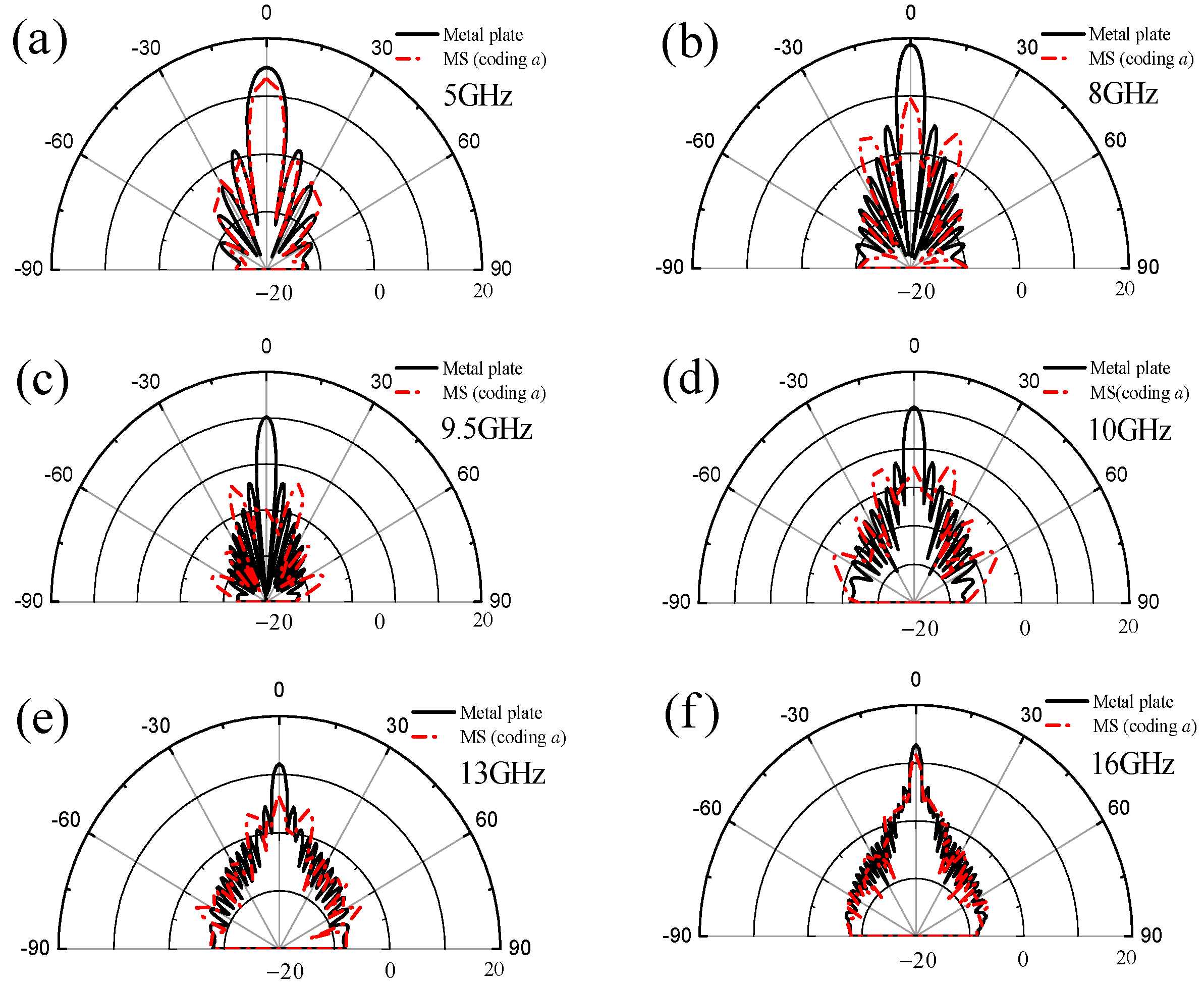
To further discuss the energy scattering characteristic of matrix-type random coding MS, the scattering patterns of coding a under normal incidence are studied, as shown in Figure 6a–f. Here is a comparison of coding a and metal plate with the same size 300 × 300 mm2 at 5, 8, 9.5, 10, 13, and 16 GHz. According to “energy conservation law”, the main lobe energy can be suppressed by enhancing the scattering EM energy of side lobe, so an effective RCS reduction can be achieved under normal incidence. The metal plate has a strong main lobe in whole interested frequency range. As shown in Figure 6a,f, the MS has almost no inhibitory effect on main lobe at 5 and 16 GHz. Figure 6b,e shows that the main lobe energy of MS has a certain suppression compared with the metal plate at 8 and 13 GHz. The scattering EM energy is scattered to all around, as shown in Figure 6c,d, which indicates the MS has a significant inhibitory effect on main lobe at 9.5 GHz and 10 GHz, respectively. Generally, the closer it is to the center frequency of the basic unit, the better the effect of reducing RCS can be achieved. Thus, the matrix-type random coding MS allows a wideband and high efficient RCS reduction by adjusting the scattered field simply compared with works proposed before [15,16].
3.2. Measurement and Analysis of Matrix-Type Coding Metasurface
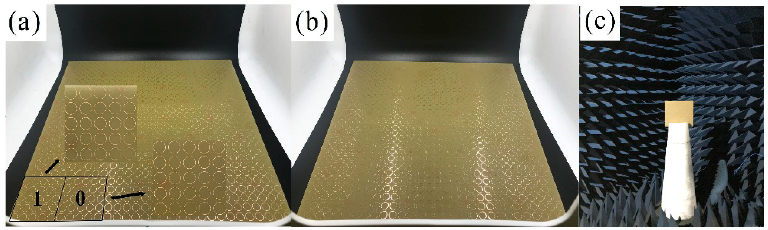
To further verify the theoretical assumptions and numerical simulation, as shown in Figure 7a,b, two MS samples of coding a and b were fabricated and measured. The area of MS is 300 × 300 mm2, and the thickness of overall design is 3.57 mm. Each sample consists of 6 × 6 supercells and each supercell consists of 5 × 5 basic units of “0” or “1”. As shown in Figure 7c, the two samples were measured in the EM anechoic chamber, the transmitting and receiving horns were fixed on the same height level in front of the foam tower. The horn antenna connected to Agilent Technologies N5244A Vector Analyzer was used to measure the RCS of samples. Firstly, the empty darkroom was calibrated before measuring the MS sample. Secondly, the metal ball was placed on the foam tower for calibration as a reference. Thirdly, the MS sample and metal plate were placed on the foam tower for testing to get the RCS value. In measurement, the area of the MS sample was the same as the metal plate. Finally, the RCS reduction of MS sample plate could be obtained by comparing the RCS value of the MS with the metal plate.
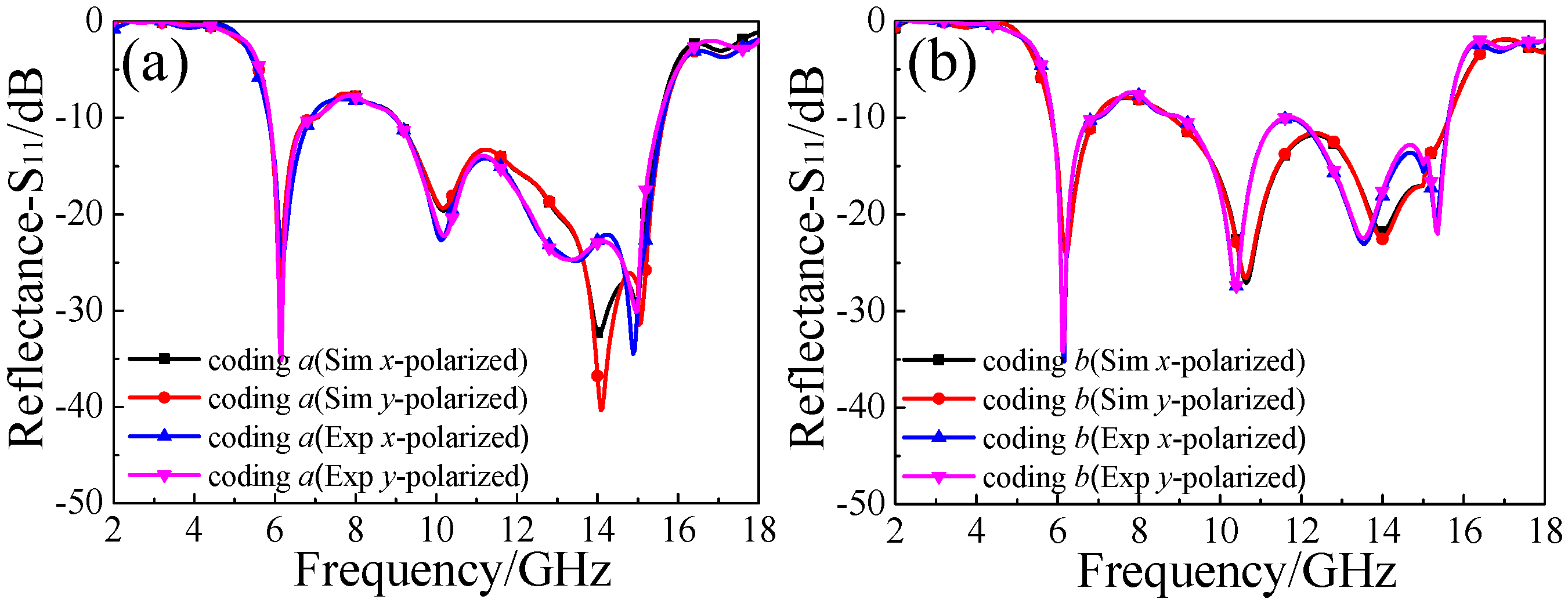
The reflectance of simulation and experiment at x- and y-polarized wave incidence are shown in Figure 8a,b. The simulated results are slightly different from the measured ones, which is mainly due to the error occurring in preparation, such as the flatness and the thickness of samples. On the whole, the simulated and measured curves of coding a and b are consistent well in the entire frequency range of 2–18 GHz, which reveals the polarization-insensitivity of matrix-type random coding MS. The reflectance of coding a and b are less than −10 dB on average in the frequency range of 5.8–15.5 GHz under normal incidence, which presents an excellent broadband RCS reduction characteristic compared with other works [6,7,8].
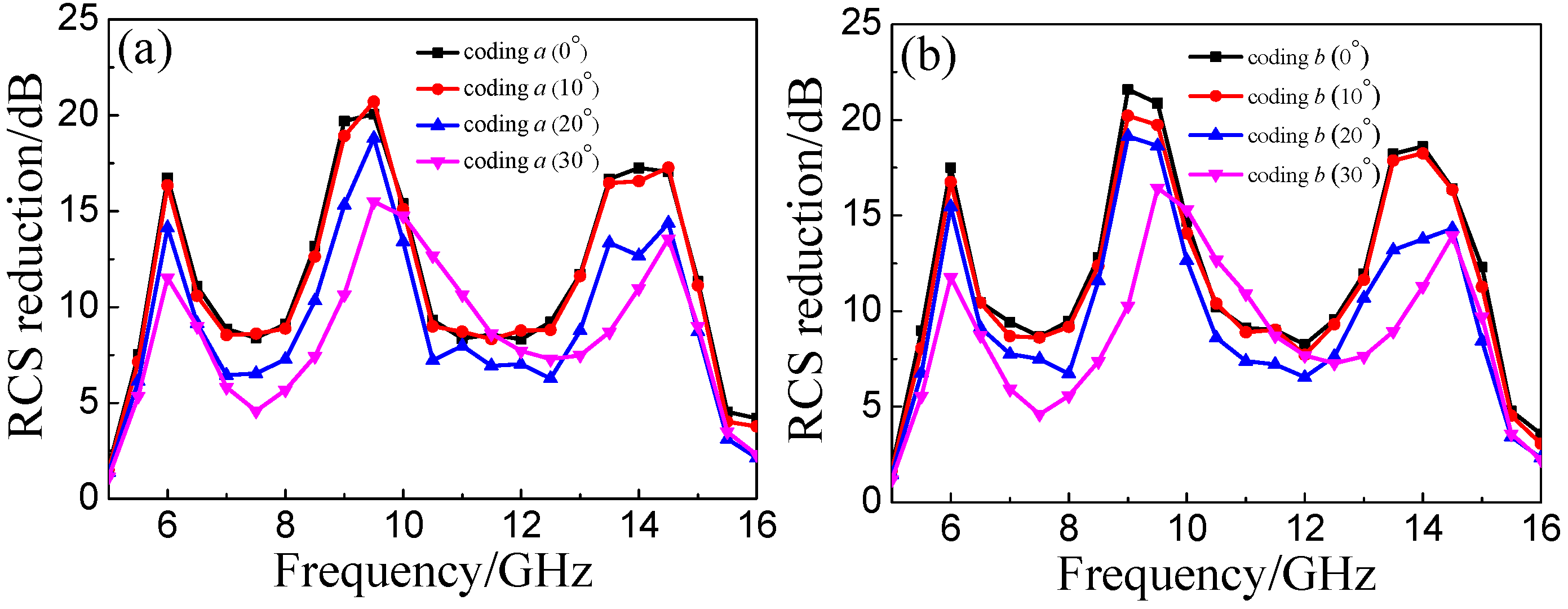
Figure 9a,b shows the RCS reduction of the MS samples under oblique incidence. The RCS reduction is greater than 10 dB in the frequency range of 5.5–15 GHz under normal incidence. For a small oblique incidence of 10°, the average magnitude of RCS reduction is basically consistent with the one of 0°. With the incident angle increasing to 20° and 30°, the RCS reduction effect is suppressed obviously. However, it still presents a more than 5 dB of RCS reduction in a broadband frequency range. A comparison of performance (Table 1) shows that our design has a superior performance in bandwidth and magnitude of RCS reductions compared with the previous reported works [22,33,41,42]. In other words, a considerable RCS reduction of matrix-type random coding MS can be achieved in oblique incident case, which further verifies the excellent RCS reduction characteristic within a wide range of incident angles compared with previous works [17,18].
4. Conclusions
In this study, a series of matrix-type random coding MSs is designed to explore the RCS reduction characteristic. The coding method of MS with different ratio of “0” and “1” units is proposed, and then, the RCS reduction mechanism of different arrangements is discussed theoretically. To analyze the energy scattering characteristic of random coding sequences, the designed MSs were simulated to get the RCS reduction curves and the scattering patterns under normal incidence. For MS samples of coding a and b, the reflectance was less than −10 dB on average under x- and y-polarized wave incidence in the frequency range of 5.8–15.5 GHz, the average RCS reduction is basically larger than 10 dB under normal incidence in the frequency range of 5.5–15 GHz. The matrix–type coding MS presents a broadband RCS reduction characteristic. At oblique incidence, an effective RCS reduction characteristic can also be achieved. Compared with previous works [21,22,23,24,33,34,35,36,37,38,39,40,41,42], our design of the matrix-type random coding MSs has better broadband RCS reduction and wide-angle incidence tolerance. The designed MS is expected to have potential applications in the field of stealth.
Author Contributions
J.J.Y. and Y.Z.C. designed and performed the experiments; D.Q. and R.Z.G. analyzed the data and contributed reagents/materials/analysis tools; J.J.Y. wrote the paper; and Y.Z.C. and R.Z.G. revised the paper.
Funding
This work was supported by the National Natural Science Foundation of China (U1435209, and 61605147), and the Natural Science Foundation of Hubei China (Grant No. 2017CFB588).
Conflicts of Interest
The authors declare no conflict of interest.
References
- Pendry, J.B.; Schurig, D.; Smith, D.R. Controlling electromagnetic fields. Science 2006, 312, 1780–1782. [Google Scholar] [CrossRef] [PubMed]
- Martin, F.; Falcone, F.; Bonache, J.; Marques, R. Miniaturized coplanar waveguide stop band filters based on multiple tuned split ring resonators. IEEE Microw. Wirel. Compos. Lett. 2003, 13, 511–513. [Google Scholar] [CrossRef]
- Cui, T.J.; Qi, M.Q.; Wan, X.; Zhao, J.; Cheng, Q. Coding metamaterials, digital metamaterials and programmable metamaterials. Light Sci. Appl. 2014, 3, 218. [Google Scholar] [CrossRef]
- Smith, D.R.; Pendry, J.B.; Wiltshire, M.C.K. Metamaterials and negative refractive index. Science 2004, 305, 788–792. [Google Scholar] [CrossRef] [PubMed]
- Iovine, R.; La Spada, L.; Vegni, L. Modified bow-tie nanoparticles operating in the visible and near infrared frequency regime. Adv. Nanopart. 2013, 2, 21. [Google Scholar] [CrossRef]
- Iovine, R.; La Spada, L.; Vegni, L. Nanoparticle device for biomedical and optoelectronics applications. COMPEL Int. J. Comput. Math. Electr. Electron. 2013, 32, 1596–1608. [Google Scholar] [CrossRef]
- La Spada, L.; Iovine, R.; Tarparelli, R.; Vegni, L. Conical nanoparticles for blood disease detection. Adv. Nanopart. 2013, 2, 259. [Google Scholar] [CrossRef]
- Iovine, R.; La Spada, L.; Vegni, L. Nanoplasmonic sensor for chemical measurements. Opt. Sens. 2013, 8774, 877411. [Google Scholar]
- La Spada, L.; Vegni, L. Near-zero-index wires. Opt. Express 2017, 25, 23699–23708. [Google Scholar] [CrossRef] [PubMed]
- Novoselov, K.S.; Fal’ko, V.I.; Colombo, L.; Gellert, P.R.; Schwab, M.G.; Kim, K. A roadmap for graphene. Nature 2012, 490, 192. [Google Scholar] [CrossRef] [PubMed]
- Wang, P.; Zhang, Y.; Chen, H.; Zhou, Y.; Jin, F.; Fan, H. Broadband radar absorption and mechanical behaviors of bendable over-expanded honeycomb panels. Compos. Sci. Technol. 2018, 162, 33–48. [Google Scholar] [CrossRef]
- Mittal, G.; Pathak, N.P. Design, analysis and characterisation of spoof surface plasmon polaritons based wideband bandpass filter at microwave frequency. Def. Sci. J. 2018, 68, 300–306. [Google Scholar] [CrossRef]
- Zheludev, N.I.; Kivshar, Y.S. From metamaterials to metadevices. Nat. Mater. 2012, 11, 917. [Google Scholar] [CrossRef] [PubMed]
- Kildishev, A.V.; Boltasseva, A.; Shalaev, V.M. Planar photonics with metasurfaces. Science 2013, 339, 1232009. [Google Scholar] [CrossRef] [PubMed]
- Qin, F.; Ding, L.; Zhang, L.; Monticone, F.; Chum, C.C.; Deng, J.; Mei, S.; Li, Y.; Teng, Y.; Hong, M.; et al. Hybrid bilayer plasmonic metasurface efficiently manipulates visible light. Sci. Adv. 2016, 2, E1501168. [Google Scholar] [CrossRef] [PubMed]
- La Spada, L.; Haq, S.; Hao, Y. Modeling and design for electromagnetic surface wave devices. Radio Sci. 2017, 52, 1049–1057. [Google Scholar] [CrossRef] [Green Version]
- Cai, W.; Chettiar, U.K.; Kildishev, A.V.; Shalaev, V.M. Optical cloaking with metamaterials. Nat. Photonics 2007, 1, 224. [Google Scholar] [CrossRef] [Green Version]
- Liu, Y.; Hao, Y.; Li, K.; Gong, S. Radar cross section reduction of a microstrip antenna based on polarization conversion metamaterial. IEEE Antennas Wirel. Propag. Lett. 2016, 15, 80–83. [Google Scholar] [CrossRef]
- Song, Y.C.; Ding, J.; Guo, C.J.; Ren, Y.H.; Zhang, J.K. Radar cross-section reduction based on an iterative fast Fourier transform optimized metasurface. Mod. Phys. Lett. B 2016, 30, 1650233. [Google Scholar] [CrossRef]
- Selvaraju, R.; Jamaluddin, M.H.; Kamarudin, M.R.; Nasir, J.; Hashim, D. Complementary split ring resonator for isolation enhancement in 5G communication antenna array. Prog. Electromagn. Res. 2018, 83, 217–228. [Google Scholar] [CrossRef]
- Su, P.; Zhao, Y.J.; Jia, S.L.; Shi, W.W.; Wang, H.L. An ultra-wideband and polarization-independent metasurface for RCS reduction. Sci. Rep. 2016, 6, 20387. [Google Scholar] [CrossRef] [PubMed]
- Sun, H.Y.; Gu, C.Q.; Chen, X.L.; Li, Z.; Liu, L.L.; Xu, B.Z.; Zhou, Z.C. Broadband and broad-angle polarization-independent metasurface for radar cross section reduction. Sci. Rep. 2017, 7, 40782. [Google Scholar] [CrossRef] [PubMed]
- Chen, K.; Cui, L.; Feng, Y.J.; Zhao, J.M.; Jiang, T.; Zhu, B. Coding metasurface for broadband microwave scattering reduction with optical transparency. Opt. Express 2017, 25, 5571–5579. [Google Scholar] [CrossRef] [PubMed]
- Cheng, Y.Z.; Wu, C.J.; Ge, C.C.; Yang, J.J.; Pei, X.J.; Jia, F.; Gong, R.Z. An ultra-thin dual-band phase-gradient metasurface using hybrid resonant structures for backward RCS reduction. Appl. Phys. B 2017, 123, 143. [Google Scholar] [CrossRef]
- Shelby, R.A.; Smith, D.R.; Schultz, S. Experimental verification of a negative index of refraction. Science 2001, 292, 77–79. [Google Scholar] [CrossRef] [PubMed]
- Li, Y.; Zhang, J.; Qu, S. Wideband radar cross section reduction using two-dimensional phase gradient metasurfaces. Appl. Phys. Lett. 2014, 104, 221110. [Google Scholar] [CrossRef]
- Sui, S.; Ma, H.; Wang, J.; Pang, Y.; Feng, M.; Xu, Z.; Qu, S. Absorptive coding metasurface for further radar cross section reduction. J. Appl. Phys. 2018, 51, 065603. [Google Scholar] [CrossRef] [Green Version]
- Alrasheed, S.; Di Fabrizio, E. Design and simulation of reflect-array metasurfaces in the visible regime. Appl. Opt. 2017, 56, 3213–3218. [Google Scholar] [CrossRef] [PubMed]
- Mitrofanov, O.; Viti, L.; Dardanis, E. Near-field terahertz probes with room-temperature nanodetectors for subwavelength resolution imaging. Sci. Rep. 2017, 7, 44240. [Google Scholar] [CrossRef] [PubMed] [Green Version]
- Politano, A.; Viti, L.; Vitiello, M.S. Optoelectronic devices, plasmonics, and photonics with topological insulators. APL Mater. 2017, 5, 035504. [Google Scholar] [CrossRef] [Green Version]
- Kou, N.; Liu, H.; Li, L. A transplantable frequency selective metasurface for high-order harmonic suppression. Appl. Sci. 2017, 7, 1240. [Google Scholar] [CrossRef]
- Li, Y.; Zhang, J.; Qu, S. Achieving wideband polarization-independent anomalous reflection for linearly polarized waves with dispersionless phase gradient metasurfaces. J. Phys. D Appl. Phys. 2014, 47, 425103–425109. [Google Scholar] [CrossRef]
- Wu, C.J.; Cheng, Y.Z.; Wang, W.Y.; He, B.; Gong, R.Z. Design and radar cross section reduction experimental verification of phase gradient meta-surface based on cruciform structure. Acta Phys. Sin. 2015, 64, 064102. [Google Scholar]
- Li, Y.F.; Wang, J.; Zhang, J.; Qu, S.B.; Pang, Y.Q.; Zheng, L.; Yan, M.B.; Xu, Z.; Zhang, A.X. Ultra-wide-band Microwave composite absorbers based on phase gradient metasurfaces. Prog. Electromagn. Res. 2014, 40, 9–18. [Google Scholar] [CrossRef]
- Cheng, Y.Z.; Cheng, Z.Z.; Mao, X.S.; Gong, R.Z. Ultra-thin multi-band polarization-insensitive microwave metamaterial absorber based on multiple-order responses using a single resonator structure. Materials 2017, 10, 1241. [Google Scholar] [CrossRef] [PubMed]
- Yu, N.F.; Genevet, P.; Kats, M.A.; Aieta, F. Light propagation with phase discontinuities: Generalized laws of reflection and refraction. Science 2011, 334, 333–337. [Google Scholar] [CrossRef] [PubMed]
- Deng, G.S.; Xia, T.Y.; Fang, Y.; Yang, J.; Yin, Z.P. A polarization-dependent frequency-selective metamaterial absorber with multiple absorption peaks. Appl. Sci. 2017, 7, 580. [Google Scholar] [CrossRef]
- Huang, C.; Pan, W.B.; Ma, X.L.; Luo, X.G. Wideband radar cross-section reduction of a stacked patch array antenna using metasurface. IEEE Antennas Wirel. Propag. Lett. 2015, 14, 1369–1372. [Google Scholar] [CrossRef]
- Tian, S.; Liu, H.; Li, L. Design of 1-bit digital reconfigurable reflective metasurface for beam-scanning. Appl. Sci. 2017, 7, 882. [Google Scholar] [CrossRef]
- Yang, J.J.; Cheng, Y.Z.; Ge, C.C.; Gong, R.Z. Broadband polarization conversion metasurface based on metal cut-wire structure for radar cross section reduction. Materials 2018, 11, 626. [Google Scholar] [CrossRef] [PubMed]
- Liu, Y.; Li, K.; Jia, Y.; Hao, J.; Gong, S.; Guo, Y.J. Wideband RCS reduction of a slot array antenna using polarization conversion metasurfaces. IEEE Trans. Antennas Propag. 2016, 64, 326–331. [Google Scholar] [CrossRef]
- Zheng, Q.; Li, Y.; Zhang, J.; Ma, H.; Wang, J.; Pang, Y.; Han, Y.; Sui, S.; Shen, Y.; Chen, H.; et al. Wideband, wide-angle coding phase gradient metasurfaces based on Pancharatnam-Berry phase. Sci. Rep. 2017, 7, 43543. [Google Scholar] [CrossRef] [Green Version]
- Iovine, R.; La Spada, L.; Tarparelli, R.; Vegni, L. Spectral green’s function for SPR meta-structures. Mater. Sci. Forum 2014, 792, 110–114. [Google Scholar] [CrossRef]
- Padooru, Y.R.; Yakovlev, A.B.; Kaipa, C.S.R.; Hanson, G.W.; Medina, F.; Mesa, F.; Glisson, A.W. New absorbing boundary conditions and analytical model for multilayered mushroom-type metamaterials: Applications to wideband absorbers. IEEE Trans. Antennas Propag. 2012, 60, 5727–5742. [Google Scholar] [CrossRef]
- La Spada, L.; Vegni, L. Electromagnetic nanoparticles for sensing and medical diagnostic applications. Materials 2018, 11, 603. [Google Scholar] [CrossRef] [PubMed]
- Balanis, C.A. Antenna Theory: Analysis and Design, 3rd ed.; Wiley: New York, NY, USA, 2005. [Google Scholar]
- Zhao, J.C.; Cheng, Y.Z.; Cheng, Z.Z. Design of a photo-excited switchable broadband reflective linear polarization conversion metasurface for terahertz waves. IEEE Photonics J. 2018, 10, 1–10. [Google Scholar] [CrossRef]
Figure 1.
Matrix-type random coding flowchart.

Figure 2.
(a) Basic unit “0”; (b) basic unit “1”; (c) the reflection coefficients of “0” and “1”; (d) the linear polarization conversion ratio for the normal incident x- and y-polarized wave; (e) the cross-polarization phase of “0” and “1”; and (f) the cross-polarization phase difference of “0” and “1”.

Figure 3.
Arrangements of six matrix-type random coding MS: (a,b) coding a and b with the ratio α = m0/m1 = 1/1; (c,d) coding c and d with the ratio α = m0/m1 = 5/4; and (e,f) coding e and f with the ratio α = m0/m1 = 2/1.
Figure 3.
Arrangements of six matrix-type random coding MS: (a,b) coding a and b with the ratio α = m0/m1 = 1/1; (c,d) coding c and d with the ratio α = m0/m1 = 5/4; and (e,f) coding e and f with the ratio α = m0/m1 = 2/1.

Figure 4.
Far-field scattering results of: (a) metal plate; (b) coding 0 or 1, and matrix-type random coding MS; (c) coding a; (d) coding b; (e) coding c; (f) coding d; (g) coding e; and (h) coding f at 9.5 GHz.
Figure 4.
Far-field scattering results of: (a) metal plate; (b) coding 0 or 1, and matrix-type random coding MS; (c) coding a; (d) coding b; (e) coding c; (f) coding d; (g) coding e; and (h) coding f at 9.5 GHz.

Figure 5.
(a) RCS reduction of matrix-type random coding MS with different ratio combinations of “0” and “1” units; and (b) RCS reduction of coding a at x- and y-polarized wave incidence.
Figure 5.
(a) RCS reduction of matrix-type random coding MS with different ratio combinations of “0” and “1” units; and (b) RCS reduction of coding a at x- and y-polarized wave incidence.

Figure 6.
2D scattering patterns of the coding a and metal plate in the xoz-plane at: (a) 5 GHz; (b) 8 GHz; (c) 9.5 GHz; (d) 10 GHz; (e) 13 GHz; and (f) 16 GHz.
Figure 6.
2D scattering patterns of the coding a and metal plate in the xoz-plane at: (a) 5 GHz; (b) 8 GHz; (c) 9.5 GHz; (d) 10 GHz; (e) 13 GHz; and (f) 16 GHz.

Figure 7.
The matrix-type random coding MS templates: (a) coding a; (b) coding b; and (c) the measurement setup at microwave anechoic chamber.
Figure 7.
The matrix-type random coding MS templates: (a) coding a; (b) coding b; and (c) the measurement setup at microwave anechoic chamber.

Figure 8.
The simulated and measured reflectances of the MS samples at x- and y-polarized wave incidence: (a) coding a; and (b) coding b.
Figure 8.
The simulated and measured reflectances of the MS samples at x- and y-polarized wave incidence: (a) coding a; and (b) coding b.

Figure 9.
Measured RCS reduction of samples under normal incidence and oblique incidence of 10°, 20°, and 30°: (a) coding a; and (b) coding b.
Figure 9.
Measured RCS reduction of samples under normal incidence and oblique incidence of 10°, 20°, and 30°: (a) coding a; and (b) coding b.


© 2018 by the authors. Licensee MDPI, Basel, Switzerland. This article is an open access article distributed under the terms and conditions of the Creative Commons Attribution (CC BY) license (http://creativecommons.org/licenses/by/4.0/).
Share and Cite
MDPI and ACS Style
Yang, J.J.; Cheng, Y.Z.; Qi, D.; Gong, R.Z. Study of Energy Scattering Relation and RCS Reduction Characteristic of Matrix-Type Coding Metasurface. Appl. Sci. 2018, 8, 1231. https://doi.org/10.3390/app8081231
AMA Style
Yang JJ, Cheng YZ, Qi D, Gong RZ. Study of Energy Scattering Relation and RCS Reduction Characteristic of Matrix-Type Coding Metasurface. Applied Sciences. 2018; 8(8):1231. https://doi.org/10.3390/app8081231
Chicago/Turabian StyleYang, Jia Ji, Yong Zhi Cheng, Dong Qi, and Rong Zhou Gong. 2018. "Study of Energy Scattering Relation and RCS Reduction Characteristic of Matrix-Type Coding Metasurface" Applied Sciences 8, no. 8: 1231. https://doi.org/10.3390/app8081231
Note that from the first issue of 2016, this journal uses article numbers instead of page numbers. See further details here.