Research on Compression Behavior of Square Thin-Walled CFST Columns with Steel-Bar Stiffeners


Abstract
:1. Introduction
2. Experimental Program
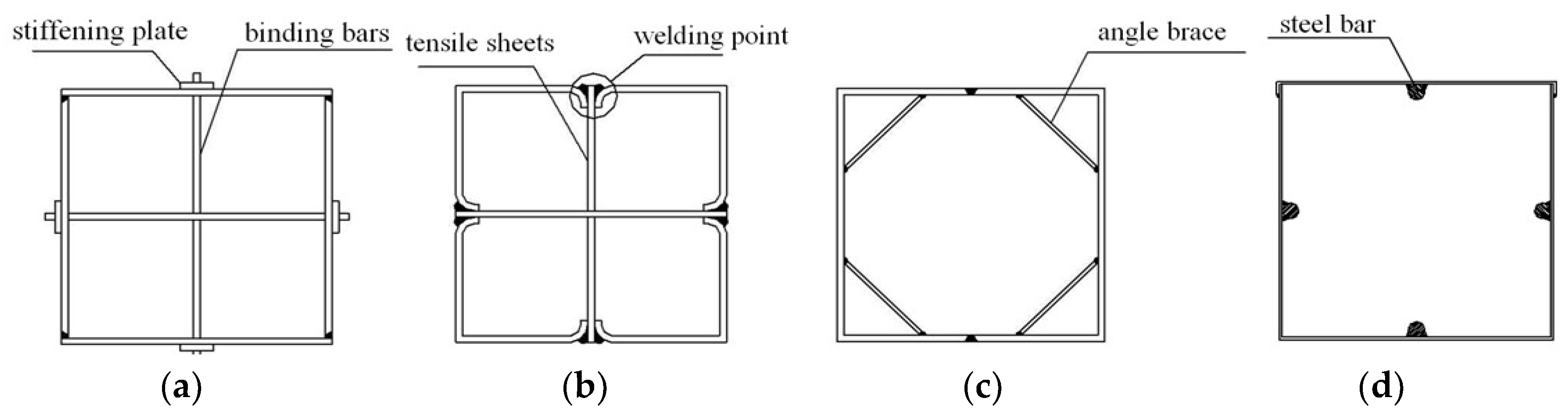
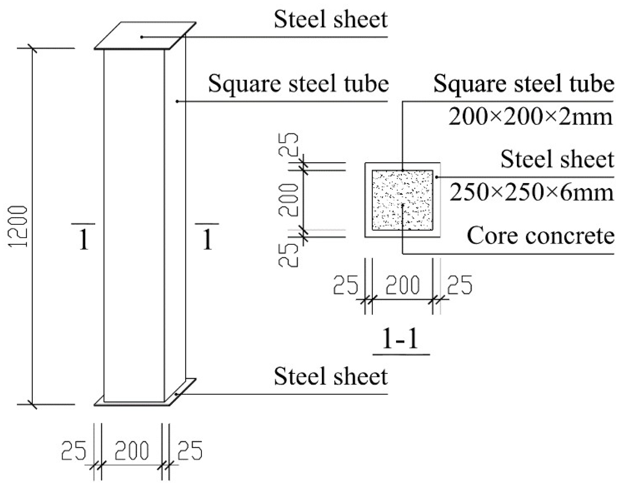
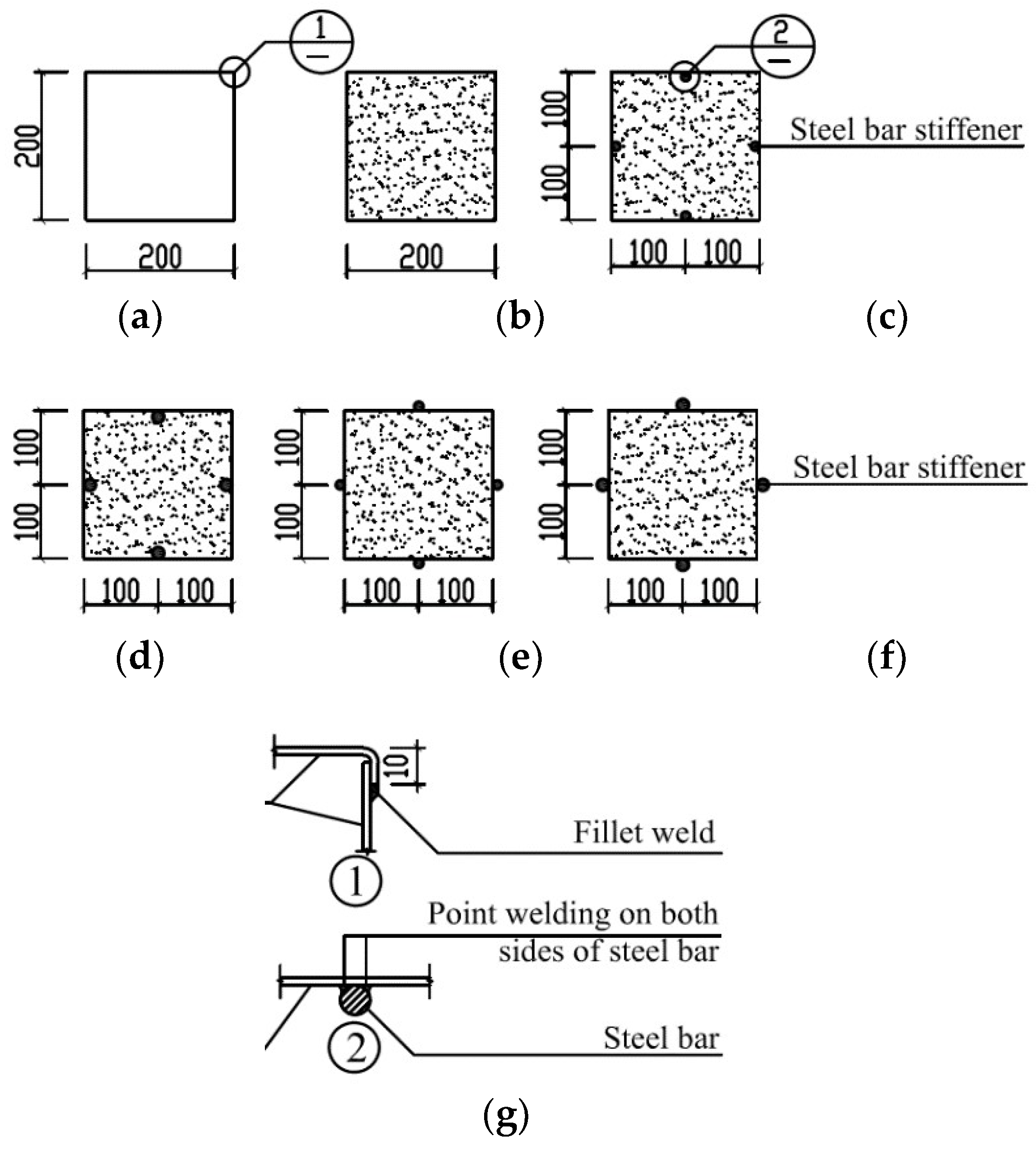
2.1. Test Specimens
2.2. Specimen Fabrication
2.3. Materials Properties
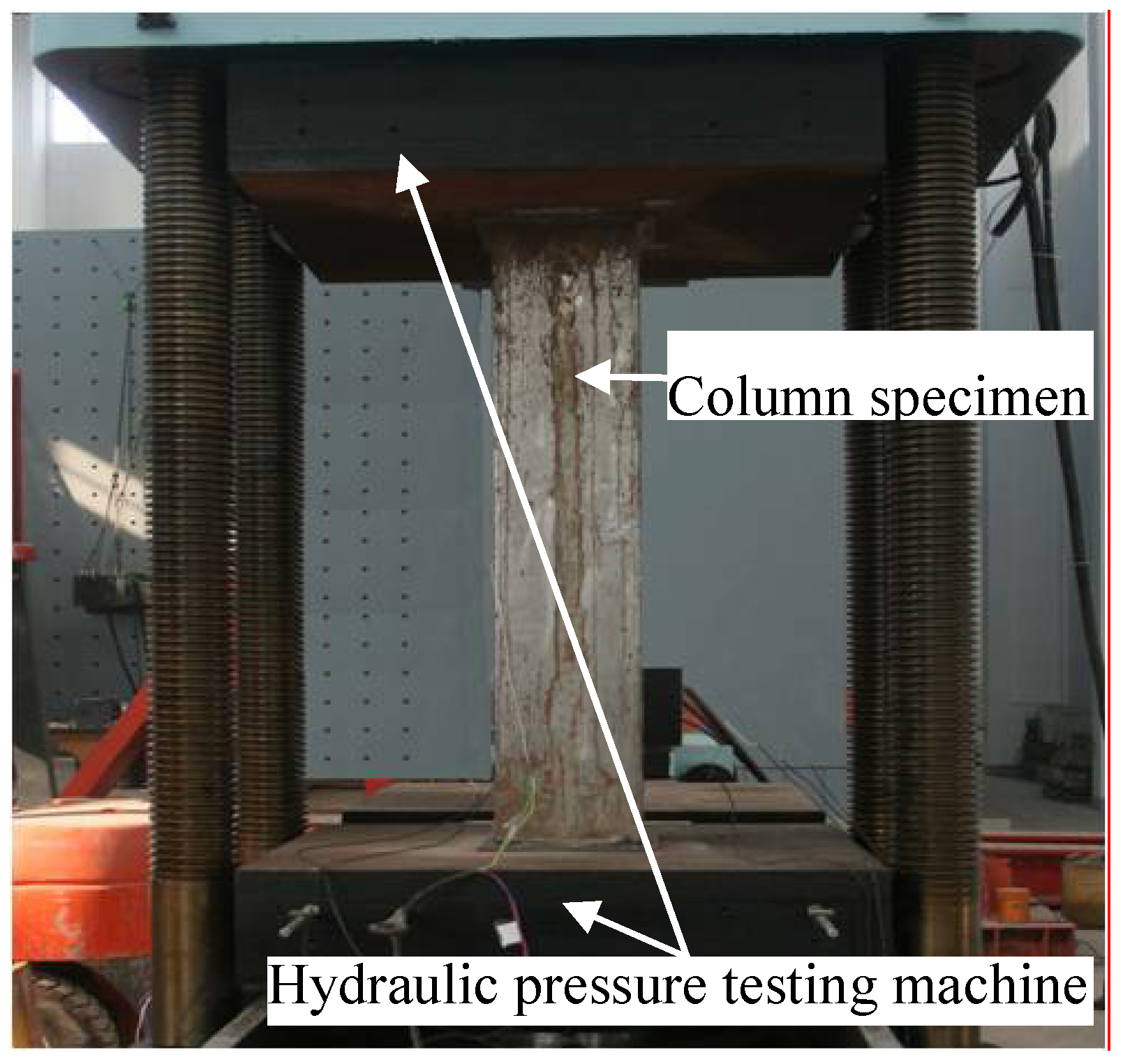
2.4. Loading and Measurement
3. Test Results
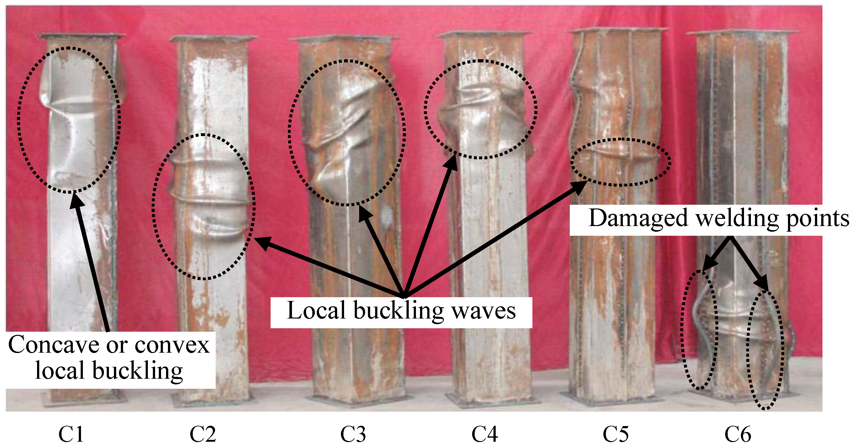
3.1. Failure Mode
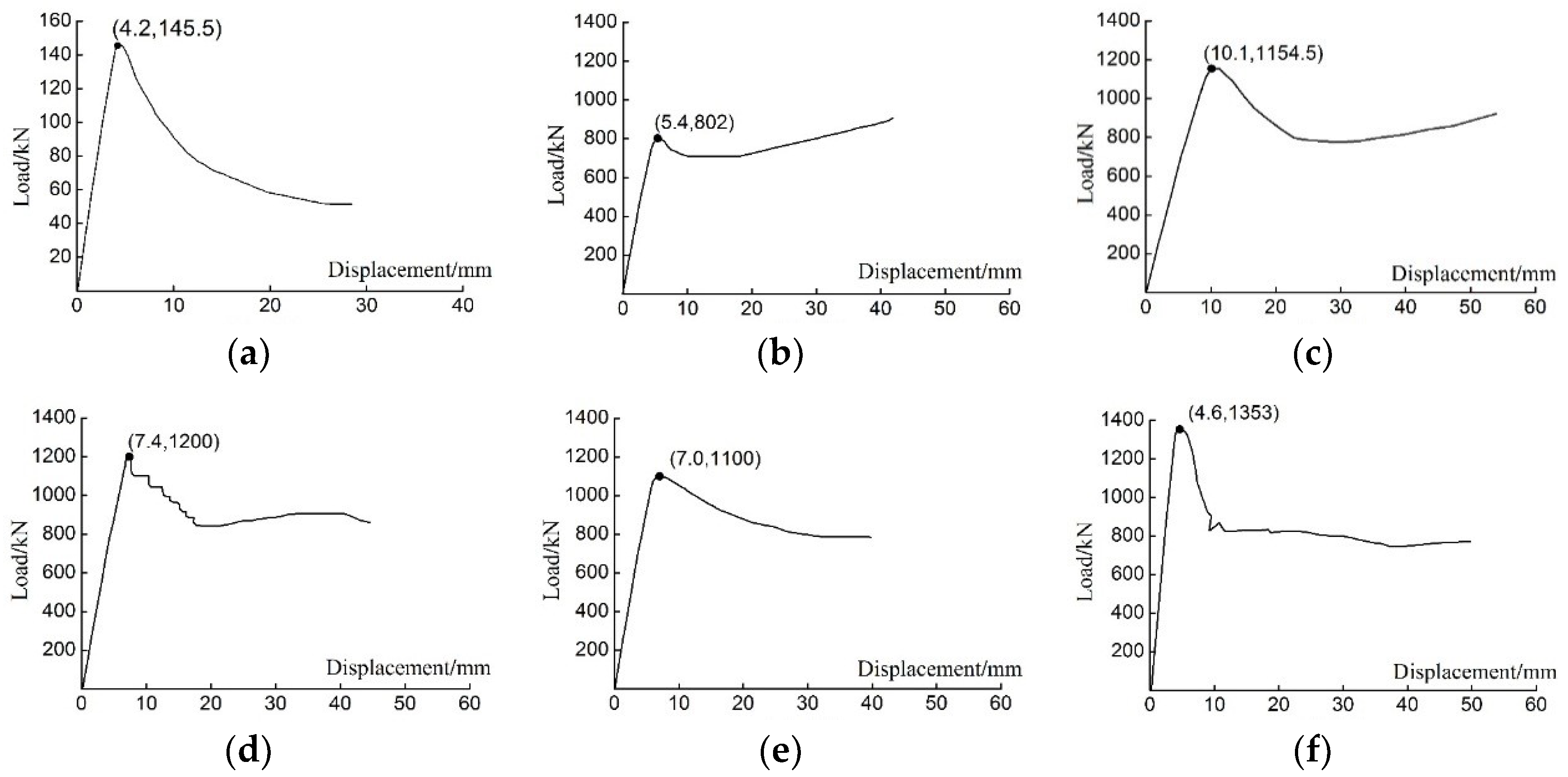
3.2. Load–Displacement Relationship
3.3. Ultimate Load
3.4. Ductility
3.5. Local Buckling
4. Summary and Conclusions
Author Contributions
Funding
Conflicts of Interest
References
- Ahmad, F. Local Buckling Restraining Behavior of Concrete-Filled Steel Tubular Columns under Seismic Loads. Master’s Thesis, University of North Dakota, Grand Forks, ND, USA, 2015. [Google Scholar]
- Montuori, R.; Piluso, V. Analysis and modelling of CFT members: Moment curvature analysis. Thin-Walled Struct. 2015, 86, 157–166. [Google Scholar] [CrossRef]
- Elchalakani, M.; Karrech, A.; Hassanein, M.F.; Yang, B. Plastic and yield slenderness limits for circular concrete filled tubes subjected to static pure bending. Thin-Walled Struct. 2016, 109, 50–64. [Google Scholar] [CrossRef]
- Choi, I.R.; Chung, K.S.; Kim, C.S. Experimental study on rectangular CFT columns with different steel grades and thicknesses. J. Constr. Steel Res. 2017, 130, 109–119. [Google Scholar] [CrossRef]
- Campiche, A.; Shakeel, S.; Macillo, V.; Terracciano, M.T.; Bucciero, B.; Pali, T.; Fiorino, L.; Landolfo, R. Seismic behaviour of sheathed CFS buildings: Shake table tests and numerical modelling. Ing. Sism. 2018, 35, 106–123. [Google Scholar]
- Ghazijahani, T.G.; Jiao, H.; Holloway, D. Timber filled CFRP jacketed circular steel tubes under axial compression. Constr. Build. Mater. 2015, 94, 791–799. [Google Scholar] [CrossRef]
- Ghazijahani, T.G.; Asce, S.M.; Jiao, H.; Holloway, D. Concrete-Filled Circular Steel Tubes with a Timber Infill under Axial Compression. J. Struct. Eng. 2017, 143, 1–29. [Google Scholar] [CrossRef]
- Ding, F.X.; Liu, J.; Liu, X.M.; Yu, Z.W.; Li, D.W. Mechanical behavior of circular and square concrete filled steel tube stub columns under local compression. J. Thin-Walled Struct. 2015, 94, 155–166. [Google Scholar] [CrossRef] [Green Version]
- Uy, B.; Bradford, M.A. Elastic local buckling of steel plates in composite steel-concrete members. Eng. Struct. 1996, 18, 193–200. [Google Scholar] [CrossRef]
- Schnabl, S.; Jelenić, G.; Planinc, I. Analytical buckling of slender circular concrete-filled steel tubular columns with compliant interfaces. J. Constr. Steel Res. 2015, 115, 252–262. [Google Scholar] [CrossRef]
- Thai, H.T.; Uy, B.; Khan, M. A modified stress-strain model accounting for the local buckling of thin-walled stub columns under axial compression. J. Constr. Steel Res. 2015, 111, 57–69. [Google Scholar] [CrossRef]
- Dundu, M. Column buckling tests of hot-rolled concrete filled square hollow sections of mild to high strength steel. J. Eng. Struct. 2016, 127, 73–85. [Google Scholar] [CrossRef]
- Long, Y.L.; Wan, J.; Cai, J. Theoretical study on local buckling of rectangular CFT columns under eccentric compression. J. Constr. Steel Res. 2016, 120, 70–80. [Google Scholar] [CrossRef]
- Song, Y.C.; Wang, R.P.; Li, J. Local and post-local buckling behavior of welded steel shapes in partially encased composite columns. J. Thin-Walled Struct. 2016, 108, 93–108. [Google Scholar] [CrossRef]
- Patel, V.I.; Liang, Q.Q.; Hadi, M.N.S. Nonlinear analysis of biaxially loaded rectangular concrete-filled stainless steel tubular slender beam-columns. Eng. Struct. 2017, 140, 120–133. [Google Scholar] [CrossRef]
- Zhang, Y.C.; Chen, Y. Experimental study and finite element analysis of square stub columns with straight ribs of concrete-filled thin-walled steel tube. J. Build. Struct. 2006, 27, 16–22. (In Chinese) [Google Scholar]
- Chen, Y.; Zhang, Y.C. Experimental study and finite element analysis of square stub columns with tensile sheets of concrete–filled thin–walled steel tube. J. Build. Struct. 2006, 27, 23–29. (In Chinese) [Google Scholar]
- Zhu, C.A.; Xu, C.X. Design and Selection of constructional measures to Restrict Local Buckling of Concrete Filled Thin-Walled Square Steel Tube Columns. J. Yangtze Univ. (Nat. Sci. Ed.) Sci. Eng. V 2008, 5, 378–380. (In Chinese) [Google Scholar]
- Li, L.Z.; Jiang, C.J.; Jia, L.J.; Lu, Z.D. Local buckling of bolted steel plates with different stiffener configuration. Eng. Struct. 2016, 119, 186–197. [Google Scholar] [CrossRef]
- Wang, Y.T.; Cai, J.; Long, Y.L.; Chen, Q.J. Bearing behavior under compression and bending of concrete-filled square steel tubular columns with confined bars. Ind. Constr. 2016, 46, 142–148. (In Chinese) [Google Scholar]
- Guo, Y.L.; Zhang, B.H.; Jiang, Z.Q.; Chen, H. Critical load and application of core-separated buckling-restrained braces. J. Constr. Steel Res. 2015, 106, 1–10. [Google Scholar] [CrossRef]
- Talebi, E.; Tahir Md, M.; Zahmatkesh, F.; Kueh, B.H.A. Comparative study on the behavior of Buckling Restrained Braced frames at fire. J. Constr. Steel Res. 2014, 102, 1–12. [Google Scholar] [CrossRef]
- GB/T 228.1-2010. Metallic Materials–Tensile Testing-Part 1: Method of Test at Room Temperature; Ministry of Housing and Urban-Rural Development of the People’s Republic of China (MOHURD): Beijing, China, 2010. (In Chinese)
- GB/T 50081-2002. Standard for Test Method of Mechanical Properties on Ordinary Concrete; Ministry of Housing and Urban-Rural Development of the People’s Republic of China (MOHURD): Beijing, China, 2002. (In Chinese)
- GB 50936-2014. Technical Code for Concrete Filled Steel Tubular Structures; Ministry of Housing and Urban-Rural Development of the People’s Republic of China (MOHURD): Beijing, China, 2014. (In Chinese)
- Han, L.H.; Zhao, X.L. Test and calculations for hollow structural steel (HSS) stub columns filled with self-consolidating concrete (SCC). J. Constr. Steel Res. 2005, 61, 1241–1269. [Google Scholar] [CrossRef]


| Column Number | Stiffener Setting | Concrete Setting | Column Height (mm) | Column Width (mm) | Tube Thickness (mm) | Steel-Bar Diameter (mm) | Cross-Section Area Ratio of Steel to Column |
|---|---|---|---|---|---|---|---|
| C1 | Empty tube | No concrete | 1200 | 200 | 2 | - | 100% |
| C2 | No stiffeners | Concrete-filled | 1200 | 200 | 2 | - | 3.96% |
| C3 | Steel-bar stiffener inside tube | Concrete-filled | 1200 | 200 | 2 | 12 mm | 5.07% |
| C4 | Steel-bar stiffener inside tube | Concrete-filled | 1200 | 200 | 2 | 16 mm | 5.91% |
| C5 | Steel-bar stiffener outside tube | Concrete-filled | 1200 | 200 | 2 | 12 mm | 5.07% |
| C6 | Steel-bar stiffener outside tube | Concrete-filled | 1200 | 200 | 2 | 16 mm | 5.91% |
| Type | Yield Strength (N·mm−2) | Ultimate Strength (N·mm−2) | Elastic Modulus (N·mm−2) |
|---|---|---|---|
| Steel tube | 243.0 | 368.5 | 1.82 × 10⁵ |
| Steel bar | 231.3 | 355.3 | 1.97 × 10⁵ |
| Type | Cube Compressive Strength (N·mm−2) | Axial Compressive Strength (N·mm−2) | Elastic Modulus (N·mm−2) |
|---|---|---|---|
| Core concrete | 24.5 | 16.4 | 2.77 × 10⁴ |
| Column Number | Ass (mm2) | Nue (kN) | N0 (kN) | Nue/N0 |
|---|---|---|---|---|
| C1 | - | 145.0 | 384.9 | 0.377 |
| C2 | - | 802.0 | 1014.9 | 0.790 |
| C3 | 452.4 | 1154.5 | 1119.6 | 1.031 |
| C4 | 804.2 | 1200.0 | 1200.9 | 0.999 |
| C5 | 452.4 | 1100.0 | 1119.6 | 0.983 |
| C6 | 804.2 | 1353.0 | 1200.9 | 1.127 |
| Column Number | Δy/mm | Δmax/mm | DI |
|---|---|---|---|
| C2 | 5.1 | 17.5 | 3.43 |
| C3 | 7.2 | 14.5 | 2.01 |
| C4 | 5.0 | 10.5 | 2.10 |
| C5 | 4.4 | 14.1 | 3.20 |
| C6 | 3.5 | 8.1 | 2.31 |
| Column Number | Nu (kN) | Nq (kN) | Nq/Nu | Nqi/Nq2 |
|---|---|---|---|---|
| C1 | 145.5 | 120.0 | 0.825 | 0.194 |
| C2 | 802.0 | 620.0 | 0.773 | 1.000 |
| C3 | 1154.5 | 700.0 | 0.606 | 1.129 |
| C4 | 1200.0 | 820.0 | 0.683 | 1.323 |
| C5 | 1100.0 | 760.0 | 0.691 | 1.226 |
| C6 | 1353.0 | 880.0 | 0.650 | 1.419 |
© 2018 by the authors. Licensee MDPI, Basel, Switzerland. This article is an open access article distributed under the terms and conditions of the Creative Commons Attribution (CC BY) license (http://creativecommons.org/licenses/by/4.0/).
Share and Cite
Yang, Z.; Xu, C. Research on Compression Behavior of Square Thin-Walled CFST Columns with Steel-Bar Stiffeners. Appl. Sci. 2018, 8, 1602. https://doi.org/10.3390/app8091602
Yang Z, Xu C. Research on Compression Behavior of Square Thin-Walled CFST Columns with Steel-Bar Stiffeners. Applied Sciences. 2018; 8(9):1602. https://doi.org/10.3390/app8091602
Chicago/Turabian StyleYang, Zhao, and Chengxiang Xu. 2018. "Research on Compression Behavior of Square Thin-Walled CFST Columns with Steel-Bar Stiffeners" Applied Sciences 8, no. 9: 1602. https://doi.org/10.3390/app8091602
APA StyleYang, Z., & Xu, C. (2018). Research on Compression Behavior of Square Thin-Walled CFST Columns with Steel-Bar Stiffeners. Applied Sciences, 8(9), 1602. https://doi.org/10.3390/app8091602