Damage Mechanisms of Polymer Impregnated Carbon Textiles Used as Anode Material for Cathodic Protection


Institute of Building Materials Research at RWTH Aachen University, 52062 Aachen, Germany
*
Author to whom correspondence should be addressed.
Appl. Sci. 2019, 9(1), 110; https://doi.org/10.3390/app9010110
Submission received: 25 November 2018
/
Revised: 23 December 2018
/
Accepted: 25 December 2018
/
Published: 29 December 2018
(This article belongs to the Special Issue Textile Reinforced Cement Composites: New Insights in Structural and Material Engineering)
Abstract
:Featured Application
Conventional cathodic corrosion protection (CP) systems usually use MMO-coated titanium as anode material. Carbon textiles as anode material provide sufficient current densities for CP as well as strength for structural reinforcement. Therefore, durability is an important issue for both the structure and the CP view. This work should show the border potentials where the impregnation and sizing of carbon textiles are destroyed under anodic polarization.
Abstract
Carbon textiles as anode material for cathodic corrosion protection (CP) have been used in several reinforced steel structures. However, experience with durability is limited. To date, various influencing factors have been discovered and systematic tests on different carbon textiles with different impregnation materials in various environmental media have been carried out and considered the degradation of the impregnation materials. In this work the boundary potentials are determined at which the impregnation and sizing is destroyed under anodic polarization and the damage mechanisms are described.
1. Introduction
Carbon textiles consist of thousands of bundled carbon fibres. Before carbon fibres are combined into bundles, their surface needs to be electrochemically activated (by anodic oxidation in an electrolytic solution). Each fibre is then coated by a mixture of various chemicals (sizing) to protect it from mechanical damage during production handling and improve its wetting performance [1,2,3]. Furthermore sizing leads to an increased chemical reactive site as well as enhanced adhesion between carbon and impregnation material [4,5]. After single carbon fibres are bundled together, the so-called carbon roving is again impregnated to improve adhesion and handling for further application. Usually, epoxy resin or styrene-butadiene rubber (SBR) based polymers are used for impregnation.
The thesis of Wetjen [6] gives an overview of the production and processing of carbon. The following statements are based on this source, unless otherwise indicated. The carbon rovings usually consist of thousands of individual combined carbon fibres, which are also called filaments and have an average thickness of 5–7 microns. Carbon fibres consist of 92% by weight of carbon. They can be produced chemically from different polymers, the most common being the production from polyacrylonitrile (PAN), since the highest strengths with high carbon yield can be achieved at comparatively low price. Graphite consists of hexagonal layers in which each carbon atom is connected to three other carbon atoms with a strong covalent bond. The individual layers are connected only by relatively weak London forces, whereby the distance of the layers in relation to the distance of the carbon atoms in the hexagons is large and the direction-dependent conductivity of graphite can be explained [6].
Compared to graphite, carbon fibres have a turbostratic structure that results from random spinning, folding, splitting, canting, branching and concatenation of the lattice structure in the manufacturing process. This inhomogeneity explains both the increased strength between the basal planes and the increased reactivity of the carbon fibre surface in comparison. In addition, the structural inhomogeneity increases the spacing between the lattice planes.
After production of the carbon fibre, surface activation of the carbon fibre follows, typically by electrochemical anodic oxidation in an electrolyte. The amount and type of functional groups formed on the surface depends inter alia on the duration of polarization, the electrolyte and the electrical potential. The surface activation is done to obtain a good wettability of the carbon fibre over a later applied sizing or other impregnating materials by a higher proportion of polar functional groups [6].
Poltavtseva et al. [7] have described the formation of surface oxides in carbons by summarizing relevant literature. The formation of surface oxides is complex because it is not possible to separate the different reactions from each other. It depends on the pH, electrode potential, pressure, temperature and humidity as well as the physical and chemical properties of the carbon compounds. Thus, a different dissolution process results for different carbon-based materials, since materials such as carbon black, graphite and carbon fibres differ in the size and orientation of the graphitic crystalline layers.
Pure graphite consists of hexagonal layers as described above. While graphite has many surface defects, carbon fibres without activation have a high degree of longitudinal orientation with fewer defects. Without these lattice defects, the graphitic crystalline layers behave inertly. The existing lattice defects, pores and edges provide for free valences, which are already functionalized under normal conditions to form surface oxides. Anodic polarization causes the dissolution of water and the generation of further oxygen-containing functional groups on the surface. First, hydroxyl ions are discharged to hydroxyl radicals by the electrolysis of water according to Equations (1) and (2).
These radicals immediately react to form hydroxyl, carboxyl, carbonyl or lactone moieties, which are accompanied by an increase in the oxygen content at the carbon surface. The possible functional groups on the graphite surface are shown in Figure 1. Rueffer et al. [8], however, doubt the formation of hydroxyl radicals on the basis of their investigations as an intermediate step and assume a direct incorporation of oxygen into the functionalized groups. The functional groups have different oxidation states and can be further oxidized up to the elimination of carbonates and carbon dioxide [6]. According to Chung [9], these surface oxides have a lower conductivity than non-activated graphitic carbon fibres.
After activation of the carbon fibre and cleaning of detached carbon fibre fragments, the carbon fibre is always coated in industrial applications [6]. For this, the carbon fibre is passed through a sizing bath filled with a polymer solution or dispersion. However, there are other methods of coating such as electrolytic deposition, electrolytic polymerization and plasma polymerization. As size typically polymer systems are used which have good chemical-physical compatibility for the further use of the carbon fibre. When using epoxy resins, epoxies are used, for example. Other polymer systems include polyhydroxyether, polyphenylene oxides, polysulfones, silanes and cyanamides. The sizing ensures good processability in subsequent processes, good wetting behaviour of the carbon fibre for the impregnation matrix and a strong chemical-physical interaction between these two components for good adhesion. Possible adhesion mechanisms are: mechanical interlocking, secondary bonds, such as London forces and chemical bonds, such as covalent bonds.
In the final processing step, the carbon fibres are combined into rovings and impregnated with materials such as epoxy resin matrix or styrene butadiene rubber matrix (SBR). For a good fibre-matrix interaction, a good mixing of the components carbon fibre, sizing and matrix is essential. During the application of the matrix, with “no release” of the layer, “partial release” or “complete release” of the size, there may be three different interphase formations. In the case of complete release, the sizing thoroughly mixes with the matrix, providing the best mechanical properties. The worst mechanical properties are achieved when there is no intermixing between the size and the matrix, that is no detachment.
Earlier research [10,11,12] has shown that carbon textile is a suitable anode-material for corrosion protection (CP). Various experiments were conducted in order to investigate the behaviour of carbon textiles under anodic polarization. Carbon textiles were tested both in saturated calcium hydroxide solution and in mortar test specimens. It has been found, that the structure of carbon textiles itself is not affected by anodic polarization. However, sizing and impregnation materials suffer considerable destruction in some cases.
Asgharzadeh et al. [12] investigated the durability of impregnated carbon textile under permanent anodic polarization while stored in saturated calcium hydroxide solution. Carbon textile was potentiodynamically polarized in saturated calcium hydroxide solution. Starting with the open circuit potential, the applied potential was increased at a constant rate of 2 mV per minute until an overall potential shift of 2200 mV in anodic direction was achieved. Based on the obtained current-density versus (compensated) potential curves, three potentials were selected, which indicate changes in the carbon textiles’ electrochemical properties. Potentiostatic tests were performed with the identified potentials. After the polarization tests were completed, the test solution was collected. In order to draw conclusions about a possible decomposition of the carbon textile, the carbon content of the solution was analysed. It was found, that the solutions in which polarization of the carbon textile occurred had higher carbon contents than solutions in which unpolarized carbon textiles were stored as reference solution. Furthermore, the carbon content increases with increasing potential of potentiostatic polarization. However, the additional carbon could originate from several sources, such as the carbon textile itself, the impregnation material or the surrounding air. In order to further identify the carbon source, the experiments were repeated with unimpregnated carbon textile. In this case, the carbon content of the solution corresponded to the carbon content of the reference solution. It is therefore assumed, that the additional carbon, which was found in the solution in which polarization tests of impregnated carbon textiles were conducted, originates either from the impregnation material or the surrounding air.
Although SEM images showed a destruction of the impregnating material after polarization, the information at which potentials they are destroyed is missing, which are to be investigated in this paper. Furthermore, based on these results, the influence of polarization on various impregnation materials for carbon textiles is investigated in more detail by additional tests.
2. Materials
As an anode material, the styrene-butadiene rubber (SBR) impregnated textile S4 was selected because this material achieved the highest current densities and thus best polarization behaviour in former experiments [12]. For reasons of comparability, the epoxy impregnated textile E4 was taken which has the same mesh size as S4. In addition, carbon rovings without impregnation but with sizing (UC, see Table 1) were used to determine the destruction of the sizing under anodic polarization. For comparison purposes, carbon rovings without impregnation and without sizing (UC_WS, see Table 1) were also used. This confirmed the actual destruction of the sizing.
3. Investigations
3.1. Specimen Preparation
The carbon rovings and the counter electrode made of MMO-coated titanium mesh were attached to PVC spacers with cable ties. A reference electrode MnO2 was attached to the spacer between the working electrode and the counter electrode and care was taken to ensure that there is no short-circuit between the reference electrode and any protruding carbon fibres.
The specimens were placed in a container with saturated calcium hydroxide solution.
3.2. Potentiodynamic Polarization
Potentiodynamic tests are used to obtain current density potential curves that allow conclusions to be made about the material behaviour.
The potential was increased from OCP to 2200 mV. The duration of the potentiodynamic test was approximately 18 h.
3.3. Potentiostatic Polarization
In order to perform the potentiostatic measurements, the potentiodynamic measurements had to be evaluated and the potential points for the tests had to be selected. The different panel areas and especially the change of the slope of the curves in Section 4.1 could be attributed to different electrochemical processes. In order to verify this, it was decided to carry out tests in these three areas, which are hereinafter referred to as potentiostatic tests.
The potentials of the potentiostatic tests are listed in Table 2. They are referred to below as levels 1, 2 and 3.
For the potentiostatic tests, specimens with the carbon fabrics E4, S4, UC and UC_WS were chosen as working electrode. Counter and reference electrode were produced as already described. The specimen setup for E4 and S4 can be seen in Figure 2. In these tests, the anodes of E4 and S4 consisted of two superimposed parts, each with one connection. The larger element had dimensions of 12 × 12 cm and the smaller element 10 × 10 cm. The test specimens with unimpregnated carbon fibres corresponded exactly to the test specimens in the presented potentiodynamic tests. Saturated calcium hydroxide solution was used as electrolyte and the test specimens were stored in the solution again 24 h before the start of the test. Before and after the test, the pH value and the resting potential (OCP) were measured.
It should be figured out whether and how the carbon surfaces change on the different levels. In addition, the time factor for destruction can be evaluated, since the holding times are higher than those of the pure potentiodynamic tests. The potentiostatic polarization was maintained for over 72 h. The polarization was started at the potential of the reference electrode, since a shift of the OCP by the polarization was to be expected.
4. Results and Discussion
4.1. Potentiodynamic Tests
The results of the potentiodynamic tests on carbon textiles are shown in Figure 3 as a current-potential curve in logarithmic scaling. The potential labels P1 to P3 indicate the potentials for the potentiostatic tests, see Section 3.3.
Note, that current and not current density is plotted in Figure 3. This is due to the fact that the exact calculation of the anode surface of rovings without impregnation is complicated: the exact number of fibres in contact with the solution is undefined.
From Figure 3 it is seen that the polarizability of carbon impregnated with SBR-based material until 1000 mV versus NHE is better and thus delivers the highest current, while E4 achieves the lowest current. From 1100 mV versus NHE UC delivers more current than carbon impregnated with SBR-based material. The curve of the test with UC_WS is similar to UC with the difference that UC_WS can deliver more current up to 900 mV versus NHE and after that potential less current than UC.
The OCP of the non-impregnated carbon fibres amounts to about 100 mV versus NHE and is between the OCPs of E4 (60 mV versus NHE) and S4 (180 mV versus NHE). Panel area 1 is between 200 and 900 mV versus NHE for the non-impregnated carbon fibres. The transition section is small, the panel area 2 is between 950 and about 1100 mV versus NHE. For S4, panel area 1 is between about 300 and 1150 mV and panel area 2 between 1225 and 1300 mV. The transition section of E4 is not clearly defined, it could be between 950 and 1150 mV. The transition sections of all experiments are characterized by a brief reduction in the slope of current density followed by a renewed and steeper increase in current density.
The images of carbon samples UC before and after polarization are exemplarily displayed in Figure 4. Strong deposits can be seen on the polarized sample, which will be discussed later in this paper.
A discoloration of the calcium hydroxide solution could not be observed for the potentiodynamic experiments on all experiments.
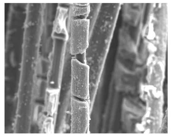
The SEM investigations of S4 and E4 before and after polarization in Asgharzadeh et al. [12] showed a destruction of the impregnation material. There was not investigated, whether the sizing under the impregnation was affected or not. To this end, the UC sample is examined in the present study. Figure 5a shows the unpolarized carbon fibre. On the right the polarized carbon fibre is shown (Figure 5b). The carbon fibres are round and have slight longitudinal grooves. This shows cracks in the sizing both in the longitudinal and in the radial direction at regular distances. The carbon fibre underneath seems to be intact. Such a clear destruction of the sizing was observed at several carbon fibres. It is concluded that the sizing deteriorates and the carbon fibre remains intact.
An energy dispersive X-ray spectroscopy (EDX) of the polarized sample probing the deposition shows the presence of calcium, carbon and oxygen (Figure 6).
4.2. Potentiostatic Tests
4.2.1. Epoxy Impregnated Carbon (E4)
No optical changes could be detected on the carbon textile E4 after the potentiostatic polarization at level 1. The epoxy resin impregnation remained even, smooth and shiny. The specimen of level 2 shows isolated areas on which the surface is mat and rough and the structure of the carbon textile is recognizable as well as white deposits indicating the chemical bonds between carbon, calcium and oxygen. These deposits become more significant with increasing polarization, which can be seen at Figure 7 right at level 3 of potentiostatic polarization.
Figure 8 shows the SEM images of the carbon fibre E4 without polarization and after the polarization. No pores can be seen on the entire reference specimen (Figure 8a) in contrast to previous findings [12]. There were only a few of them, as well as defects. Apart from impurities and a mechanical crack, the surface is smooth due to the sample preparation. In some places the carbon fibres shine through the impregnation. The epoxy resin layer does not appear to be uniformly thick. Epoxy resin was used in various test series to interrupt conductivity [10,13,14,15,16]. Van Nguyen et al. [17] have found that the embedding of carbon anodes with epoxy resin was not successful due to insufficient conductivity.
Due to the pores, defects and the different thickness of the impregnation, it can be explained why the epoxy resin-impregnated carbon fibres are polarizable at all. The potentiostatic test at level 1 did not cause any change in the surface (Figure 8b). The image of the specimen polarized at level 2 (Figure 8c) shows grooves next to two mechanical cracks and is covered approximately in half with a crystalline deposited film. Calcium, oxygen and carbon could be detected in the coating by EDX analysis. The grooves run along the carbon fibres over which the epoxy resin impregnation is probably thinnest and are due to the destruction of the impregnation. Pores have occasionally formed in the epoxy resin unlike the accumulation of pores in Asgharzadeh et al. [12]. As with the unimpregnated carbon fibres, for the carbon fibres with epoxy resin impregnation destruction in panel area 2 is used, whereas no destruction was observed in panel area 1. Thus, the start of the destruction of the epoxy resin matrix could again be in the transition range between about 1050 and 1150 mV.
The specimen of the polarization at level 3 (Figure 8d) is almost completely covered with the crystalline deposited film. There are undamaged areas that are not covered with deposited film. This and individual damages between the film indicate that most damages are obstructed by the film. Hence, it can be assumed that the damage is more pronounced than at level 2.
4.2.2. Carbon Coated with SBR-based Material (S4)
The SBR-impregnated carbon S4 has a smooth and glossy surface before polarization. Overall, the surface remains glossy but is no longer smooth but rough. The specimens of levels 2 and 3 are mostly mat and rough, there are only a few glossy surfaces left. In addition, an increased resolution of the impregnation in the area of the intersection points can be observed (Figure 9).
Figure 10 shows the SEM images of the SBR-impregnated carbon fibre S4, the surface of the reference (Figure 10a) is mostly smooth apart from impurities. Sometimes the carbon fibres shine through; there are randomly arranged pores of different sizes. In the reference specimen, there are also imperfections of different sizes from 20 µm, at which the carbon fibres are exposed. Rubber is known to be non-conductive. The pores and imperfections in the impregnations as well as the poor adhesion between SBR impregnation and carbon fibre explain why the SBR-impregnated carbon fabric also shows polarizability. After the polarization at level 1, destructions are already visible at isolated points where carbon fibres are exposed (Figure 10b). Around these areas is a white coating that looks different. According to EDX analysis, this consists mainly of carbon and oxygen and low intensities of calcium and silicon can also be detected. Overall, significantly more carbon fibres are visible due to the impregnation, which suggests that the impregnation dissolves over a large area. A destruction of the SBR impregnation therefore already occurs in panel area 1.
With increasing polarization both, the amount of deposited material and the removed surface of the impregnation increase. The impregnations already show imperfections and pores before polarization, so that a liquid electrolyte can enter the roving. Due to the poor adhesion between SBR and carbon fibre, this is particularly pronounced for the SBR-impregnated material and explains its good polarizability compared to carbon with epoxy resin impregnation. By destruction the impregnations, underlying carbon fibres come into contact with the electrolyte and increase the effective surface area with increasing dissolution. In Figure 10c a filament can be seen, which has become free and transverse cracks are recognizable, which can be either in impregnation or in carbon fibre. Figure 10d also shows a filament, which is free of impregnation. On the basis of this picture one can say exactly that with anodic polarization this filament is attacked here and cracks developed, which do not come from the production.
Dissolution of the carbon fibres could not be achieved by the potentiostatic tests. Before the carbon fibres are dissolved, the impregnations and the sizing are first destroyed. This can be explained by the fact that the carbon fibre consists of mainly covalent carbon compounds in contrast to the impregnations and the size and the covalent bond has a higher bonding energy. Since no optical changes have occurred with E4 and S4 despite significant decomposition of the impregnation materials, destruction of the impregnation materials to carbon dioxide and calcium carbonates can be assumed. Visible decomposition particles have only formed as a result of the decomposition of the sizing of the unimpregnated carbon fibres. However, the exact composition of these particles could not be determined, since the freeze-dried residual solution consisted mainly of calcium carbonate. Calcium carbonate is formed by the reaction of calcium hydroxide with carbon dioxide:
However, the carbon dioxide can be a product of carbon from the dissolution reactions as well as from the air.
4.2.3. Unimpregnated Carbon with Sizing (UC)
On most specimens, optical changes could already be detected after polarization. Photos of all specimens from the potentiostatic tests with unimpregnated carbon fibres are shown in Figure 11. The unimpregnated carbon fibres were glossy and soft, comparable to a brush before the test was carried out. After polarization at level 1, the carbon fibre is still soft but less shiny. This could be explained by the deposits of calcium carbonate. The solution of the tests at levels 1 and 2 showed no difference. The solution of the experiment at level 3, on the other hand, was discoloured brown and small black particles floated in the solution. The particles deposited on the ground after a few days. These sediments were freeze-dried with a small remainder of the solution and identified as calcium carbonate by Fourier transform infrared spectroscopy. Since the substance, unlike pure calcium carbonate, was not white but grey, further components must be present. However, these could not be detected by infrared spectroscopy.
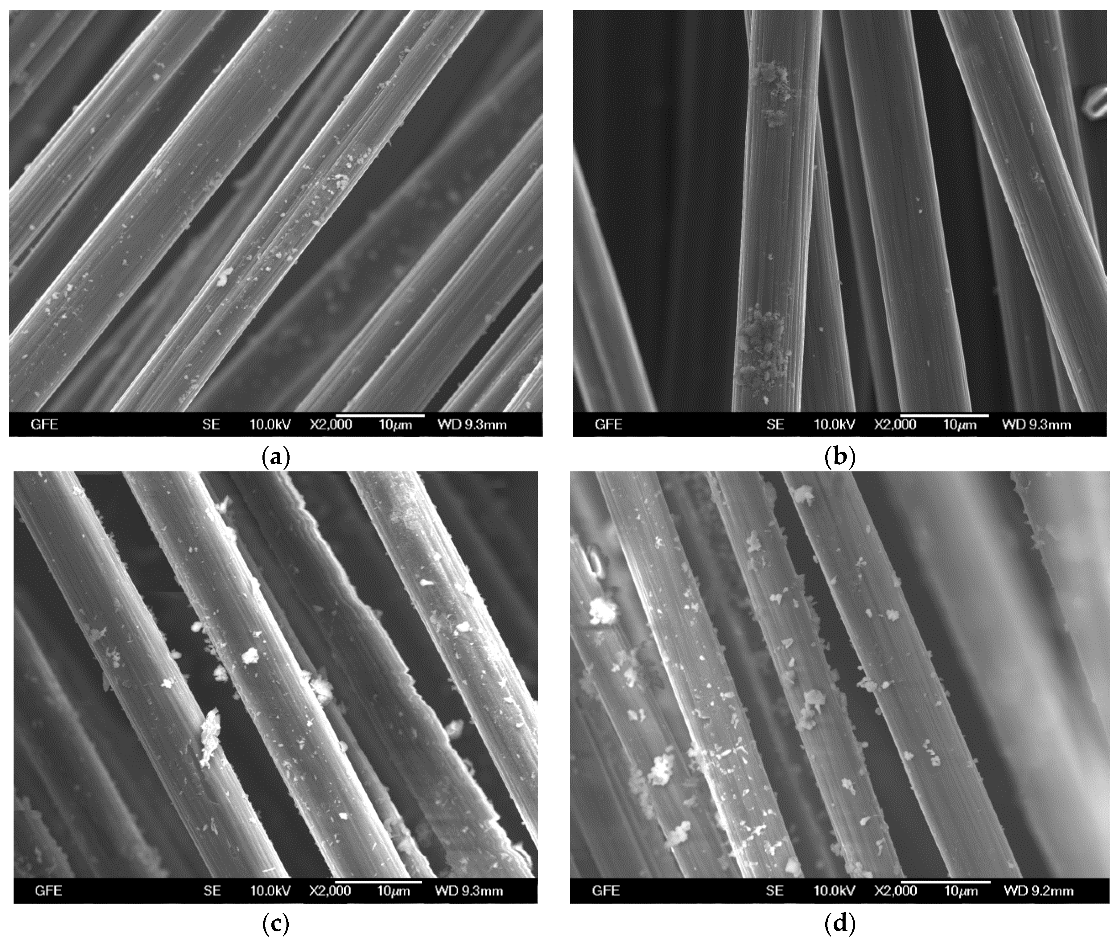
Figure 12 shows the SEM images of UC specimens. The unimpregnated carbon fibres show no damage after polarization at level 1 (Figure 12b). Slight longitudinal grooves can already be observed at the reference (Figure 12a) and no consequence of polarization. Differences in contrast, especially in bright white areas, are caused by charges from the electron ray with insufficient surface conductivity. After polarization at level 2, the sizing of many fibres is decomposed (Figure 12c). This can be seen in most fibres through the formation of deep but narrow longitudinal furrows. Cracks in the radial direction also occur in some fibres, as they have already been detected in the potentiostatic tests. This means that an anodic polarization on level 2 decomposes the size of unimpregnated carbon fibres. On level 1 no destruction of the coating was observed. The change in the slope in the current potential diagram in the phase of the transition range at approximately 900 mV versus NHE is therefore probably due to the reaction that sets in. The sizing of most carbon fibres polarized at level 3 shows very clear destruction phenomena in the form of radial cracks (Figure 12d). The decomposition of the sizing of the unimpregnated carbon fibres also took place inside the roving. It can therefore be assumed that all carbon fibres conduct electricity and are in direct contact with the electrolyte. The effective surface area of the unimpregnated carbon fibres should raise after destruction of the sizing.
In Figure 12d it is questionable, whether this destruction is in carbon or in sizing. Because the damaged layer looks thick and the residual cross section of carbon small, this question had to be examined more closely. Three further methods were used to investigate it in more detail.
(1) Examination of the average diameter of fibres in a roving
The examination of the diameter of unimpregnated carbon showed that the fibres have a diameter between 5 and 10 µm. Figure 12d shows that the diameter of carbon, under the deposited film around the fibre, is 6 µm and therefore in the range of diameters of unpolarized samples. Hence, no destruction of the carbon fibre is observed. This has been confirmed with several samples.
(2) EDX examination of the deposited film
EDX analysis was performed on an unimpregnated carbon (UC), in a region, where the deposited film was partly flaked off. So both sides of the film could be analysed.
Figure 13 and Figure 14 show that the inner part of the destroyed layer consists mainly of carbon, which could be part of the sizing. The outer layer indicates the presence of calcium, carbon and oxygen. These are the deposits formed due to chemical reaction between calcium of the solution and carbon from the sizing. These deposits can be found more strongly on the surface of the carbon as the polarization potential increases.
(3) Investigation of an unimpregnated carbon without sizing (UC_WS)
Thermal gravimetric analysis (TGA)
First, TGA measurements were performed to be sure that the two unimpregnated samples with and without sizing were different and to identify whether the sample UC really has a sizing. Since the differences cannot be seen from the SEM, TGA measurements were performed to see if the weight changes with increasing temperature. From the Figure 15 it can be seen that the sample UC_WS, which has no sizing, shows no change in mass at elevated temperature. The curve of UC shows that at 300 °C the weight decreases. This indicates that the sizing begins to dissolve. The comparison of the two curves shows that the sizing has about 1 wt% of the total weight of the carbon filament. After 450 °C, it stabilizes to 600 °C and then the curve drops again. From there the carbon textiles could start to decompose. It can be assumed that the examined UC samples with sizing really have a sizing and that the destroyed layer in Figure 12d is the sizing including deposited film.
The decrease in the weight of sample UC-WS up to 600 °C could be due to the combustion of impurities and dirt.
4.2.4. Unimpregnated Carbon without Sizing (UC_WS)
For comparison purposes, potentiostatic measurements were also carried out on unimpregnated carbon without sizing at the same potentiostatic potentials.
The SEM pictures in the Figure 16 confirm the statement that the pictures in Figure 12 show the destruction of the sizing. The unimpregnated carbon fibres without sizing show no damage after polarization at level 1 to 3. Slight longitudinal grooves can already be observed on all samples and are not a consequence of polarization. Differences in contrast, especially bright white areas, are caused by charges from the electron beam with insufficient surface conductivity. After polarization at level 2 (Figure 16c), the deposition can be seen on the surface, which is slightly increased at level 3 (Figure 16d). But, the deposition is not as strong as with the samples with sizing. It can therefore be concluded that the deposit adheres better to sizing material than carbon. No cracks or damage can be seen on any fibres. This means that anodic polarization does not destroy carbon.
There are no other test results available in the literature, therefore the test results cannot be compared.
5. Conclusions and Outlooks
Until now, it was unclear up to which potentials the impregnation materials and the sizing remain undamaged by anodic polarization. The results contribute to the clarification of these questions for the investigated materials.
The results show that the operation of CP with carbon textiles as anode material leads to deterioration of the polymer impregnations and sizing. Since impregnation and sizing are available to increase the strength capacity of carbon textiles, the deterioration of these materials is very interesting. With epoxy impregnated carbon it is possible to use carbon textiles as CP anode without destroying the epoxy and sizing up to the mentioned potentials.
With the increasing polarization, the strength of the deposited film on the sizing increases.
The conclusion of this work can be summarized as follows:
- The investigations in solution have shown that CP with investigated carbon anodes up to 2200 mV versus NHE is possible
- The Carbon filaments within the Carbon textiles as CP anode have not been destroyed up to the investigated potentials up to 2200 mV versus NHE.
- With SBR impregnated samples, the impregnation is destroyed right from the start during polarization.
- The sizing is destroyed at a potential of about 900 mV versus NHE.
- Epoxy impregnation started to destroy between 1050 and 1150 mV versus NHE.
Further tests must be carried out to investigate the bond between polymer impregnated carbon textiles and mortar. It must be observed whether the destruction of the impregnation or sizing has a negative influence on the bond or durability.
Author Contributions
Conceptualization, A.A. and M.R.; Methodology, A.A.; Software, A.A.; Validation, A.A.; Formal Analysis, A.A.; Investigation, A.A.; Resources, A.A. and M.R.; Data Curation, A.A.; Writing—Original Draft Preparation, A.A.; Writing—Review & Editing, A.A. and M.R.; Visualization, A.A.; Supervision, M.R.
Funding
This research received no external funding
Conflicts of Interest
The authors declare no conflict of interest.
References
- Gao, S.L.; Mäder, E.; Plonka, R. Nanostructured coatings of glass fibres: Improvement of alkali resistance and mechanical properties. Acta Mater. 2007, 55, 1043–1052. [Google Scholar] [CrossRef]
- Zhang, R.L.; Huang, Y.D.; Liu, L.; Tang, Y.R.; Su, D.; Xu, L.W. Effect of emulsifier content of sizing agent on the surface of carbon fibres and interface of its composites. Appl. Surf. Sci. 2011, 257, 3519–3523. [Google Scholar] [CrossRef]
- Lesko, J.J.; Swain, R.E.; Cartwright, J.W.; Chin, J.W.; Reifsnider, K.L.; Dillard, D.A.; Wightman, J.P. Interphases developed from fibre sizings and their chemical-structural relationship to composite performance. J. Adhes. 1994, 45, 43–57. [Google Scholar] [CrossRef]
- Xu, L. Interfacial Engineering of the Interphase between Carbon Fibers and Vinyl Ester Resin. Ph.D. Thesis, Department of Chemical Engineering and Materials Science, Michigan State University, East Lansing, MI, USA, 2003. [Google Scholar]
- Broyles, N.S.; Verghese, K.N.E.; Davis, S.V.; Li, H.; Davis, R.M.; Lesko, J.J.; Riffle, J.S. Fatigue performance of carbon fibre/vinyl ester composites: The effect of two dissimilar polymeric sizing agents. Polymer 1998, 39, 3417–3424. [Google Scholar] [CrossRef]
- Wetjen, D. Wechselwirkung von Carbonfasern, Schlichte und Epoxidbasierter Polymerer Matrix in Carbonfaserverstärkten Kunststoffen. Ph.D. Thesis, Mathematisch-Naturwissenschaftlich-Technische Fakultät, Universität Augsburg, Augsburg, Germany, 2016. [Google Scholar]
- Poltavtseva, M.; Ebell, G.; Mietz, J. Electrochemical investigations of carbon-based conductive coatings for application as anodes in ICCP systems of reinforced concrete structures. Mater. Corros. 2015, 66, 627–634. [Google Scholar] [CrossRef]
- Rueffer, M.; Bejan, D.; Bunce, N.J. Graphite. An active or an inactive anode? Electrochim. Acta 2011, 56, 2246–2253. [Google Scholar] [CrossRef]
- Chung, D.D.L. Review Graphite. J. Mater. Sci. 2002, 37, 1475–1489. [Google Scholar] [CrossRef]
- Asgharzadeh, A.; Raupach, M.; Koch, D. Investigations on the Suitability of Technical Textiles for Cathodic Corrosion Protection. In Proceedings of the 4th International Conference on Concrete Repair, Rehabilitation and Retrofitting (ICCRRR), Leipzig, Germany, 5–7 October 2015. [Google Scholar]
- Asgharzadeh, A.; Raupach, M. Development of a test Method for the Durability of Carbon Textiles under Anodic Polarisation. In Service Life and Durability of Reinforced Concrete Structures (RILEM Book Series); Springer International Publishing: Basel, Switzerland, 2018; pp. 143–158. [Google Scholar]
- Asgharzadeh, A.; Raupach, M. Durability behaviour of polymer impregnated carbon textiles in alkaline solution as CP anode. Mater. Corros. 2018, 1–12. [Google Scholar] [CrossRef]
- Bertolini, L.; Bolzoni, F.; Pastore, T.; Pedeferri, P. Effectiveness of a conductive cementitious mortar anode for cathodic protection of steel in concrete. Cem. Concr. Res. 2004, 34, 681–694. [Google Scholar] [CrossRef]
- Chini, M.; Antonsen, R.; Vennesland, Ø.; Mork, J.H.; Arntsen, B. Polarization Behavior of Carbon Fiber as an Anodic Material in Cathodic Protection. In Proceedings of the 11DBMC International Conference on Durability of Building Materials and Components, Istanbul, Turkey, 11–14 May 2008. [Google Scholar]
- Chini, M. Pan-Based Carbon Fiber as Anode Material in Cathodic Protection Systems for Concrete Structures. Avhandling–Norges Teknisk-Naturvitenskapelige Universitet, Trondheim. Ph.D. Thesis, Department of Structural Engineering, Faculty of Engineering Science and Technology, Norwegian University of Science and Technology, Trondheim, Norway, 2010. [Google Scholar]
- Zhang, E.Q.; Tang, L.; Zack, T. Carbon Fiber as Anode Material for Cathodic Prevention in Cementitious Materials. In Proceedings of the 5th International Conference on the Durability of Concrete Structures, Shenzhen, China, 30 June–1 July 2016; Xing, F., Han, N., Zhu, J.-H., Eds.; Shenzhen University: Shenzhen, China; Purdue University Press: West Lafayette, IN, USA, 2016. [Google Scholar] [Green Version]
- Van Nguyen, C.; Lambert, P.; Mangat, P.; O’Flaherty, F.; Jones, G. The Performance of Carbon Fibre Composites as ICCP Anodes for Reinforced Concrete Structures. ISRN Corros. 2012, 2012, 1–9. [Google Scholar] [CrossRef]
Figure 1.
Formation of surface oxides in graphite [7].
Figure 1.
Formation of surface oxides in graphite [7].

Figure 2.
Specimen with S4 anode, spacers and titanium electrode (a) and an E4 anode (b).
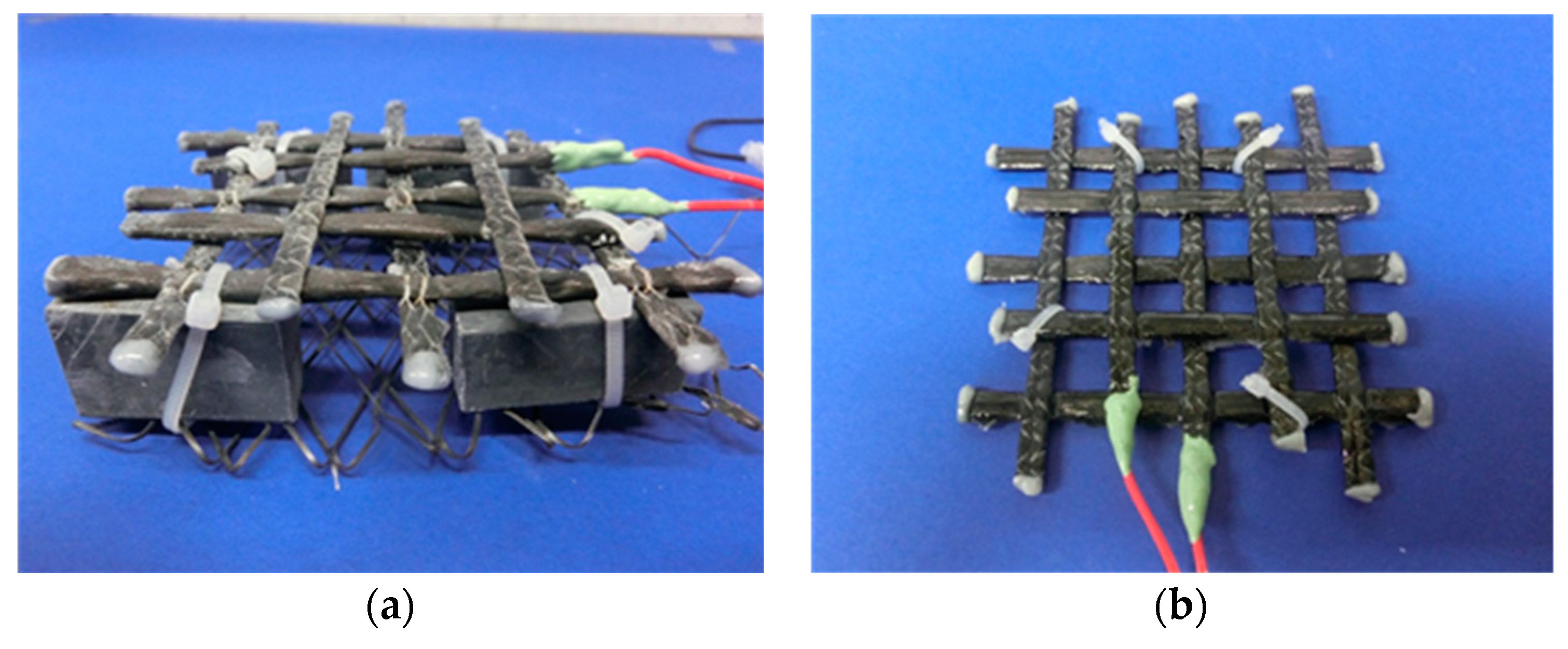
Figure 3.
Current-potential curve for all materials.

Figure 4.
Unimpregnated carbon fibres before the test (a) and after (b).
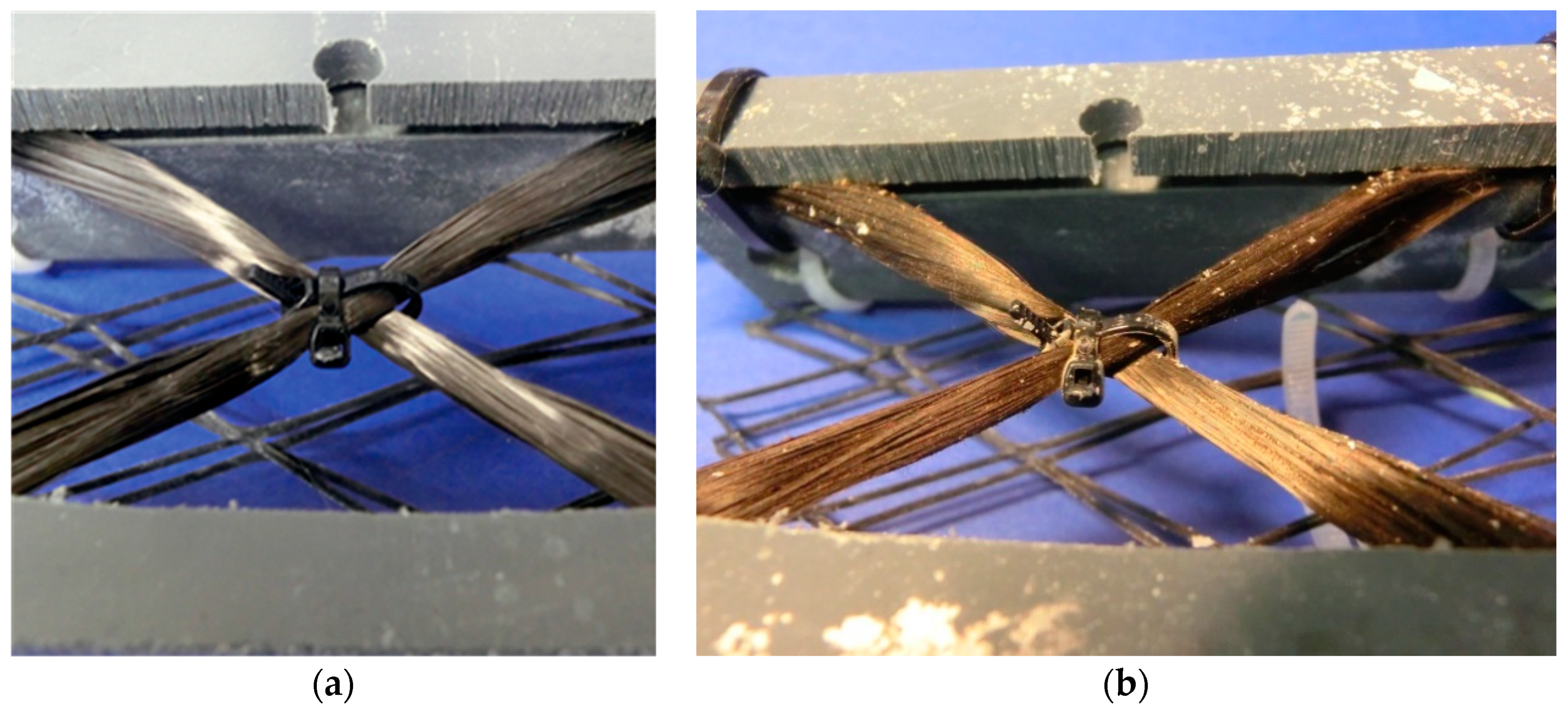
Figure 5.
SEM images of unpolarized carbon fibres (a) and a polarized carbon fibre (b).
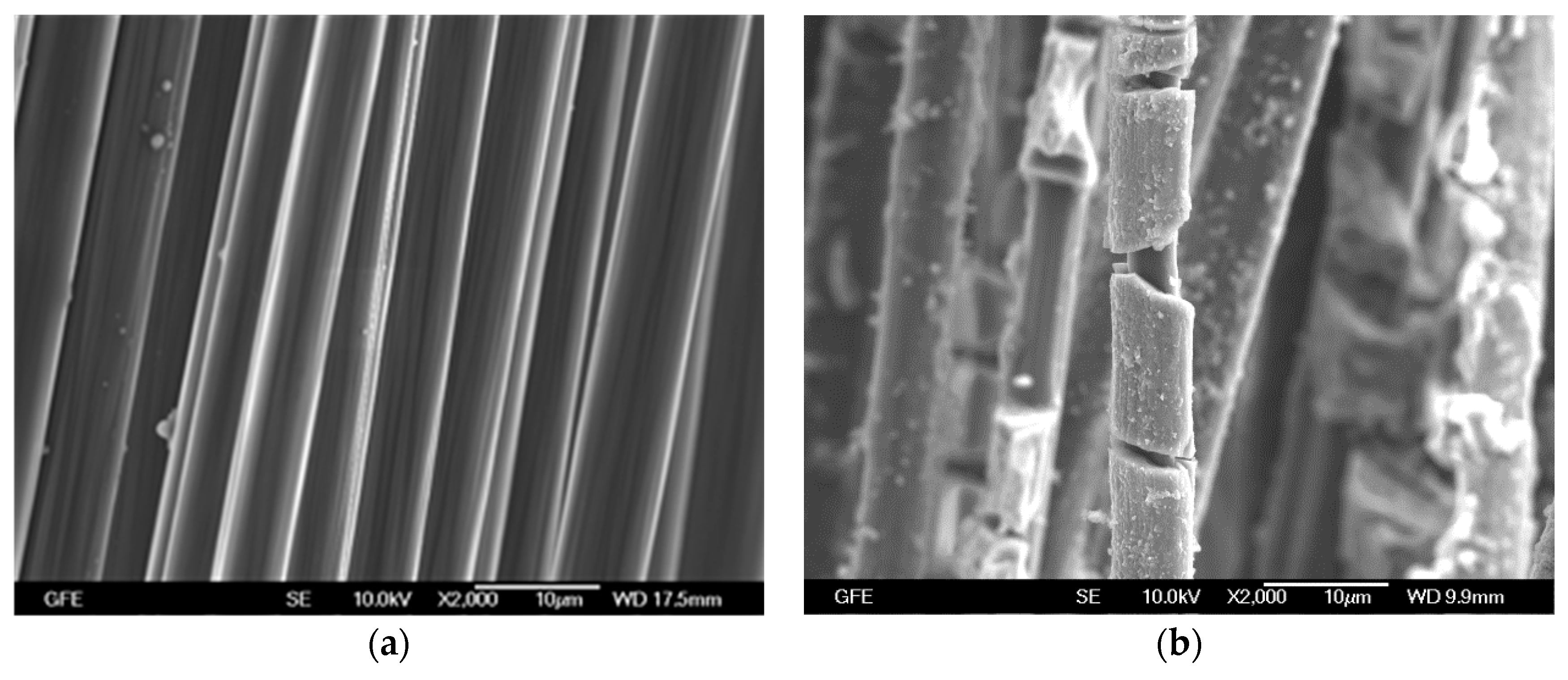
Figure 6.
EDX analysis of the deposited film.

Figure 7.
From left to right: Anodes E4 of levels 1 to 3 after polarization.

Figure 8.
SEM images of E4: unpolarized reference (a), after polarization at level 1 (b), level 2 (c) and level 3 (d).
Figure 8.
SEM images of E4: unpolarized reference (a), after polarization at level 1 (b), level 2 (c) and level 3 (d).
Figure 9.
From left to right: S4 anodes of stages 1 to 3 after polarization.
Figure 10.
SEM images of S4: unpolarized reference (a), after polarization at level 1 (b), level 2 (c) and level 3 (d).
Figure 10.
SEM images of S4: unpolarized reference (a), after polarization at level 1 (b), level 2 (c) and level 3 (d).

Figure 11.
From left to right: specimen P1 of levels 1 to 3 after polarization.
Figure 12.
SEM images of UC: unpolarized reference (a), after polarization at level 1 (b), level 2 (c) and level 3 (d).
Figure 12.
SEM images of UC: unpolarized reference (a), after polarization at level 1 (b), level 2 (c) and level 3 (d).
Figure 13.
SEM image of unimpregnated carbon. 1 and 2 EDX analysis in the marked area.
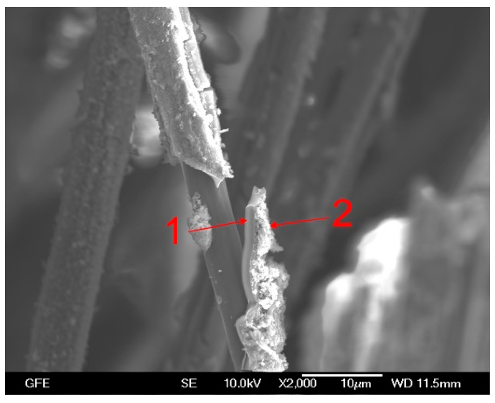
Figure 14.
EDX analysis in the marked area 1 (a) and EDX analysis in the marked area 2 (b).
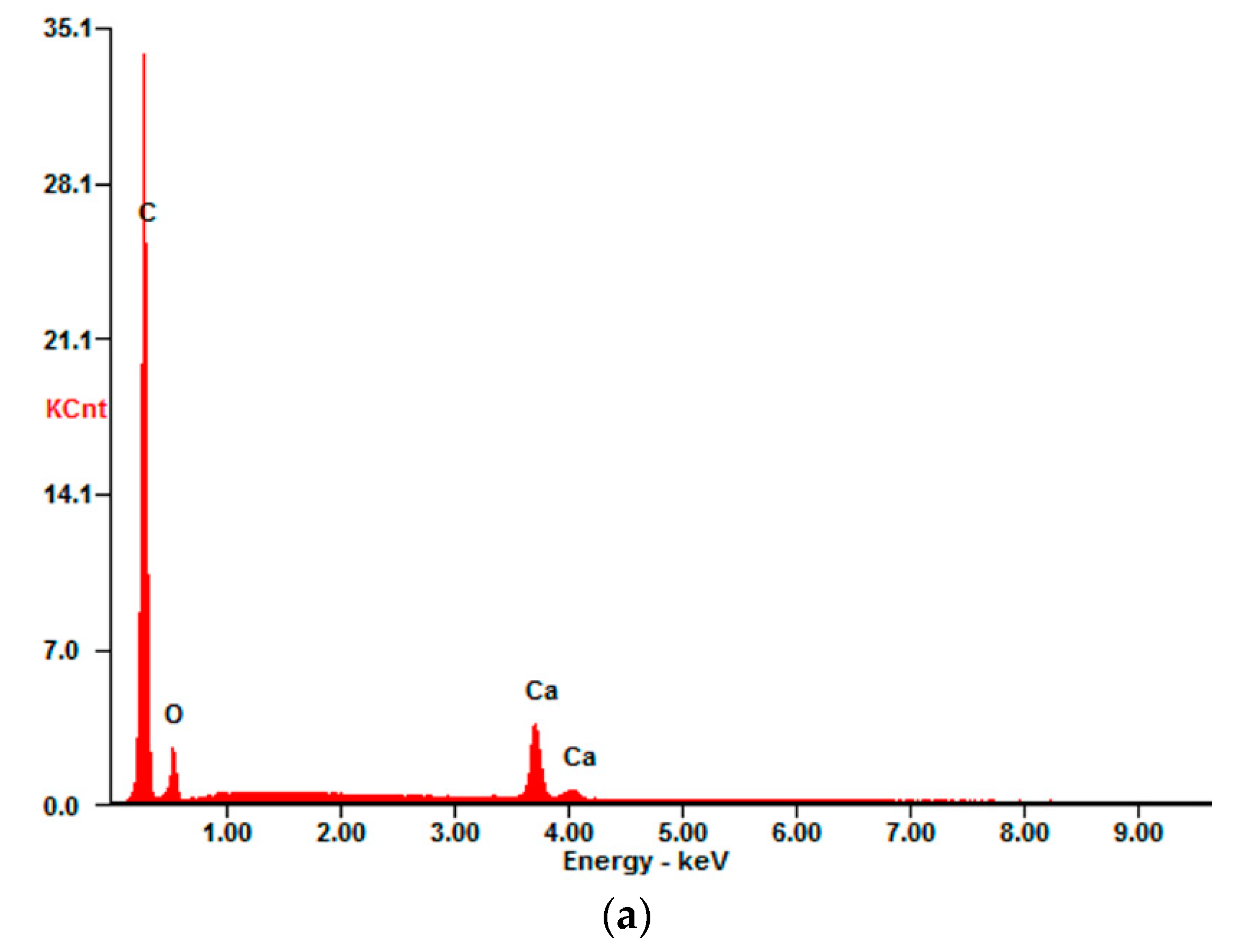

Figure 15.
TGA measurement of both unimpregnated Carbons.

Figure 16.
SEM images of UC_WS: unpolarized reference (a), after polarization at level 1 (b), level 2 (c) and level 3 (d).
Figure 16.
SEM images of UC_WS: unpolarized reference (a), after polarization at level 1 (b), level 2 (c) and level 3 (d).

Table 1.
Details of carbon textiles used in the investigations.
| Specimen Specification | Sizing | Impregnation Material | Mesh Size [mm/mm] 0°/90° | |
|---|---|---|---|---|
| impregnated carbon textile | E4 | yes | Epoxy | 38/38 |
| S4 | yes | SBR | 38/38 | |
| unimpregnated carbon textile | UC | yes | - | - |
| UC_WS | no | - | - |
Table 2.
Potentiostatic potentials on level 1, 2 and 3.
| Material | Level 1 | Level 2 [mV] vs. NHE | Level 3 |
|---|---|---|---|
| E4 | 940 | 1490 | 1940 |
| S4 | 490 | 1490 | 1840 |
| UC | 690 | 1300 | 1940 |
| UC_WS | 690 | 1300 | 1940 |
© 2018 by the authors. Licensee MDPI, Basel, Switzerland. This article is an open access article distributed under the terms and conditions of the Creative Commons Attribution (CC BY) license (http://creativecommons.org/licenses/by/4.0/).
Share and Cite
MDPI and ACS Style
Asgharzadeh, A.; Raupach, M. Damage Mechanisms of Polymer Impregnated Carbon Textiles Used as Anode Material for Cathodic Protection. Appl. Sci. 2019, 9, 110. https://doi.org/10.3390/app9010110
AMA Style
Asgharzadeh A, Raupach M. Damage Mechanisms of Polymer Impregnated Carbon Textiles Used as Anode Material for Cathodic Protection. Applied Sciences. 2019; 9(1):110. https://doi.org/10.3390/app9010110
Chicago/Turabian StyleAsgharzadeh, Amir, and Michael Raupach. 2019. "Damage Mechanisms of Polymer Impregnated Carbon Textiles Used as Anode Material for Cathodic Protection" Applied Sciences 9, no. 1: 110. https://doi.org/10.3390/app9010110
Note that from the first issue of 2016, this journal uses article numbers instead of page numbers. See further details here.