Article

Optimizing C-RAN Backhaul Topologies: A Resilience-Oriented Approach Using Graph Invariants

by
Valerio Frascolla
1,*,
Cristina K. Dominicini
2,
Marcia H. M. Paiva
3,
Gilles Caporossi
4,
Marcelo Antonio Marotta
5,
Moises R. N. Ribeiro
3,
Marcelo E. V. Segatto
3,
Magnos Martinello
2,
Maxwell E. Monteiro
3 and
Cristiano Bonato Both
6
1
Intel Communication and Devices Group, Intel Deutschland GmbH, Am Campeon 10-12, 85579 Neubiberg, Germany
2
Software Defined Networks Research Group, Department of Informatics, Federal University of Espírito Santo—UFES, Av. Fernando Ferrari, 514, Vitória 29075-910, Espírito Santo, Brazil
3
LabTel (Laboratory of Telecommunications), Department of Electrical Engineering, Federal University of Espírito Santo—UFES, Av. Fernando Ferrari, 514, Vitória 29075-910, Espírito Santo, Brazil
4
GERAD & HEC Montréal, 3000, Chemin de la Côte-Sainte-Claire, Montréal, QC H3T 2A7, Canada
5
Institute of Informatics—Federal University of Rio Grande do Sul, Av. Bento Gonçalves 9500, Porto Alegre 91501-970, Rio Grande do Sul, Brazil
6
Exact and Applied Social Sciences Department (DECESA), Federal University of Health Sciences of Porto Alegre, Rua Sarmento Leite, 245, Porto Alegre 90050-170, Rio Grande do Sul, Brazil
*
Author to whom correspondence should be addressed.
Appl. Sci. 2019, 9(1), 136; https://doi.org/10.3390/app9010136
Submission received: 30 October 2018 / Revised: 18 December 2018 / Accepted: 25 December 2018 / Published: 2 January 2019

Abstract

:
At the verge of the launch of the first commercial fifth generation (5G) system, trends in wireless and optical networks are proceeding toward increasingly dense deployments, supporting resilient interconnection for applications that carry higher and higher capacity and tighter latency requirements. These developments put increasing pressure on network backhaul and drive the need for a re-examination of traditional backhaul topologies. Challenges of impending networks cannot be tackled by star and ring approaches due to their lack of intrinsic survivability and resilience properties, respectively. In support of this re-examination, we propose a backhaul topology design method that formulates the topology optimization as a graph optimization problem by capturing both the objective and constraints of optimization in graph invariants. Our graph theoretic approach leverages well studied mathematical techniques to provide a more systematic alternative to traditional approaches to backhaul design. Specifically, herein, we optimize over some known graph invariants, such as maximum node degree, topology diameter, average distance, and edge betweenness, as well as over a new invariant called node Wiener impact, to achieve baseline backhaul topologies that match the needs for resilient future wireless and optical networks.

1. Introduction

Notwithstanding the constant evolution of telecommunication networks and the new set of features appearing at each new release of the 3GPP (3rd Generation Partnership Project) standard specifications [1], mobile terminal users still do not experience the promised stable, seamless, and high-throughput connectivity when moving around. That is why the telecommunication ecosystem is on the verge of launching the fifth generation of telecommunication networks (5G), which will deploy a series of notable innovations that will implement the edge network paradigm to support very high traffic volume, higher data rate, lower latency, and increased reliability in both heterogeneous and dense scenarios [2].
As such, 5G represents an evolution of more classical network paradigms with new demands on backhaul networks [3] that must be able to carry several heterogeneous radio access technologies to power data centers. Notably, the concept of Cloud-Radio Access Networks (C-RAN) employs optical backhaul for transfer of radio signals for direct processing in data centers, with minimal processing at base stations. Therefore, C-RAN represents one of the most demanding use cases for backhauling in 5G, and is the focus of our work in this paper.
Cheaper radio equipment composed solely by array of antennas, digital to analog converters, and usually an optical wired interface, also known as Remote Radio Head (RRH), will gradually replace current radio base stations in C-RAN. The RRHs have the ability to upload all their sampled signal workload to be processed at cloud data-centers, also known as Baseband Unit (BBU) pools. Far from the edge of the network, BBU pools centralize the processing of workload, thus allowing for several benefits such as better energy consumption, simpler synchronization, and less complicated implementations of recent features, e.g. coordinated multipoint (CoMP). Considering 5G and C-RAN literature, some authors make a clear distinction between the network interconnecting BBUs and RRHs, calling it fronthaul, and the network interconnecting BBUs and the core network, calling it backhaul, whereas other authors merge the fronthaul and the backhaul terms [4]. In this paper, we adopt this second terminology, considering the entire optical network that connects the C-RAN elements as the backhaul network.
A C-RAN approach to backhaul design is hampered by four main challenges:
  • High link capacity demands: The workload transmitted from RRH to BBU requires a massive quantity of data to be represented, i.e. samples at rates from 0.6–24.3 Gbps for each RRH antenna using the Common Public Radio Interface (CPRI) protocol or even higher when considering its successor eCPRI (enhanced CPRI) [5].
  • Scalability limitations: C-RAN systems are envisioned to accommodate the workload of high density RANs in BBU pools, ranging from 100 to 1000 RRHs, which demands intricate approaches to designing and managing a large number of data streams and processing points.
  • Strict latency requirements: The workload of RRHs must be processed in time for any responses to be transmitted from the RRH, in accordance with the radio protocol definition [6]. For example, given the processing of the Hybrid Automatic Repeat reQuest (HARQ) protocol, the RRHs workload must be processed within 3 ms to meet protocol requirements [7].
  • Survivability: C-RAN systems must provide guarantees about the degree to which operation can remain unaltered during element failure or unexpected events; that is, C-RAN must offer some level of survivability [8].

1.1. Survivability and Resilience in C-RAN Backhaul Networks

In case of failures or unexpected events, a C-RAN is supposed to both continue basic operations and deliver some degree of quality in doing so. That is, the nature of C-RAN backhauling demands that a BBU is both able to communicate with its associated RRHs and that it does so in accordance with the radio protocols employed at the RRH. A basic definition of resiliency would simply require that the backhaul of a C-RAN includes a set of paths that support communication between every BBU and RRH pair after f failures. Instead, we prefer the notion of resilience, which requires that after f failures there is a “good” set of paths that enables communication between every pair. We conjecture that the notion of resilience better captures the survivability requirements of C-RAN backhaul than the more basic formulation.
Given this notion of survivability for C-RAN backhauls, we also distinguish between the properties of basic survivability and resilience in backhaul networks. Here, we describe these properties in the case that f = 1 , but the concept extends to any number of failures. Basic network survivability is guaranteed by 2-connectivity between nodes, which means that the graph remains connected even in the case of a single link or node failure. Noting that latency provides the primary requirement for the goodness of C-RAN backhaul, we consider a network to be resilient if it has two disjoint paths of limited length connecting any pair of nodes. Thus, the survivability is guaranteed by the 2-connectivity and the operation in accordance with radio protocols after failure is guaranteed because the diameter and the average distance (and, consequently, the latency) are bounded after a failure.
Survivability in C-RAN and resiliency in 5G networks have been investigated in literature (see [3,9,10,11]). Existing models tend to include this notion into the consideration of other problems, such as: (i) a BBU placement problem; or (ii) a control function split problem. In the former, proposals highlight that a better positioning of BBUs in the network would enable a distribution of the processing capabilities of a C-RAN to tackle latency and scalability issues, as well as achieve better survivability in the case of unexpected delay occurrence. In the latter, the radio protocol functionalities are split between BBUs and RRHs, based on the trade-off between the rate required by the underlying infrastructure and the degree to which processing may be inserted at the edge of the C-RAN. As a secondary effect of optimizing this split of functionalities, both the link capacity and the latency requirements are eased, in turn improving the margin for absorption of failures. Consequently, the survivability of C-RAN networks optimized in such a manner is improved. Finally, it is worth mentioning that, to the best of our knowledge, the existing works reduce the C-RAN backhaul topology planning to a cost optimization problem, as explained in the next section, and do not exploit resilience and survivability properties of the underlying topologies. Extending beyond such works, we assume a broader perspective on survivability by examining the properties intrinsically associated to the topology planning and refining of backhauling to achieve increased survivability in C-RANs.

1.2. A Resilience-Oriented Approach Using Graph Invariants for C-RAN Backhaul Design

The design of communication networks has been discussed for decades. There is a consensus in the literature on treating this problem as a multi-objective optimization problem [12,13,14,15,16,17], which maps aspects such as cost, performance, and survivability into constraints. Whereas this consensus suggests a common methodology for network design, it reduces the design problem to a general cost optimization formulation, where the topology is a mere input of this problem, neglecting the role of the topology properties as a relevant component of the solution. Nevertheless, several works have shown how the topology has great impact on network capabilities, such as fault tolerance [18,19], resource consumption (i.e., number of wavelengths) [20,21], and throughput [22].
C-RAN backhaul topologies can also be planned considering capacity [23] and energy consumption [24]. Moreover, in scenarios where CAPEX and OPEX can be decreased, the backhaul is planned considering the possibility of sharing links through the usage of already installed metropolitan optical networks and other underused fiber in a city [25]. In this case, our main novelty is to improve reliability and survivability of the network by optimizing link selection according to intrinsic topology properties, instead of optimizing capacity or energy consumption.
In this paper, we propose a method for systematic refinement of existing optical networks toward service of C-RAN backhaul, grounded in graph theoretic optimization. Our approach leverages graph invariants to quantify the requirements of wireless networks and constraints of backhauling infrastructure.
A graph invariant is a measure that characterizes the topological structure of a graph, and does not depend on the labels of its nodes. One of the most studied graph invariants is the Wiener index, proposed in 1947 [26] with the purpose of estimating the boiling point of alkane molecules. This graph invariant gave rise to hundreds of topological indices in the field of mathematical chemistry [27,28]. Interestingly, the same invariant was independently proposed 40 years later in [29], motivated by communication network problems. Graph invariants have been used since 1993 for designing novel chemical compounds [30,31]. However, to the best of our knowledge, this is the first time a work applies graph invariants to the design of backhaul communication networks.
Graph invariants provide the means to capture several important features of a backhaul topology, including the number of nodes or edges as well as the maximum degree of nodes, the topology diameter, and the average distance (or average hop count). Note that these invariants do not depend on the specific technology adopted by the backhauling network and instead focus on the structure of the topology. Importantly, this aspect of invariants enables their use in determining the fundamental ability of a backhaul topology to meet latency and resilience requirements. Moreover, a grounding in graph theory enables the use of mature tools.
Therefore, a basis in graph theory enables our approach to provide fundamental insight into the ability of a backhaul design to meet the requirements of wireless network and systematically refine this ability. Through refining existing optical network topologies in service of C-RAN backhaul, we jointly consider the needs of wireless networks and the associated optical operation. More specifically, we investigate how C-RAN backhaul resilience requirements can be expressed in terms of the graph invariants described in the literature. Furthermore, we propose a new distance-based graph invariant, called Wiener impact, which is related to resilience aspects of the backhaul topology design.
The main contributions of this paper can be summarized as follows: (i) study of C-RAN backhaul requirements related to resilience; (ii) investigation of graph invariants described in the literature that can capture such requirements; (iii) design of a new graph invariant (Wiener impact) related to backhaul resilience; and (iv) proposal of a method for backhaul design as a graph optimization problem.
This paper is organized as follows. In Section 2, we describe our method, map C-RAN resilience requirements into existing graph invariants, and propose the new Wiener impact invariant. Some case studies of the proposed method are presented in Section 3. Section 4 finally draws our conclusions and points at future research directions.

2. Backhaul Design as a Graph Optimization Problem

In this paper, we argue that the problem of designing backhaul topologies using graph theory can be stated as determining means of linking a given number n of nodes, where both wireless objectives and backhauling constraints are expressed in terms of graph invariants. In this way, the network topology design can be seen as a graph optimization problem. The mathematical formulation of this problem is fully described in [32]. The definitions of all the graph invariants used in this work can be found in Appendix A.
In the design of any backhaul network, the most basic constraint is that each element of the system has to be connected to the network; in graph theoretic terms, at least one path must connect each pair of nodes, resulting in the network being a connected graph. This requirement outlines a search space for our optimization. The size of this space grows rapidly with the number of nodes considered within a network: there are 853 possible connected graphs with seven nodes and if we simply double the number of nodes, this number grows to 29,003,487,462,848,061 [33]. Such a rapid growth of search space prevents an exhaustive search for telecommunication topologies. The problem when dealing with C-RAN is even more acute, given the dynamicity that sets C-RAN apart, mainly due to the fact that the graph often changes, where RRHs can be dynamically associated to a different BBU pool when the backhaul becomes overloaded, preventing pre-processing techniques to be applied.
Adding constraints related to interconnection of backhauling elements further bounds our search space. For example, the practical constraint of the number of communication interfaces that may be deployed maps into a limitation of the size of a topology. Alternatively, the number of communication interface edges supported by any single node may be constrained through limiting the degree of nodes. Applied in this manner, additional invariants provide the means to restrict the search on the basis of the interconnection constraints of a backhaul network to meet specific network requirements. Even during dynamic changes occurring in C-RAN, the graph invariants remains as a rule to be followed preventing the aforementioned problem.
Section 2.1 discusses how the resilience requirements of C-RAN backhaul could be mapped to a set of graph invariants. Although this paper focuses on invariants that can capture network metrics related to resilience in C-RAN backhaul, the method proposed here can be applied to any network requirement that can be mapped to a graph invariant. Thus, Section 2.2 outlines a generic method for backhaul design as a graph optimization problem.

2.1. Mapping C-RAN Resilience Requirements to Graph Invariants

Once the constraints of potential backhaul interconnection have defined a space, wireless objectives may be mapped into graph theoretic terms to guide a search. For example, the concept of betweenness of an edge e in a graph G measures the proportion of the number of shortest paths among all node pairs in G that pass through e; as such, this invariant can be used as measurement of potential network congestion. As another example, since latency is fundamentally limited by propagation delay, the diameter and the average distance invariants provide the means to describe the fundamental latency performance of a network. Minimization of these invariants finds topologies with the highest potential for supporting wireless networks with strict latency requirements. On the usage of the betweenness invariant, the latency requirements for C-RAN, such as posed by the HARQ protocol, can be better managed defining the exactly topology, which would give the best survivability in case of backhaul overloads, preventing C-RAN to lose connectivity and performance.
Alternatively, the resilience requirements of a wireless network can be described in terms of the effect of alterations to a topology. For example, traditional tree topologies lack fault tolerance due to collapse upon loss of any edge or non-leaf node. A need for survivability may be translated into the search for k-connected graphs, where the value of k is proportional to the level of backhaul fault tolerance required by the wireless network. Given the dynamic capabilities of C-RAN to readjust the RRHs workload distribution to BBU pools on the fly, changing the communication topology to achieve better fault tolerance is not just feasible, but is also required. Therefore, to enhance survivability, the C-RAN topology can be reconfigured online through different graph invariants to achieve better fault tolerance and resilience.
By describing backhaul interconnection constraints and wireless objectives in this manner, our approach allows the refinement of existing topologies to address novel challenges. For example, the traditional ring topology is commonly used for its fault tolerance, but exhibits undesirable latency properties. Specifically, the ring topology has the maximum diameter of all 2-connected graphs with n nodes [29] and the diameter of a ring increases from n / 2 to n 1 after the removal of any edge.
Our approach proposes the refinement of the ring topology allowing it to be more suitable for supporting wireless networks with tight latency requirements. In this case, we may constrain our search space to contain only topologies with two disjoint paths for each pair of nodes, while minimizing the diameter of the resultant topology. To this end, we propose a new invariant called the node Wiener impact, which provides a measure for a 2-connected graph G of the impact on the distances between node pairs in the remaining graph when a node v is removed. This new node invariant is based on well-known invariants: the node transmission [29] and the graph Wiener index [26].
The Wiener index of a given graph is the half sum of its distance matrix, which represents the total number of hops that are necessary to interconnect all pair of nodes using the shortest path between them. If the load is homogeneously distributed among all the node pairs and the routing algorithm considers the shortest paths, this invariant gives an idea of the cost to route data in a network: the lower is the Wiener index, the more likely is a network to route data using fewer hops. The transmission of a node, on the other hand, is the sum of the distances from this node to all other nodes. In an ideal solution, all the distances remain the same after a vertex removal and, consequently, there are at least two disjoint geodesics interconnecting any pair of nodes. This can be achieved if the Wiener index of the resultant graph is equal to the Wiener index of the original graph subtracted by the transmission of the removed vertex, for any vertex of the graph. Formalizing this idea, the node Wiener impact of a node v in a 2-connected graph G, denoted as τ v , is defined as:
τ v = W ( G v ) W ( G ) + T ( v ) ,
where W ( G ) is the Wiener index of the original graph G, W ( G v ) is the Wiener index of the graph obtained by removing v from G, and T ( v ) is the transmission of the node v.
Therefore, the Wiener impact can be used as a more robust way of measuring network resilience in 2-connected networks: the lower is the Wiener impact of a node, the lower is the growth of the distances between node pairs in the resultant graph when that node is removed. In our approach, we consider that a network is resilient if it has two disjoint paths of limited length connecting any pair of nodes. For more information on betweenness, Wiener index, and transmission, one can refer to [34].

2.2. Backhaul Design Method

Our approach offers an extensible method for backhaul design, which means that additional constraints or objectives may be represented through the incorporation of new invariants to the graph optimization problem. The development of new graph invariants increases the power of our approach to backhaul design in the direction of capturing desirable topological properties. For instance, it is possible to design backhaul networks that prioritize power minimization or energy consumption, whenever these physical quantities can be expressed by appropriated graph invariants.
Table 1 summarizes the above discussion by showing the mapping of some common network features into graph invariants.
Figure 1 presents our proposed method. The first step is to define the network requirements that will guide the topology design (e.g., low latency, resilience, and nodes have up to four communication interfaces). Then, these requirements are mapped into graph invariants that are described in the literature. For instance, average latency can be mapped to average distance, and the maximum number of interfaces can be mapped to maximum node degree. If it is possible to map all the requirements, then the next step is to create an optimization model. Otherwise, it is necessary to design new invariants that can capture the outstanding network requirements. One example is the design of the Wiener impact invariant, described in the previous section, for capturing the resilience requirement.
When all the requirements are mapped, it is possible to define constraints and objective functions in terms of graph invariants. For example, the problem of finding a resilient network with low latency, where nodes have a maximum of four communication interfaces, could be stated as: minimize the Wiener impact and the average distance, subject to a 2-connected graph of maximum degree less than or equal to four. Finally, this graph optimization problem can be solved using a integer linear programming (ILP) method or heuristics. In our case, we use Variable Neighborhood Search (VNS) heuristic with the help of the AutoGraphiX III (AGX) software [32,35], as explained in the next section. The result of this optimization process is the interconnection topology itself.
After defining a candidate topology that meets the defined network requirements, one may run other optimization steps to guarantee capacity allocation using the topology and the traffic matrix as inputs. For example, the problem may be stated as the minimization of the operational cost represented by bandwidth usage or processing power. Afterwards, this solution can be tested in a prototype, simulated or emulated environment, and analyzed against a set of network metrics (e.g., flow completion time and traffic distribution among nodes). If the results are satisfactory, the solution may be deployed in production networks. Otherwise, it may be necessary to redefine the network requirements and execute the design method of Figure 1 again.

3. Case Studies

In this section, we present some case studies of backhaul topology design using graph optimization. To support invariants computation and graph optimization, we selected the AGX (Available at https://www.gerad.ca/Gilles.Caporossi/agx) software in [32,35]. Initially, we examined tree topologies, which are still very popular in access networks due to their low cost. Although they do not offer survivability, we used this simple architecture to illustrate how graph optimization can lead to better topological solutions for meeting C-RAN future network requirements. We then moved on to investigate ring-based networks, which offer survivability but not resilience, showing how graph optimization can improve them. Finally, a real-world network topology was studied to show the practical implications of graph optimization in the decision making process regarding the C-RAN underlying topology design.

3.1. Non-Survivable Topologies: Trees

This first case study focused on node interconnection and latency requirements. Table 2 collects the invariants values of the proposed topologies.
In the search for topologies for a network with 19 nodes, basic interconnection constraints and a minimal latency objective could be addressed with a classic star topology (tree graph family), as shown in Figure 2a, which contains only 18 edges (low edge cost), has diameter 2 (low maximum latency), has average distance 1.89 (low average latency), and has Wiener index 324. Unfortunately, analysis showed that this topology is highly dependent on a central node (maximum degree is 18, and degree variance is 14.41 ), whose removal stops the communication between all other nodes. Moreover, the high maximum degree brings implementation barriers.
Although a high centralized topology would bring some impacts to the network interconnectivity, for C-RAN, such centralization would be perfect for reusing the resources at data-centers. The more centralized a BBU pool is positioned, the bigger is the potential to receive offloaded workload from other RANs to be processed in the same BBU pools. It means that the operator would not have to spend too much revenue with new BBU pools by reusing the already deployed ones.
Despite the benefits that C-RAN would afford from such topology, to minimize the centralization impacts, an expert could propose the solution shown in Figure 2b [36]. This solution effectively reduces the maximum degree and the degree variance from 18 to 4 and from 14.41 to 1.67 , respectively, with the downside of increasing the diameter from 2 to 6, and increasing the Wiener index from 324 to 544.
Our method allows the further systematic refinement of even the expert’s solution. From the solution presented in Figure 2b and using AGX, our approach obtains the graph shown in Figure 2c. The optimization applied here minimizes the diameter and the average distance, subject to maximum degree less than or equal to four. The maximum degree constraint ensures that the gains originally achieved by the expert are maintained. The result of this optimization only changes one edge to reduce the diameter from 6 to 5 while keeping almost all other invariants, with the only disadvantage of slightly increasing the load on some edges (maximum edge betweenness goes from 70 to 78, and degree variance goes from 1.67 to 1.78 ). Alternatively, we could consider different objective functions and constraints to improve other topological parameters. For example, if the constraint on the maximum degree is not so critical to the network design, we could use maximum degree less than or equal to five to reduce the diameter to 3. That is, our approach to topology design enables the systematic exploration of potential topologies and enumeration of major trade-offs.

3.2. From Survivable to Resilient Topologies: 2-Connected Graphs

This second case study focused on survivability requirements. Information on the invariants values of the proposed topologies can be found in Table 3.
At first sight, the search for resilient topology solutions for a network with 14 nodes could lead to the 2-connected ring topology shown in Figure 3a, which contains only 14 edges and has average degree 2 (low cost). However, as discussed in Section 2, the ring is a poor solution considering latency and resilience requirements, because the diameter is high (7, in this case) and changes to 13 in case of any node removal. Moreover, given a fixed number of nodes, the ring is the 2-connected graph maximizing the Wiener index [29]. For a ring with 14 nodes, the Wiener index is 343, and the node Wiener impact of each of its nodes is 70.
With the goal of minimizing these impacts, an expert could propose the solution shown in Figure 3b [37], which attempts to combine the benefits from ring and star topologies. This solution reduces the latency related invariants (the average distance, from 3.77 to 1.71 , and the diameter, from 7 to 2) and the Wiener index by adding 12 edges from each node to a central node. On the other hand, its benefits are still dependent on a single node, which is related to the high values for maximum degree (13) and degree variance ( 6.63 ). The maximum and minimum values for Wiener impact (130 and 0, respectively) also demonstrate the significance of removing this central node on the transmission of the other nodes and, thus, show that the solution is not resilient.
Once again our solution supports the refinement of this topology to address its faults. Starting with the solution presented in Figure 3b and using AGX, we obtained the graph shown in Figure 3c. Here, the optimization minimizes the Wiener impact, and the average distance, subject to a 2-connected graph of both diameter and maximum degree less than or equal to four. The number of edges is also fixed to 26, which allows a fair comparison between both solutions with respect to interconnection parameters. The maximum degree constraint is an example requirement from [36]. Our optimized solution has few drawbacks: the average distance goes from 1.71 to 2.04 , the diameter goes from 2 to 3, and the Wiener index goes from 156 to 186. On the other hand, it has great positive impact on the maximum degree (from 13 to 4) and the degree variance (from 6.63 to 0.20 ). Moreover, our method heavily improves the topology resilience as shown by the reduction on the maximum Wiener impact (from 130 to 6).
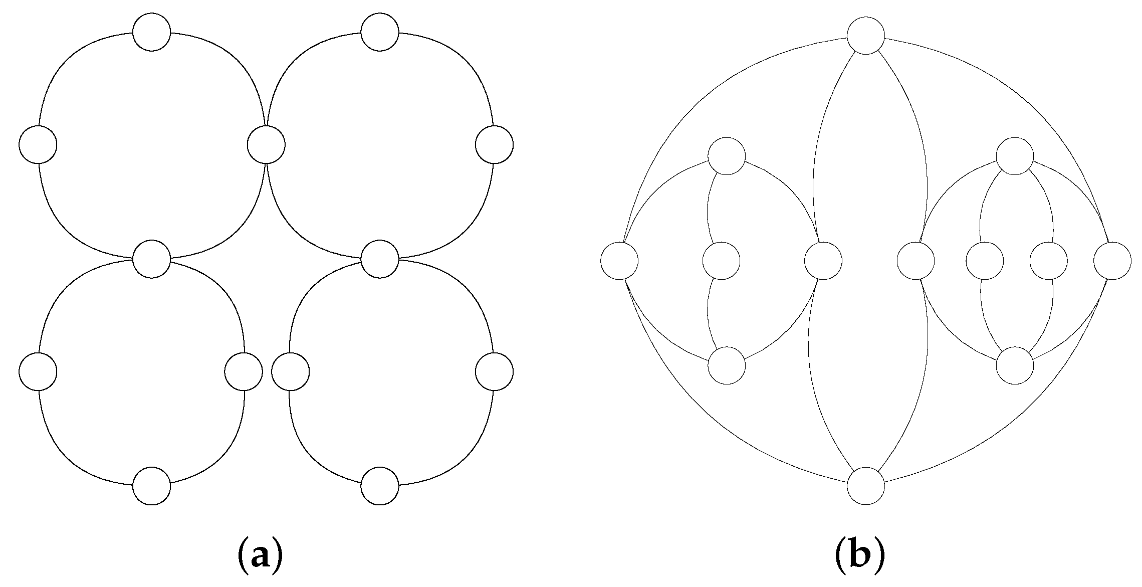
Extending the previous analysis, we investigate C-RAN topologies, which are typically composed by hierarchical ring structures [38], as shown in Figure 4a. This structure is not a 2-connected graph and leads to poor resilience properties, since the removal of a single node that interconnects two rings produces a disconnected graph.
We optimized the C-RAN topology presented in Figure 4a using AGX to improve resilience, and obtained the graph shown in Figure 4b. The graph optimization problem can be stated as: minimize the Wiener impact, and the average distance, subject to a 2-connected graph of diameter less than or equal to 6 and maximum degree less than or equal to four.
Table 4 compares the hierarchical ring topology with the optimized one, which has much better resilience properties. As the topology based on hierarchical rings is not a 2-connected graph, it is not possible to calculate its Wiener impact (i.e., some nodes have infinite Wiener impact, since some node pairs become unreachable after a single node removal). On the other hand, in our optimized topology, any node removal still produces a connected graph. Moreover, this topology minimizes the Wiener impact for our problem, and has very special resilience properties, because it is a twin graph, with working and backup paths of equal length for all nonadjacent node pairs [39]. This can be verified by the fact that both the maximum and minimum node Wiener impact are zero, meaning that after any node removal there is still another path of equal cost that can replace a path that contains the faulty node.
The only drawback of our optimized solution is the increase of the number of edges from 16 to 22, which also affects the average degree. All other invariants are maintained or improved, including the average distance (from 2.72 to 2.49 ). In particular, our method heavily improves the topology resilience and provides a much more adequate topology for C-RAN requirements, which justifies the cost of adding extra edges.

3.3. From Survivable to Resilient Topologies: A Real-World Network

In C-RAN, its underlying infrastructure presents two problems: (i) massive initial investment; and (ii) ossified infrastructure. In the former, BBU pools need to be connected to RRHs using redundant optical links (e.g., ring links) that require site installation and long length links (e.g., ≥10 km) per antenna, hindering the centralization of BBU pools due to high cost. In the latter, the underlying infrastructure after installed cannot be easily repositioned needing new investments and man-working, compromising the scalability of C-RAN. Based on these problems, reusing already deployed underlying infrastructure (backhaul) enables the cut of initial investments also giving new possibilities of deployment, merging C-RAN’s underlying infrastructure with backhaul.
Although the reuse of the backhaul is crucial to the realization of C-RAN, the survivability of such hybrid underlying infrastructure may be compromised, mainly because of the different already deployed infrastructure purposes, such as interconnecting cities or providing connectivity to Internet Service Providers. Therefore, the goal of this case study is to extend our resilience analysis to a real-world backbone network in the realization of C-RAN. To this end, we optimize the Brazilian National Research and Educational Network (RNP) topology (Available at www.pop-sc.rnp.br/servicos/conectividade), which is composed by 28 points of presence. Since the resilience analysis only makes sense in a 2-connected graph, Figure 5 shows the representation of the resultant 25-node topology after the removal of the three nodes that are not part of any cycle. Information on the invariants values of the proposed topologies can be found in Table 5.
An analysis of Figure 5 shows that the highlighted nodes have high Wiener impact values (181 and 146), which tell us that the impact on the overall network resilience of removing these nodes is high. This diagnosis can drive an expert to connect extra edges in the network to reduce the impact of their disconnection. For example, in the graph of Figure 6a, the addition of only two extra edges (highlighted in red dashed lines) to the original graph of Figure 5 reduces the maximum Wiener impact from 181 to 69. This example shows how the analysis of node invariants can be used as an incremental and informed method for increasing network resilience in an existing network that does not support disruptive changes.
On the other hand, if the goal is to design a new topology from scratch that focuses on resilience, we could fix the original number of nodes (25) and edges (38) and try to minimize the maximum Wiener impact. With this objective function and these constraints in AGX, we were able to find the topology shown in Figure 6b that presents a maximum Wiener impact value of 34 (against the original 181 value of the original topology). We can also check in Table 5 that all the other analyzed invariants were improved when compared to the original topology.
To better understand the effects of minimizing the node Wiener impact on the topological parameters, a worst case analysis was performed for the same topologies analyzed in Table 5. For that end, for each topology, the node maximizing the Wiener impact was removed from the topology, and the invariants were computed again. The results are presented in Table 6. Notice that, whereas the diameter of the original topology has increased from 5 to 9 after the worst case node failure, the diameter of both the improved topologies has only increased from 5 to 6. Moreover, the average distance of these improved topologies increases much less ( 11.68 % for the topology shown in Figure 6a and 5.43 % for the one shown in Figure 6b) than the average distance of the original topology ( 25 % ). These results are graphically presented in Figure 7. In addition, this figure shows that the diameter and the average distance invariants from the optimized topology of Figure 6b are similar to the topology of Figure 6a, but without the need for adding two additional edges.
When we optimize the original graph, the output is an improved node interconnection solution that better suits the defined constraints and objective functions. A final step to implement the solution in real networks is to map the nodes from the optimized solution into the original node geographical distribution. This is another problem that can also be tackled with the guidance of graph invariants. For example, a heuristics may sort the original geographical nodes by traffic load or population aspects and map them to the nodes in the optimized solution that have the greater values for some specific graph invariant (e.g., degree or Wiener impact). In addition, this heuristics has to ensure that neighbors in the optimized solution are close in terms of geographic distance to minimize the cabling costs.

4. Conclusions and Future Research Directions

In this paper, we propose a method for designing resilient backhaul topologies, based on graph invariants. We also proposed a new invariant, the node Wiener impact, which measures the impact of a node failure to the distances among the remaining node pairs. Besides, we are currently working on a version of the node Wiener impact invariant for analyzing the impact of link failures.
As demonstrated herein, our graph theoretic approach to backhaul topology design enables the systematic refinement of backhaul topologies on the basis of wireless network objectives. Furthermore, our method enables the direct comparison of topologies and examination of the trade-offs in network design. Moreover, this manner of designing network topologies allows us to bring the large knowledge base available within the graph theory community to overcome telecommunications challenges.
In summary, our solution could provide guidance in the decision making about the impacts on the network when new entities (edges and nodes) are added or removed in the topology. For the C-RAN, this is fundamental to raising the survivability and making feasible the usage of the backhaul as part of the C-RAN underlying infrastructure.
This work can be extended in many ways. For instance, to implement the interconnection solutions obtained by our method, an important practical aspect to be further studied is the embedding of the nodes of a improved solution into the nodes of the original solution. In addition, one could use the interconnection solution as the basis to design an ILP model that takes into account traffic demands.
Another interesting investigation direction is the extension of our method for multi-layered network design. In C-RAN context, we devise problems with the sharing of physical resources, such as fibers and optical equipment, between backhaul and fronthaul networks. In this scenario, two overlay networks with distinct objectives impact the physical topology planning.
An additional future objective is to explore how our method behaves in dynamically allocated scenarios, such as heterogeneous cloud radio access network (H-CRAN) [7]. In this problem, we must consider the on/off switching of the RRH unities, and the dynamic BBUs and RRHs re-association. In this direction, our proposal can also benefit from the SDN/NFV paradigm for managing and orchestrating network topology according to dynamic demands [40].

Author Contributions

Following the philosophy of funded collaborative research project, this work was a joint contribution of all mentioned authors. The efforts to devise, implement and produce the results were spent during the work of the EU–Brazil co-funded research project called FUTEBOL (Federated Union of Telecommunications Research Facilities for an EU-Brazil Open Laboratory) [41]. In general, the following can be said: writing—original draft, C.K.D., M.H.M.P., G.C., M.A.M., M.R.N.R., M.E.V.S., M.M., M.E.M. and C.B.B.; and writing—review and editing, V.F.

Funding

This work was part of the FUTEBOL project, which has received funding from the European Union’s Horizon 2020 for research, technological development, and demonstration under grant agreement No. 688941 (FUTEBOL), as well from the Brazilian Ministry of Science, Technology and Innovation (MCTI) through RNP and CTIC. This study was also financed in part by CNPq, FAPES, and the Coordenação de Aperfeiçoamento de Pessoal de Nível Superior—Brasil (CAPES)—Finance Code 001.

Conflicts of Interest

The authors declare no conflict of interest. The funders had no role in the design of the study; in the collection, analyses, or interpretation of data; in the writing of the manuscript, or in the decision to publish the results.

Appendix A. Definitions

This appendix defines the main graph theory concepts used in this paper. Basic concepts not defined here follow the definitions of Harary [42].
Definition 1 (Graph, G = G ( V , E ) ).
A graph G = G ( V , E ) consists of a set V = V ( G ) of vertices or nodes, and a set E = E ( G ) of edges or links, where each edge u v connects a pair of vertices u , v G . The order of G is n = n ( G ) = | V ( G ) | , and the size of G is m = m ( G ) = | E ( G ) | .
Definition 2 (Connected graph).
A graph G is connected if there is at least one path between each pair of vertices u , v V ( G ) .
Definition 3 (k-connected graph).
A graph is k-connected if and only if there are at least k vertex-disjoint paths between each pair of vertices u , v V ( G ) .
Definition 4 (Vertex degree).
The number of edges incident to a vertex v V ( G ) defines the degree of v.
Definition 5 (Geodesic or shortest path).
The shortest path (in number of hops) connecting two vertices u , v V ( G ) is called a u v geodesic.
Definition 6 (Distance between two vertices).
The distance between two vertices u and v in a connected graph G, denoted as d i s t ( u , v ) , is the length of a geodesic between u and v in G.
Definition 7 (Graph distance matrix).
Let G be a connected graph of order n. The distance matrix of G is an order n matrix such that:
D i s t [ i , j ] = d i s t ( v i , v j ) , v i , v j V ( G ) , i j ; 0 , o t h e r w i s e .
Definition 8 (Graph diameter).
The diameter of a connected graph G is the length of the greatest geodesic in G. More formally, it is given by:
d i a m ( G ) = max { d i s t ( u , v ) ; u , v V ( G ) } .
Definition 9
(Vertex ransmission [29]). Let G be a connected graph. The transmission of a vertex v V ( G ) is defined as:
T ( v ) = u V ( G ) d i s t ( u , v ) .
Definition 10
(Graph Wiener index [26]). Let G be a connected graph. The Wiener index of G is given by:
W ( G ) = u V ( G ) v V ( G ) , v < u d i s t ( u , v ) .
Definition 11 (Graph average distance).
The average distance of a connected graph G is the Wiener index of G over the number of pairs of vertices in G.
Definition 12 (Node Wiener impact).
Let G be a 2-connected graph. The Wiener impact of a vertex v V ( G ) is defined as:
τ v = W ( G v ) W ( G ) + T ( v ) ,
where G v refers to the graph obtained by removing v from G.
Definition 13 (Edge betweenness).
The betweenness of an edge u v E ( G ) is given by:
b u v = k V ( G ) l V ( G ) , k < l s u v k l s k l ; u v E ( G ) ,
where s u v k l is the number of geodesics between vertices k and l ( k < l ) passing through edge u v , and s k l is the total number of geodesics between k and l.

References

  1. Raaf, B.; Faerber, M.; Badic, B.; Frascolla, V. Key technology advancements driving mobile communications from generation to generation. Intel Technol. J. 2014, 18, 12–28. [Google Scholar]
  2. Andrews, J.G.; Buzzi, S.; Choi, W.; Hanly, S.V.; Lozano, A.; Soong, A.C.K.; Zhang, J.C. What Will 5G Be? IEEE J. Sel. Areas Commun. 2014, 32, 1065–1082. [Google Scholar] [CrossRef]
  3. NetWorld2020 ETP. 5G: Challenges, Research Priorities, and Recommendations. Joint White Paper; NetWorld2020. 2014. Available online: https://networld2020.eu/wp-content/uploads/2015/01/Joint-Whitepaper-V12-clean-after-consultation.pdf (accessed on 28 December 2018).
  4. Jaber, M.; Imran, M.A.; Tafazolli, R.; Tukmanov, A. 5G Backhaul Challenges and Emerging Research Directions: A Survey. IEEE Access 2016, 4, 1743–1766. [Google Scholar] [CrossRef]
  5. Common Public Radio Interface (CPRI). Interface Specification V7.0; Ericsson, A.B., Ed.; Huawei Technologies Co. Ltd, NEC Corporation, Alcatel Lucent, and Nokia Networks: Shenzhen, China, 2015. [Google Scholar]
  6. Alyafawi, I.; Schiller, E.; Braun, T.; Dimitrova, D.; Gomes, A.; Nikaein, N. Critical issues of centralized and cloudified LTE-FDD Radio Access Networks. In Proceedings of the 2015 IEEE International Conference on Communications (ICC), London, UK, 8–12 June 2015; pp. 5523–5528. [Google Scholar]
  7. Peng, M.; Li, Y.; Jiang, J.; Li, J.; Wang, C. Heterogeneous Cloud Radio Access Networks: A New Perpective for Enhancing Spectral and Energy Efficiency. IEEE Wirel. Commun. 2014, 21, 126–135. [Google Scholar] [CrossRef]
  8. Dharmaraja, S.; Jindal, V.; Varshney, U. Reliability and Survivability Analysis for UMTS Networks: An Analytical Approach. IEEE Trans. Netw. Serv. Manag. 2008, 5, 132–142. [Google Scholar] [CrossRef]
  9. Douik, A.; Dahrouj, H.; Al-Naffouri, T.Y.; Alouini, M. Resilient backhaul network design using hybrid radio/free-space optical technology. In Proceedings of the 2016 IEEE International Conference on Communications (ICC), Kuala Lumpur, Malaysia, 22–27 May 2016; pp. 1–7. [Google Scholar] [CrossRef]
  10. Ramamurthy, S.; Sahasrabuddhe, L.; Mukherjee, B. Survivable WDM Mesh Networks. J. Light. Technol. 2003, 21, 870. [Google Scholar] [CrossRef]
  11. Khorsandi, B.M.; Tonini, F.; Raffaelli, C. Design methodologies and algorithms for survivable C-RAN. In Proceedings of the 2018 International Conference on Optical Network Design and Modeling (ONDM), Dublin, Ireland, 14–17 May 2018; pp. 106–111. [Google Scholar] [CrossRef]
  12. Flores, S.D.; Cegla, B.B.; Cáceres, D.B. Telecommunication network design with parallel multi-objective evolutionary algorithms. In Proceedings of the 2003 IFIP/ACM Latin America Conference on towards a Latin American Agenda for Network Research, La Paz, Bolivia, 3–5 October 2003; pp. 1–11. [Google Scholar]
  13. Gerla, M.; Kleinrock, L. On the topological design of distributed computer networks. IEEE Trans. Commun. 1977, 25, 48–60. [Google Scholar] [CrossRef]
  14. Murthy, C.S.R.; Gurusamy, M. WDM Optical Networks: Concepts, Design, and Algorithms; Prentice Hall PTR: Englewood Cliffs, NJ, USA, 2002. [Google Scholar]
  15. Ramaswami, R.; Sivarajan, K.; Sasaki, G. Optical Networks: A Practical Perspective; Morgan Kaufmann: Burlington, MA, USA, 2009. [Google Scholar]
  16. Simmons, J.M. Optical Network Design and Planning; Springer: Berlin, Germany, 2014. [Google Scholar]
  17. Hou, X.; Lin, B.; He, R.; Wang, X. Infrastructure planning and topology optimization for reliable mobile big data transmission under cloud radio access networks. EURASIP J. Wirel. Commun. Netw. 2016, 2016, 119. [Google Scholar] [CrossRef]
  18. Orlowski, S.; Wessäly, R.; Pióro, M.; Tomaszewski, A. SNDlib 1.0-Survivable network design library. Netw. Int. J. 2010, 55, 276–286. [Google Scholar] [CrossRef]
  19. Pavan, C.; de Lima, L.S.; Paiva, M.H.M.; Segatto, M.E.V. How reliable are the real-world optical transport networks? IEEE J. Opt. Commun. Netw. 2015, 7, 578–585. [Google Scholar] [CrossRef]
  20. Baroni, S.; Bayvel, P. Wavelength requirements in arbitrarily connected wavelength-routed optical networks. J. Light. Technol. 1997, 15, 242–251. [Google Scholar] [CrossRef]
  21. Pavan, C.; Morais, R.; Rocha, R.F.; Pinto, A.N. Generating realistic optical transport network topologies. IEEE J. Opt. Commun. Netw. 2010, 2, 80–90. [Google Scholar] [CrossRef]
  22. Jyothi, S.A.; Singla, A.; Godfrey, P.; Kolla, A. Measuring and understanding throughput of network topologies. In Proceedings of the International Conference for High Performance Computing, Networking, Storage and Analysis, Salt Lake City, Utah, 13–18 November 2016; IEEE Press: Piscataway, NJ, USA, 2016; p. 65. [Google Scholar]
  23. Musumeci, F.; Bellanzon, C.; Carapellese, N.; Tornatore, M.; Pattavina, A.; Gosselin, S. Optimal BBU Placement for 5G C-RAN Deployment Over WDM Aggregation Networks. J. Light. Technol. 2016, 34, 1963–1970. [Google Scholar] [CrossRef]
  24. Carapellese, N.; Tornatore, M.; Pattavina, A. Energy-Efficient Baseband Unit Placement in a Fixed/Mobile Converged WDM Aggregation Network. IEEE J. Sel. Areas Commun. 2014, 32, 1542–1551. [Google Scholar] [CrossRef]
  25. Gosselin, S.; Pizzinat, A.; Grall, X.; Breuer, D.; Bogenfeld, E.; Krauß, S.; Gijón, J.A.T.; Hamidian, A.; Fonseca, N.; Skubic, B. Fixed and Mobile Convergence: Which Role for Optical Networks? J. Opt. Commun. Netw. 2015, 7, 1075. [Google Scholar] [CrossRef]
  26. Wiener, H. Structural determination of paraffin boiling points. J. Am. Chem. Soc. 1947, 69, 17–20. [Google Scholar] [CrossRef] [PubMed]
  27. Rouvray, D.H. Chapter 2—The Rich Legacy of Half a Century of the Wiener Index. In Topology in Chemistry; Rouvray, D., King, R., Eds.; Woodhead Publishing: Sawston, UK, 2002; pp. 16–37. [Google Scholar]
  28. Todeschini, R.; Consonni, V. Handbook of Molecular Descriptors; Wiley-VCH: Weinheim, Germany, 2008. [Google Scholar]
  29. Plesník, J. On the sum of all distances in a graph or digraph. J. Graph Theory 1984, 8, 1–21. [Google Scholar] [CrossRef]
  30. Estrada, E.; Patlewicz, G.; Uriarte, E. From Molecular Graphs to Drugs. A Review on the Use of Topological Indices in Drug Design and Discovery. Indian J. Chem. 2003, 42, 1315–1329. [Google Scholar]
  31. Roy, K. Topological descriptors in drug design and modeling studies. Mol. Divers. 2004, 8, 321–323. [Google Scholar] [CrossRef] [PubMed]
  32. Caporossi, G.; Hansen, P. Variable neighborhood search for extremal graphs: 1 The AutoGraphiX system. Discret. Math. 2000, 212, 29–44. [Google Scholar] [CrossRef]
  33. OEIS. The On-Line Encyclopedia of Integer Sequences. 2010. Available online: http://oeis.org (accessed on 28 December 2018).
  34. Caporossi, G.; Paiva, M.; Vukicevic, D.; Segatto, M. Centrality and betweenness: Vertex and edge decomposition of the Wiener index. MATCH Commun. Math. Comput. Chem. 2012, 68, 293–302. [Google Scholar]
  35. Caporossi, G. Variable Neighborhood Search for Extremal Vertices. Comput. Oper. Res. 2017, 78, 431–438. [Google Scholar] [CrossRef]
  36. Cambridge Broadband Networks Limited. Backhauling X2; White Paper; Cambridge Broadband Networks Limited: Cambridge, UK, 2010. [Google Scholar]
  37. Photonics and Networking Research Laboratory. DAN: Deutsche Telekom/Stanford Next Generation Access Network. Available online: http://pnrl.stanford.edu/dan (accessed on 28 December 2018).
  38. Eramo, V.; Listanti, M.; Lavacca, F.G.; Iovanna, P. Dimensioning Models of Optical WDM Rings in Xhaul Access Architectures for the Transport of Ethernet/CPRI Traffic. Appl. Sci. 2018, 8, 612. [Google Scholar] [CrossRef]
  39. Vassoler, G.L.; Paiva, M.H.M.; Ribeiro, M.R.N.; Segatto, M.E.V. Twin Datacenter Interconnection Topology. IEEE Micro 2014, 34, 8–17. [Google Scholar] [CrossRef]
  40. Costa-Perez, X.; Garcia-Saavedra, A.; Li, X.; Deiss, T.; de la Oliva, A.; di Giglio, A.; Iovanna, P.; Moored, A. 5G-Crosshaul: An SDN/NFV Integrated Fronthaul/Backhaul Transport Network Architecture. IEEE Wirel. Commun. 2017, 24, 38–45. [Google Scholar] [CrossRef] [Green Version]
  41. FUTEBOL Project Website. Available online: http://www.ict-futebol.org.br (accessed on 28 December 2018).
  42. Harary, F. Graph Theory; Addison-Wesley Publishing Company: Philippines, PA, USA, 1969; p. 284. [Google Scholar]
Figure 1. Topology design method.
Applsci 09 00136 g001
Figure 2. Tree based topologies: (a) star; (b) expert; and (c) improved solution (AGX).
Applsci 09 00136 g002
Figure 3. 2-connected topologies: (a) ring; (b) wheel; and (c) improved solution (AGX).
Applsci 09 00136 g003
Figure 4. CRAN topologies: (a) hierarchical ring; and (b) improved solution (AGX).
Applsci 09 00136 g004
Figure 5. RNP backbone: resultant 2-connected graph with 25 nodes.
Applsci 09 00136 g005
Figure 6. Optimization of topology shown in Figure 5: (a) addition of two edges; and (b) minimization of the maximum Wiener impact.
Applsci 09 00136 g006
Figure 7. Invariants after the worst case node failure (max. WI): (a) diameter; and (b) average distance.
Applsci 09 00136 g007
Table 1. Network requirements and invariants.
FeatureInvariant
CostOrder, size, and maximum/average degree
Maximum latencyDiameter
Average latencyAverage distance
Network congestionEdge betweenness, and degree variance
Survivability2-connectivity
ResilienceNode Wiener impact
Table 2. Tree based topologies (19 nodes).
Invariants(a) Star(b) Expert [36](c) Improved Solution (AGX)
Max. degree1844
Average degree1.891.891.89
Degree variance14.411.671.78
Diameter265
Average distance1.893.183.16
Wiener index324544540
Max./Min. edge betweenness18/1870/1878/18
Table 3. 2-connected topologies (14 nodes).
Invariants(a) Ring(b) Wheel [37](c) Improved Solution (AGX)
Nr. of edges142626
Max. degree2134
Average degree23.713.71
Degree variance06.630.20
Diameter723
Average distance3.771.712.04
Wiener index343156186
Max./Min. edge betweenness24.5/24.510/212/6.5
Max./Min. node Wiener impact70/70130/06/0
Table 4. CRAN topologies (13 nodes).
Invariants(a) Hierarchical Ring [38](b) Improved Solution (AGX)
Nr. of edges1622
Max. degree44
Average degree2.463.38
Degree variance0.710.70
Diameter66
Average distance2.722.49
Wiener index212194
Max./Min. edge betweenness33.5/6.511/6.25
Max./Min. node Wiener impact0/0/0
Table 5. RNP backbone (25 nodes).
InvariantsOriginalAddition of Two EdgesMinimization of Max. WI
Nr. of edges384038
Max. degree775
Average degree3.043.203.04
Degree variance2.122.480.68
Diameter555
Average distance2.842.742.76
Wiener index852822828
Max./Min. edge betweenness55.17/6.5045.85/6.2332.74/12.33
Max./Min. node Wiener impact181/069/034/0
Table 6. RNP backbone after the worst case node failure (max. WI).
InvariantsOriginalAddition of Two EdgesMinimization of Max. WI
Nr. of edges333334
Max. degree665
Average degree2.752.752.83
Degree variance1.851.520.89
Diameter966
Average distance3.553.062.91
Wiener index979844802
Max./Min. edge betweenness97.5/6.5853.27/7.0039.38/10.83

