Article

Vibration Compensation of the Frequency-Scanning-Interferometry-Based Absolute Ranging System

State Key Laboratory of Precision Measurement Technology and Instruments, Tianjin University, Tianjin 300072, China
*
Author to whom correspondence should be addressed.
Appl. Sci. 2019, 9(1), 147; https://doi.org/10.3390/app9010147
Submission received: 5 December 2018 / Revised: 23 December 2018 / Accepted: 25 December 2018 / Published: 3 January 2019

Abstract

:
The frequency-scanning-interferometry-based (FSI-based) absolute ranging technology is a type of ranging technology possessing a high precision and no ranging blind area, so it can be used for non-cooperative targets. However, due to a tiny movement of a target, the Doppler shift and the phase modulation are introduced into the beat signal which results in ranging accuracy decrease. In order to solve this problem, first the model of vibration effect is established, and then the beat signals of two adjacent scanning periods are processed to produce a signal that is immune to vibration. The proposed method is verified by the experiments, and the experimental results show that the effect of vibration compensation is better for the target with a lower vibration velocity and at a lower vibration frequency (lower than 6 Hz). When the target is subjected to a sinusoidal vibration with an amplitude of 10 μm at a frequency of 1 Hz, by using the proposed method the standard deviation is reduced from 775 to 12 μm. Moreover, in the natural environment, by using vibration compensation the standard deviation is reduced from 289 to 11 μm.

1. Introduction

The frequency-scanning-interferometry-based (FSI-based) absolute ranging technology has been attracting more and more attention as a ranging method which allows high-precision ranging to be performed without a cooperative target or marker points [1,2,3,4,5]. The distance value can be calculated by measuring the stable beat frequency [6,7] or the phase difference variation of the interference signals [8,9,10]. However, it is difficult to ensure that the distance measurement is performed in a vibration isolation environment. Due to a tiny vibration movement of a target, the Doppler shift which is much larger than the frequency change caused by the actual displacement of the target is introduced into the beat signal, resulting in a significant reduction in the ranging accuracy [11,12,13,14].
To address this issue, in 2001, Schneider et al. [15] used two lasers with the opposite sweeping directions to measure the distance from the target synchronously. However, a complex technique was required to synchronize two lasers. In 2005, Swinkels et al. [16] proposed a method to calculate the distance from the target by using four successive phase measurements, and a standard deviation of 130 μm was obtained at a distance of 15 m. Nevertheless, it took 0.1 s to lock the laser in a Fabry-Perot resonator when measuring the phase of an optical frequency scanning starting point and a terminating point. In 2012, Bai et al. [17] developed a setup with a mode-locked pulse laser. The Doppler shift of the target was obtained by filtering the beat signal, and the measurement error was 0.15 m/s at the moving velocity of 20.58 m/s. In 2016, Lu et al. [18] added a single-frequency laser to the FSI-based absolute ranging system. Namely, the single-frequency laser was used to detect the change in optical path difference (OPD). A standard deviation of 3.15 μm was obtained at a distance of 16 m. Martinez et al. [19] proposed to use the four-wave mixing (FWM) effect to provide the synchronous image scanning signal within the original laser scanning signal, which solved the synchronization problem in a dual-laser system. In 2017, Jia et al. [20] combined the FSI-based absolute ranging technique with a time-varying Kalman filter to track the instantaneous motion of the target. The maximum deviation of 2.5 μm was obtained.
In most of the aforementioned studies, additional devices were needed which could make the synchronization of devices difficult and increase the system complexity. With the aim to reduce the system complexity and to improve the ranging accuracy in practical applications, we propose to use a triangular-wave frequency-modulated tunable laser and to process the beat signals of two adjacent scanning periods to obtain a signal that is immune to vibration. Moreover, we use an auxiliary interferometer and digital signal processing to reduce the influence of laser frequency nonlinear tuning. The advantage of the proposed method is that we do not need to add additional devices in the FSI-based absolute ranging system, but only use an algorithm to reduce the impact of vibration on the ranging system.

2. Theory Background

2.1. FSI-Based Absolute Ranging System

The schematic diagram of the FSI-based absolute ranging system is shown in Figure 1. The light emitted by the tunable laser is first split using an 80:20 optical splitter, and then 80% of the optical power goes through the measuring optical path, and the remaining 20% goes through the reference optical path, as shown in Figure 1. After that, the frequency-swept light going through the measuring optical path is split by another 80:20 optical splitter such that 20% of the optical power goes through the 50:50 optical coupler as a local oscillator light and the remaining 80% of the optical power goes through a circulator as a measuring light. The local oscillator light can be expressed as:
I L O ( t ) = A L cos [ 2 π ( f 0 t + 1 2 α 0 t 2 ) + φ 0 ] , 0 t T m / 2 ,
where AL is the amplitude of the local oscillator light, f0 is the center frequency of the frequency-swept light, α0 is the modulation speed of the laser, φ0 is the initial phase, and Tm is the period of frequency modulation. Subsequently, the measuring light is incident on the target mirror through the circulator and collimating lens and returned to the circulator through the target mirror reflection path. After that, the measuring light goes through the 50:50 optical coupler and merges with the local oscillator light. Thus, the measuring light can be expressed as:
I M ( t τ ) = η A L cos { 2 π [ f 0 ( t τ ) + 1 2 α 0 ( t τ ) 2 ] + φ 0 } , τ t τ + T m / 2 ,
where η is the signal attenuation coefficient, and τ is the time delay corresponding to the distance to be measured. So, the measuring light and the local oscillator light converge and interfere in the optical coupler, and the beat signal detected by the photodetector 1 from the measuring optical path can be written as:
I = 1 2 η A L 2 cos [ 2 π ( f 0 τ 1 2 α 0 τ 2 + α 0 t τ ) ] , τ t T m / 2 .
Since τ2 term in Equation (3) is extremely small, it can be ignored.
According to Equation (3), the frequency of the beat signal is a fixed value equal to α0τ when the target is stationary. In that case, the distance is calculated by:
R = τ c 2 = f b e a t c 2 α 0 ,
where fbeat is the frequency of the beat signal, and c is the light speed in the vacuum.
Unfortunately, the frequency of the laser sweeping-signal is not completely linearly modulated, which leads to a serious broadening of the beat signal spectrum and a significant measurement error [21,22,23,24,25]. To reduce the influence of nonlinear tuning, the beat signal of the reference optical path is used as a clock signal to resample the beat signal of the measuring optical path. After equispaced-phase resampling, the beat signal of the measuring optical path is given by:
I = 1 2 η A L 2 cos [ 2 π ( f 0 τ 1 2 α 0 τ 2 + τ 2 τ r e f k ) ] , k = 0 ,   1 ,   2 ,   ,
where τref is the time delay corresponding to the OPD of the reference optical path, and τref is generally taken as more than twice of τ to satisfy the sampling theorem.

2.2. Analysis of Vibration Effect

In practical applications, the target cannot be guaranteed to remain absolutely stationary. According to Equation (3) even for a small change in τ, the phase modulation will be introduced into the beat signal because f0 is very large compared with the other terms. At the same time, as the target vibrates, the Doppler shift will also be introduced into the beat signal, resulting in a decrease in ranging accuracy. The specific derivation steps are as follows.
Assuming the target vibration velocity is v, the time delay corresponding to the distance to be measured can be calculated by:
τ ( t ) = 2 ( R 0 v t ) c = τ 0 2 v t c ,
where R0 is the distance to be measured at the beginning of a single scanning period, and τ0 is the corresponding time delay. In this case, the beat signal can be expressed by:
I = 1 2 η A L 2 cos [ 2 π ( α 0 τ 0 t 2 v α 0 c t 2 2 v f 0 c t + f 0 τ 0 ) ] , τ t T m / 2 .
According to Equation (7), as the target vibrates, the beat signal is no longer a single-frequency signal, and the frequency of the beat signal can be expressed as:
f b e a t = α 0 τ 0 2 v f 0 c 4 v α 0 c t , τ t T m / 2 .
In general, the third term in Equation (8) is negligible in the scanning period as its coefficient is very small and the scanning period is very short. Thus, the frequency of the beat signal can be simplified to:
f b e a t = α 0 τ 0 2 v f 0 c , τ t T m / 2 ,
where 2vf0/c is the Doppler shift introduced by the target vibration. Substitution of Equation (9) into Equation (4) yields to:
R = f b e a t c 2 α 0 = R 0 ± 2 v f 0 2 α 0 = R 0 ± 2 f 0 v ( T m / 2 ) 2 α 0 ( T m / 2 ) = R 0 ± f 0 B Δ R ,
where B is the laser scanning bandwidth, ΔR is the small displacement of a target, and its sign is related to the sweeping direction of the frequency-swept signal. In Equation (10), it is noteworthy that the tiny displacement is magnified by a factor of f0/B, and this multiple can usually be up to several hundred or thousands resulting in a large measurement error. For instance, if the center frequency of the frequency-swept light is 1500 nm and the scanning bandwidth is 1 nm, the magnification of the tiny displacement will be equal to 1500.

2.3. Method for Vibration Influence Reduction

Based on Equation (10), a tiny movement of the target has a great influence on the measurement accuracy. For the sake of solving this problem, we propose to use a triangular-wave frequency-modulated tunable laser to generate the alternating forward-scanning and downward-scanning signals, and then to process the beat signals of two adjacent scanning periods to produce a new signal that is immune to vibration. Therefore, a stable frequency can be extracted from the new signal, and the distance value is further calculated. The processing steps are presented below.
The beat signals of two adjacent scanning periods can be respectively expressed by:
I s w e e p u p = 1 2 η A L 2 cos { 2 π [ ( α 0 τ 0 2 v f 0 c ) t + f 0 τ 0 + 0 t ε ( t ) d t 0 t τ 0 ε ( t τ 0 ) d t ] } , τ 0 t T m / 2 ,
I s w e e p d o w n = 1 2 η A L 2 cos { 2 π [ ( α 0 τ 0 2 v f 0 c ) t + ( f 0 + α 0 T m ) τ 1 + T m 2 t ε ( t ) d t T m 2 t τ 1 ε ( t τ 1 ) d t ] } ,   T m / 2 + τ 1 t T m ,
where Isweep-up and Isweep-down are the beat signals of the adjacent forward-scanning and downward-scanning signals, respectively; τ1 is the time delay corresponding to the initial distance of the downward-scanning period, and ε(t) is the nonlinear error of the frequency. Since the target displacement and the vibration frequency caused by an environment are usually tiny, and the scanning period is very short, it can be assumed that the target vibrates at a constant velocity v during the two adjacent scanning periods.
To remove the influence of nonlinear tuning, after two photodetector signals are simultaneously sampled and recorded by an oscilloscope, the beat signal of the measuring optical path is resampled in the equal phases. After being resampled, the beat signals of the two adjacent scanning periods are given by:
I s w e e p u p = 1 2 η A L 2 cos { 2 π [ ( α 0 τ 0 2 v f 0 / c ) 2 α 0 τ r k + f 0 τ 0 ] } , k = 0 ,   1 ,   2 ,   ,
I s w e e p d o w n = 1 2 η A L 2 cos { 2 π [ ( α 0 τ 0 2 v f 0 / c ) 2 α 0 τ r k + ( f 0 + α 0 T m ) τ 1 ] } , k = 0 ,   1 ,   2 ,   .
Since the signals given by Equations (13) and (14) are discrete, there is no distinction between variables.
To remove the influence of target vibration on ranging, a new signal can be obtained by multiplying Equations (13) and (14), which results in:
I m u l = 1 8 η 2 A L 4 { cos [ 2 π ( 2 v f 0 α 0 τ r c k + f 0 τ 0 + f 0 τ 1 + α 0 T m τ 1 ) ] + cos [ 2 π ( τ 0 τ r k + f 0 τ 0 f 0 τ 1 α 0 T m τ 1 ) ] } .
It should be noted that Equation (15) consists of two terms. The first represents an interference term with a low frequency, and the second is a single-frequency term related to the target distance to be measured. Fortunately, the Doppler shift in the second term is removed and the phase modulation in different periods is reduced greatly. Therefore, an accurate distance value can be obtained from the second term. Since the frequency of the first term is extremely small, the frequency of the second term can be easily distinguished from the frequency of the first term in different regions of the frequency domain.
The specific implementation steps are as follows. First, an oscilloscope is used to sample the beat signals of the measuring optical path and the reference optical path synchronously. Then, an adaptive filtering method is applied to the beat signals of the measuring optical path and the reference optical path to reduce the impact of the erroneous sampling points and interfering signals. Next, the beat signal of the measuring optical path is resampled in equal phases to remove the influence of nonlinear tuning. After the resampling process, the signal given by Equation (15) is obtained by processing M points respectively taken from the vicinity of the midpoint position of the beat signals of two adjacent periods. Subsequently, the chirp-z transform (CZT) of the signal given by Equation (15) is performed to locate the spectral peak position P of the second term accurately. Finally, using the peak frequency, the distance value, which is almost immune to vibration, is calculated by:
R r = τ 0 c 2 = τ r ( P 1 ) c 2 M .

3. Experiments and Results

3.1. Vibration with Given Parameters

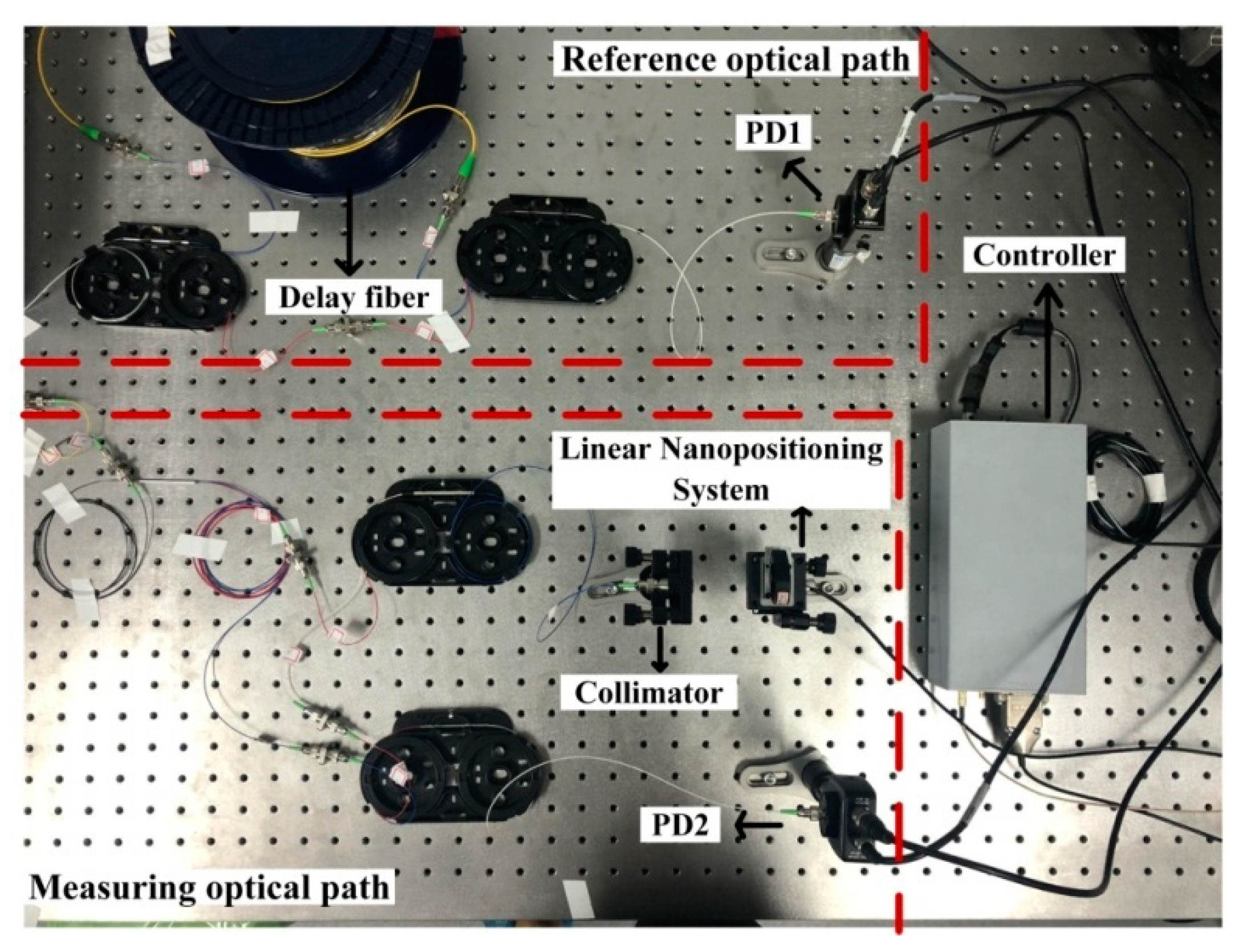
To verify the feasibility of the proposed method and deduce the applicable range of vibration compensation, the experiments were respectively carried out in the vibration environment and natural environment. First, the target was attached to a Precise PIHera Linear Nanopositioning System (Physik Instrumente GmbH, Karlsruhe, Germany) which was serving as a vibration source; the entire measurement system and target were placed on the same optical platform, and all experiments were carried out in a constant temperature and humidity environment, as shown in Figure 2. The Continuous Wave (CW) tunable laser (Lunainc, Blacksburg, VA, USA) was used as a sweeping source, and it had a tuning range of 1515–1565 nm and the tuning speed of 1–2000 nm/s. The output of the tunable laser was divided into two parts. One passed through the reference optical path, and its beat signal was used to remove the influence of nonlinear tuning; the delay fiber length which was calibrated by the gas absorption cell [1] certified by the National Institute of Standards and Technology (NIST) was 55.05m. Since the fiber length variation caused by temperature variation was very small, the influence of fiber length variation on measurement accuracy was negligible. The other passed through the measuring optical path, and its beat signal contained the wanted distance information. Then, the beat signals of the reference optical path and the measuring optical path were respectively detected by photodetector 1 (PD1) and photodetector 2 (PD2), of which both were Thorlabs PDA10CS-EC detectors. After that, all the PD signals were simultaneously sampled and recorded by an oscilloscope (Teledyne LeCroY, New York, NY, USA).
According to Equation (8), the frequency change of the beat signal in a single scanning period was given by:
Δ f = 4 v α 0 c ( T m 2 τ ) = v B c ( 4 16 R c T m ) .
In order to make the frequency change of the beat signal in a single scanning period as small as possible, the laser scanning bandwidth had to be small, the target vibration velocity had to be low, and the scanning period had to be short. Considering that the measured spectral resolution was inversely proportional to the scanning bandwidth, the scanning bandwidth of the laser and the modulation speed were set to 1 nm (1550–1551 nm) and 100 nm/s, respectively.
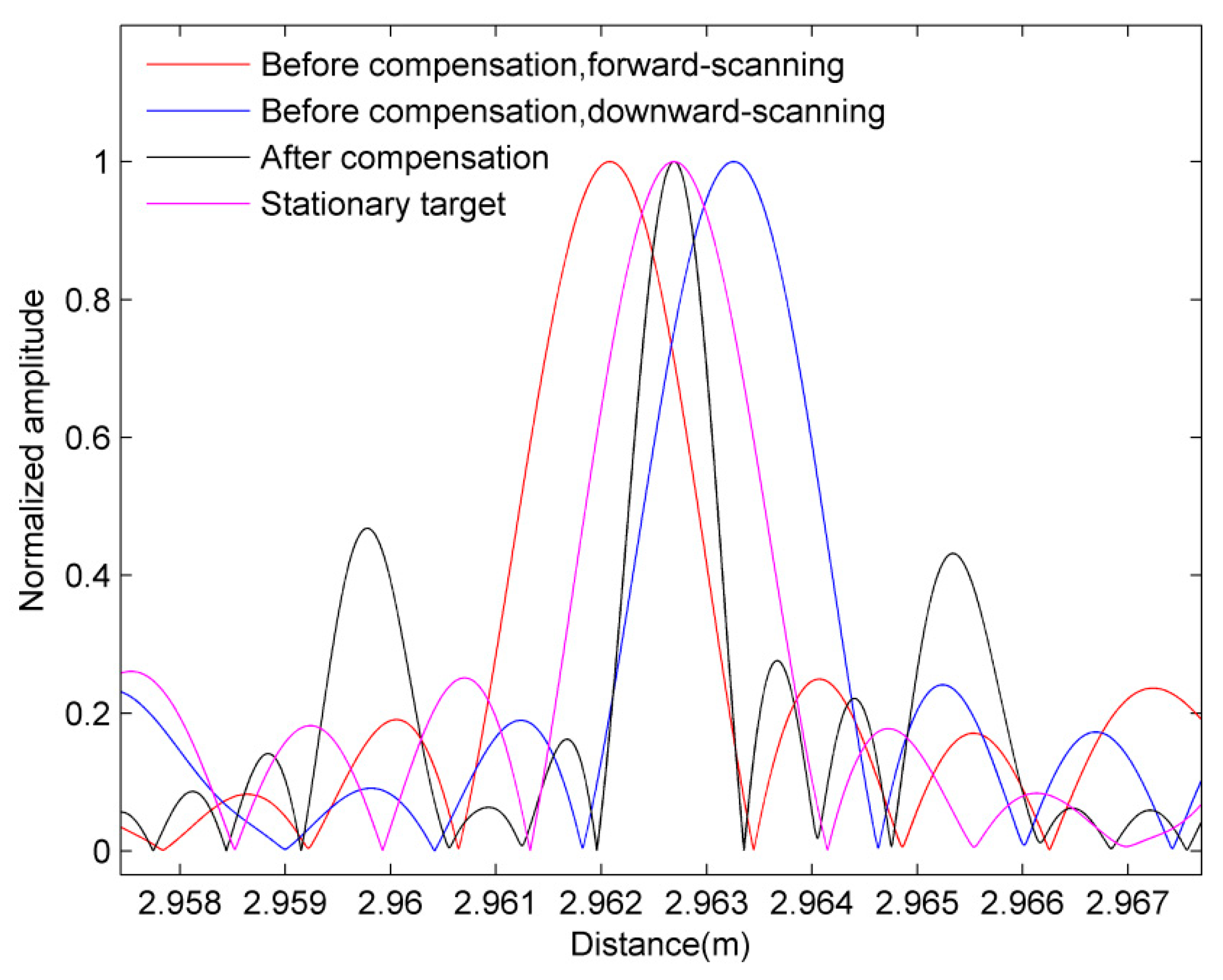
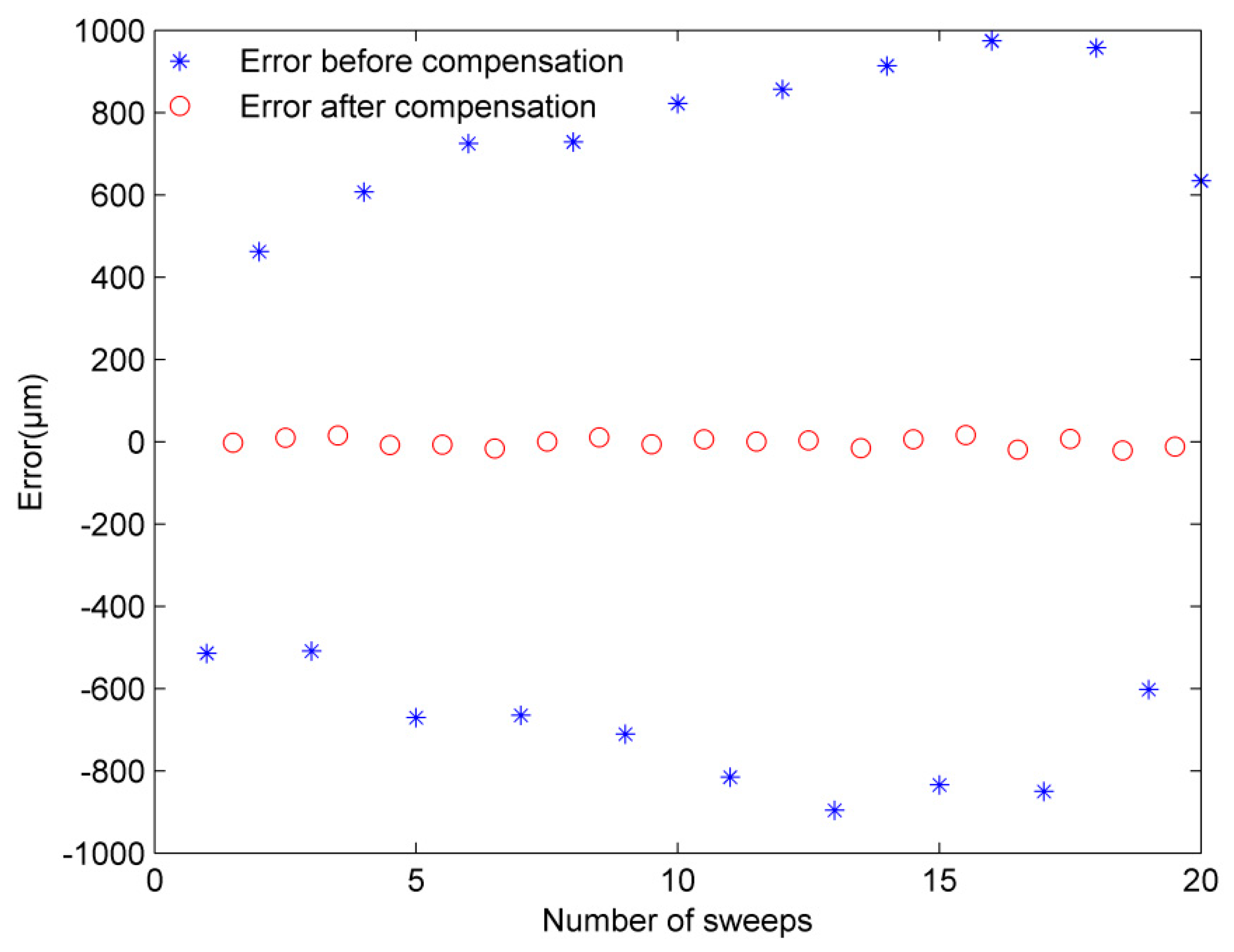
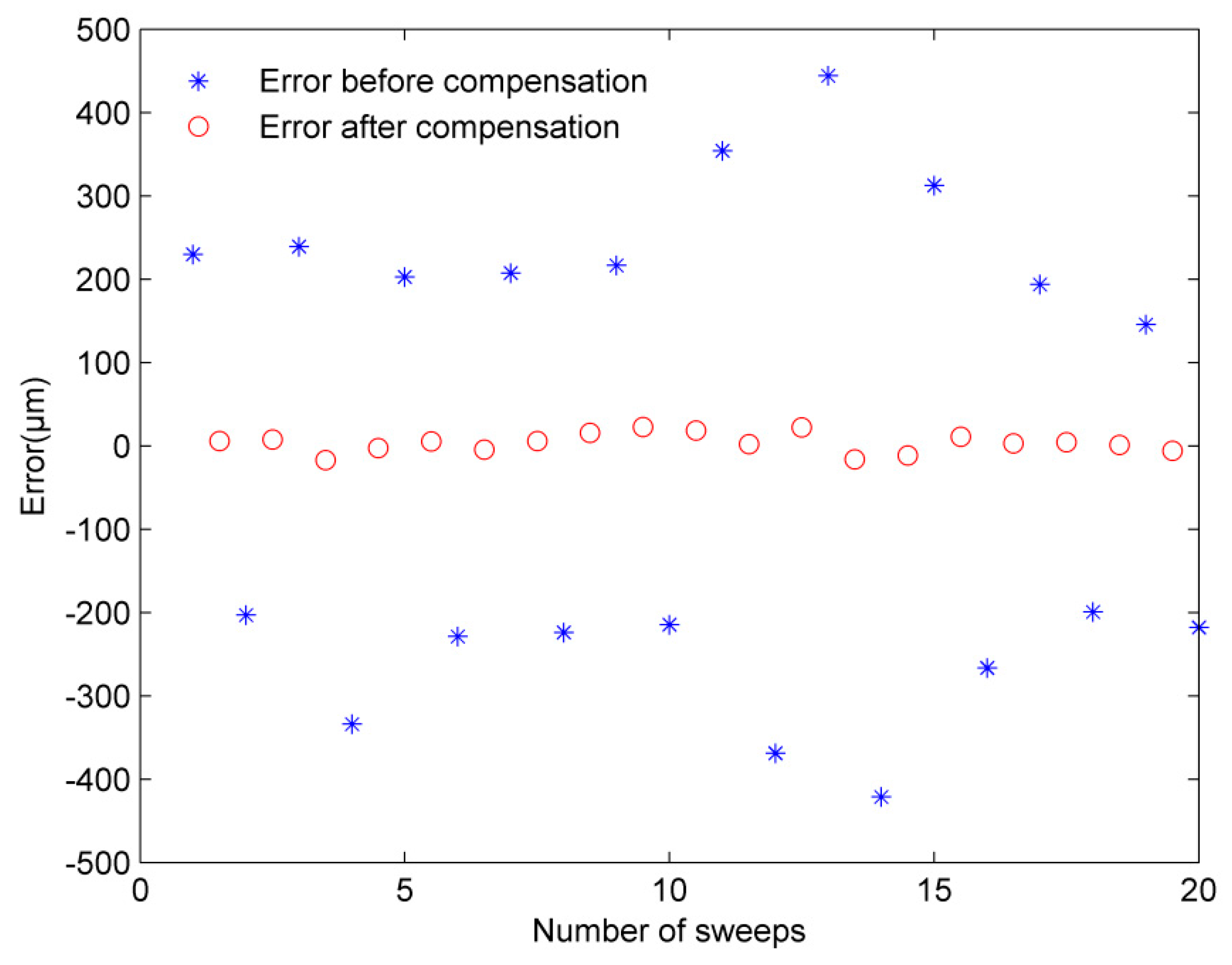
The experiments were carried out separately in the static and vibration environments. First, we repeated for 20 times the measurement for the stationary target, and then the target was subjected to a sinusoidal vibration with the amplitude of 10 μm at the frequency of 1 Hz. For the purpose of processing convenience, the amplitude of the beat signal was normalized. The obtained distance spectrum is shown in Figure 3, where the purple line denotes the CZT of the measurement beat signal for the stationary target (the distance value was calculated to be 2.962702 m), the red and blue lines denote the CZTs of the measurement beat signals of two adjacent scanning periods when the target vibrated (the distance values were calculated to be 2.962155 and 2.963275 m, respectively), and theblackline denotes the CZT of the new signal after the vibration compensation (the distance value was calculated to be 2.962710 m). It should be noted that the ranging errors before the vibration compensation were 547 and 573 μm, i.e., they were about 28 times larger than the actual vibration range of the target. After the vibration compensation, the ranging error was reduced to 8 μm, and the spectral resolution was cut down by half. The distance error before and after the vibration compensation is shown in Figure 4. After 20 repeated measurements, the standard deviation was reduced from 775 to 12 μm by using the proposed method.
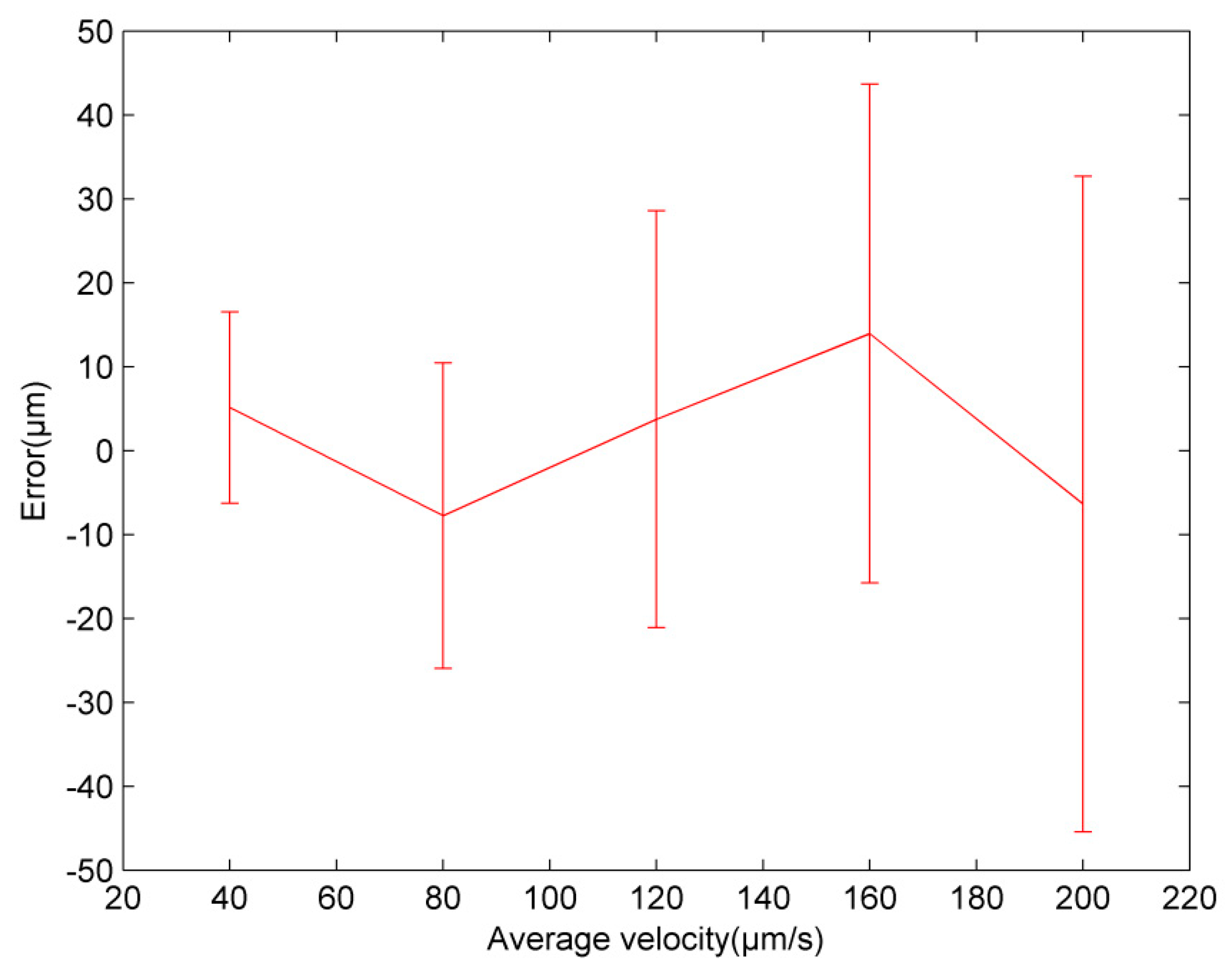
Subsequently, the target was subjected to a sinusoidal vibration with different amplitudes (vibration amplitude was 10, 20, 30, 40, and 50 μm, respectively, and the vibration frequency was 1 Hz). In other words, the average vibration velocity changed. The measurement was repeated 20 times before each change of the vibration amplitude. The distance value after the vibration compensation was compared with the corresponding average value of the 20 measurements to obtain the ranging error. As shown in Figure 5, the standard deviation gradually increased as the vibration velocity increased. At the average vibration velocity of 200 μm/s, the standard deviation obtained by the proposed method was 39 μm.
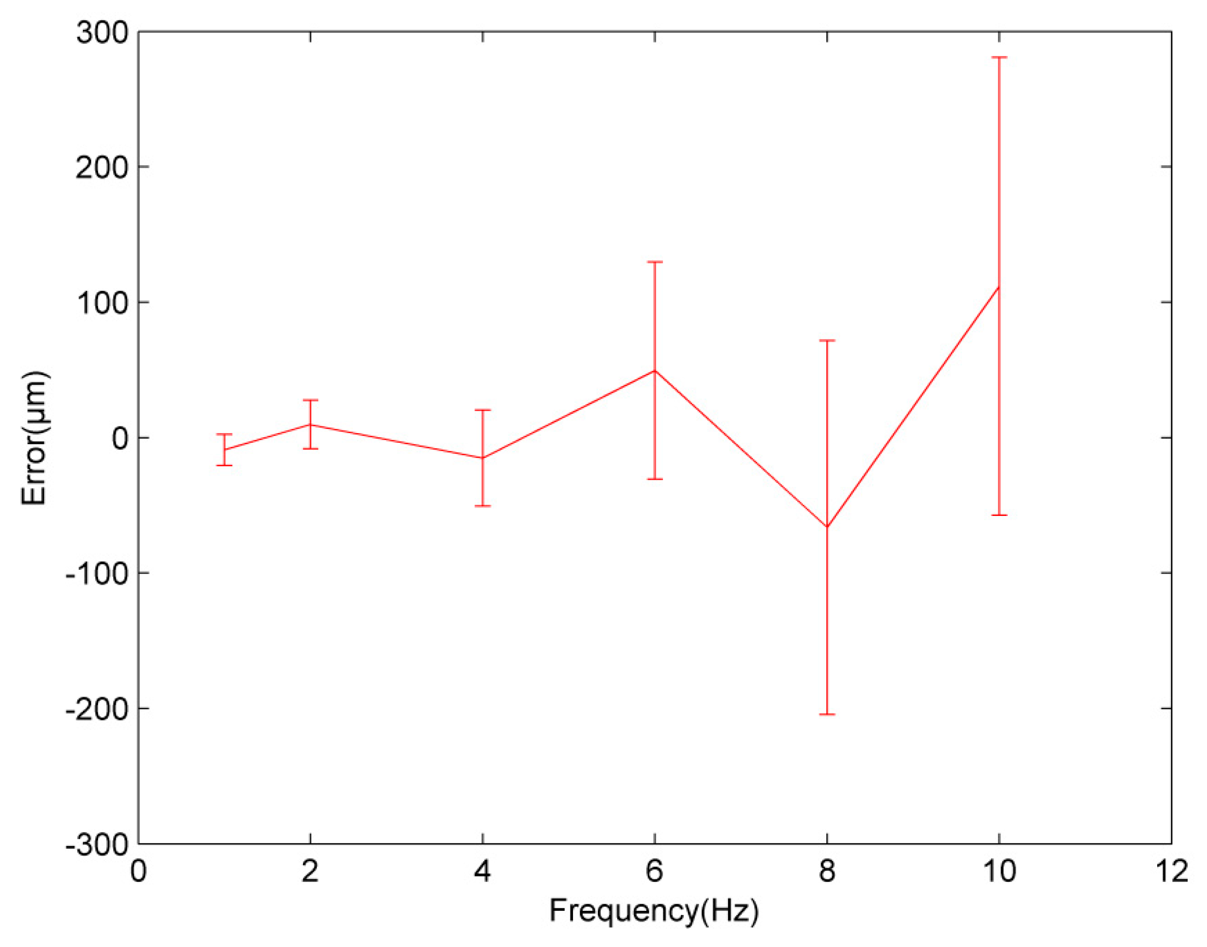
Finally, to obtain the applicable frequency range of vibration compensation, the target was sinusoidally vibrated at different vibration frequencies (vibration frequency was 1, 2, 4, 6, 8, and 10 Hz, respectively, and the vibration amplitude was 10 μm). The same method was used to obtain the ranging error, and 20 measurements were carried out at each vibration frequency. The results are shown in Figure 6, where it can be seen that vibration compensation had a significant effect when the vibration frequency was lower than 6 Hz. Nevertheless, at the vibration frequency higher than 6 Hz, both the measurement error and the standard deviation began to increase rapidly.

3.2. Vibration in Natural Environment

When the target and the measurement system were placed on the same platform, there was a little effect of vibration on a distance value. On the other hand, when the target and collimation lens were placed on two optical platforms having different heights, as shown in Figure 7, the effect of vibration in the natural environment was not negligible. Other experimental facilities and parameters are the same as previous experiments. The measurement results are shown in Figure 8. Obviously, the tiny displacement of the target was magnified, which resulted in a reduction in the ranging accuracy. For 20 repeated measurements, after the vibration compensation, the standard deviation was 11 μm, which was a much better result than that without the vibration compensation; namely, the standard deviation before vibration compensation was 289 μm.

4. Analysis and Discussion

In this paper, the vibration compensation is studied from two aspects, vibration velocity and vibration frequency. In the experiments, the frequency modulation term and the Doppler shift term were first introduced into the beat signal due to the tiny movement of the target, as explained in Section 2, and they were proportional to the target vibration velocity. In Figure 3, it can be seen that the distance spectrum deviated greatly compared with that of the stationary target due to the Doppler effect. In addition, the distance spectra of two adjacent scanning periods moved in opposite directions because of the opposite scanning directions. However, the influence of the frequency modulation term is not obvious in Figure 3 because of a low target vibration velocity and a short scanning period. With the acceleration of the target vibration velocity, the offset of the distance spectrum became larger, and the distance spectrum broadened, resulting in a decrease in vibration compensation, as shown in Figure 5. Consequently, it can be concluded that the target vibration velocity should be as small as possible and satisfy fd << α0τ. In our experiments, the laser scanning speed was 100 nm/s, the distance value was 2.9627 m, and the center wavelength of the output laser was 1550 nm. In the calculation, α0τ = 100 fd was used, and the vibration velocity was calculated to be 1.9 mm/s.
According to the presented results, it is obvious that the effect of vibration compensation was also related to the target vibration frequency. Figure 6 shows that the measurement standard deviation and measurement error began to increase significantly when the target vibration frequency was higher than 6 Hz. This phenomenon can be explained by two reasons. Firstly, the target velocity direction could change in a single scanning period with the change in the vibration frequency, which was inconsistent with our previous assumptions, resulting in a decrease in the measurement accuracy. Secondly, the target vibration velocity was also increasing, resulting in the broadening of the distance spectrum and the increase in the measurement error. Therefore, when the laser scanning frequency was 100 Hz, the effect of vibration compensation was better for the target with a lower vibration velocity and at the vibration frequency lower than 6 Hz.
Furthermore, we found that when the target and measurement system were placed on different platforms, the vibration became the main factor affecting the measurement result due to the inconsistent vibration frequencies of the two platforms (the influence of dispersion was very small because the distance to be measured and the scanning bandwidth were both small). After the vibration compensation, the standard deviation was reduced from 289 to 11 μm, which proved the feasibility of the proposed method in the practical application.

5. Conclusions

The FSI-based absolute ranging system is very sensitive even to a tiny target’s movement. To improve the ranging accuracy in practical applications, the vibration influence on the FSI-based absolute ranging system is profoundly analyzed. Then, from the point of view of system instrumentation and practicability, we propose to use a tunable laser to generate a triangular-wave frequency-modulated signal, and then to process the beat signals of two adjacent scanning periods to produce a signal which is immune to vibration. The proposed method was evaluated by the experiments in the vibration environment and natural environment, and the experimental results showed that the distance spectrum of the beat signal was offset and broadened when the target vibrated. Moreover, even tiny vibration displacements were magnified causing the error in the distance value. When the target was subjected to a sinusoidal vibration with the amplitude of 10 μm at the frequency of 1 Hz, the standard deviation before and after the vibration compensation was 775 and 12 μm, respectively. Besides, in a natural environment, after the vibration compensation, the standard deviation of 11 μm was obtained, which further proved the effectiveness of the proposed method. To summarize, when the laser scanning bandwidth was 1 nm, and the scanning frequency was 100 Hz, the vibration compensation effect was better for the target with a lower vibration velocity and at the vibration frequency lower than 6 Hz.

Author Contributions

Methodology and Writing the Paper, Y.-T.L.; Analysis and Investigation, F.-M.Z.; Experiments, Y.-T.L., X.-H.Q. and F.-M.Z.; Results Optimization, H.P. and C.-Z.S.

Funding

This research was funded by National Key Research and Development Program of China(2018YFF0212702) and Natural National Science Foundation of China—NSFC (51675380, 51775379).

Conflicts of Interest

The authors declare no conflict of interest.

References

  1. Pan, H.; Qu, X.H.; Zhang, F.M. Micron-precision measurement using a combined frequency-modulated continuous wave ladar autofocusing system at 60 meters standoff distance. Opt. Express. 2018, 26, 15186–15198. [Google Scholar] [CrossRef] [PubMed]
  2. Shi, G.; Wang, W. Single laser complex method to improve the resolution of FMCW laser ranging. J. Infrared Millim. Waves 2016, 35, 363–367. [Google Scholar]
  3. Jia, X.Y.; Liu, Z.G.; Deng, Z.W.; Deng, W.; Wang, Z.Y.; Zhen, Z.L. Dynamic absolute distance measurement by frequency sweeping interferometry based Doppler beat frequency tracking model. Opt. Commun. 2018, 430, 163–169. [Google Scholar] [CrossRef]
  4. Yang, H.J.; Deibel, J.; Nyberg, S.; Riles, K. High-precision absolute distance and vibration measurement with frequency scanned interferometry. Appl. Opt. 2005, 44, 3937–3944. [Google Scholar] [CrossRef] [PubMed]
  5. Pan, H.; Qu, X.H.; Shi, C.Z.; Li, Y.T.; Zhang, F.M. Precision evaluation method of measuring frequency modulated continuous wave laser distance. Acta Phys. Sin. 2018, 67, 090201. [Google Scholar]
  6. Liu, G.D.; Xu, X.K.; Liu, B.G.; Chen, F.D.; Hu, T.; Lu, C.; Gan, Y. A method of suppressing vibration for high precision broadband laser frequency scanning interferometry. Acta Phys. Sin. 2016, 65, 209501. [Google Scholar]
  7. Xu, Z.Y.; Tang, L.Z.; Zhang, H.X.; Pan, S.L. Simultaneous Real-Time Ranging and Velocimetry via a Dual-Sideband Chirped Lidar. IEEE Photon. Technol. Lett. 2017, 29, 2254–2257. [Google Scholar] [CrossRef]
  8. Wu, X.J.; Wei, H.Y.; Zhang, H.Y.; Ren, L.B.; Li, Y.; Zhang, J.T. Absolute distance measurement using frequency-sweeping heterodyne interferometer calibrated by an optical frequency comb. Appl. Opt. 2013, 52, 2042–2048. [Google Scholar] [CrossRef] [PubMed]
  9. Zhang, W.P.; Wei, H.Y.; Yang, H.L.; Wu, X.J.; Li, Y. Comb-referenced frequency-sweeping interferometry for precisely measuring large stepped structures. Appl. Opt. 2018, 57, 1247–1253. [Google Scholar] [CrossRef] [PubMed]
  10. Yang, L.J.; Wu, X.J.; Wei, H.Y.; Li, Y. Frequency comb calibrated frequency-sweeping interferometry for absolute group refractive index measurement of air. Appl. Opt. 2017, 56, 3109–3115. [Google Scholar] [CrossRef] [PubMed]
  11. Kakuma, S. Frequency-modulated continuous-wave laser radar using dual vertical-cavity surface-emitting laser diodes for real-time measurements of distance and radial velocity. Opt. Rev. 2017, 24, 39–46. [Google Scholar] [CrossRef]
  12. Tao, L.; Liu, Z.G.; Zhang, W.B.; Zhou, Y.L. Frequency-scanning interferometry for dynamic absolute distance measurement using Kalman filter. Opt. Lett. 2014, 39, 6997–7000. [Google Scholar] [CrossRef] [PubMed]
  13. Onori, D.; Scotti, F.; Scaffardi, M.; Bogoni, A.; Laghezza, F. Coherent Interferometric Dual-Frequency Laser Radar for Precise Range/Doppler Measurement. J. Lightw. Technol. 2016, 34, 4828–4834. [Google Scholar] [CrossRef]
  14. Kakuma, S.; Katase, Y. Frequency scanning interferometry immune to length drift using a pair of vertical-cavity surface-emitting laser diodes. Opt. Rev. 2012, 19, 376–380. [Google Scholar] [CrossRef]
  15. Schneider, R.; Thurmel, P.; Stockmann, M. Distance measurement of moving objects by frequency modulated laser radar. Opt. Eng. 2001, 40, 33–37. [Google Scholar] [CrossRef]
  16. Swinkels, B.L.; Bhattacharya, N.; Braat, J.J.M. Correcting movement errors in frequency-sweeping interferometry. Opt. Lett. 2005, 30, 2242–2244. [Google Scholar] [CrossRef] [PubMed]
  17. Bai, Y.; Ren, D.M.; Zhao, W.J.; Qu, Y.C.; Qian, L.M.; Chen, Z.L. Heterodyne Doppler velocity measurement of moving targets by mode-locked pulse laser. Opt. Express. 2012, 20, 764–768. [Google Scholar] [CrossRef] [PubMed]
  18. Lu, C.; Liu, G.D.; Liu, B.G.; Chen, F.D.; Gan, Y. Absolute distance measurement system with micron-grade measurement uncertainty and 24 m range using frequency scanning interferometry with compensation of environmental vibration. Opt. Express. 2016, 24, 30215–30224. [Google Scholar] [CrossRef] [PubMed]
  19. Martinez, J.J.; Campbell, M.A.; Warden, M.S.; Hughes, E.B.; Copner, N.J.; Lewis, A.J. Dual-Sweep Frequency Scanning Interferometry Using Four Wave Mixing. IEEE Photon. Technol. Lett. 2015, 27, 733–736. [Google Scholar] [CrossRef]
  20. Jia, X.Y.; Liu, Z.G.; Tao, L.; Deng, Z.W. Frequency-scanning interferometry using a time-varying Kalman filter for dynamic tracking measurements. Opt. Express. 2017, 25, 25782–25796. [Google Scholar] [CrossRef] [PubMed]
  21. Meng, X.S.; Zhang, F.M.; Qu, X.H. High precision and fast method for absolute distance measurement based on resampling technique used in FM continuous wave laser ranging. Acta Phys. Sin. 2015, 64, 2306010. [Google Scholar]
  22. Ahn, T.J.; Kim, D.Y. Analysis of nonlinear frequency sweep in high-speed tunable laser sources using a self-homodyne measurement and Hilbert transformation. Appl. Opt. 2007, 46, 2394–2400. [Google Scholar] [CrossRef] [PubMed]
  23. Shi, G.; Zhang, F.M.; Qu, X.H.; Meng, X.S. Absolute distance measurement by high resolution frequency modulated continuous wave laser. Acta Phys. Sin. 2014, 63, 184209. [Google Scholar]
  24. Zheng, J. Continued analysis of optical frequency-modulated continuous-wave interference. Appl. Opt. 2005, 44, 765–769. [Google Scholar] [CrossRef] [PubMed]
  25. Deng, Z.W.; Liu, Z.G.; Li, B.; Liu, Z. Precision improvement in frequency-scanning interferometry based on suppressing nonlinear optical frequency sweeping. Opt. Rev. 2015, 22, 724–730. [Google Scholar] [CrossRef]
Figure 1. Schematic diagram of the FSI-based absolute ranging system.
Applsci 09 00147 g001
Figure 2. The experimental setup.
Applsci 09 00147 g002
Figure 3. Distance spectrum before and after the vibration compensation at the frequency of 1 Hz and the amplitude of 10 μm.
Applsci 09 00147 g003
Figure 4. Distance error before and after the vibration compensation at the frequency of 1 Hz and the amplitude of 10 μm.
Applsci 09 00147 g004
Figure 5. Error and standard deviation at different average velocities (after the vibration compensation).
Applsci 09 00147 g005
Figure 6. Error and standard deviation at different vibration frequencies (after the vibration compensation).
Applsci 09 00147 g006
Figure 7. The target mirror and collimating lens placed on different platforms.
Applsci 09 00147 g007
Figure 8. Distance error before and after the vibration compensation in a natural environment.
Applsci 09 00147 g008