Frequency Difference Thermally and Electrically Tunable Dual-Frequency Nd:YAG/LiTaO3 Microchip Laser


Beijing Institute of Technology, School of Optics and Photonics, 5 South Zhongguancun Street, Beijing 100081, China
*
Authors to whom correspondence should be addressed.
Appl. Sci. 2019, 9(10), 1969; https://doi.org/10.3390/app9101969
Submission received: 13 March 2019
/
Revised: 1 May 2019
/
Accepted: 9 May 2019
/
Published: 14 May 2019
(This article belongs to the Special Issue Novel Advances in Optical Micro- and Nano-Cavities)
Abstract
:This study presents a dual-frequency microchip laser with a thermo-optically and electro-optically tuned frequency difference. The dual-frequency microchip cavity is formed by bonding a Lithium tantalite (LiTaO3, LTO) crystal chip and a neodymium-doped yttrium aluminum garnet (Nd:YAG) crystal chip. A single longitudinal mode is generated by the Nd:YAG crystal and split into two frequencies with perpendicular polarizations due to birefringent effect in the LTO chip. Furthermore, continuous beat frequency tuning at different scales is realized by adjusting the temperature and voltage applied to the LTO crystal. A maximum beat frequency of up to 27 GHz is obtained, and the frequency difference lock-in phenomenon is observed below the frequency difference of 405 MHz.
1. Introduction
Frequency difference tunable dual-frequency lasers have drawn a lot of attention in the last few years for their applications in the fields of absolute distance interferometry, Light Detection and Ranging (LIDAR) detection and terahertz wave generation [1,2,3]. In recent years, significant achievements have been made in the research of dual-frequency lasers, such as the intensity balance ratio, beat note stability and beat effect-based Q-switch regime [4,5,6]. These achievements have led to dual-frequency laser technology with a complete system and rich connotation. LIDAR with a tunable dual-frequency laser as the light source has a better performance, for that the range and accuracy of speed measurement can be greatly improved. If the beat frequency can be tuned according to a target’s speed, one can get the proper Doppler frequency shift which is more convenient for signal processing. If the beat frequency reaches several GHz or higher, the moving speed of m/s or even mm/s can be measured easier [7,8]. As well as in terms of distance measurement, with an ability to change the wavelength of the beat signal and realize high-resolution detection of targets at different distances [9,10]. Therefore, the tuning capability of frequency difference is an important property of the dual-frequency laser.
The principle of birefringence is a common method implemented to split a single-frequency into a dual-frequency. For example, using two quarter-wave plates, one can continuously tune the frequency difference from a few gigahertz to 150 GHz [11,12]. However, the inaccurate rotating of the quarter wave plate hampers its application under circumstances where high precision is required. Mechanical stress-induced birefringence can generate a several GHz beat frequency signal with good linear relation. However, the beat frequency is not stable enough and is susceptible to external forces. It is necessary to pay attention to the pressure to avoid crushing the crystal, which also limits the range of frequency difference adjustment with this method [5,13]. Changing the temperature of the birefringent crystal can change its refractive index, which can tune the frequency difference over a wide range from 0 to 60 GHz [14]. Using the electro-optical effect of the crystal, an external electric field can be applied to tune the frequency difference with a short response time [15,16]. However, to achieve the few gigahertz frequency difference tuning, usually an applied voltage of several thousand volts is required.
This paper presents a dual-frequency microchip laser with a frequency difference that can be tuned by varying the cooling temperature and voltage applied to the laser. With a wide gain bandwidth, the Nd:YAG microchip is used as the gain medium to realize broad-range tuning of the beat frequency. LTO, as the birefringent crystal, has good thermal stability and a large electro-optical coefficient, making it an ideal candidate for dual-frequency generation. The single-frequency generated by the Nd:YAG is split into two perpendicularly polarized components by the LTO crystal. Furthermore, their frequency difference is first large-scale adjusted by controlling the cooling temperature, then fine-scale adjusted by the variable voltage applied to the LTO crystal. Combined with temperature- and voltage-tuning methods, it can ensure broad-range and high-accuracy tuning of the frequency difference simultaneously.
2. Experimental Setup
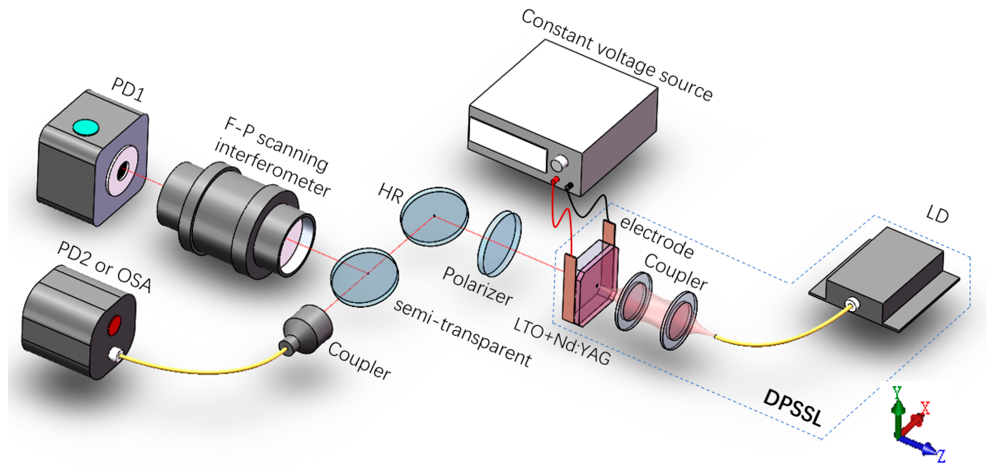
The schematic diagram of the dual-frequency microchip laser and its relevant measurement method are shown in Figure 1. The composite laser cavity consists of a 1% at doped Nd3+:YAG gain medium chip with a 0.4 mm thickness and an LTO electro-optic crystal with 1 mm thickness. The two chips both have transverse dimensions of 5 × 5 mm2, and are combined by the optical cement method. The surface of the Nd:YAG crystal is coated with a film that has high reflectivity (R > 99.7%) at 1064 nm and high transmissivity (T > 97%) at 808 nm, which serves as the end mirror of the cavity. The surface of LTO is coated with a film of high reflectivity (R = 99%) at 1064 nm, which serves as the output coupling mirror. An 808 nm diode laser coupled with an optical fiber (fiber core diameter is 105 , NA = 0.22) is used as the pump source to match one of the Nd3+ ion absorption peaks. The pump beam is focused into the Nd:YAG crystal with a spot size of about 100 µm in diameter. The dual-frequency beam with orthogonal polarizations can be generated by virtue of the birefringence of LTO. A thermoelectric cooler (TEC) is used to control the temperature of the microchip laser. The lateral surface of LTO is coated with gold film, on which two electrodes are glued with conductive adhesive to apply a transverse electric field by a constant voltage source. The dual-frequency beam passes through the polarizer to generate a beat note. A high reflection (HR) mirror for the laser beam can also split pump light. The longitudinal modes could be measured by a Fabry-Perot (F-P) scanning interferometer. And the optical spectrum or beat frequency are measured by an optical spectrum analyzer or a radio frequency (RF) analyzer.
3. Theoretical Analysis
In the microchip cavity, the stable oscillating laser satisfies the standing wave condition and has an optical frequency of:
where is the velocity of light, is the optical path of the cavity, and is a natural number. The longitudinal mode interval is . The optical path of the cavity consists of and The refractive index of Nd:YAG is 1.82, and for LTO, the mean value is 2.14. Then we can get a longitudinal mode interval of 52.3 GHz. As the total gain bandwidth of Nd:YAG is estimated to be 120 GHz, this means that the cavity can generate two or three longitudinal modes at most. While, by applying relatively low pump power (about within 1.6 times of the threshold power) in the experiment, single longitudinal mode output could be obtained.
Since the LTO in our experiment is a-cut, the single frequency can be split into two frequencies with perpendicularly linear polarizations under its natural birefringence (the ordinary light polarized along the x axis, and the extraordinary light polarized along the y axis). The frequency difference of the two polarized light can be derived by the equation below:
where = 2.1403, are the refractive indices of the ordinary and extraordinary light, respectively.
As the birefractive indexes of the LTO crystal is affected by temperature, the frequency difference has a correlationship with the cooling temperature of the microchip. The variation of the frequency difference with the cooling temperature is determined by the equation below [17]:
where is the expansion coefficient of LTO crystal in z direction. The value of parameters used in this paper are , , [17].
And as an electro-optic crystal, the birefractive indexes can also be tuned by electric filed. In the experiment, a transverse electric field is applied to the LTO crystal along the x axis. Due to the electro-optical effect, the refractive indexes of the LTO crystal along x and y axes are changed, and the changed value is proportional to the electric field strength and the electro-optic coefficient of LTO crystal.
Here , and is the applied voltage. The relationship between the voltage, the frequency difference of the ordinary light, and the extraordinary light is:
Equations (3) and (5) give the theoretical relationships of Δυ with cooling temperature and applied voltage. For prediction of experiments results the slope tuning of the frequency difference versus temperature and voltage are calculated:
4. Experimental Results and Discussion
In our experiment, the lasing threshold of the microchip laser was found at around 900 mW, at room temperature. At first, it was a single frequency output with x polarization. And when the pump power was increased, the y polarization TEM00 mode was generated, due to a relatively low spectral gain for the y polarization mode. If the pump power increased to exceed 1.5 W, the neighboring longitudinal mode was generated. In the experiment, we obtained a dual-frequency laser output of about 34 mW at a pump power of 1.5 W.
4.1. Thermally Tunable Frequency Difference
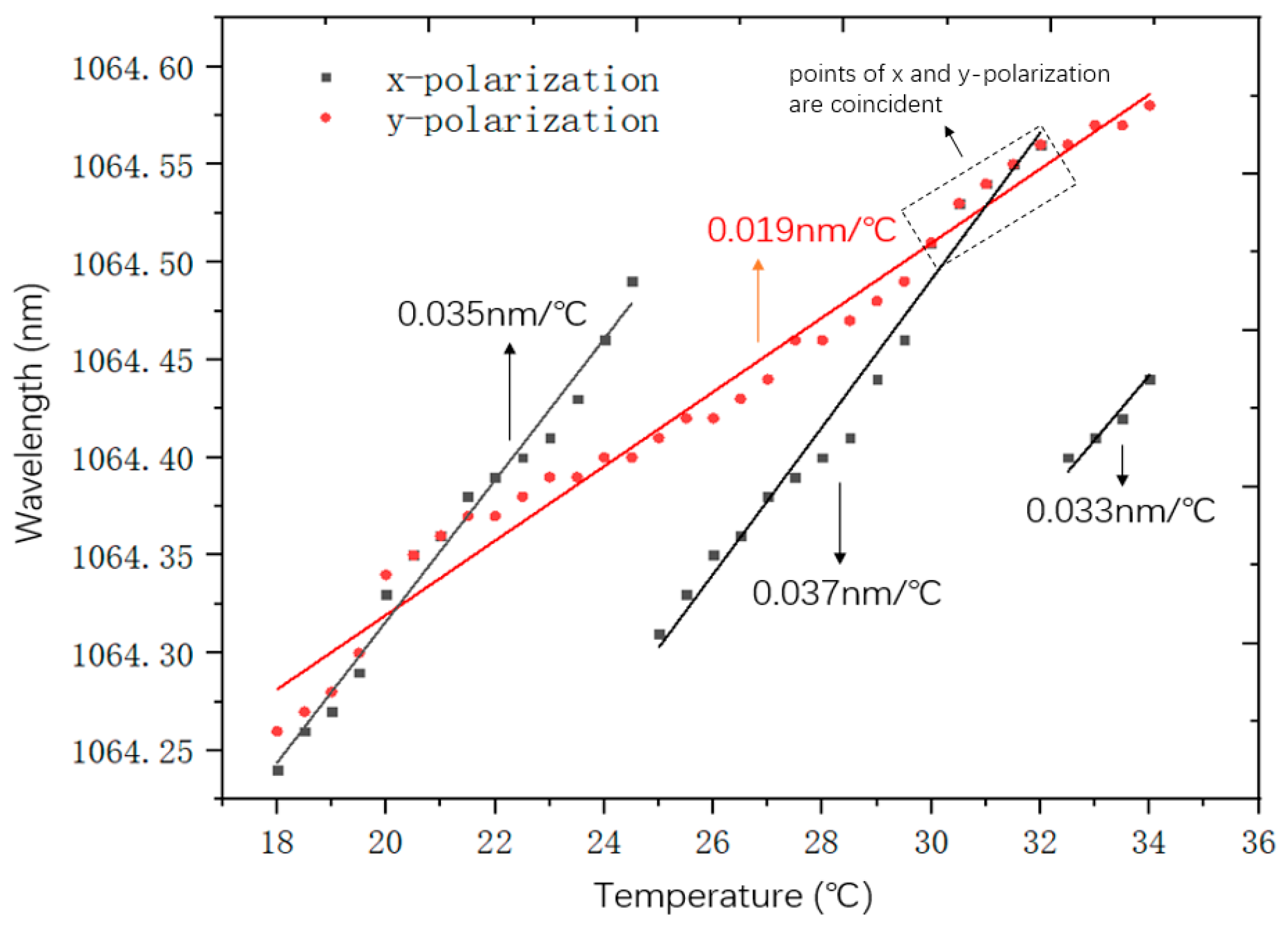
To roughly measure the frequency differences in a large range (about tens of GHz) by tuning cooling temperature, a LSA IR-L optical spectrum analyzer with 0.02 nm resolution was used. The cooling temperature was continuously increased from 18 °C to 34 °C with a step interval of 0.5 °C. The measurement results are shown in Figure 2.
The x and y polarization correspond to the black and the red curves respectively. By fitting the data points, it can be seen that the laser wavelengths of the two polarizations vary linearly with the temperature increasing. It can be seen that, for y polarized wave, the wavelength curve is monotonic increasing from 1064.26 nm to 1064.58 nm. While, for the x polarized wave curve, there are two saltus steps at the temperature around 25 °C and 32 °C. This is because of the longitudinal mode is hopping between neighbor longitudinal modes. It’s affected by the relative positions of the gain curve and the cavity longitudinal modes. When the longitudinal mode’s optical frequency shifts away from the center of the gain curve, its gain coefficient will drop. Frequency of the neighboring longitudinal mode will move closer to the center of the gain curve and obtain a larger gain coefficient. Due to mode competition, when the net gain of the latter is stronger than that of the former, the former will be extinguished. The mode hopping occurred at 24.5 °C, the wavelength changed from 1064.49 nm to 1064.31 nm, coming with an approximate 54 GHz frequency difference change, and the second one occurred at 31.5 °C, the wavelength changed from 1064.56 nm to 1064.39 nm, with a 51 GHz frequency difference change, approximately. They were both very close to the longitudinal mode interval of 52.3 GHz. While, it’s interesting that there was no mode hoping for the y polarized wave in such a large frequency variation range, further investigation on this problem is needed in later works.
When the cooling temperature was between 18 °C and 24.5 °C, the wavelengths of both the ordinary and the extraordinary beam continuously changed with temperature, and no mode hopping occurred. In this temperature range, we used an F-P scanning interferometer to measure the frequency differences more precisely. the F-P scanning interferometer continuously changes the transmission frequency by scanning voltage, ensuring that all frequencies could be transmitted and detected by its photodetector at the back end. Using the F-P scanning interferometer, the number of frequencies and frequency interval of the laser output can be measured. The measurement results are shown in Figure 3a. The results are fitted to obtain a good linear relationship between the frequency difference and the cooling temperature, with an average tuning slope of 4.4 GHz/°C. It could be seen that there was a reverse between 20.5 °C and 21 °C during the temperature’s variation. At 18 °C to 20.5 °C, it was seen , and at 21 °C to 24.5 °C, it changed to . The tuning slopes in the two temperature ranges were −4.45 GHz/°C and 4.62 GHz/°C, respectively. The average inaccuracy of the frequency difference for each point was about ± 50 MHz, due to the ± 0.01 °C accuracy of the temperature controller we used. The maximum frequency difference reached 27 GHz at 24.5 °C.
In the experiment, we observed that as the frequency of the two orthogonally polarized beams got quite close, one of them was extinguished, resulting in a single polarization output. This is a lock-in phenomenon of the two frequencies [18]. It is a ubiquitous phenomenon the orthogonally polarized dual-frequency lasers. Previous research on this phenomenon was focused on He–Ne lasers. The He–Ne dual-frequency laser based on the birefringent effect has a frequency difference lock-in of about 40 MHz [19]. As far as we know, there is no report on the frequency of the lock-in phenomenon in solid-state dual-frequency lasers, while a quite low beat frequency can be achieved [20]. Considering the c-cut condition of the LTO crystal, the light oscillates parallel to the optical axis in the resonant cavity, and the frequency does not split due to the same refractive index for the a and b axes of LTO. If voltage or pressure is applied to change the direction and refractive index of the crystal’s optical axis, the frequency difference will increase from a small value without a significant frequency difference lock-in effect [15]. In our experiment, the electro-optic crystal was a-cut, and the optical axis was perpendicular to the direction of light propagation. Due to natural birefringence, the frequency difference between two orthogonally polarized beams split by the same longitudinal mode is large at room temperature (24 °C), with a magnitude of more than 10 GHz. The minimum value of the frequency difference was measured during the continuous changing of the temperature. It can be seen from the measurement results in Figure 3a that the frequency difference continuously decreased as the temperature decreased, and the two frequencies should thus coincide between 20.5 °C and 21 °C. Considering that the measurement accuracy is limited with an optical spectrum analyzer, the minimum value of the frequency difference cannot be accurately detected. Then, we switch to a RF spectrum analyzer with an InGaAs photon detector, its wavelength response range was 950–1630 nm and the bandwidth was 3.5 GHz. At 21.3 °C, a frequency difference of 3.0 GHz was detected, and the temperature is continuously reduced. The curve of the frequency difference showed a process of folding back in the 20.6–20.8 °C range, as shown in Figure 3b. This indicates that the frequency difference had passed through the minimum value of about 405 MHz. The results show that when the frequency difference dropped to 405 MHz, within a small range of temperature regulation (0.1 °C), the beat frequency signal disappeared. When the frequency difference was close to 405 MHz, by keeping the temperature constant and applying a voltage to change the frequency difference continuously, it was found that the beat frequency signal also disappeared below 405 MHz.
4.2. Electrically Tunable Frequency Difference
In order to achieve more precise tuning of the beat frequency, a high direct-voltage was applied to the electrode on the LTO crystal. The transverse electric field changed the refractive indexes of b and c axes of LTO, and realized the tuning of the frequency difference. The relationship between the voltage and the frequency difference depends on Equation (5) in Section 3. With no voltage applied, a frequency difference of 0.7 GHz was obtained at 20.8 °C, as shown in Figure 3b. When the voltage was applied, we could obtain the beat frequency versus the voltage, as shown in Figure 4. The results were detected by the photodiode and measured by a RF spectrum analyzer. Due to the influence of controlling temperature accuracy, the frequency difference had the same fluctuation value as that in Figure 3. Here, we selected the median value of the float as the data point.
The measurement results showed that the curve of frequency difference vs. voltage changes linearly with a tuning slope of 1.23 MHz/V. Considering that the accuracy of the applied voltage was 1.0 V, it was more sensitive compared with controlling the temperature. On the other hand, the applied voltage not only tunes the frequency difference more accurately and quickly than the temperature, but also facilitates the stabilization of the frequency difference with a phase-locked loop [21]. Compared with the electro-optical coefficient = 8.6 pm/V, = 30.8 pm/V of LiNbO3, the difference between the electro-optic coefficients pm/V and pm/V of LiTaO3 is larger. It can be seen from Equation (5) that this is more favorable for obtaining a wide range of tuning of the frequency difference. Theoretically, a similar maximum frequency difference to the temperature tuning can be achieved by increasing the applied voltage. However, due to the low sensitivity, if we want to achieve a frequency difference of up to about 20 GHz, an extremely high voltage of 16 kV is required. Compared with the thermal tuning method, its cost is high and the processing difficulty of insulating the laser cavity is increased. So, large-scale thermal tuning of the frequency difference is needed.
5. Conclusions
A beat frequency tunable dual-frequency microchip laser is realized based on the thermo-optical and electro-optical effects of a LTO crystal. Through theoretical analysis, it is found that the temperature and voltage can be adjusted to tune the frequency difference at different scales. By combining the thermal and electrical tuning methods in an experiment, we demonstrated it can ensure broad-range and high-accuracy tuning of the frequency difference simultaneously. The frequency difference can be tuned by the temperature and voltage with a sensitivity of 4.5 GHz/°C and 1.23 MHz/V, respectively. The maximum frequency difference achieved is about 27 GHz, and the minimum tunable frequency difference obtained is about 405 MHz due to the lock-in effect of two frequencies.
Author Contributions
Conceptualization, C.Z., Z.Z. and K.G.; methodology, Z.Z. and K.G.; software, K.G. and Y.X.; validation, Z.Z., Y.X. and K.G.; formal analysis, K.G.; investigation, Z.Z., H.Z. and K.G.; resources, Z.Z., H.Z. and C.Z.; data curation, K.G.; writing—original draft preparation, K.G.; writing—review and editing, Z.Z. and K.G.; visualization, K.G.; supervision, Z.Z., H.Z. and C.Z.; project administration, Z.Z.; funding acquisition, Z.Z.
Funding
This research is funded by the National Natural Science Foundation of China, grant number 61805013.
Conflicts of Interest
The authors declare no conflict of interest.
References
- Pillet, G.; Morvan, L.; Ménager, L.; Garcia, A.; Babiel, S.; Stöhr, A. Dual-Frequency Laser Phase Locked at 100 GHz. J. Lightw. Technol. 2014, 32, 3824–3830. [Google Scholar] [CrossRef]
- Paquet, R.; Le Gratiet, L.; Sellahi, M.; Chomet, B.; Beaudoin, G.; Sagnes, I.; Garnache, A.; Blin, S.; Myara, M. Coherent continuous-wave dual-frequency high-Q external-cavity semiconductor laser for GHz–THz applications. Opt. Lett. 2016, 41, 3751–3754. [Google Scholar] [CrossRef] [PubMed]
- Brunel, M.; Lai, N.D.; Vallet, M.; Le Floch, A.; Bretenaker, F.; Morvan, L.; Dolfi, D.; Huignard, J.P.; Blanc, S.; Merlet, T. Generation of tunable high-purity microwave and terahertz signals by two-frequency solid state lasers. Proc. SPIE 2004, 5466. [Google Scholar] [CrossRef]
- Hu, M.; Wei, M.; Zeng, R.; Li, Q.; Lu, Y.; Wei, Y.; Zhang, Y. Microchip dual-frequency laser with well-balanced intensity utilizing temperature control. Opt. Express 2016, 24, 23383–23389. [Google Scholar] [CrossRef] [PubMed]
- Li, J.; Niu, Y.; Niu, H. Frequency difference stabilization in dual-frequency laser by stress-induced birefringence closed-loop control. Appl. Opt. 2016, 55, 4357–4361. [Google Scholar] [CrossRef] [PubMed]
- Zhang, Z.; Gui, K.; Zhao, C.; Zhang, H.; Chen, S.; Zhou, G. Self-Q-switch regime based on a beat effect with a dual-frequency microchip laser. Phys. Rev. A 2018, 98, 033831. [Google Scholar] [CrossRef]
- Yang, H.; Brunel, M.; Zhang, H.; Vallet, M.; Zhao, C.; Yang, S. RF Up-Conversion and Waveform Generation Using a Frequency-Shifting Amplifying Fiber Loop, Application to Doppler Velocimetry. IEEE Photonics J. 2017, 9, 1–9. [Google Scholar] [CrossRef]
- Chen, J.; Zhu, H.; Guo, D.; Hao, H.; Xia, W.; Wang, M. Self-mixing birefringent dual-frequency laser Doppler velocimeter. Opt. Express 2017, 25, 560–572. [Google Scholar] [CrossRef] [PubMed]
- Onori, D.; Scotti, F.; Laghezza, F.; Scaffardi, M.; Bogoni, A. Coherent laser radar with dual-frequency Doppler estimation and interferometric range detection. In Proceedings of the Radar Conference (RadarConf), Philadelphia, PA, USA, 2–6 May 2016. [Google Scholar]
- Zheng, X.; Zhao, C.; Zhang, H.; Zheng, Z.; Yang, H. Coherent dual-frequency lidar system design for distance and speed measurements. In Proceedings of the 2017 International Conference on Optical Instruments and Technology: Advanced Laser Technology and Applications, Beijing, China, 28–30 October 2017. [Google Scholar]
- Mckay, A.; Dawes, J.M. Tunable Terahertz Signals Using a Helicoidally Polarized Ceramic Microchip Laser. IEEE Photonics Technol. Lett. 2009, 21, 480–482. [Google Scholar] [CrossRef]
- Romanelli, M.; Wang, L.; Brunel, M.; Vallet, M. Measuring the universal synchronization properties of driven oscillators across a Hopf instability. Opt. Express 2014, 22, 7364–7373. [Google Scholar] [CrossRef] [PubMed] [Green Version]
- Huang, C.N.; Li, Y.; Guo, H.; Zhu, J.; Zhang, S. Novel tunable dual-frequency laser with large frequency difference. Chin. J. Lasers 2002, 11, 229–231. [Google Scholar] [CrossRef]
- Brunel, M.; Amon, A.; Vallet, M. Dual-polarization microchip lasers at 1.53 um. Opt. Lett. 2005, 30, 2418–2420. [Google Scholar] [CrossRef] [PubMed]
- Qiao, Y.; Zheng, S.; Chi, H.; Jin, X.; Zhang, X. Electro-optically tunable microwave source based on composite-cavity microchip laser. Opt. Express 2012, 20, 29090–29095. [Google Scholar] [CrossRef] [PubMed]
- Rolland, A.; Brunel, M.; Loas, G.; Frein, L.; Vallet, M.; Alouini, M. Beat note stabilization of a 10-60 GHz dual-polarization microlaser through optical down conversion. Opt. Express 2011, 19, 4399–4404. [Google Scholar] [CrossRef] [PubMed]
- Rolland, A.; Frein, L.; Vallet, M.; Brunel, M.; Bondu, F.; Merlet, T. 40-GHz Photonic Synthesizer Using a Dual-Polarization Microlaser. IEEE Photonics Technol. Lett. 2010, 22, 1738–1740. [Google Scholar] [CrossRef]
- Yang, S.; Zhang, S. The frequency split phenomenon in a He-Ne laser with a rotational quartz plate in its cavity. Opt. Commun. 1988, 68, 55–57. [Google Scholar] [CrossRef]
- Jin, Y.Y.; Zhang, S.L.; Li, Y.; Guo, J.-H.; Li, J.-Q. Zeeman-birefringence He-Ne dual frequency laser. Chin. Phys. Lett. 2001, 18, 533–536. [Google Scholar] [CrossRef]
- Gudelev, V.G.; Mashko, V.V.; Nikeenko, N.K.; Ryabtsev, G.I.; Stalmashonak, A.B.; Teplyashin, L.L. Diode-pumped cw tunable two-frequency YAG:Nd3+ laser with coupled resonators. Appl. Phys. B 2003, 76, 249–252. [Google Scholar] [CrossRef]
- Rolland, A.; Loas, G.; Brunel, M.; Frein, L.; Vallet, M.; Alouini, M. Non-linear optoelectronic phase-locked loop for stabilization of opto-millimeter waves: Towards a narrow linewidth tunable THz source. Opt. Express 2011, 19, 17944–17950. [Google Scholar] [CrossRef] [PubMed]
Figure 1.
Schematic diagram of the experimental setup. LD, laser diode; HR, high-reflective mirror (@1064nm); PD, photoelectric detector; OSA, optical spectrum analyzer; DPSSL, diode-pumped solid-state laser.
Figure 1.
Schematic diagram of the experimental setup. LD, laser diode; HR, high-reflective mirror (@1064nm); PD, photoelectric detector; OSA, optical spectrum analyzer; DPSSL, diode-pumped solid-state laser.

Figure 2.
Variations of the wavelengths of the dual-frequency components with temperature increasing from 18 °C to 34 °C. The points of x- and y-polarization are approximately overlapped between 30 °C and 32 °C.
Figure 2.
Variations of the wavelengths of the dual-frequency components with temperature increasing from 18 °C to 34 °C. The points of x- and y-polarization are approximately overlapped between 30 °C and 32 °C.

Figure 3.
The relationship between the frequency difference and temperature of 18 °C–24.5 °C (a) and 20.4 °C–21.3 °C (b). Data was measured by an F-P scanning interferometer. The minimum value of the frequency difference (in the insert of (b)) at 20.7 °C was measured by a fiber input photon detector.

Figure 4.
The relationship between the frequency difference and voltage when the temperature is constant.
Figure 4.
The relationship between the frequency difference and voltage when the temperature is constant.

© 2019 by the authors. Licensee MDPI, Basel, Switzerland. This article is an open access article distributed under the terms and conditions of the Creative Commons Attribution (CC BY) license (http://creativecommons.org/licenses/by/4.0/).
Share and Cite
MDPI and ACS Style
Gui, K.; Zhang, Z.; Xing, Y.; Zhang, H.; Zhao, C. Frequency Difference Thermally and Electrically Tunable Dual-Frequency Nd:YAG/LiTaO3 Microchip Laser. Appl. Sci. 2019, 9, 1969. https://doi.org/10.3390/app9101969
AMA Style
Gui K, Zhang Z, Xing Y, Zhang H, Zhao C. Frequency Difference Thermally and Electrically Tunable Dual-Frequency Nd:YAG/LiTaO3 Microchip Laser. Applied Sciences. 2019; 9(10):1969. https://doi.org/10.3390/app9101969
Chicago/Turabian StyleGui, Kun, Zilong Zhang, Yuxiao Xing, Haiyang Zhang, and Changming Zhao. 2019. "Frequency Difference Thermally and Electrically Tunable Dual-Frequency Nd:YAG/LiTaO3 Microchip Laser" Applied Sciences 9, no. 10: 1969. https://doi.org/10.3390/app9101969
Note that from the first issue of 2016, this journal uses article numbers instead of page numbers. See further details here.