Experimental Investigation of Micropile Stiffness Affecting the Underpinning of an Existing Foundation


1
Department of Infrastructure Safety Research, Korea Institute of Civil Engineering and Building Technology, Gyeonggi 10223, Korea
2
School of Urban and Environmental Engineering, Ulsan National Institute of Science and Technology, Ulsan 44919, Korea
*
Author to whom correspondence should be addressed.
Appl. Sci. 2019, 9(12), 2495; https://doi.org/10.3390/app9122495
Submission received: 23 April 2019
/
Revised: 13 June 2019
/
Accepted: 15 June 2019
/
Published: 19 June 2019
(This article belongs to the Section Civil Engineering)
Abstract
:Underpinning in an existing foundation with piles is commonly used to improve their load-bearing capacity to allow vertical extension works. This study evaluated the effect of the piles’ stiffness on the load-sharing behavior of existing and underpinning piles during the vertical extension of existing buildings. A series of 1 g model tests, all with a scale factor of 1/20, was used to compare the underpinning performance of micropiles of varying stiffness. The performance was evaluated in terms of total settlement reduction and load sharing capacity. The results showed that the underpinning performance improved with the increase of underpinning pile stiffness. The ratio of carried loads of the underpinning pile to the existing pile increased linearly with its increasing stiffness (as expressed as a ratio relative to the stiffness of the existing pile).
1. Introduction
Rapid population growth necessitates more urban building. The limited land in cities can be more quickly and less expensively returned to productive use if existing buildings and foundations could be expanded and reused rather than completely reconstructed or replaced [1,2,3]. The vertical extension of existing buildings is one way of reusing existing foundations to improve and increase the utilization of urban space. The South Korean government published guidelines that older existing buildings taller than 12 stories can be extended vertically with an additional two or three stories [4]. However, extensions are likely to impose additional loads on the existing foundations which will exceed the allowable bearing capacity, resulting in excessive overall settlement and differential settlement. Therefore, underpinning with new piles is required to secure the safety and stability of the structure. Various underpinning technologies were described by researchers [5,6,7,8,9,10], among which the micropilling technique can be considered one of the most common methods for underpinning. Micropiles are drilled and grouted steel reinforced piles with a diameter of less than 300 mm. Micropiles can be installed in arbitrary directions and the installation causes minimal disturbance to adjacent structures. Therefore, they are widely used in underpinning [11,12,13,14]. Han and Ye conducted a full-scale field test to investigate the bearing behavior of micropiles under compressive and tensile conditions [15]. Esmaeili et al. reported on micropile behavior for the stabilization of a high railway embankment by model tests and numerical analysis [16]. Tsukada et al. investigated the reinforcing effect of micropiles on the bearing capacity’s mechanism of spread footings [17].
One of the most important issues in existing pile foundation underpinning by micropiles is the load sharing between the micropiles and existing piles. The Korea Highway Bridge Design Standard offers guidance for foundation underpinning applicable to the vertical extension for high-rise buildings, stating that the load of the existing superstructure is taken only by the existing piles and that the additional loads are shared equally by the existing and underpinning piles [18]. The Chinese Technical Code for Improvement of Soil and Foundation of Existing Buildings states that the additional loads from a vertical extension should be taken only by the underpinning piles [19]. However, there is a lack of clear guidelines and publications about load sharing between existing and underpinning piles in the foundations of vertically extended buildings. For shallow foundations underpinning with piles, researchers have only investigated pile–soil interaction. Makarchian and Poulos proposed a simplified method of the underpinning piles’ design for calculating the settlement reduction of the foundation and load sharing of the underpinning piles and subsoil [20]. Han and Ye provided a simplified design procedure for the shallow foundation underpinning with micropile based on field tests [21]. Furthermore, because of limited field data, Kamash and Han conducted a parametric study on the investigation of load transfer mechanism between micropiles and soil during initial and additional loading based on the field results by Han and Ye [22]. However, the different axial stiffness of the existing and underpinning micropiles complicates the mechanism for sharing loads among the existing piles, soil, and underpinning micropiles. The influence of micropiles on the underpinning of piled foundations has not been previously reported.
Therefore, this study aims to evaluate the effect of the underpinning micropiles’ axial stiffness on the load sharing between them and the existing piles when subjected to additional loads during vertical building extension. For this purpose, a series of model tests were conducted which took into account the construction procedure for foundation underpinning during the vertical extension of a building. The results were used to evaluate load sharing among the piles in the existing foundations and underpinning micropiles of different types, including recently developed waveform micropiles [23].
2. Model Tests
Load tests on small-scale models are often used to study the capacity and load–displacement characteristics of deep foundations, including single piles, group piles, and pile rafts [18,24,25,26,27,28,29,30,31,32]. Small-scale model tests allow for the easy control and measurement of soil properties and loading conditions. Other advantages include the ability to isolate the effects of important variables and repeatability. Compared with full-scale field tests and geo-centrifuge model tests, small-scale tests are also much less expensive.
2.1. Model Tests Considering Construction Procedure
The model tests were conducted by considering practical construction procedures as shown in Figure 1. The original loads of the superstructure and additional loads from the vertical extension are defined as Qi and Qa, respectively. To evaluate load sharing by the pile foundations during vertical extension construction, Qi and Qa were applied incrementally on a 2 × 2 existing pile foundation with an underpinning pile located at the center of the raft.
2.2. Test Apparatus
The apparatuses used in the tests include a soil container (internal diameter, 500 mm; height, 800 mm; wall thickness, 20 mm), 5 load cells, 2 linear variable differential transformers (LVDTs), and strain gauges. The load cells and LVDTs were used to measure the load carried by each pile and the displacement on the raft at each loading stage, respectively. Strain gauges were attached to evaluate the load transfer as shown in Figure 2a. Prestressed concrete piles (PCP) and micropiles (MP) were used as the existing piles and underpinning piles, respectively. To avoid the effect of a pile group, the spacing of the micropile to the prestressed concrete pile was set as 3 times the diameter of the PCP as shown in Figure 2b [33,34].
The effects of the piles’ form and length, and consequently their axial stiffness, were evaluated by comparing two types of conventional micropile (CMP) and two types of waveform micropile (WMP) in foundation underpinning tests. The WMP (Figure 2a), with shear keys along the pile shaft, demonstrated a higher stiffness and load bearing capacity than the CMP [35,36,37]. Although the limitation of the soil stress effect in small-scale tests is difficult to overcome, to establish a reliable relation between the small-scale model and the prototype model requires adopting a suitable scale and satisfying the scaling law [38,39]. Excluding the account of soil effect, the model piles and the geometrical properties of the model piles listed in Figure 3 and Table 1 were determined according to the 1 g scaling laws with a scaling factor of 20 [39], as follows:
where E and A are respectively Young’s modulus and the cross-sectional area of the prototype (p) and model (m) pile. The piles’ lengths, L, are related by the scale factor N.
The soil used in this study was Jumunjin sand. It is classified as SP in the Unified Soil Classification System (USCS) with γmin = 1.351 g/cm3, γmax = 1.596 g/cm3, and Cu = 1.402 [40]. Where γmin is the minimum unit weight, γmax is the maximum unit weight, and Cu is the coefficient of uniformity. The first step consisted of filling and compacting the lower, dense (relative density 70%), sand layer to a height of 400 mm as a bearing stratum (Figure 2a). Then, piles of length, 400 mm and 500 mm were penetrated into this layer to depths of 50 mm (3D) and 150 mm (9D), respectively. The piles were then fixed in place with a holder and the upper, loose (relative density 35%), soil layer was poured into the container to a thickness of 250 mm.
2.3. Test Series and Experimental Setups
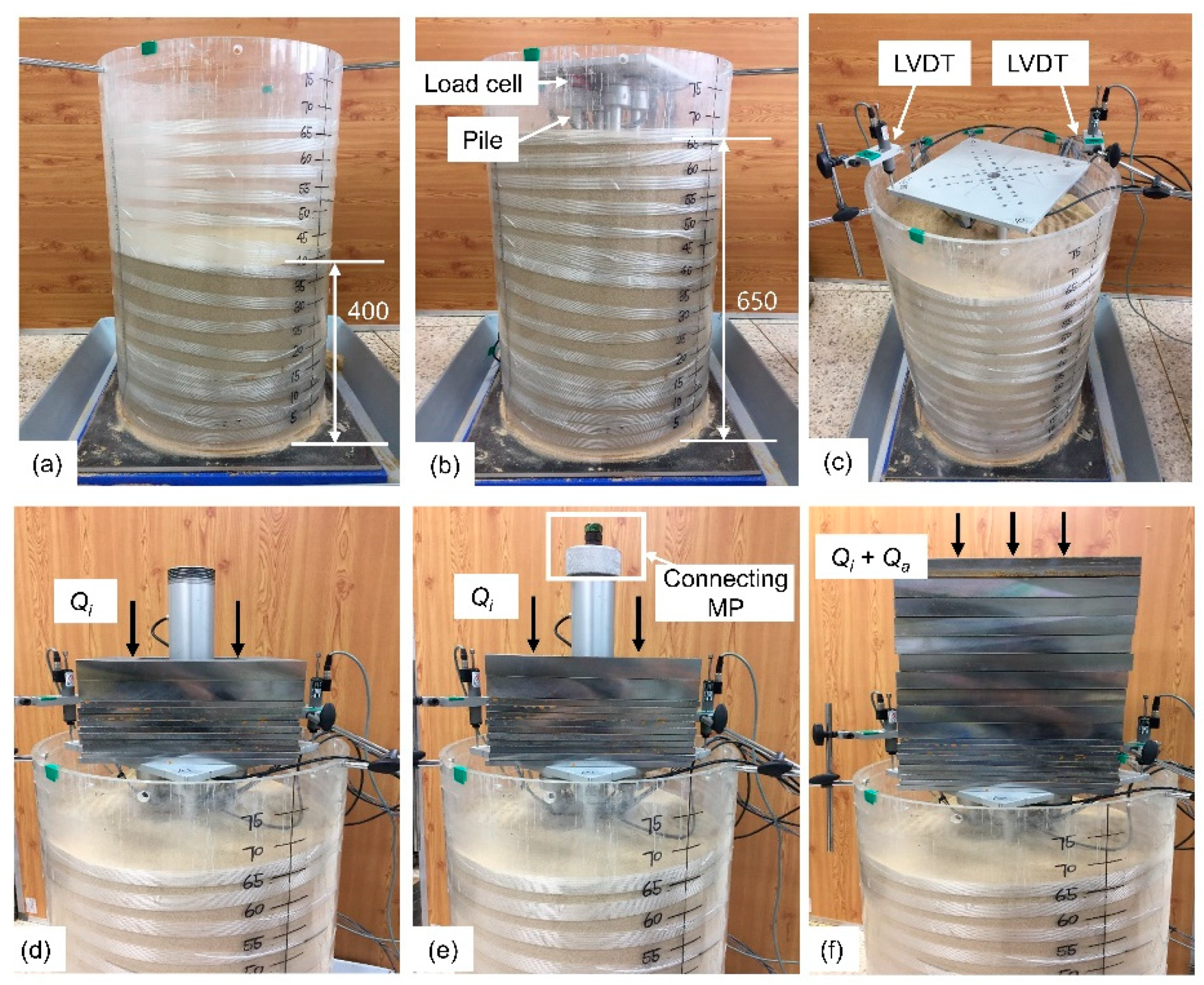
Two series of loadings tests were conducted in this study. Single pile loading tests were carried out to estimate the bearing capacity and axial stiffness of 5 single model piles. Each single pile installed in the center of the soil tank was subjected to the vertical loading until failure. Single piles were loaded by loading weights incrementally. Then, underpinned foundation loading tests were performed to evaluate the total settlement of the foundation underpinned with 5 types of micropile and load sharing of existing piles and micropiles during the initial and additional loading stage. Figure 4 illustrates the setup of the underpinned foundation loading tests. As there were some difficulties in installing micropiles after the initial loading to the existing foundation, micropiles were installed with the installation of PCP and raft but not connected to the raft. Micropiles were connected to the foundation after initial loading and then additional loads Qa were applied to the underpinned foundation. To ensure the repeatability and reliability of tests, each experimental case was carried out at least 3 times.
3. Results and Discussion
3.1. Single Pile Loading Test
Figure 5 shows axial load–settlement results for five single test piles. The ultimate bearing capacity (Qult) of a pile was considered to be the load required to displace its head by 10% of its diameter [41]. A safety factor of 3 was applied to calculate the allowable bearing capacity (Qall) of the piles. The estimated bearing capacities of the test piles are listed in Table 2, which shows that WMP1 had the largest bearing capacity followed in order by CMP1, WMP2, PCP, and CMP2. The axial stiffness of each pile, Kslope was evaluated from the initial slope (the linear part) of the load settlement curve as shown in Figure 3 and Table 2 [19,42]. The results show that WMP with shear keys was stiffer than CMP. Randolph and Wroth proposed the following analytical solution for calculating a pile’s axial stiffness under vertical loading [43]:
where r0 is the pile radius; ζ = ln(rm/r0); rm = 2.5ρ(1 − ν)L; ξ = Esl/Esb (ξ = 1 in this study); ρ = Esav/Esl (ρ = 0.5 in this study); μL = [2/(ζλ)]0.5(L/r0); λ = Ep/G; η = rb/r0 (η = 1 for PCP and CMP; η = 1.67 for WMP); rb is the radius at the pile’s base; L is pile length; Esl is the Young’s modulus of soil at the pile toe level; Esb is the Young’s modulus of soil below the pile tip; Esav is the average soil Young’s modulus along the pile shaft; ν is the Poisson’s ratio of the soil; G is shear modulus of the soil at the pile toe level; and Ep is the Young’s modulus of the pile material. Note that the calculation of the waveform micropile’s stiffness had a shaft diameter of 16.7 mm [44].
The stiffness of each pile was calculated by using Equation (2), Keq, which is also listed in Table 2. The calculated values are similar to the estimated Kslope values from the load settlement curves.
3.2. Underpinned Foundation Behavior
A loading test on a raft with four PCP without underpinning foundation was conducted first. The test result used as a reference loading for comparison with the results for loading test with underpinning foundation. Subsequent tests considered underpinned foundations with initial and additional loading. A Qi of 730 N (the summation of the four PCP’s bearing capacities) was applied to the existing foundations. After the addition of the micropile, Qa was gradually applied to the underpinned foundation, up to 150% of Qi (1825 N).
3.2.1. Load Settlement Behavior of Underpinned Foundations
Figure 6 shows the load settlement behavior of foundations underpinned with four types of micropile during the initial and additional loading stages. The response curves clearly changed at the point that the micropile is connected. The load settlement behavior in the initial loading stage is mainly attributed to the behavior of four PCP. As mentioned before, the micropile was installed before initial loading, as soil disturbance and experimental error may influence the load settlement behavior of the foundations before underpinning. As shown in Figure 6, the stiffness of the foundation after the connection of a micropile was larger than that in the initial loading stage without underpinning. The settlement in the cases underpinned with WMP1, CMP1, WMP2, and CMP2 at the final loading stage (1825 N) was 0.88, 1.02, 1.03, and 1.43 mm, respectively. Underpinning in each case reduced settlement by 63%, 54%, 54%, and 35%, respectively, in comparison with the case without underpinning. These results clearly demonstrate that the settlement reduction increased with the increasing axial stiffness of the micropile.
Makarchian and Poulos proposed a simplified method for estimating the ratio χ of the stiffness of the existing foundation to that of the underpinned foundation [20]. This ratio provides an overview of the effectiveness of the pile installation for underpinning the shallow foundation. It is calculated as follows:
where RSR is the ratio of settlement reduction; STFP is the total final settlement of the foundation underpinned by piles; Sti is total settlement of the existing foundation at the time ti of underpinning; STF is the final settlement of the existing foundation without underpinning; and Us is the degree of total settlement.
Figure 7 shows the reduction in final settlement (RSR) observed under maximum loading with respect to the stiffness ratio of the existing foundation and the underpinned foundation. The theoretical curve from Makarchian and Poulos is also plotted for comparison. The contribution of χ to the reduction of the foundation’s final settlement is significant. The reduction of the final settlement of foundations increased linearly with the increase of the underpinned foundation’s stiffness, which is in agreement with the findings of Makarchian and Poulos [20].
3.2.2. Axial Load Transfer Mechanism in Micropiles
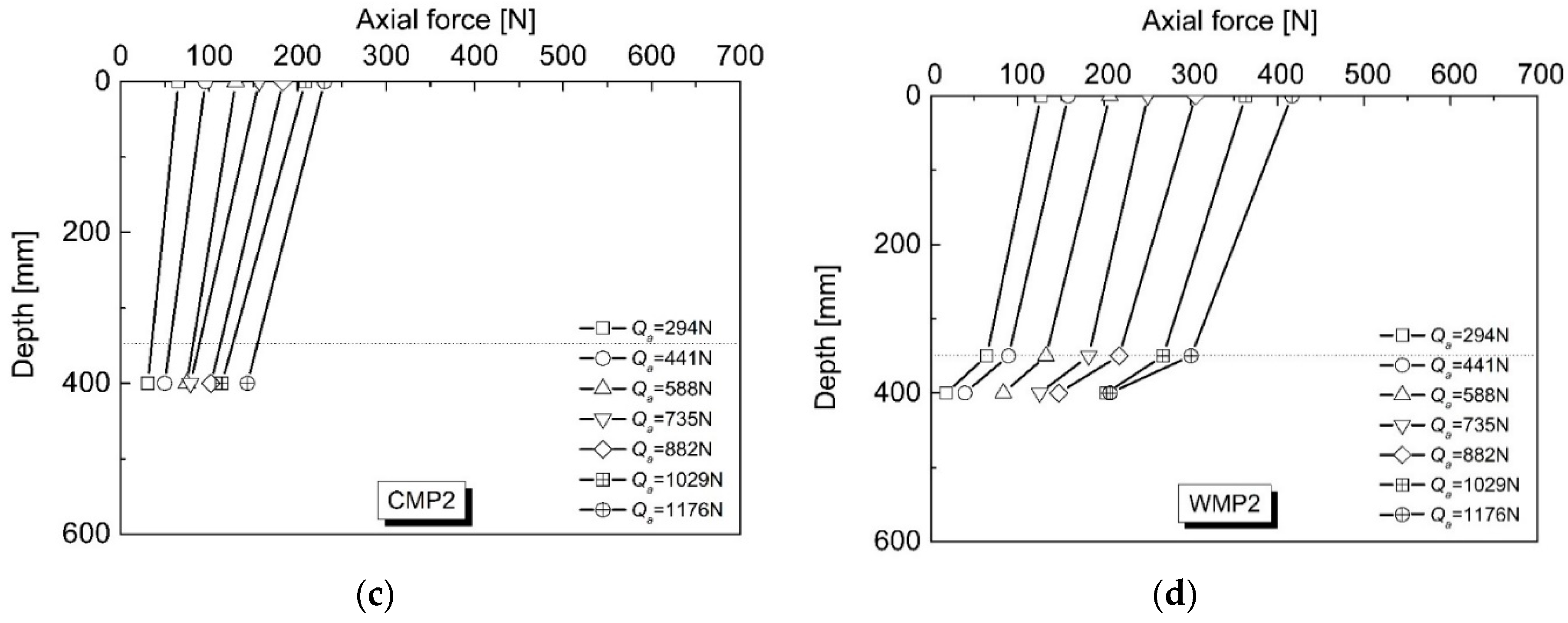
Strain measurement results provided the axial force at certain depths in each micropile under additional loading, Qa, from 294 to 1176 N. Figure 8 shows the results, revealing that the axial force of the micropile increased with the applied load and decreased with depth owing to the initiation of skin friction. The reduction of axial force along the micropile was more prominent in the dense soil layer than in the loose soil layer. Comparing piles CMP1 and WMP1 (with the same length but different shapes) shows that WMP1 (with shear keys) carried a greater load than CMP1 under a given applied load. This is attributed to its high axial stiffness. It also showed a more obvious increase in shaft resistance than CMP1, especially in the dense soil layer from 350 to 500 mm. This finding indicates that shear keys along the pile increased its shaft resistance. This effect was more significant in the soil region with a higher confining pressure, which is in good agreement with the results of Jang and Han [36,37]. Interestingly, WMP2 provided a similar shaft resistance to CMP1 despite being only about 80% of its length. This also confirmed that shear keys significantly influenced shaft resistance. This result also implies that under the additional loading to the underpinned foundation, the load carrying capacity and bearing resistance of the micropile increased with its increasing axial stiffness.
Figure 9 depicts the relation between the total shaft resistance of the underpinning micropiles and the applied additional loads. The shaft resistance was evaluated as the difference between the vertical load of the pile head and the axial force at the pile tip evaluated by the strain data. The shaft resistance of WMP1 increased sharply by increasing the applied load and at the final loading level, the mobilized shaft resistance was about 2.5 times that of CMP1 and WMP2. The shaft resistance of WMP2 and CMP1 increased slowly with the increasing load, and both showed almost identical behavior, indicating that the shear keys along the pile’s shaft significantly increased the shaft resistance, as explained by Jang and Han [37]. The shaft resistance of CMP2 also increased slowly with the applied load and the increase is the smallest measured here for these micropiles. After the shaft resistance reached to a certain value of 8 N, which occurred under an applied load of 735 N, the line flattened, implying that the shaft resistance was fully mobilized.
The tip resistance was determined from the strain gauge near the tip of each micropile. It is plotted for the underpinning micropiles under additional loading in Figure 10. With the exception of WMP1, the tip resistance of all the piles increased steadily with the increase of the applied load. Moreover, the increasing rate of tip resistance significantly increased for micropiles as the applied load exceeded 441 N. This result implies that the skin friction was mobilized prior to the tip resistance. The tip resistances of CMP1 and WMP2 were the highest measured here and both showed similar progressions. In the case of WMP1, the tip resistance was not mobilized at loading below 800 N, which suggests that up to that point, the load was not transferred to the tip owing to the effect of high shaft resistance. This indicates that the effect of shear keys along the pile’s shaft increased the shaft resistance, especially in dense sand.
3.2.3. Comparison of Underpinning Piles’ Load Sharing Behavior
Underpinning by micropiles aims to share partial loads caused by vertical construction in order to ensure the stability of existing foundations. Therefore, understanding the load sharing capacity of each pile is key to effective underpinning design. The load sharing ratio (LSR) is used to evaluate a pile’s load sharing capacity, and is defined as follows:
where QEP is the carried load of an existing pile under additional loading; QUP is the carried load of an underpinning pile under additional loading; Qa is the additional applied load to the underpinned foundation; LSREP is the load sharing ratio of an existing pile under additional loading; and LSRUP is the loading sharing ratio of an underpinning pile under additional loading.
Variables such as soil strength and pile type and stiffness affect the load sharing capacity of the pile. Ji et al. (2018, 2019) proposed a simplified model for reliability analysis of uncertainties influencing the design of slopes [45,46]. The present study considered only the effects of axial stiffness on the load sharing behavior of each pile. Figure 11 presents the load sharing by each micropile under additional loads applied to the underpinned foundation. The load sharing ratio of the underpinning piles increased with the applied load. The load sharing ratio for CMP2 increased the most slowly and converged to around 12.5% as the final load of 235 N exceeded its ultimate bearing capacity of 141 N. In contrast, the other pile models showed continuous increases of the load sharing ratio. At the final loading step, the load sharing ratios of WMP1, CMP1, and WMP2 were 34%, 24%, and 22% of the additional load, respectively. Figure 12 shows the normalized load sharing ratio of the underpinning piles to an existing pile with an increase in the additional applied load. The results show that load sharing ratios of WMP1, CMP1, and WMP2 increased to over 5, 2.5, and 2 times that of the existing pile, respectively, while CMP2 appeared to share the load almost equally with the existing pile. This clearly demonstrates that the load sharing capacity of a micropile increased with its increasing axial stiffness.
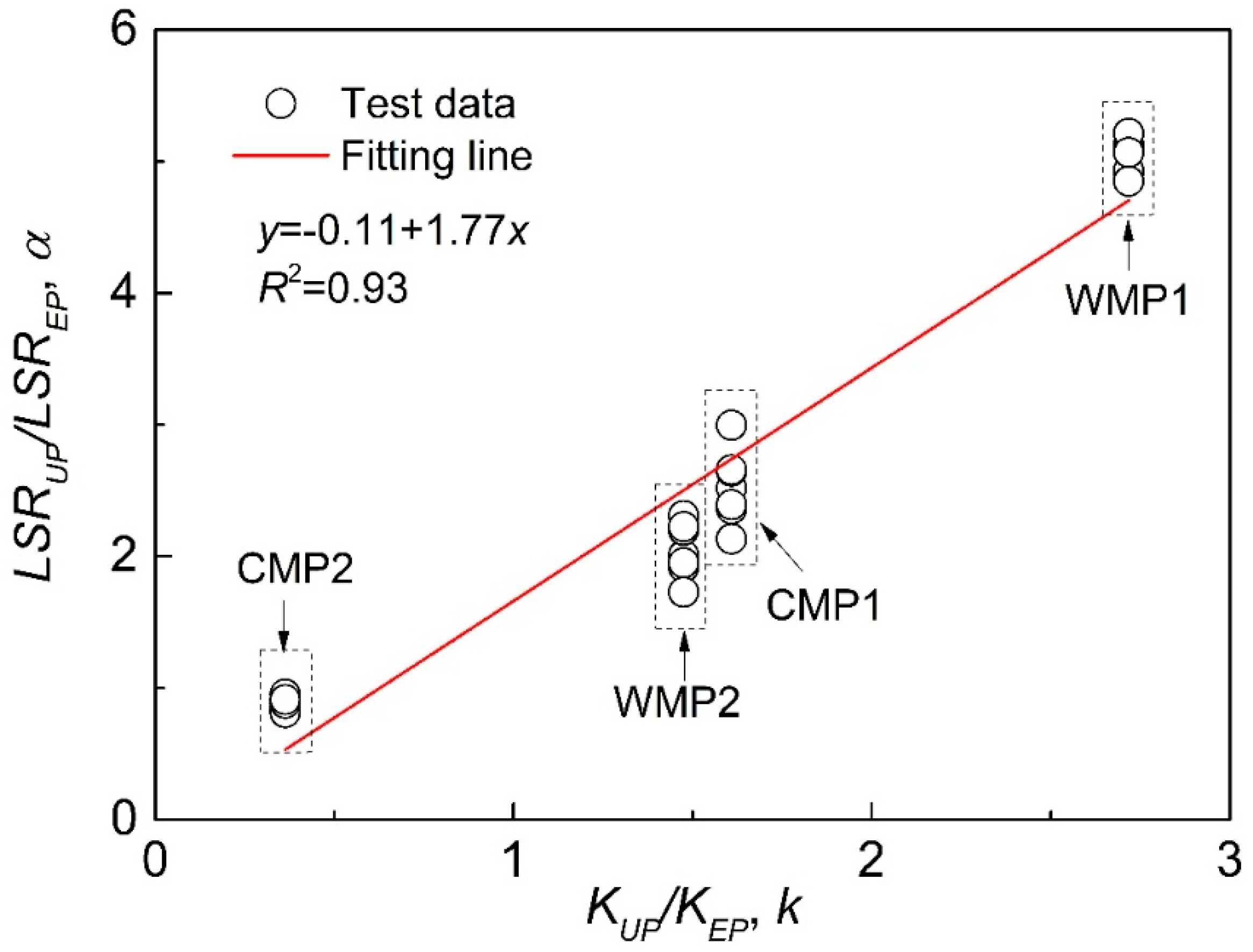
The load sharing of piles are generally determined by structural analysis software such as Midas. Such software that are for the design of foundation underpinning consider piles as springs with an input parameter of axial stiffness. Therefore, a pile’s stiffness is an important factor influencing its load sharing capacity. To evaluate quantitatively the effect of the stiffness on the load sharing capacity of each pile, the relationship between the normalized LSR of an underpinning pile to the existing pile, α, and the normalized stiffness of the underpinning pile to the existing pile, k, is illustrated in Figure 13 and Table 2. Figure 13 shows WMP1 to have the highest α and k. The normalized LSR of CMP1 and WMP2 were similar because of their similar axial stiffness. The plot shows α to increase linearly with k with a gradient about 1.8. This implies that underpinning by waveform micropiles or increasing the underpinning piles’ stiffness is an effective way to enhance the load sharing capacities of underpinning piles, which can contribute to reducing the number of underpinning piles required, and thus save construction cost. This finding could be used as a reference when designing underpinning pile schemes.
4. Conclusions
This study evaluated the effect of underpinning piles’ axial stiffness on the existing and underpinning pile’s load sharing behavior during the construction of vertical extensions to existing buildings. A series of model tests was performed by placing underpinning micropiles at the center of a 2 × 2 array of existing piles. The results led to the following conclusions:
(1) Single pile loading tests found the newly developed waveform micropile to show higher axial stiffness and load bearing capacity than a conventional micropile owing to the effect of shear keys along its shaft that increase the pile’s shaft resistance;
(2) Underpinning with micropiles reduced the total settlement of the foundations. The degree of settlement reduction increased linearly with the increment of the micropile’s stiffness. The relationship between the settlement reduction and micropile’s stiffness from the experiment agreed well with the theory of Makarchian and Poulos [20]. This result implies that additional data through future study can be used to propose the predictive equation for the design of underpinning pile foundations;
(3) The load sharing capacity of a micropile increased with applied loads. Increasing the axial stiffness of a micropile increased its load sharing capacity under an applied load. The waveform micropile had a larger load sharing capacity than a conventional micropile due to the effect of its shear keys increasing the axial stiffness and load bearing capacity;
(4) The normalized load sharing ratio increased linearly with the normalized stiffness ratio of the underpinning pile to the existing pile, with a gradient of about 1.8. This implies that increasing the underpinning pile’s stiffness is an effective method to enhance its load sharing capacity. This could reduce the number of underpinning piles required and reduce construction costs.
This work could be a reference for the practical design of underpinning guidelines. In addition, as small-scale tests are limited due to the stress level effect, the practical applicability of these model test results would be enhanced by further studies employing centrifuge tests and numerical analysis.
Author Contributions
Conceptualization, J.-T.H., C.W. and Y.-E.J.; experimental methodology, C.W.; validation, J.-T.H. and Y.-E.J.; formal analysis, C.W., J.-T.H. and Y.-E.J.; writing—original draft preparation, C.W.; writing—review and editing, Y.-E.J.; supervision, J.-T.H.
Funding
This research was funded by (19RERP-B099826-05) from Residential Environment Research Program (RERP) funded by Ministry of Land, Infrastructure and Transport of Korean government.
Conflicts of Interest
The authors declare no conflict of interest.
References
- Butcher, A.P.; Powell, J.J.M.; Skinner, H.D. Reuse of Foundations for Urban Sites—Foundation Reuse Best Practice Handbook; BRE Press: Watford, UK, 2006. [Google Scholar]
- Chapman, T.; Anderson, S.; Windle, J. Reuse of Foundations CIRIA 653; CIRIA: London, UK, 2007; ISBN 978-086017-653-4. [Google Scholar]
- Laefer, D.F. Quantitative support for a qualitative foundation reuse assessment tool. In Proceedings of the Geo-Frontiers 2011: Advances in Geotechnical Engineering, Dallas, TX, USA, 13–16 March 2011; pp. 113–121. [Google Scholar]
- MOLIT. Housing Act; Korea Ministry of Land, Infrastructure and Transport: Sejong, Korea, 2013. (In Korean)
- Thorburn, S.; Hutchison, J. Underpinning; Surrey University Press: Glasgow, UK, 1985. [Google Scholar]
- Bruce, D.A. In-situ Earth Reinforcing by Soil Nailing. In Underpinning and Retention; Springer: New York, NY, USA, 1993; pp. 340–394. [Google Scholar]
- Cole, K.W. Conventional Piles in Underpinning. In Underpinning and Retention; Springer: New York, NY, USA, 1993; pp. 63–83. [Google Scholar]
- Lizzi, F. “Pali Radice” Structures. In Underpinning and Retention; Springer: New York, NY, USA, 1993; pp. 84–156. [Google Scholar]
- Van der Stoel, A.E.C. Grouting for Pile Foundation Improvement; Delft University Press: Delft, The Netherlands, 2001. [Google Scholar]
- Lizzi, F. The Static Restoration of Monuments: Basic Criteria, Case Histories: Strengthening of Buildings Damaged by Earthquakes; Sagep: Genova, Italy, 1982; p. 146. [Google Scholar]
- Han, J. Principles and Practice of Ground Improvement; John Wiley & Sons: New York, NY, USA, 2015. [Google Scholar]
- Bruce, D.A. Aspects of minipiling practice in the United States. J. Ground Eng. 1989, 22, 35–39. [Google Scholar]
- Bruce, D.A.; Diaillio, A.F.; Juran, I. Micropiles: The state of practice. Ground Improv. 1997, 1, 25–35. [Google Scholar] [CrossRef]
- FHWA. Micropile Design and Construction Guidelines; US Department of Transportation: Washington, DC, USA, 2005.
- Han, J.; Ye, S.L. A Field Study on the Behavior of micropiles in clay under compression or tension. Can. Geotech. J. 2006, 43, 19–29. [Google Scholar] [CrossRef]
- Esmaeili, M.; Nik, M.G.; Khayyer, F. Experimental and Numerical Study of Micropiles to Reinforce High Railway Embankments. Int. J. Geomech. 2013, 13, 729–744. [Google Scholar] [CrossRef]
- Tsukada, Y.; Miura, K.; Tsubokawa, Y.; Otani, Y.; You, G.L. Mechanism of Bearing Capacity of Spread Footings Reinforced with Micropiles. Soils Found. 2006, 46, 367–376. [Google Scholar] [CrossRef] [Green Version]
- KHS. Korea Highway Bridge Design Standard, Explanation; KHS: Dortmund, Germany, 2008; pp. 885–887. [Google Scholar]
- JGJ. Technical Code for Improvement of Soil and Foundation of Existing Buildings; JGJ: Beijing, China, 2012. (In Chinese) [Google Scholar]
- Makarchian, M.; Poulos, H.G. Simplified Method for Design of Underpinning Piles. J. Geotech. Eng. 1996, 122, 745–751. [Google Scholar] [CrossRef]
- Han, J.; Ye, S.L. A Field Study on the Behavior of a Foundation Underpinned by Micropile. Can. Geotech. J. 2006, 43, 30–42. [Google Scholar] [CrossRef]
- El Kamash, W.; Han, J. Numerical analysis of existing foundations underpinned by micropile. Int. J. Geomech. 2016, 17. [Google Scholar] [CrossRef]
- Jang, Y.E.; Han, J.T. Development on the Micropile for Applying to Artificial Ground above Railroad Site. Adv. Sci. Technol. Lett. 2014, 55, 43–46. [Google Scholar]
- Turner, J.P.; Kulhawy, F.H. Physical Modeling of Drilled Shaft Side Resistance in Sand. Geotech. Test. J. 1994, 17, 282–290. [Google Scholar]
- Poulos, H.G.; Chen, L.T.; Hull, T.S. Model Tests on Single Piles Subjected to Lateral Soil Movement. Soils Found. 1995, 35, 85–92. [Google Scholar] [CrossRef] [Green Version]
- Pan, J.L.; Goh, A.T.; Wong, K.S.; Teh, C.I. Model tests on single piles in soft clay. Can. Geotech. J. 2000, 37, 890–897. [Google Scholar] [CrossRef]
- Lee, S.; Chung, C.K. An Experimental Study of the Interaction of Vertical Loaded Pile groups in Sand. Can. Geotech. J. 2005, 42, 1485–1493. [Google Scholar] [CrossRef]
- Al-Mahdi, A.I. Experimental investigation of the behavior of pile groups in sand under different loading rates. Geotech. Geol. Eng. 2006, 24, 889–902. [Google Scholar]
- Baziar, M.H.; Ghorbani, A.; Katzenbach, R. Small-Scale Model Test and Three-Dimensional Analysis of Pile-Raft Foundation on Medium-Dense Sand. Int. J. Civ. Eng. 2009, 7, 170–175. [Google Scholar]
- El Sawwaf, M. Experimental Study of Eccentrically Loaded Raft with Connected and Unconnected Short Piles. J. Geotech. Geoenviron. Eng. 2010, 136, 1394–1402. [Google Scholar] [CrossRef]
- El Garhy, B.; Galil, A.A.; Youssef, A.F.; Raia, M.A. Behavior of raft on settlement reducing piles: Experimental model study. J. Rock Mech. Geotech. Eng. 2013, 5, 389–399. [Google Scholar] [CrossRef] [Green Version]
- Elwakil, A.Z.; Azzam, W.R. Experimental and numerical study of piled raft system. Alex. Eng. J. 2016, 55, 547–560. [Google Scholar] [CrossRef] [Green Version]
- Rollins, K.M.; Olsen, K.G.; Jensen, D.H.; Garrett, B.H.; Olsen, R.J.; Egbert, J.J. Pile Spacing Effects on Lateral Pile Group Behavior: Analysis. J. Geotech. Geoenviron. Eng. 2006, 132, 1272–1283. [Google Scholar] [CrossRef]
- Das, B.M. Principles of Foundation Engineering; Cengage Learning: Andover, UK, 2015. [Google Scholar]
- Jang, Y.E.; Han, J.T. Study of Load Capacity of Waveform Micropile by Centrifuge test. In Proceedings of the 25th International Offshore and Polar Engineering Conference, Kona, HI, USA, 21–26 June 2015. [Google Scholar]
- Jang, Y.E.; Han, J.T. Field Study on Axial Bearing Capacity and Load Transfer Characteristic of Waveform Micropile. Can. Geotech. J. 2018, 55, 653–665. [Google Scholar] [CrossRef]
- Jang, Y.E.; Han, J.T. Analysis of the Shape Effect on the Axial Performance of a Waveform Micropile by Centrifuge Model Tests. Acta Geotech. 2019, 14, 505–518. [Google Scholar] [CrossRef]
- Wood, D.M. Geotechnical Modelling; CRC Press: London, UK, 2014. [Google Scholar]
- Iai, S. Similitude for Shaking Table Test on Soil-structure-fluid Model in 1g Gravitational Field. Soils Found. 1998, 29, 105–118. [Google Scholar] [CrossRef]
- Park, L.K.; Suneel, M.; Chul, I.J. Shear Strength of Jumunjin Sand According to Relative Density. Mar. Georesour. Geotechnol. 2008, 26, 101–110. [Google Scholar] [CrossRef]
- EN, B.S. Eurocode 7: Geotechnical Design—Part 1: General Rules; British Standards: London, UK, 2004. [Google Scholar]
- Ahmed, A.; El Naggar, M.H.; El Naggar, H. Performance of micropiled raft in clay subjected to vertical concentrated load: Centrifuge modeling. Can. Geotech. J. 2015, 52, 2017–2029. [Google Scholar]
- Jang, Y.E.; Kim, B.M.; Wang, C.C.; Han, J.T. Prediction of vertical bearing capacity of waveform micropile. Geotech. Lett. 2019. accepted. [Google Scholar]
- Randolph, M.R.; Wroth, C.P. An Analysis of the Vertical Deformation of Pile Groups. Geotechnique 1979, 29, 423–439. [Google Scholar] [CrossRef]
- Ji, J.; Zhang, C.S.; Gao, Y.F.; Kodikara, J. Effect of 2D Spatial Variability on Slope Reliability: A Simplified FORM Analysis. Geosci. Front. 2018, 9, 1631–1638. [Google Scholar] [CrossRef]
- Ji, J.; Zhang, C.S.; Gao, Y.F.; Kodikara, J. Reliability-based design for geotechnical engineering: An inverse FORM approach for practice. Comput. Geotech. 2019, 111, 22–29. [Google Scholar] [CrossRef]
Figure 1.
Construction procedure for the underpinning with the consideration of additional loading. (a) Existing foundation (EP) subjected to superstructural load (Qi); (b) boring; (c) underpinning by new pile (UP); and (d) additional loads (Qa) applied on underpinned foundation.
Figure 1.
Construction procedure for the underpinning with the consideration of additional loading. (a) Existing foundation (EP) subjected to superstructural load (Qi); (b) boring; (c) underpinning by new pile (UP); and (d) additional loads (Qa) applied on underpinned foundation.

Figure 2.
Schematic of experimental set-up. (a) Elevation view; (b) top view.
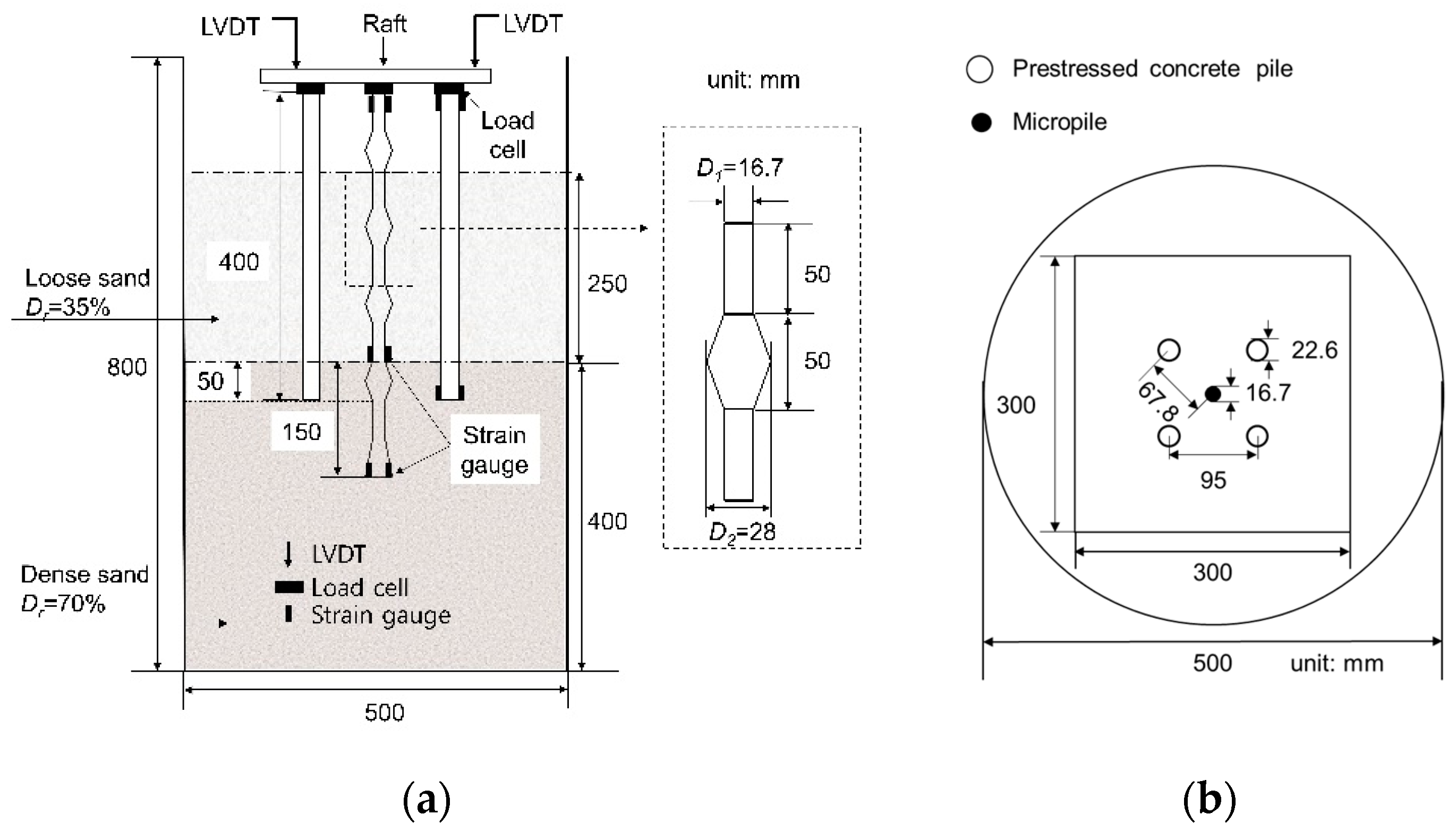
Figure 3.
Model piles with attachment of strain gauges.
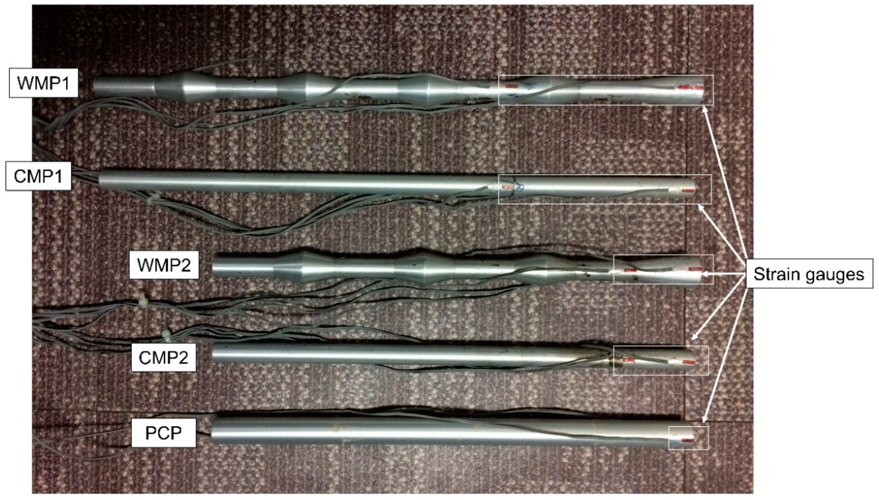
Figure 4.
Experimental set-up for underpinned foundation loading test. (a) Preparation of loose sand layer; (b) installation of pile foundation and preparation of dense sand layer; (c) installation of linear variable differential transformers (LVDTS); (d) initial loading Qi to existing foundation; (e) connection of micropile to existing foundation; and (f) additional loading Qa to underpinned foundation.

Figure 5.
Load settlement behavior of single piles (s1 is 0.1D of micropile; s2 is 0.1D of PCP).

Figure 6.
Comparison of load settlement behavior on the raft during initial loading and additional loading on the underpinned foundation.
Figure 6.
Comparison of load settlement behavior on the raft during initial loading and additional loading on the underpinned foundation.

Figure 7.
Relation between the reduction of foundation settlement by the underpinned foundation and the normalized stiffness of the existing foundation.
Figure 7.
Relation between the reduction of foundation settlement by the underpinned foundation and the normalized stiffness of the existing foundation.
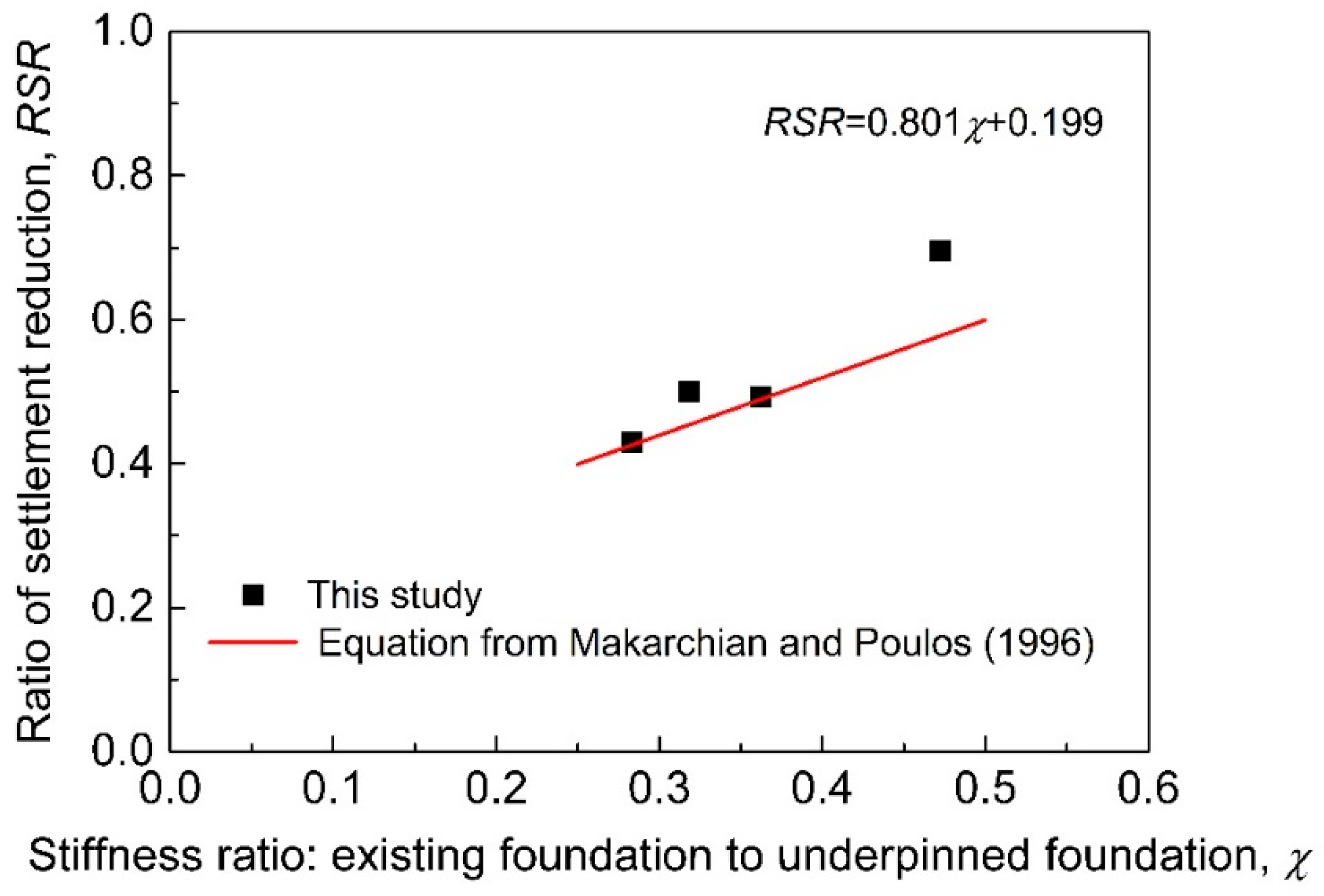
Figure 8.
Load transfer behavior of different types of micropile subjected to additional loads. (a) CMP1; (b) WMP1; (c) CMP2; and (d) WMP2.
Figure 8.
Load transfer behavior of different types of micropile subjected to additional loads. (a) CMP1; (b) WMP1; (c) CMP2; and (d) WMP2.
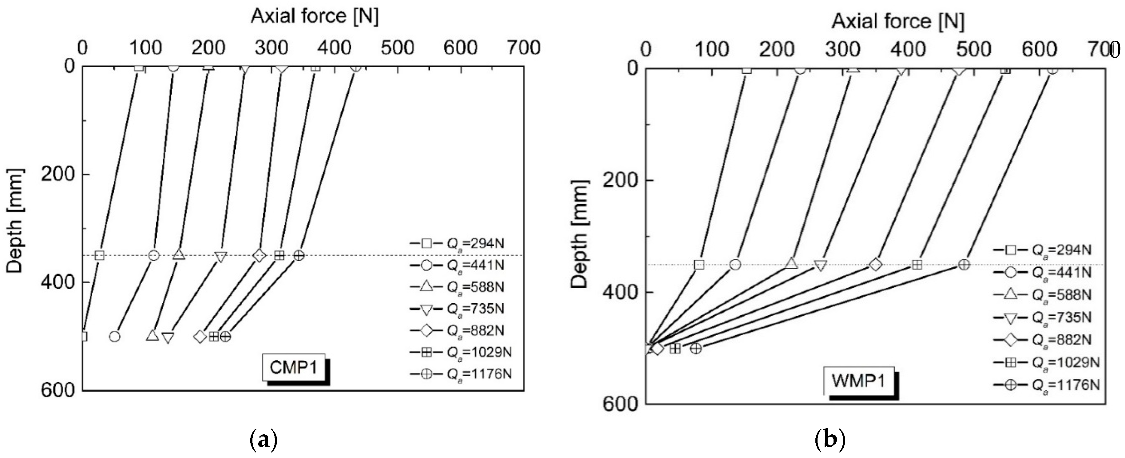

Figure 9.
Shaft resistance of the underpinning micropiles with respect to the additional load applied to the foundation.
Figure 9.
Shaft resistance of the underpinning micropiles with respect to the additional load applied to the foundation.
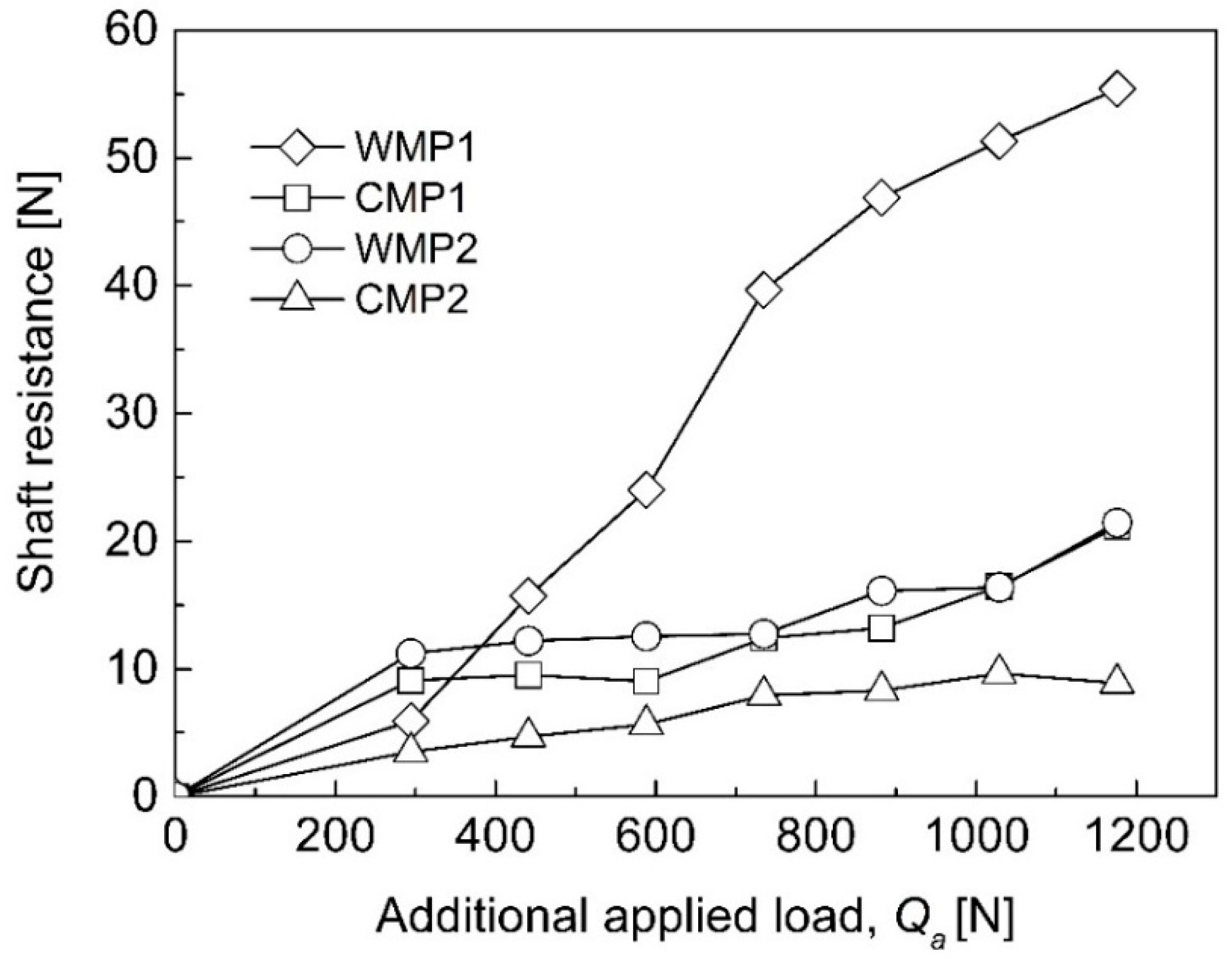
Figure 10.
Tip resistance of the underpinning micropiles with respect to the additional load applied to the foundation.
Figure 10.
Tip resistance of the underpinning micropiles with respect to the additional load applied to the foundation.

Figure 11.
Load sharing ratio (LSR) of underpinning pile with respect to additional loading level.
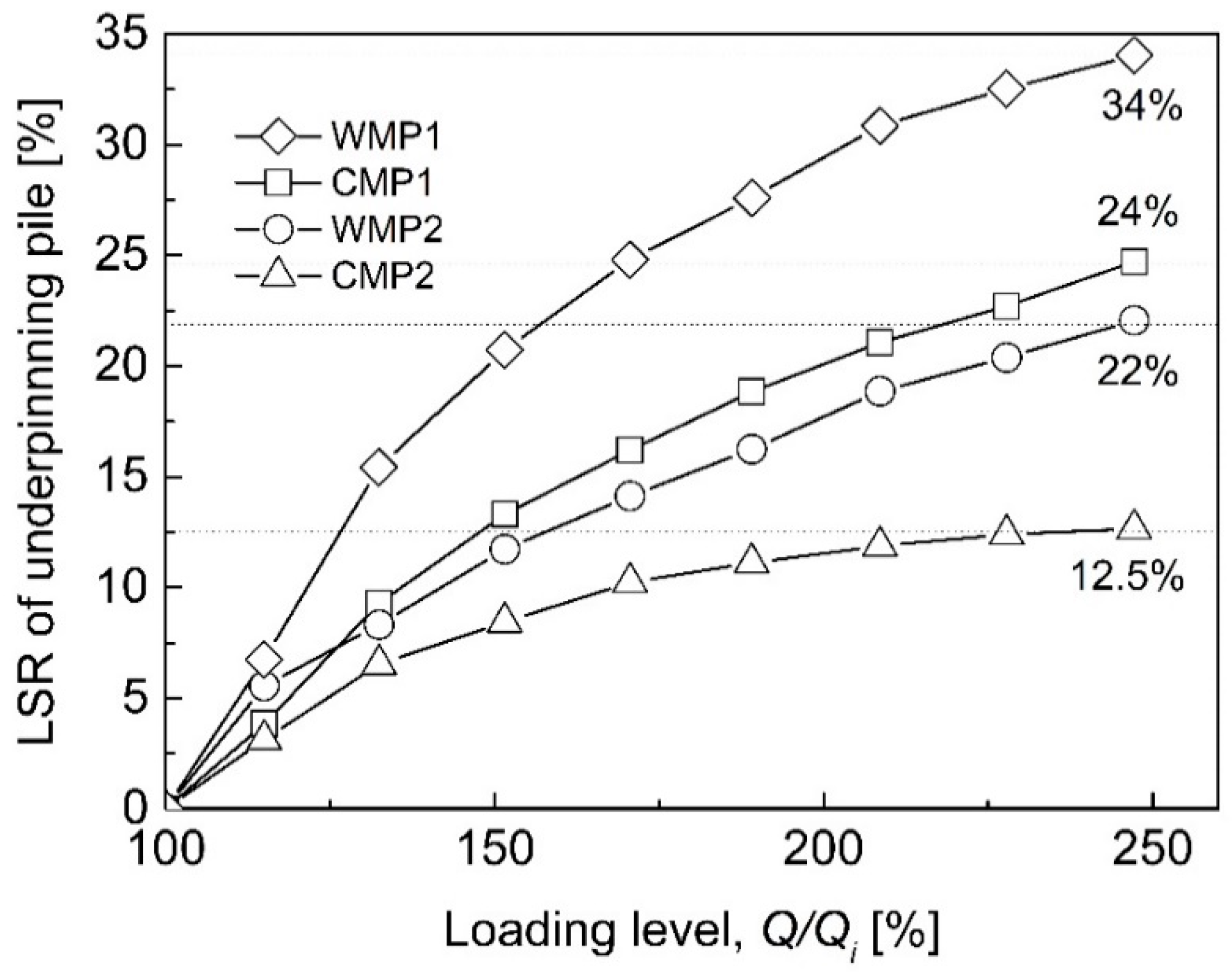
Figure 12.
Load sharing ratio of the underpinning pile (UP) normalized by that of the existing pile (EP) plotted with respect to the additional loading level.
Figure 12.
Load sharing ratio of the underpinning pile (UP) normalized by that of the existing pile (EP) plotted with respect to the additional loading level.
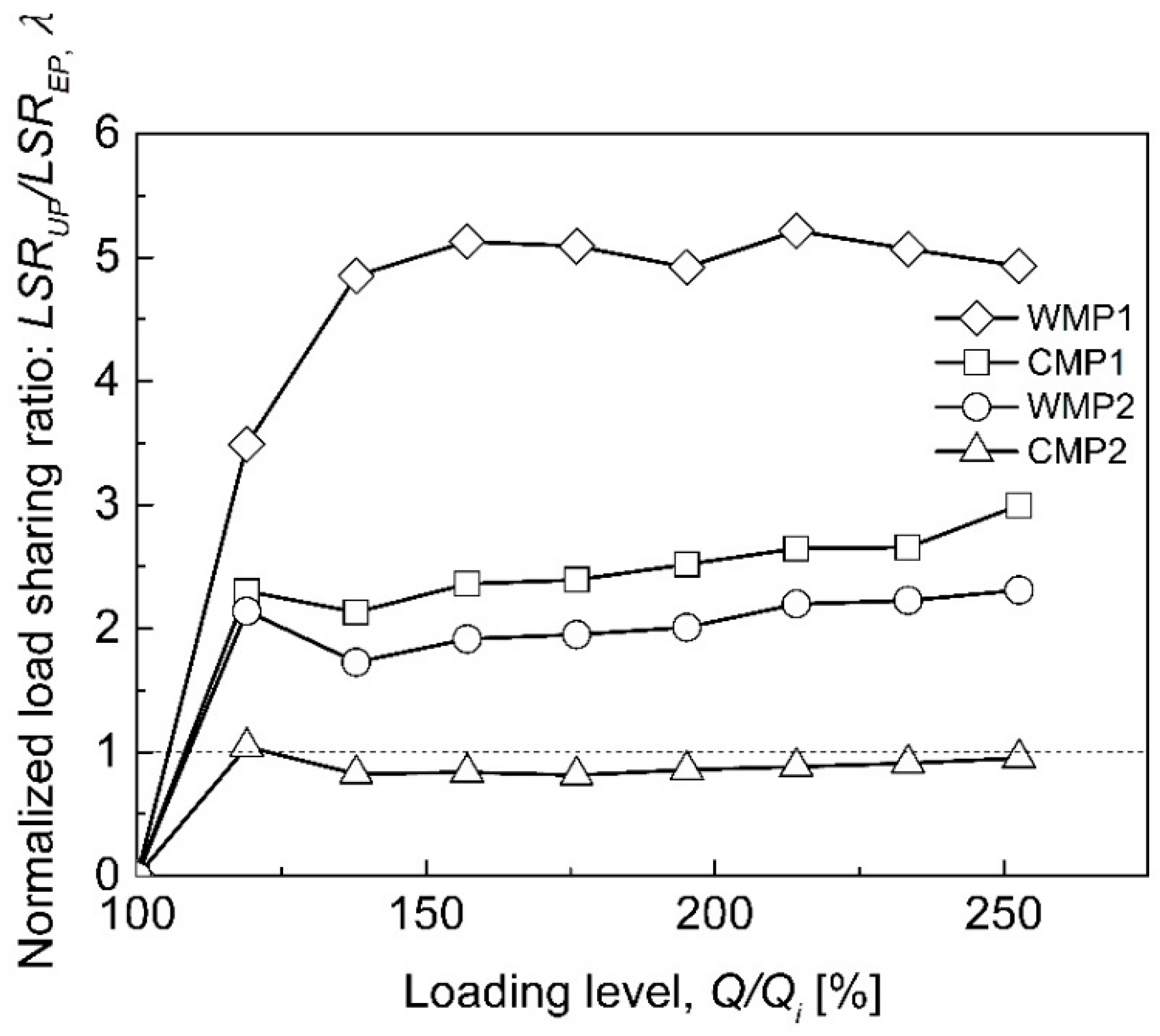
Figure 13.
Load sharing ratio of the underpinning pile normalized by that of the existing pile (α), plotted with respect to the stiffness ratio of the underpinning pile normalized by that of the existing pile (k).
Figure 13.
Load sharing ratio of the underpinning pile normalized by that of the existing pile (α), plotted with respect to the stiffness ratio of the underpinning pile normalized by that of the existing pile (k).

Table 1.
Size and properties of prototype and model piles.
| Pile | Type | Prototype Pile | Model Pile | ||||
|---|---|---|---|---|---|---|---|
| Diameter (mm) | Length (mm) | Young’s Modulus (GPa) | D (mm) | L (mm) | Young’s Modulus (GPa) | ||
| Existing pile (EP) | PCP | 350 | 8000 | 35 (Concrete) | 22.6 | 400 | 69 (Aluminum) |
| Underpinning pile (UP) | WMP1 1 | D1: 200 D2: 333 | 10,000 | 42.8 (Concrete + steel) | D1: 16.7 D2: 28 | 500 | |
| WMP2 2 | 8000 | 400 | |||||
| CMP1 3 | 200 | 10,000 | 16.7 | 500 | |||
| CMP2 4 | 8000 | 400 | |||||
1 Waveform micropile (WMP) with length of 500 mm; 2 Waveform micropile (WMP) with length of 400 mm; 3 Conventional micropile (CMP) with length of 500 mm;4 Conventional micropile (CMP) with length of 400 mm.
Table 2.
Bearing capacity and axial stiffness of model piles.
| Type | Underpinning Pile (UP) | Existing Pile (EP) | |||
|---|---|---|---|---|---|
| WMP1 | CMP1 | WMP2 | CMP2 | PCP | |
| Qult (N) | > 1000 | 998 | 612 | 141 | 460 |
| Qall (N) | > 333 | 332 | 204 | 47 | 153 |
| Kslope (N/mm) | 1500 | 888 | 814 | 200 | 552 |
| Keq (N/mm) | 1277 | 766 | 798 | 478 | 647 |
| K (KUP/KEP) | 2.70 | 1.60 | 1.47 | 0.36 | |
© 2019 by the authors. Licensee MDPI, Basel, Switzerland. This article is an open access article distributed under the terms and conditions of the Creative Commons Attribution (CC BY) license (http://creativecommons.org/licenses/by/4.0/).
Share and Cite
MDPI and ACS Style
Wang, C.; Han, J.-T.; Jang, Y.-E. Experimental Investigation of Micropile Stiffness Affecting the Underpinning of an Existing Foundation. Appl. Sci. 2019, 9, 2495. https://doi.org/10.3390/app9122495
AMA Style
Wang C, Han J-T, Jang Y-E. Experimental Investigation of Micropile Stiffness Affecting the Underpinning of an Existing Foundation. Applied Sciences. 2019; 9(12):2495. https://doi.org/10.3390/app9122495
Chicago/Turabian StyleWang, Chengcan, Jin-Tae Han, and Young-Eun Jang. 2019. "Experimental Investigation of Micropile Stiffness Affecting the Underpinning of an Existing Foundation" Applied Sciences 9, no. 12: 2495. https://doi.org/10.3390/app9122495
Note that from the first issue of 2016, this journal uses article numbers instead of page numbers. See further details here.