Ultra-Small Fiber Bragg Grating Accelerometer


1
School of Electronic and Electrical Engineering, Bengbu University, Bengbu, 233030 Anhui, China
2
Zhixing S&T Inc., Nantong, 226010 Jiangsu, China
*
Author to whom correspondence should be addressed.
Appl. Sci. 2019, 9(13), 2707; https://doi.org/10.3390/app9132707
Submission received: 7 March 2019
/
Revised: 8 April 2019
/
Accepted: 22 April 2019
/
Published: 3 July 2019
(This article belongs to the Special Issue Recent Progress in Fiber Optic Sensors: Bringing Light to Measurement)
Abstract
:Reducing the size of an accelerometer overcomes the tradeoff between its sensitivity and resonant frequency, and the theoretical relationships are analyzed. A fiber Bragg grating (FBG) accelerometer with the shortest vibration arm, 7 mm, among FBG accelerometers using the optical fiber to hold its inertial object is demonstrated here. The inertial object was 4.41 g. The experimental crest-to-trough sensitivity and resonant frequency, 244 pm/g and 90 Hz, disagree with the theoretical values, 633 pm/g and 67 Hz, perhaps due to the friction between the inertial object and shell. In order to find the theoretical values, a method to find the pre-stretch of the FBG is also presented here, based on the stretch of the FBG at equilibrium and the mass of the inertial object. The FFT program, experimental data and theoretical calculations are presented in detail in the Supplementary Material.
1. Introduction
Usually, there is an inertial object and a sensing element inside an accelerometer. The inertial object is held by a vibration arm (a stick or string, etc.) to vibrate around its equilibrium position. The sensing element is attached to the vibration arm, or is part of the vibration arm. When the inertial object vibrates, it pulls the vibration arm and sensing element. Usually, the working frequency range of an accelerometer is up to half of its resonant frequency, and the sensitivity of the accelerometer changes significantly above this frequency range [1].
The improvement of the sensitivity of an accelerometer can be obtained by using a heavier inertial object. However, this method will reduce the resonant frequency. By contrast, the improvement of the resonant frequency of an accelerometer can be obtained by shortening the vibration arm, without reducing the sensitivity. Therefore, it is optimum for the vibration arm to be as short as possible, provided that its inertial object is adequately heavy.
Fiber Bragg grating (FBG) has many intrinsic advantages, such as immunity to electromagnetic interference, electrical isolation, frequency modulation, and ease of multiplexing [2]. Many different FBG accelerometers have been developed [3,4,5,6,7,8,9,10,11,12,13,14,15]. Some FBG accelerometers used a springy stick to hold the inertial object at the equilibrium, and the FBG was attached to the springy stick [3,4,5,6]. When the inertial object vibrated, the springy stick and FBG was pulled. Some used a springy joint to hold the inertial object at the equilibrium, and the FBG was pulled when the inertial object vibrated [7,8,9,10,11]. The 10-mm vibration arm was the shortest among them, and the sensitivity and resonant frequency were 19 pm/g and 3000 Hz, respectively [9]. Some used optical fiber containing Bragg grating as the vibration arm, and usually showed a higher sensitivity and smaller size than other types [12,13,14,15].
Here, by using a 7-mm-long optical fiber containing Bragg grating as the vibration arm, we experimentally demonstrate an FBG accelerometer with the shortest vibration arm among similar structures, as far as we know. Table 1 compares such FBG accelerometers [12,13,14,15]. They are listed in order of the lengths of their vibration arms.
2. Theory
2.1. Relationships among the Sensitivity, Resonant Frequency and Length of the Spring
The resonant frequency of an accelerometer , where is the spring constant and the mass of the inertial object [1]. It shows that as the mass increases, the resonant frequency will decrease; as the spring becomes shorter, the spring constant and resonant frequency will increase.
The Static Sensitivity in terms of the Relative Displacement (SSRD) is , where and are the displacements of the inertial object and shell from their equilibrium positions, respectively [1]. SSRD is the length change of the spring at unit acceleration, and serves as a bridge to find the static sensitivity.
Assume that the length of the spring is halved ( is doubled) and the mass of the inertial object is doubled ( is doubled); the resonant frequency and SSRD will be unchanged. However, the static sensitivity will be doubled, if the sensing element is based on strain change instead of length change. Strain is the ratio of the length change to the original length. Even though SSRD (length change) is the same, the strain will be doubled if the original length is halved.
For example, FBG is based on its strain change. Assume that the length of an FBG accelerometer’s vibration arm is quartered ( is quadrupled). If the mass of the inertial object is the same, the resonant frequency will be doubled, the SSRD quartered, and the static sensitivity the same; if the mass of the inertial object is also quadrupled, the resonant frequency and SSRD will be the same, but the static sensitivity quadrupled.
2.2. Calculation of Pre-Stretch Based on the Mass and Stretch at Equilibrium
To find the sensitivity and resonant frequency of an FBG accelerometer based on transverse forces, it is necessary to have the pre-strain (or the pre-stretch in terms of the resonant wavelength change) of the FBG [1,15]. The pre-stretch is the stretch when the two ends of the FBG are fixed and the inertial object has not hung on the FBG. In the design of this accelerometer, as the ends of the FBG are fixed after the inertial object is hung, the pre-stretch needs to be calculated.
The pre-stretch can be calculated based on the mass of the inertial object and the stretch of FBG at equilibrium by simulation. Firstly, estimate the pre-stretch based on the mass and stretch at equilibrium. For example, if the mass is 4.41 g and the stretch at equilibrium is 1.38 nm, the pre-stretch can be estimated around 1 nm. Secondly, based on the estimated pre-stretch, calculate the induced-wavelength-change by the mass, 0.29 nm for the example above. If the total of the pre-stretch and induced-wavelength-change is smaller than the stretch at equilibrium, increase the estimated pre-stretch. Vice versa. The pre-stretch is 1.13 nm for the example above, and the calculations are given in the Supplementary Material. The parameters of the optical fiber used here are from [16].
3. Experiments
Figure 1 shows the packed FBG accelerometer in comparison with a coin. Its length, width and height were 23, 18 and 17 mm, respectively. The insets show the schematic diagrams of the inside. The FBG was fixed by its two ends, and an inertial object was hung in the middle. It was not fixed on the FBG, and could move almost freely along the FBG. The inertial object and shell were made of stainless steel. The distance between the two fixed ends of the FBG was 7 mm. The values used here were selected based on a few principles. Firstly, the Bragg grating should not be too short; otherwise, it may fail to provide adequate reflection for practical applications. Secondly, the distance between the two fixed ends should only be slightly longer than the length of the Bragg grating. The shorter the distance, the better the performance of an accelerometer. But the distance must be longer than the FBG to avoid chirping. Lastly, the inertial object should be heavier enough to overcome the friction, and its size should not be bulky, so the accelerometer can be compact.
Bearings were used to reduce the frictions between the inertial object and the shell. There were two bearings lined up horizontally on one side, and two vertically on the other side. This design may reduce the shaking of the inertial object.
This accelerometer was only sensitive in one transverse direction. The inertial object could move almost freely along the axial direction, only subjected to friction. Its motion in the other transverse direction is restricted by restricting the distance between the inertial object and shell.
The Bragg grating was 5 mm in length, 3 db bandwidth less than 0.3 nm, reflectivity 91%, side-mode suppression ratio 10 dB, and free state resonant wavelength 1529.05 nm (Da Hui Photoelectric Inc., Jinan, China). The resonant wavelength was 1530.43 nm at equilibrium after the inertial object was hung. The mass of the inertial object was 4.41 g. The stretch at equilibrium was 1530.43 − 1529.05 = 1.38 nm, which was due to both the pre-stretch when the FBG was fixed by its two ends and the stretch induced by the weight of the inertial object. The room temperature was within 10 to 25 °C during the experiments.
Figure 2 shows the experimental setup. The FBG accelerometer and a piezo accelerometer were put together on top of a shaker. The shaker was feed with a sinusoidal wave generated by a signal generator (MFG2160MR, Gwinstek Inc, Taiwan). Both accelerometers were sampled at 500 Hz. The Piezo accelerometer (CT1010L, Chengke Inc., Shanghai, China), connected to a constant current adaptor (CT5204, Chengke Inc., Shanghai, China), a Data Acquisition (DAQ) card (USB_HRF4626, Hengruifeng Inc., Suzhou, China), and a computer, shown a resolution of 0.001 g; the FBG interrogator (SAI-1127AF, Casstk Inc., Shenzhen, China) shown a resolution of 1 pm.
Figure 3 shows the results of the two accelerometers at 5 Hz at 6 different accelerations and their corresponding FFTs. The frequency of the input signal of the shaker was fixed at 5 Hz, and 6 different amplitudes were applied. Each amplitude was kept for several seconds, and then increased into next one. One second data were extracted for every acceleration, and their FFT were carried out. The 6 rows correspond with the 6 accelerations. The first column shows the FBG results, the second the FBG FFT results, the third the piezo results, and the fourth the piezo FFT results.
Figure 4 shows the sensitivity of the FBG accelerometer based on the FFT results of all the 6 accelerations. The FFT results of the piezo and FBG accelerometers at the 6 accelerations correspond with the horizontal and vertical coordinates of the 6 non-zero points. The FFT results give the amplitudes of the accelerations. The crest-to-though wavelength change is the twice of the amplitudes of the FBG FFT results. By making the fitting line pass through the origin, the sensitivity is its slope, in this case 244 pm/g. Perhaps due to the friction between the inertial object and shell or the lower accuracy of the shaker used here, the linearity 0.9984 obtained here is evidently lower than those obtained elsewhere by the same FFT method, where they were about 0.9999 in the working direction [13,15,17].
Figure 5 shows the frequency response of the FBG accelerometer. It was obtained in a similar way as above. However, the frequency of the input signal of the shaker was adjusted here, and the sensitivities (the ratio of wavelength change to acceleration) were calculated just based on one acceleration, instead of 6 accelerations. It shows that the resonant frequency was about 90 Hz.
4. Conclusions and Discussion
Theoretically, we have proved that a short vibration arm improves the resonant frequency without reducing the sensitivity, and demonstrated a method to find the pre-stretch in order to find the theoretical sensitivity and resonant frequency. The pre-stretch of the FBG in terms of the resonant wavelength change 1.13 nm is calculated based on the mass of the inertial object 4.41 g and the stretch at the equilibrium 1.38 nm. By using the pre-stretch and mass, the theoretical sensitivity and resonant frequencies are found, 633 pm/g and 67 Hz, respectively, based on the modified spring-mass theory [1,15].
Experimentally, an ultra-small FBG accelerometer with a 7 mm vibration arm has been demonstrated here. Its experimental crest-to-trough sensitivity and resonant frequency (244 pm/g and 90 Hz) disagree with the theoretical predictions (633 pm/g and 67 Hz), perhaps due to the friction between the inertial object and shell. The theoretical and experimental results agreed well when there were no frictions but only air resistances [13,15].
The vibration arm may be further shortened by using a shorter FBG; however, the friction between the inertial object and the shell must be well managed. Otherwise, the friction may significantly influence its performance, because the mass of the inertial object could be too light to overcome the friction to vibrate sinusoidally.
Temperature affects such FBG accelerometers in two ways, but the effects can be controlled. Temperature affects the length of the shell. As the FBG is fixed on the shell by its two ends, the pre-strain of the FBG will change along with the length of the shell. The sensitivity will change along with the pre-strain. However, it has been demonstrated that a 0.66 nm change in the pre-strain with a 5.71 g inertial object only changed the sensitivity by less than 10% [15]. The shell can be made by temperature insensitive material, such as 4j32 or 4j36, to reduce this temperature effect. Temperature also affects the effective refractive index of the optical fiber. However, the frequency of temperature change is so low that this temperature effect can be eliminated by using a high pass filter.
Supplementary Materials
The calculations are available online at https://www.mdpi.com/2076-3417/9/13/2707/s1.
Author Contributions
Conceptualization, methodology, FFT program, writing K.L.; validation, investigation, formal analysis, K.L., G.L., Y.L.; sensor shell and inertial object manufacturing, J.Y. and W.M.; visualization, Y.L. and J.Y.; project administration and funding acquisition, K.L., G.L., Y.L.
Funding
This research was funded by Bengbu University, grant number BBXY2018KYQD02, 2019ZR04zd, 2017ZR06 and 2017ZR10, and Anhui Province Education Department KJ2019A0853 and KJ2017A565.
Conflicts of Interest
The authors declare no conflict of interest.
References
- Li, K.; Chan, T.H.T.; Yau, M.H.; Nguyen, T.; Thambiratnam, D.P.; Tam, H.Y. Very sensitive fiber Bragg grating accelerometer using transverse forces with an easy over-range protection and low cross axial sensitivity. Appl. Opt. 2013, 52, 6401–6410. [Google Scholar] [CrossRef] [PubMed] [Green Version]
- Lee, B. Review of the present status of optical fiber sensors. Opt. Fiber Technol. 2003, 9, 57–79. [Google Scholar] [CrossRef]
- Berkoff, T.A.; Kersey, A.D. Experimental demonstration of a fiber Bragg grating accelerometer. IEEE Photon. Technol. Lett. 1996, 8, 1677–1679. [Google Scholar] [CrossRef]
- Todd, M.D.; Johnson, G.A.; Althouse, B.A.; Vohra, S.T. Flexural beam-based fiber Bragg grating accelerometers. IEEE Photon. Technol. Lett. 1998, 10, 1605–1607. [Google Scholar] [CrossRef]
- Laudati, A.; Mennella, F.; Giordano, M.; D’Altrui, G.; Tassini, C.C.; Cusano, A. A fiber-optic Bragg grating seismic sensor. IEEE Photon. Technol. Lett. 2007, 19, 1991–1993. [Google Scholar] [CrossRef]
- Basumallick, N.; Biswas, P.; Chakraborty, R.; Chakraborty, S.; Dasgupta, K.; Bandyopadhyay, S. Fibre bragg grating based accelerometer with extended bandwidth. Meas. Sci. Technol. 2016, 27, 035008. [Google Scholar] [CrossRef]
- Antunes, P.; Varum, H.; Andre, P. Uniaxial fiber Bragg grating accelerometer system with temperature and cross axis insensitivity. Measurement 2011, 44, 55–59. [Google Scholar] [CrossRef]
- Antunes, P.; Marques, C.A.; Varum, H.; Andre, P. Biaxial optical accelerometer and high-angle inclinometer with temperature and cross-axis insensitivity. IEEE Sens. J. 2012, 12, 2399–2406. [Google Scholar] [CrossRef]
- Stefani, A.; Andresen, S.; Yuan, W.; Herholdt-Rasmussen, N.; Bang, O. High Sensitivity Polymer Optical Fiber-Bragg-Grating-Based Accelerometer. IEEE Photon. Technol. Lett. 2012, 24, 763–765. [Google Scholar] [CrossRef]
- Zhang, Y.; Zhang, W.; Zhang, Y.; Chen, L.; Yan, T.; Wang, S.; Yu, L.; Li, Y. 2-d medium–high frequency fiber bragg gratings accelerometer. IEEE Sens. J. 2017, 17, 614–618. [Google Scholar] [CrossRef]
- Wang, J.; Wei, L.; Li, R.; Liu, Q.; Yu, L.; Tan, Y. An FBG-based 2-D Vibration Sensor with Adjustable Sensitivity. IEEE Sens. J. 2017, 17, 4716–4724. [Google Scholar] [CrossRef]
- Guo, Y.X.; Zhang, D.S.; Zhou, Z.D.; Xiong, L.; Deng, X.W. Welding-packaged accelerometer based on metal-coated FBG. Chin. Opt. Lett. 2013, 11, 070604. [Google Scholar]
- Li, K.; Chan, T.H.T.; Yau, M.H.; Thambiratnam, D.P.; Tam, H.Y. Biaxial fiber Bragg grating accelerometer using axial and transverse forces. IEEE Photon. Technol. Lett. 2014, 26, 1549–1552. [Google Scholar] [CrossRef]
- Li, T.; Tan, Y.; Zhou, Z.; Wei, Q. Pasted type distributed two-dimensional fiber Bragg grating vibration sensor. Rev. Sci. Instrum. 2015, 86, 075009. [Google Scholar] [CrossRef] [PubMed]
- Li, K.; Chan, T.H.T.; Yau, M.H.; Thambiratnam, D.P.; Tam, H.Y. Experimental verification of the modified spring-mass theory of fiber Bragg grating accelerometers using transverse forces. Appl. Opt. 2014, 53, 1200–1211. [Google Scholar] [CrossRef] [PubMed]
- Li, K.; Yau, M.H.; Chan, T.H.T.; Thambiratnam, D.; Tam, H.Y. Fiber Bragg grating strain modulation based on nonlinear string transverse-force amplifier. Opt. Lett. 2013, 38, 311–313. [Google Scholar] [CrossRef] [PubMed]
- Li, K.; Chan, T.H.T.; Yau, M.H.; Thambiratnam, D.P.; Tam, H.Y. Fiber Bragg grating accelerometer based on a transversely rotating stick. Optik 2015, 126, 4337–4341. [Google Scholar] [CrossRef] [Green Version]
Figure 1.
Ultra-small FBG accelerometer (insets: its schematic diagrams).

Figure 2.
Experimental setup.
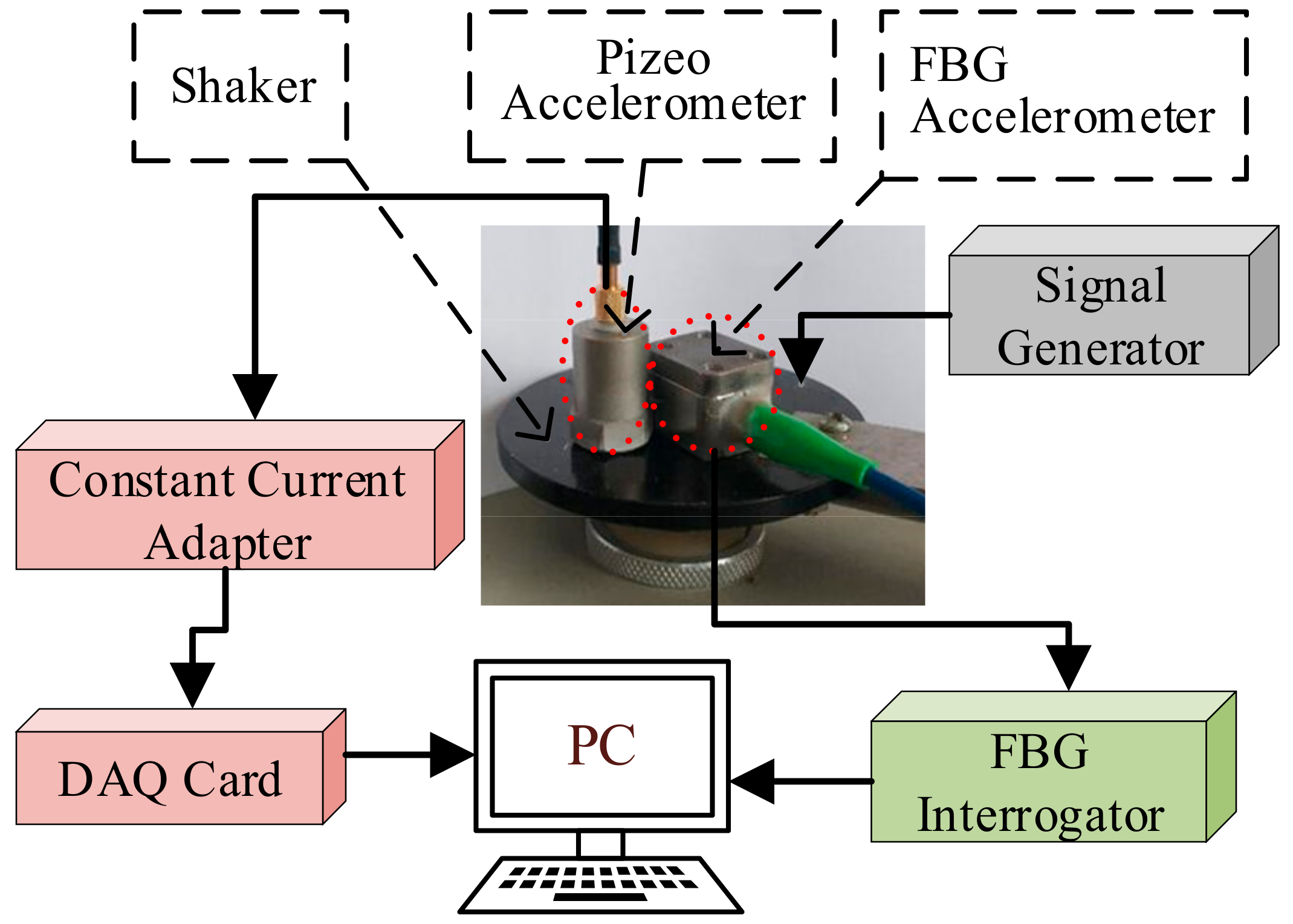
Figure 3.
Experimental results.

Figure 4.
Crest-to-trough sensitivity at 5 Hz.
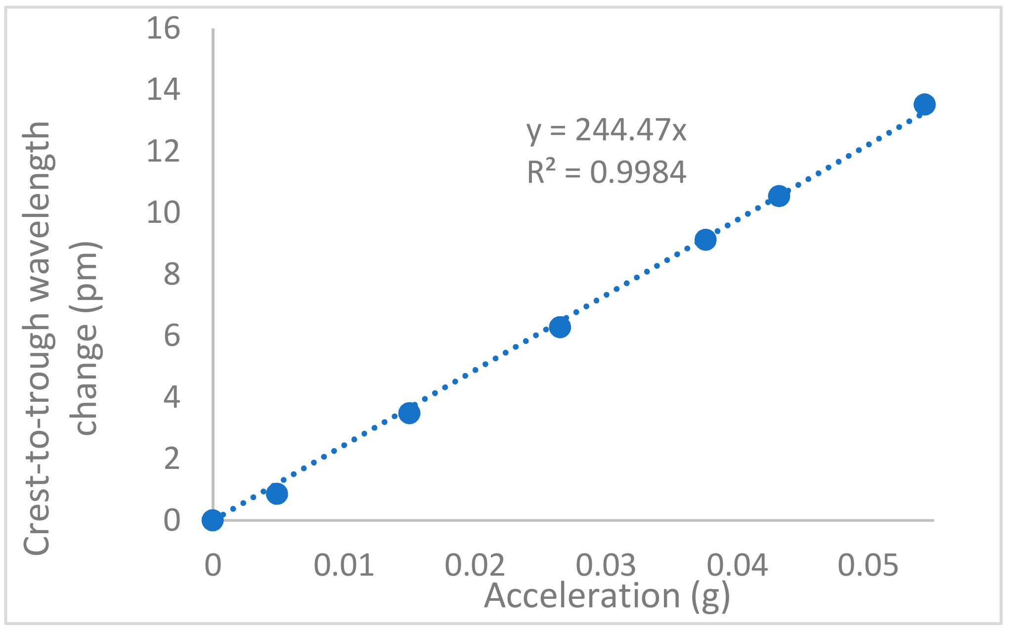
Figure 5.
Frequency response.


Table 1.
Comparison of FBG accelerometers using the optical fiber to hold the inertial object.
| Length of the Vibration Arm (mm) | Mass of the Inertial Object (gram) | Crest-to-Trough Sensitivity (pm/g) | Resonant Frequency (Hz) | Vibration Direction of the Inertial Object (Axial: Along the Fiber; Transverse: Perpendicular to the Fiber) | Ref. |
|---|---|---|---|---|---|
| 7 | 4.41 | 244 | 90 | transvers | here |
| 24 | 3 | 770 | 41 | transvers | Ref. [15] |
| 30 | 1.29 | 16 | 1300 | axial | Ref. [14] |
| 40 | 4.8 | 1.7 | 3600 | axial | Ref. [12] |
| 47 | 1.76 | 23 | 900 | axial | Ref. [13] |
| 47 | 1.76 | 545 | 34 | transvers | Ref. [13] |
| 50 | 5.71 | 1290 | 26 | transvers | Ref. [15] |
© 2019 by the authors. Licensee MDPI, Basel, Switzerland. This article is an open access article distributed under the terms and conditions of the Creative Commons Attribution (CC BY) license (http://creativecommons.org/licenses/by/4.0/).
Share and Cite
MDPI and ACS Style
Li, K.; Liu, G.; Li, Y.; Yang, J.; Ma, W. Ultra-Small Fiber Bragg Grating Accelerometer. Appl. Sci. 2019, 9, 2707. https://doi.org/10.3390/app9132707
AMA Style
Li K, Liu G, Li Y, Yang J, Ma W. Ultra-Small Fiber Bragg Grating Accelerometer. Applied Sciences. 2019; 9(13):2707. https://doi.org/10.3390/app9132707
Chicago/Turabian StyleLi, Kuo, Guoyong Liu, Yuqing Li, Jun Yang, and Wenlong Ma. 2019. "Ultra-Small Fiber Bragg Grating Accelerometer" Applied Sciences 9, no. 13: 2707. https://doi.org/10.3390/app9132707
Note that from the first issue of 2016, this journal uses article numbers instead of page numbers. See further details here.