Article

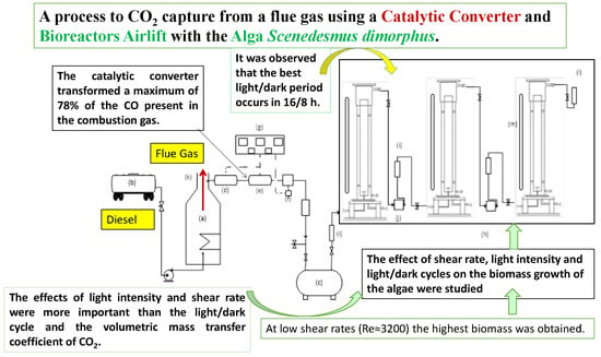
CO2 Capture of the Gas Emission, Using a Catalytic Converter and Airlift Bioreactors with the Microalga Scenedesmus dimorphus

by
Citlalli Adelaida Arroyo
1,
José Luis Contreras
1,*,
Beatriz Zeifert
2 and
Clementina Ramírez C.
1
1
Departamento de Energía, Universidad Autónoma Metropolitana-Azcapotzalco, CBI, Av. Sn. Pablo 180, Mexico City, C.P. 02200, Mexico
2
Instituto Politécnico Nacional, ESIQIE, UPALP, Zacatenco, Ciudad de Mexico C.P. 02200, Mexico
*
Author to whom correspondence should be addressed.
Appl. Sci. 2019, 9(16), 3212; https://doi.org/10.3390/app9163212
Submission received: 1 June 2019 / Revised: 27 July 2019 / Accepted: 31 July 2019 / Published: 7 August 2019
(This article belongs to the Special Issue Recent Advances in CO2 sequestrations)

Abstract

:
A process composed by a catalytic converter and three sequential Airlift photobioreactors containing the microalga Scenedesmus dimorphus was studied to capture CO2, NOx, and CO from emissions of a steam boiler which was burning diesel. The catalytic converter transformed to CO2 a maximum of 78% of the CO present in the combustion gas. The effects of shear rate, light intensity, and light/dark cycles on the biomass growth of the algae were studied. It was observed that at low shear rates (Re ≈ 3200), a high productivity of 0.29 gcel L−1 d−1 was obtained. When the microalga was exposed to 60.75 µmol·m−2·s−1 of intensity of light and a light/dark cycle of 16/8 h, a maximum productivity of 0.44 gcel L−1 d−1 and a maximum CO2 fixation rate 0.8 g CO2 L−1·d−1 were obtained. The maximum CO2 removal efficiency was 64.3%, and KLa for CO2 and O2 were 1.2 h−1 and 3.71 h−1 respectively.

Graphical Abstract

1. Introduction

Electricity generation in Mexico has proven to be a significant source of air pollution at the national level [1]. In 2015, the electricity sector produced 124.85 million of tons of CO2, 205,787 tons of NOx and 60,968 tons of CO [2,3]. In general, steam boilers produce pollutant gases such as CO, NO, NO2, hydrocarbons, SO2, and solid particles or soot. Given the need to regulate the emissions of these gases, there is a wide variety of post-combustion treatments among which are the chemical absorption and biological fixation processes using microalgae [4,5,6].
One of the limitations for the use of CO and NO emissions in the cultivation of microalgae is its low solubility of 0.0068 and 0.0026 g·L−1, respectively [7]. That is why they must first be transformed into more soluble compounds, such as CO2 and NO2 (0.0386 mol·L−1·atm−1 and more than 1 mol·L−1 in water respectively). The CO and NO can be burned catalytically to CO2 and NO2, using a catalytic converter with noble metals or metal oxides as catalysts. These converters are composed of ceramic materials in the form of a honeycomb coated with alumina where metals like platinum are supported as active sites and other oxides such as CeO2, TiO2, ZrO2, SiO2-Al2O3 [8]. These converters can use the thermic energy of combustion gases to carry out the oxidation reactions [9].
Emissions from steam generators also contain volatile organic compounds (VOCs) such as polycyclic aromatic hydrocarbons, carcinogenic aldehydes or carbon in the form of soot. The conversion of unburned hydrocarbons to CO2 is also carried out by the catalysts mentioned above. The presence of sulfur compounds such as SO2 may also be present and depends on the quality of the fuel. In general, the diesel currently sold in Mexico City does not contain significant amounts of sulfur (< 1 vol.%), so it did not represent a problem in this study. To remove the soot formed by unburnt carbon particles, zeolite-based filters with Pt are used to retain and convert the particles to CO2 [8]. Sequentially, it is necessary to place a catalytic converter for the treatment of diesel combustion emissions. In our previous study, we have observed that the removal of NO2 can be carried out in microalgae bioreactors as part of its metabolism; however, this was not the case for SO2 since this gas decreases its growth at a concentration of 60 ppm [10].
As is known, there are two types of bioreactors for cultivating algae to sequester CO2 that include open raceway ponds and closed bioreactors [11,12]. The closed bioreactors allow better control of the operating conditions such as hydrodynamics, the sterilization process, and increase of the fixation efficiency.
Among the closed bioreactors, there are the bubble columns (BC) and Airlift reactors (ALR), which consist of an inner tube (or riser) where the gas emission is bubbled at its base and an outer tube that surrounds the inner tube (or downcomer), where a flow of liquid or culture medium together with the gas flow forming a circular flow pattern avoiding the need for mechanical agitation, which decreases the energy requirements [13]. It is known that the ALR have shown better mixing, better heat transfer and mass than the BC, due to the presence of the draft tube or riser together with the advantage of simple construction without moving parts [14,15].
It is known that all nutrients in the culture medium, the mass transfer of CO2, the intensity of the light, the gas holdup, and the circulation rate of the liquid in the ALR, have a decisive role in the growth of biomass observed. Therefore, the rate of inlet gas flow leads to gas holdup and the velocity of circulation of the liquid either in the riser or in the downcomer [16,17].
The optimal flow rate of the gas that allows an excellent gas-liquid mixture has great importance in the growth of the microalgae since it will enable to control the pH and the concentration of the CO2 and O2 in the liquid-gas interface [18].
Microalgae and cyanobacteria can consume CO2 for their growth and have the highest efficiency of conversion of CO2 to O2 and products for the synthesis of biomass [19]. The absorption of CO2 by the microalgae depends on the type and quantity of nutrients, the intensity of the light, the time of exposition of light, the temperature, the pH, the CO2 concentration, the gas to liquid flow ratio, the type of reactor, the mass transfer coefficient of CO2, and the microalgae species [20]. It has been reported that the microalgae, in general, can fix CO2 concentrations of up to 20% (v/v) [21].
The objective of this work was to propose a two-stage process: The first consists in converting the emissions of a commercial steam generator, such as CO, NO, which are very little soluble in water, into their corresponding CO2 and NO2 oxides utilizing a catalytic converter. The second stage was to use these gases to feed the microalga Scenedesmus dimorphus, which grows inside a battery of three airlift bioreactors with an internal loop with different hydrodynamics, light intensity, and light/dark cycles. This study is a proposal for the design of a process using Airlift photobioreactors for the capture of CO2, CO, and NO from emissions of steam generators

2. Materials and Methods

2.1. Materials

2.1.1. Steam Boiler

In this study, gas emissions from a commercial steam boiler (Cleaver-Brooks) were used (Figure 1). The steam boiler had a steam production of 627 Kg·h−1. The temperature of the gas emission was 150 °C in the chimney (Figure 1k), and its composition was CO2 14.1 ± 0.21% (v/v), O2 2.3 ± 0.3% (v/v), CO 171 ± 5.5 ppm, hydrocarbons 0% (v/v), NO 100 ± 0.1 ppm, and N2 83.9% (v/v). The fuel of this boiler was diesel (Figure 1b).

2.1.2. Catalytic Converter

We used a commercial catalytic converter (Magnaflow 53004) designed to convert the emissions of CO, NO, and hydrocarbons from a combustion engine that burns diesel. This converter had a cell density of 400 cell in2 and was composed of a cordierite ceramic base with a layer of alumina, CeO2, and Pt as the active material to carry out the combustion reactions. The converter had a length of about 10 cm with a diameter of 10 cm.

2.1.3. Airlift Bioreactors

In this study, three Airlift bioreactors made of Shott-Duran glass (Germany) with a capacity of 4.271 L each were employed (Figure 1b). These reactors were connected in series to a line of combustion gases coming from the storage tank (Figure 1c). The gas was bubbled into the bioreactors using air diffusers made of sintered glass (average pore diameter 0.16 mm) with a diameter of 3 cm (Figure 1b), which at the same time kept the cultures in constant agitation. We use aquarium air pumps to pass the gas from one reactor to another. The gas flow was controlled by needle valves and rotameters. The bioreactors were placed inside an isothermal acrylic sheet chamber (27 ± 1 °C) with automatic temperature control. The light was provided by fluorescent lamps of 14 W (Figure 1m). The light intensity was measured utilizing a luxometer (Steren, model HER-410). To determine the profiles of the pressure within the riser tube as a function of the length, nine pressure sensors were inserted at distances of 5 cm, which consisted of transparent plastic tubes where the water level was used as a pressure measurement (Figure 2); the pressure values are in Table S1.

2.1.4. Microorganism and Inoculum

The microalga Scenedesmus dimorphus was isolated from a lake located in Mexico City, (coordinates were: 19° 25′ 57.389″ N 99° 7′ 59.549″ W). This microalga was cultured for 12 days at 27 ± 2 °C in culture medium BG-11 [22]. Then, it was centrifuged and suspended in culture medium BG-11 without a carbon source, which was substituted by a gas mixture of air-CO2 of 2% (v/v). This gas mixture was fed to the culture for 12 days through bubbling. The culture was carried out in Erlenmeyer flasks with occasional agitation and intensity of light of 17 µmol·m2·s−1 with periods of light/dark of 14/10, 16/8 and 24/0 h. The inoculum amount was 20% (v/v) of the work volume of each reactor [23].

2.1.5. Culture Media

For the cultivation and preservation of the microalga S. dimorphus, the BG-11 medium was used in aqueous media and agar slant tubes. The BG-11 medium consisted of (mg·L−1): NaNO3, 1500; MgSO4·7H2O, 75; K2HPO4, 40; CaCl2·2H2O, 36; Na2CO3, 20; Citric acid, 6; ferric citrate ammonium, 6; disodic EDTA, 1; H3BO3, 2.86; MnCl2·4H2O, 1.81; Na2MoO4·2H2O, 0.39; ZnSO4·7H2O, 0.222; CuSO4·5H2O, 0.079; Co(NO3)2· 6H2O, 0.049 [22]. The culture medium was adjusted to pH 7.4, sterilized at 121 °C and 15 lb in2 for 15 min before adding to the bioreactors.

2.2. Methods

2.2.1. Composition of the Gas Emission

The analyses of CO2, CO, O2, hydrocarbons (HC) and SO2 was carried out in the gas emission of the steam boiler and also at the output of the airlift reactors. The analysis of CO2, CO, and O2 were carried out using a digital gas analyzer (Fyrite® InTech™, Bacharach Model P/N 0024-7341, US). The hydrocarbons were analyzed using a gas chromatograph with FID detector (Varian 3400). The NOx were analyzed using a gas analyzer Testo 340, and finally, the analysis of SO2 was made by precipitation of the SO4−2 ion with BaCl2 which generates a precipitated BaSO4 that produces turbidity in water, which can be measured spectrophotometrically at a wavelength of 420 nm [24].

2.2.2. Procedure to Convert CO, NO, and Hydrocarbons

In this study, the gas flow of the emissions was 88.34 L·min−1, and it was compressed in a special tank of 300 L (Figure 1c) at a pressure of 100 psig until the boiler was turned off. The boiler combustion gases passed through a ceramic type filter to remove the soot (Figure 1d), and subsequently, the CO, NO, and Hydrocarbons (HC) were oxidized by a catalytic converter (Figure 1e) designed to oxidize these compounds to CO2 and NO2 at 350 °C by means of a control of electrical resistance (Figure 1g) in order to achieve the highest conversion. These combustion gases were analyzed before and after the catalytic converter.

2.2.3. Characterization of the Catalytic Converter by SEM and EDS

To describe this converter, the scanning electron microscopy (SEM) and X-ray energy scattering spectrometry (EDS) were used. The study of the morphology of the catalytic converter was carried out in a microscopy JOEL model JSM 6701F. Samples of the ceramic structure of the catalytic converter were vapored with a solution of Au/Pd to make them conductors; then, these were located on a graphite tape. To carry out the chemical analysis by EDS, a dispersive energy detector was incorporated in the microscope.

2.2.4. Cultures

Eight cultures were carried out using this flue gas, where the effects of gas superficial velocity, the intensity of light, light/dark cycles on the growth of microalga S. dimorphus were evaluated. The flow rates were 0.05, 0.1, and 0.15 vvm (volume of gas per volume of liquid per minute); the light intensities studied were 27, 60.75, and 76.27 µmol·m2·s−1; and the ligth/dark cycles were 14/10, 16/8, and 24/0 h (Table 1).
The cultures were carried out in three bioreactors (Figure 1h) where the combustion gas passed through the catalytic converter. This gas was fed to the reactors continuously and in series so that the gas that left a reactor served as a feed for the next reactor and so on. The temperature was maintained at 27 ± 1 °C, and the pH was not controlled. The cultures were held for 12 days, taking a sample every 24 h. All volumetric flows were controlled by rotameters (Figure 1i), and small gas pumps (Figure 1j) were used to feed each bioreactor.
The temperature of the bioreactors was kept constant using an isothermal chamber (Figure 1g) with acrylic sheets and electrical resistances. The light was provided by a fluorescent lamp of 14Watts (Figure 1m) that was placed in front of each bioreactor.

2.2.5. Calculation of Gas Holdup (φi)

The gas Holdup is part of the fluid dynamics of airlift reactors and is defined as the volumetric fraction of the gas within the total volume of a gas-liquid dispersion [25].
φ i = V G ( V L + V G )
where the subindexes L and G indicate the liquid and gas phase (often the solid phase is minimal), and the subscript i indicates the region of the reactor in which the holdup is being considered, which can be in the raiser (r), in the downcomer (d) or the total reactor (T). In our case, the φr was calculated by the Equation (2) for the riser using the liquid height before (hi) and after the flue gas was injected (hf).
φ r = ( h f h i ) h f

2.2.6. Calculation of Superficial Liquid Velocity Ulr and Uld

The superficial liquid velocity (Ulr) can be calculated using the Equation (3), where Ar and Ad are de cross-sectional areas (m2) of the riser and the downcomer respectively [26].
U l r = 0.66   ( A d A r ) 0.78 ( U g r ) 1 / 3
Ugr is the superficial gas velocity which is calculated with the Equation (4)
U g r = Q g A r
Qg is the volumetric gas flow (m3·s−1). The value of 0.66 is for concentric tube airlift reactors [26].
For its part, the superficial velocity of the liquid in the downcomer Uld is
U l d = U l r ( A r A d )
The Reynolds numbers for the riser (Re)r and the downcomer (Re)d are calculated with Equations (6) and (7):
( R e ) r = D r U l r ρ μ
( R e ) d = D d U l d ρ μ
where Dr is the diameter of the riser, and Dd is the equivalent (annular) diameter of the dawncomer. The bubble rise velocity (Ub) can be calculated using the superficial gas velocity (Ugr) in a multiphase flow which is considered as a possible flow velocity in (m·s−1) using the Equation (5) [13].
U b = U g r φ i

2.2.7. Calculation of Shear Rate (γ)

For the determination of the shear rate (γ) from hydrodynamic principles, different mathematical models have been developed [27,28], in which the rheological properties of the fluid are included or not. In our case, we have calculated the shear rate for superficial gas velocities from 0.0018 m·s−1 (0.13 L·min−1) to 0.016 m·s−1 (1.25 L·min−1).
In the model proposed by Merchuk and Ben-Zvi [28], the rheology of the culture medium is taken into account and also the injection of power (P) that supplies the gas in terms of pressure. The dissipation of energy produced by the bubbles seems a more accurate concept for the calculation of the global shear rate per time unit γ (s−2).
γ = [ P 1   U g r   l n ( P 1 P 2 ) a b   L R 2   k ] 1 / n
where k is the viscosity of the culture (Pa·sn) for Newtonian liquids, ab is the specific interfacial area (m−1), LR is the aerated reactor height, n is the flow behavior index (n = 1 for Newtonian fluid), P1 is the pressure at the top of the reactor (atm), P2 is the pressure at the bottom of the reactor (atm). The calculation of interfacial area “ab” can be made using the Equation (10), which takes into account the liquid rheology and the gas superficial velocity [29].
a b = 0.0465 ( U g r n k ) 0.51

2.2.8. Mass Balance of CO2 in the Culture

The evolution of inorganic carbon in the liquid phase (CT), during the algae growth, can be determined by knowing the alkalinity and the pH profiles as a function of time, which are associated with photosynthetic consumption of CO2 and CO2 stripping according to the Equation (11) [30]:
d C T d t = K l a [ ( C O 2 * ) ( C O 2 ) ] F C
where KLa (h−1) is the overall volumetric mass transfer coefficient for the CO2, (CO2*) (mol·L−1) represents the saturation concentration of CO2 in the liquid phase obtained by the Henry equation, and Fc (molCO2·L−1·h−1) represents the CO2 consumption rate by the microalgae photosynthetic activity [22].
F c = P   ( 0.5139 12 ) × 44
P = Δ X Δ t
where 51.39 wt % is designated as the carbon content of microalgae dry biomass by [19]; 12 (g·mol−1) and 44 (g·mol−1) represents the molecular weights of carbon and CO2, respectively. The typical molecular formula of microalgal biomass is CO0.48H1.83N0.11P0.01 [19]. The composition in weight percent that results is C51.39O32.89H7.83, N6.59P1.3. P (gcel·L−1·d−1) is the productivity, where ΔX is the difference between the maximum biomass (Xmax) and the initial biomass (Xo) (g·L−1), and Δt is the culture time (days) [22].
In the case of calculation of (CO2*), using the Henry equation:
( C O 2 * ) = P C O 2 H C O 2
H C O 2 = e [ 11.25 395.9 T 175.9 ]
where the coefficient HCO2 (Pa·m3·mol−1) is only in function of the temperature of the culture in Kelvin degrees (K) [31].

2.3. Determination of Biomass by Optical Density

The microalga biomass was measured by optical density with a spectrophotometer (Spectronic Inst. model 21D) at 678 nm. The readings obtained were interpolated on a calibration curve relating the optical density with the dry weight of S. dimorphus. The dry weight of the microalga was measured by filtering 10 mL aliquots through Whatman filter paper No. CF/A (1.6 µm pore size). Each filter plus the microalgae sample were dried at 50 °C to constant weight because it was observed that at higher temperatures the microalga degraded showing a change of color to dark brown. It was found the relationship between optical density and biomass concentration was as follows [10]:
y = 0.5847 x + 0.0112   ( R 2 ) = 0.9995
where y refers to the biomass concentration (g·L−1), and x refers to the optical density (OD678).

2.4. Determination of Maximum Specific Growth Rate

The maximum specific growth rate (d−1) was calculated using the following equation:
μ m a x = l n   ( X 2 X 0 ) Δ t
where X2 is the maximum biomass, X0 is the initial biomass (g·L−1), and Δt is the culture time where the maximum biomass was obtained (days) [22].

2.5. Determination of CO2 Removal Efficiency

To determine de CO2 removal efficiency, the CO2 concentration was measured on the outlet gas stream of each reactor by a CO2 analyzer (Fyrite® InTech™, Bacharach Model P/N 0024-7341, US). The amount of CO2 removed was calculated using the following equation [20]:
CO 2   removal   efficiency   ( % )   = ( 1 C O 2   o u p u t C O 2   i n p u t ) × 100
where the CO2 output and input were the CO2 concentration on the gas stream of each reactor.

2.6. pH, Alkalinity, and Concentration of Dissolved Inorganic Carbon (CT)

The concentration of the alkalinity (alk) was determined by titration with HCl [24], and the pH was measured using a digital pH meter (Conductronic 20), and these determinations were used to calculate the concentration of dissolved inorganic carbon (CT) following the equations used by [32,33,34]. In this case, it was assumed that, in equilibrium the Equations (20) and (21), all chemical species represented the dissolved total inorganic carbon (CT), and the CO2 concentration in equilibrium was higher than that of H2CO3.
H 2 O H + + O H    K W = [ O H ] [ H + ] = 10 14
C O 2 + H 2 O H 2 C O 3 H C O 3 + H +    K 1 = [ H C O 3 ] [ H + ] [ C O 2 ] = 10 6.381
H C O 3 C O 3 2 + H +    K 2 = [ C O 3 2 ] [ H + ] [ H C O 3 ] = 10 10.377
The total concentration of inorganic carbon is given by:
[ C T ] = [ C O 2 ] + [ H C O 3 ] + [ C O 3 2 ]
The alkalinity for the culture is the sum of the anions present minus the concentration of the protons [H+].
[ A l k ] = [ H C O 3 ] + 2 [ C O 3 2 ] + [ O H ] [ H + ]
The total inorganic carbon in the culture can be obtained as a function of the alkalinity, the pH, and the ionization fractions (α0, α1 and α2) (Equation (24)). The concentration of [OH] is determined by calculating the concentration of [H+] in accordance with the Equations (19) and (25).
C T = [ A l k ] [ O H ] + [ H + ] ( a 1 + 2 a 2 )
[ H + ]   =   1   ×   10 pH    [ O H ] = ( 1 × 10 14 ) 1 × 10 p H
The ionization fractions (α0, α1 and α2) of each species at equilibrium can be obtained using the pH and the ionization constants K1 and K2 in accordance with:
a 0 = 1 1 + K 1 [ H + ] + K 1 K 2 [ H + ] 2
a 1 = 1 1 + [ H + ] 2 K 1 K 2 + [ H + ] K 2
a 2 = 1 1 + [ H + ] 2 K 1 K 2 + [ H + ] K 2
The concentrations of [CO2], [HCO3], and [CO32−] can be obtained using the Equations (29) to (32).
Alk = [HCO3] + 2[CO32−] = α1 (CT) + 2α2 (CT)
The [OH] and [H+] concentrations were not considered in Equation (29) because both numerical values are negligible compared to the carbonate species concentrations.
[CO2] = α0 (CT)
[HCO3] = α1 (CT)
[CO32−] = α2 (CT)

2.7. Determination of the Overall Volumetric Mass Transfer Coefficient for CO2 (KLa)

The values of KLa were obtained by integration of the Equation (11), and because the Fc depends on the biomass concentration, the mean value of KLa for each culture was calculated. Also, the KLa was determined using the dynamic method, which considers the static and dynamic properties of the liquid, such as the viscosity and the liquid superficial velocity, and is given by Equation (33) [35]:
K l a = k U g r α μ e f f β ( 1 + A d A r ) δ U L r θ
where k, α, β, δ, and θ are empirical constants. µeff is the viscosity of the liquid (Pa s), and Ad and Ar are the cross sectional area (m2) of the downcomer and riser, respectively; and Ugr and ULr are the superficial gas and liquid velocity (m·s−1) in the riser.

3. Results and Discussion

3.1. Performance of the Catalytic Converter

The average composition of the flue gases that produce the steam boiler is shown as follows: CO2 14.1 ± 0.21% (v/v), O2 2.3 ± 0.3% (v/v), CO 171 ± 5.52 ppm, NO 100 ± 0.1 ppm, HC 0% (v/v), N2 83.9% (v/v). This equipment was constantly generating steam, and no significant changes in operation were observed. After carrying out 4.5 h of operation intermittently with periods of operation of 40 min, the concentrations of the gases after passing through the converter were CO2 14.40% (v/v), O2 2.30% (v/v), CO 37 ppm, NO 10.2 ppm, HC 0% (v/v), N2 83.3% (v/v). The catalytic converter transformed 78% of the CO to CO2 and 89.8% of NO to NO2 in the flue gas. The chromatographic analysis of the emissions (Varian 3400) showed the presence of small amounts of aldehydes such as acetaldehyde and acrolein (<22 ppm) which were not observed at the output of the converter. In our experiments, the CO conversion of this catalytic converter was 78% when the converter reached a temperature of 170 °C. Carlsson and Skoglundh [36] obtained 100% of CO conversion using a fresh Pt/Al2O3 catalyst at 175 °C in the form of monolith having 400 cell/in2. The chemical composition of this catalytic converter was 1 wt.%Pt supported on a monolith usually made of cordierite. During the preparation, the washcoat slurry containing the H2PtCl6, the Al2O3, and H2O covered the 75% of the total support (0.12 g coating per cm3 of monolith catalyst).
Other authors [8] also showed the same CO light-off curves (from 120 °C to 175 °C), and the chemical composition included 0.27 wt.%Pt supported on γ-Al2O3 and small amounts of La2O3 and Pd.
The previous authors [36] used concentrations of 0.1% CO with an excess of O2 of 9%, in the absence of other gases. It was observed that in the ignition experiments, the conversion of CO follows the typical light-off curves, which occurs by forming a loop when the catalytic bed is heated and when it is cooled so that two CO conversion profiles are obtained. In the ascent of temperature, the first conversion began at 140 °C and ended at approximately 175 °C for complete conversion.
In the case of our converter, it worked for 3 months, which is why we believe that it showed a good performance, given the inherent deactivation process.

3.2. Characterization of the Catalytic Converter

Employing SEM, it was possible to observe in Figure 3a an image of a cross-section of the cordierite monolith with an increase of 25X. In Figure 3b, there was an amplification of 200X, and in Figure 3c we have an increase of 700X. In Figure 3a the well-defined honeycomb ceramic structure was observed; in Figure 3b, the wall of the monolith was observed with a small layer of alumina on its surface; in Figure 3c the alumina with a porous structure was observed. The analysis of the ceramic structure by EDS of the catalytic converter and the average composition of at least three analyses of the studied region are shown in Table 2. The active compounds are Pt, CeO2, and Al2O3.

3.3. Effect of the Hydrodynamics of the Reactor Airlift on the Microalga Growth

The effect of the flow rates of 0.05, 0.1, and 0.15 vvm on algae growth, Reynolds number (Re), superficial gas and liquid velocities (Ugr and Ulr), gas holdup in the riser (φr), global shear rate (γ) in the riser, and on the volumetric mass transfer coefficient of CO2 (KLa) was evaluated to help to explain these cultures. In these cultures, we observed that the growth rate of biomass was proportionately higher for the culture made with lower flow rate (Figure 4), in the following order
C1 > C2 ≈ C3. As shown in Table 3, as the gas flow or the superficial gas velocity in riser (Ugr) increases, the velocity of the liquid in the riser (Ulr) and the downcomer (Uld) increases. In the same way, the gas holdup φr, and the numbers of Re increased from 3121 to 9362 (Table 3), clearly in turbulent regime.
It is clear that a turbulent regime prevails (Re > 2100) within the riser. Even in the downcomer, the turbulent regime is observed at the highest flow (culture C3). With these three experiments (C1 to C3), it is found that the best growth of biomass occurs in the culture C1 and demands flow patterns with numbers of Re less than 6200 and gas holdups less than 0.0082.
The culture C1 showed the maximum biomass of 3.8 g·L−1 (Table 4) and the maximum Fc (0.53 g CO2 L−1·d−1). In these cultures, the pH was uncontrolled, but it was observed that it was maintained in a range of 6–7 after the second day of the culture. This behavior could be explained due to the CO2 equilibrium [33] and the metabolism of the microalga itself [37]. Also, it was observed that the exponential growth phase continued beyond day 12.
This behavior was probably due to better gas exploitation inside the reactor, derived from a lower CO2 stripping caused by the low fed gas flow [38]. Meanwhile, for the cultures C2 and C3 with higher flow rates of 0.1 and 0.15 vvm, the maximum biomasses were of 3.27 and 3.4 g·L−1, respectively (Table 4).
This decrease is explained because it is known that algae are sensitive to shear rates [25]. It has been mentioned that the Kolmogoroff model of isotropic turbulence [39] indicates that a severe damage can occur at relatively large values of the eddy length scale. This model contemplates a parameter of length or size of the eddy where the energy begins to be dissipated by the viscous resistance.
The increase of superficial gas and liquid velocities (Ugr and Ulr) produces an increase in the global shear rate (γ) observed at the outlet of the gas disperser (Table 3). These values of (γ) were close to the values reported by Shumpe and Deckwer [29], Zaidi et al. [40], and Nishikawa et al. [41], especially at low superficial gas velocities of 0.0018 and 0.0036 m/s (Table 5); however, at a greater superficial gas velocity (0.0054 m/s) the difference was significant (15%).
The global shear rate profile against riser length is shown in Figure 5. It can be seen that in the position of the bubbler there are the highest shear rate (at 10 cm height of the bioreactor) and as the flow of bubbles increases, the shear rate decreases until reaching an average value at a height of 20 cm along the riser tube.
As is logical, the global shear rate (γ) increases with the increase of the superficial gas velocity for the cultures in the following order: C3 > C2 > C1. This same behavior is observed with the volumetric mass transfer coefficients (KLa) for CO2 and O2 (Figure 6). This means that at higher superficial gas velocities a higher mass transfer of CO2 could be expected.
Pirouzi et al., 2014 [42], using an Airlift reactor with external loop, obtained values of KLa (O2) of 9 to 26 h−1 at different superficial gas velocities. Also, Loubiere et al., 2011 [43] used an external Airlift loop reactor, cultivating Chlamydomonas reinhardtii obtained a KLa of 14.4 h−1.
Reyna-Velarde et al., 2010 [44], employing a flat panel Airlift reactor with Spirulina sp., obtained a KLa of 31.27 h−1. Contreras et al., 1998 [45], using a concentric tube Airlift reactor with a culture of Phaeodactylum tricornutum obtained a KLa of 28.8 h−1 for a value of superficial gas velocity of 0.0018 m·s−1 and biomass of 4 g·L−1. These values of KLa (O2) were higher than our results (1.54 to 3.71 h−1). This was due mainly to the Ad/Ar relationship, since the values of Ad/Ar that they report (Ad/Ar = 1) were lower than that obtained with the geometry of our reactor (Ad/Ar = 2.38), which led to us getting lower values of KLa.
However, Kazbar et al., 2019 [46], cultivated Chlorella sp. in a flat Airlift reactor in continuous culture and determined the KLa experimentally by a de-oxigenation/re-oxigenation method [47] that consisted of removing dissolved oxygen from the liquid phase by injecting gaseous nitrogen (N2) and then monitoring the increase of O2 when switching back to air injection; their value of KLa was 1.9 h−1. These values are shown in Table 6.

3.4. Effect of the Light Intensity on the Growth of Scenedesmus dimorphus

In these experiments, the cultures C4, C5, and C6 with intensities of light of 27, 60.75, and 76.27 µmol·m−2· s−1 respectively were evaluated. These intensities were used with a constant light/dark cycle of 14/10 h. In the culture C4 at a light intensity of 27 µmol·m−2·s−1, it was observed that there was a low growth of biomass, reaching a maximum biomass value of 1.55 g·L−1 (Table 4). It was also noted that the exponential growth phase was low and extended until 12 days of cultivation (Figure 7). The Productivity and Fc were 0.09 gcel ·L−1·d−1 and 0.23 gCO2·L−1·d−1, respectively (Table 4). This behavior was probably due to the low intensity of light to which the microalga was exposed, so that, the growth was photo-limited [48].
In the culture C5 at a light intensity of 60.75 µmol·m−2·s−1, the microalga had a better growth compared to the culture carried out at 27 µmol·m−2·s−1, reaching a maximum biomass value of 1.85 g·L−1 (Table 4). Besides, the exponential phase was reduced to 9 days (Figure 7), the Productivity and Fc were 0.16 g cel·L−1·d−1 and 0.28 g CO2·L−1·d−1, respectively (Table 4). In the culture C6, the light intensity was increased to 76.27 µmol·m−2·s−1, and S. dimorphus reached a biomass of 3.25 g·L−1; the productivity and Fc were 0.25 g cel·L−1·d−1 and 0.46 g CO2·L−1·d−1, respectively. Jiang et al., 2013, [22] cultured S. dimorphus using a simulated flue gas that had 15% (v/v) of CO2 with a light intensity of 100 µmol·m−2·s−1. They obtained a maximum biomass of 2.77 g·L−1; the Productivity and Fc were 0.362 g cel·L−1·d−1 and 0.664 g CO2·L−1·d−1, respectively.

3.5. Effect of the Light/Darkness Cycle on the Growth of S. dimorphus

In these cultures, the light intensity of 60.75 µmol·m−2·s−1 remained constant, and the light/dark cycles of 14/10 (culture C6), 16/8 (culture C7), and 24/0 h (culture C8) on the growth of the microalga were evaluated.
It was observed that the biomass had a remarkable increment in the culture C7 with a cycle of 16/8 h, since the maximum value was of 4.73 g·L−1 (Table 4 and Figure 8) compared to the culture with the light/dark cycle 14/10 h (C6), which had a maximum biomass of 1.85 g·L−1 (Table 4). The productivity and the Fc in the culture C7 were 0.44 g cel·L−1·d−1 and 0.8 g CO2·L−1·d−1, respectively. In the culture C8 where the light was kept on all the time (cycle 24/0), the production of biomass was very close to the biomass of the culture C7 (4.79 g·L−1, Table 4), but the specific growth rate was lower (0.21 d−1, Table 4).
These results indicate that light of moderate intensity with a long period of time could increase the growth of biomass. Basu et al., 2013, [49] exposed the microalga S. obliquus SA1 to a light intensity of 74.2 µmol·m−2·s−1, with a light/dark cycle of 14/10 h that was fed with 13.8% CO2. They obtained 4.86 g·L−1 of biomass at 34 days of culture. Also, their Fc was of 0.225 g CO2·L−1·d−1 which was lower than our results (0.8 g CO2·L−1·d−1).
Thawechai et al., 2016 [50], conducted a study in which Nannocloropsis sp. was exposed to several light intensities combined with light/dark cycles and observed that at light intensities of 80 and 120 µmol·m−2·s−1 with light/dark cycle of 16/8 h, the biomass reached its maximum values, but when they increased the period to 24 h of continuous light, the biomass did not show any growth. This result was due to the fact that a high intensity of light was coupled with a prolonged period of light, leading to an interruption of growth and subsequent cell death.

3.6. Determination of CO2 Removal Efficiency

In this study, the CO2 removal efficiency was determined for all the eight cultures. It can be observed that the CO2 removal efficiency was higher for the cultures with the light intensity of 60.75 µmol·m−2·s−1 and the light/dark cycles of 16/8 and 24/0, where the maximum value was for the culture C7 (64.3%, Figure 9). Jiang et al., 2013 [22], cultured S. dimorphus at 100 µmol·m−2·s−1 of intensity of light, and their CO2 removal efficiency was of 1.6%, which was lower than our results.

4. Conclusions

The effects of shear rate, light intensity, and light/dark cycles on the biomass growth of the S. dimorphus algae were studied. It was observed that low shear rates (Re ≈ 3200) contribute to having a greater amount of biomass. The geometry of the reactor and the Ad/Ar relationship had an important influence on the value of the overall mass transfer coefficient (KLa) since values of Ad/Ar >1 can decrease this parameter. It was observed that the best light intensity and light/dark period were 60.75 µmol·m−2·s−1 and 16/8 h, respectively. Finally, the catalytic converter used in this study converted the 78% of CO to CO2 and 89.8% of NO to NO2 in the flue gas. This fact helped the converted CO2 and NO2 gases to be assimilated by the microalgae.

Supplementary Materials

The following are available online at https://www.mdpi.com/2076-3417/9/16/3212/s1, Table S1: Pressure along the length of riser (in Pa) for the three flow rates.

Author Contributions

Conceptualization, A.C.A. and C.J.L.; Methodology, A.C.A., C.J.L. and R.C.; Formal Analysis, A.C.A., C.J.L. and B.Z.; Investigation, A.C.A., C.J.L. and Z.B.; Resources. C.J.L.; Data Curation, A.C.A. Writing: A.C.A. and C.J.L.; Review & Editing, C.J.L.; Supervision, C.J.L.; Project Administration, C.J.L.; Funding Acquisition, C.J.L., R.C. and Z.B.

Funding

This research received no external funding.

Acknowledgments

The authors gratefully acknowledge the scholarship provided by the National Council of Science and Technology (CONACYT-México) and the technical support of the Metropolitan Autonomous University- Azcapotzalco, México. The authors also thank the Instituto Politécnico Nacinal of México for the analytical facilities given to this research.

Conflicts of Interest

The authors declare no conflict of interest.

References

  1. López, M.T.; Zuk, M.; Garibay, V.; Tzintzun, G.; Iniestra, R.; Fernández, A. Health impacts from plant emissions in Mexico. Atmos. Environ. 2005, 39, 1199–1209. [Google Scholar] [CrossRef]
  2. Ministry of the Environment and Natural Resources. National Inventory of Pollutant Emissions Criteria. 2016. Available online: https://www.gob.mx/semarnat/ documentos/documentos-del-inventario-nacional-de-emisiones (accessed on 10 June 2019).
  3. National Institute of Ecology and Climate Change. National Inventory of Gas Emissions and Greenhouse Compounds. 2018. Available online: https://www.gob.mx/inecc/acciones-yprogramas/inventario-nacional-de-emisiones-de-gases-y-compuestos-de-efecto-invernadero (accessed on 10 June 2019).
  4. Wang, B.; Li, Y.Q.; Wu, N.; Lan, C.Q. CO2 bio-mitigation using microalgae. Appl. Microb. Biotech. 2008, 79, 707–718. [Google Scholar] [CrossRef]
  5. Chiang, C.L.; Lee, C.M.; Chen, P.C. Utilization of the cyoanobacteria Anabaena sp. CH1 in biological carbon dioxide mitigation processes. Bioresour. Technol. 2011, 102, 5400–5405. [Google Scholar] [CrossRef]
  6. Kaithwas, A.; Prasad, M.; Kulshreshtha, A.; Verma, S. Industrial waste derived solid adsorbents for CO2 capture: A mini review. Chem. Eng. Res. 2012, 90, 1632–1641. [Google Scholar] [CrossRef]
  7. Perry, R.H.; Chilton, C.H. Perry’s Chemical Engineer’s Handbook, 5th ed.; McGraw-Hill Kogakusha, LTD: Tokyo, Japan, 1973; pp. 3–18. [Google Scholar]
  8. Tilman, W.; Beutel, J.C.; Dettling, D.O.; Hollobaugh, W.; Torsten, W.; Mueller-Stach, P.P. Diesel Oxidation Catalysts with CO/HC Light Off and HC Storage Function. U.S. Patent No. 20090320449A1, 31 December 2009. [Google Scholar]
  9. Heo, I.; Wiebenga, M.H.; Gaudet, J.R.; Nam, I.S.; Li, W.; Kim, C.H. Ultra low temperature CO and HC oxidation over Cu-based mixed oxides for future automotive applications. Appl. Catal. B Environm. 2014, 160–161, 365–373. [Google Scholar] [CrossRef]
  10. Arroyo Gómez, C.A. Biofixation of CO2, NO and SO2 Present in the Gases of Thermoelectric Plants Using a Microalgae. Master’s Thesis, Metropolitan Autonomous University, Azcapotzalco, Mexico, 2015. [Google Scholar]
  11. Kasiri, S.; Ulrich, A.; Prasad, V. Optimization of CO2 fixation by Chlorella kassleri cultivated in a closed raceway pohotobioreactor. Bioresour. Thechnol. 2015, 194, 144–155. [Google Scholar] [CrossRef]
  12. Razzak, S.A.; Hossain, M.M.; Lucky, R.A.; Bassi, A.S.; De Lasa, H. Integrated CO2 capture, wastewater treatment and biofuel production by microalgae culturing—A review. Renew. Sustain. Energy Rev. 2013, 27, 622–653. [Google Scholar] [CrossRef]
  13. Chisti, Y. Airlift Bioreactors; Elsevier Applied Science: New York, NY, USA, 1989. [Google Scholar]
  14. Chen, Z.; Jiang, Z.; Zhang, J.; Zhang, J. Numerical and experimental study on the CO2 gas-liquid mass transfer in flat-plate airlift photobioreactor with different baffles. Biochem. Eng. J. 2016, 106, 129–138. [Google Scholar] [CrossRef]
  15. Chisti, Y. Pneumatically agitated bioreactors in industrial and environmental bioprocessing: Hydrodynamics, hydraulics, and transport phenomena. Appl. Mech. Rev. 1998, 51, 33–112. [Google Scholar] [CrossRef]
  16. Bitog, J.P.P.; Lee, I.B.; Oh, H.M.; Hong, S.W.; Seo, I.H.; Kwon, K.S. Optimized hydrodynamic parameters for the design of photobioreactors using computational fluid dynamics and experimental validation. Biosyst. Eng. 2014, 122, 42–61. [Google Scholar] [CrossRef]
  17. Nayac, B.K.; Roy, S.; Das, D. Biohydrogen production from algal biomass (Anabaena sp. PCC7120) cultivated in airlift photobioreactor. Int. J. Hydrogen Energy. 2014, 39, 7553–7560. [Google Scholar] [CrossRef]
  18. Kumar, K.; Dasgupta, C.N.; Nayak, B.; Lindblad, P.; Das, D. Review. Development of suitable photobioreactors for CO2 sequestration addressing global warming using Green algae and cyanobacteria. Bioresour. Technol. 2011, 102, 4945–4953. [Google Scholar] [CrossRef]
  19. Chisti, Y. Biodiesel from microalgae. Biotechnol. Adv. 2007, 24, 294–306. [Google Scholar] [CrossRef]
  20. Cheng, J.; Huang, Y.; Feng, J.; Sun, J.; Zhou, J.; Cen, K. Improving CO2 fixation efficiency by optimizing Chlorella PY-ZU1 culture conditions in sequential bioreactors. Bioresour. Thechnol. 2013, 144, 321–327. [Google Scholar] [CrossRef]
  21. Chang, E.H.; Yang, S.S. Some characteristics of microalgae isolated in Taiwan for biofixation of carbon dioxide. Bot. Bull. Acad. 2003, 44, 43–52. [Google Scholar]
  22. Jiang, Y.; Zhang, W.; Wang, J.; Chen, Y.; Shen, S.; Liu, T. Utilization of simulated flue gas for cultivation of Scenedesmus dimorphus. Bioresourse Technol. 2013, 128, 359–364. [Google Scholar] [CrossRef]
  23. Olguín, E.J. International Training Course. In the Use of Microalgae for the Removal of Pollutants and for the Production of Biofuels; Xalapa: Veracruz, Mexico, 2013. [Google Scholar]
  24. American Public Health Association, American Water Works Association, Water Pollution Control Federation. Standard Methods for Examination of Water and Wastewater; American Public Health Association: Washington, DC, USA, 1992. [Google Scholar]
  25. Merchuk, J.C.; Gluz, M. Bioreactors, Air Lift Reactors; Wiley Online Library: Hoboken, NJ, USA, 2002; pp. 320–352. [Google Scholar]
  26. Chisti, M.Y.; Halard, L.B.; Moo-Young, M. Liquid circulation in airlift reactors. Chem. Eng. Sci. 1988, 43, 451–457. [Google Scholar] [CrossRef]
  27. Shi, L.K.; Riba, J.P.; Angelino, H. Estimation of effective shear rate for aerated non-Newtonian liquids in airlift bioreactor. Chem. Eng. Comm. 1990, 89, 25–35. [Google Scholar] [CrossRef]
  28. Merchuk, J.C.; Ben-Zvi, S. A novel approach to the correlation of mass transfer in bubble columns with non-Newtonian liquids. Chem. Eng. Sci. 1992, 47, 3517–3523. [Google Scholar] [CrossRef]
  29. Shumpe, A.; Deckwer, W.D. Gas holdups, specific interfacial area, and mass transfer coefficients of aerated carboxy methyl cellulose solutions in a bubble column. Ing. Eng. Chem. Process Des. Dev. 1982, 21, 706–711. [Google Scholar] [CrossRef]
  30. Valdés, F.J.; Hernández, M.R.; Catalá, L.; Marcilla, A. Estimation of CO2 stripping/CO2 microalgae consumption ratios in a bubble column photobioreactor using the analysis of the pH profiles. Application to Nannochloropsis oculata microalgae culture. Bioresour. Technol. 2012, 119, 1–6. [Google Scholar] [CrossRef]
  31. Royce, P.N.C.; Thornhill, N.F. Estimation of dissolved carbon dioxide concentrations in aerobic fermentations. AICHE J. 1991, 37, 1680–1686. [Google Scholar] [CrossRef]
  32. Brune, D.E.; Novak, J.T. The use of Carbonate Equilibrium Chemistry in Quantifying Algal Carbon Uptake Kinetics. Eur. J. Appl. Microbiol. Biotechnol. 1981, 13, 71–76. [Google Scholar] [CrossRef]
  33. Camacho, R.F.; Acién Fernández, F.G.; Sánchez Pérez, J.A.; García Camacho, F.; Molina Grima, E. Prediction of disolved Oxigen and Carbon Dioxide Concentration Profiles in Tubular Photobioreactors for Microalgal Culture. Biotechnol. Bioeng. 1999, 62, 71–86. [Google Scholar] [CrossRef]
  34. Livansky, K. Losses of CO2 in outdoor mass algal cultures: Determination of the mass transfer coefficient KL by means of measured pH course in NaHCO3 solution. Algol. Stud. 1990, 58, 87–97. [Google Scholar]
  35. Kargi, F.; Moo-Young, M. Transport Phenomena in Bioprocesses; Moo-Young, M., Ed.; Comprehensive Biotechnology, Pergamon Press: Oxford, UK, 1985; pp. 5–55. [Google Scholar]
  36. Per-Ander, C.; Skoglundh, M. Low–Temperture oxidation of carbón monoxide and methane over alumina and ceria supported platinum Catalysts. Appl. Catal. B Environ. 2011, 101, 669–675. [Google Scholar]
  37. Graham, L.E.; Y Wilcox, L.W. Algae; Prentice Hall: Upper Saddle River, NJ, USA, 2000. [Google Scholar]
  38. Contreras, E.M. Carbon dioxide stripping in bubble columns. Ind. Eng. Chem. Res. 2007, 46, 6332–6337. [Google Scholar] [CrossRef]
  39. Landau, L.D. Fluid Mechanics; Pergamon: Oxford, UK, 1975; Volume 6, pp. 115–123. [Google Scholar]
  40. Zaidi, A.; Bourziza, H.; Echihabi, L. Warmeubergang und effektives Schergefalle in Blasensaule-Bioreaktoren mit Xanthan-Losungen. Chem. Ing. Tech. 1987, 59, 748–749. [Google Scholar] [CrossRef]
  41. Nishikawa, M.; Kato, H.; Hashimoto, K. Heat transfer in aerated tower filled with non-Newtonian Liquids. Ind. Eng. Chem. Process Des. Dev. 1977, 16, 133–137. [Google Scholar] [CrossRef]
  42. Pirouzi, A.; Nosrati, M.; Shojaosadati, S.; Shakhesi, S. Improvement of mixing time, mass transfer, and power consumption in an external loop airlift photobioreactor for microalgae culures. Biochem. Eng. J. 2014, 87, 25–32. [Google Scholar] [CrossRef]
  43. Loubiere, K.; Pruvost, J.; Alour, F.; Legrand, J. Investigations in an external-loop airlift photobioreactor wih annular light chambers and swirling flow. Chem. Eng. Res. Des. 2011, 89, 164–171. [Google Scholar] [CrossRef]
  44. Reyna-Velarde, R.; Cristiani-Urbina, E.; Hernández-Melchor, D.J.; Thalasso, F.; Cañizares-Villanueva, R.O. Hydrodinamic and mass transfer characterization of a flat-panel airlift photobioreactor with high light path. Chem. Eng. Process. 2010, 49, 97–103. [Google Scholar] [CrossRef]
  45. Contreras, A.; García, F.; Molina, E.; Merchuk, J.C. Interaction between CO2-mass transfer, light availability, and hydrodynamic stress in the growth of Phaeodactylum tricornutum in a concentric tube airlift photobioreactor. Biotechnol. Bioeng. 1998, 60, 317–325. [Google Scholar] [CrossRef]
  46. Kazbar, A.; Cogne, G.; Urbain, B.; Marec, H.; Le-Gounic, B.; Tallec, J.; Takache, H.; Ismail, A.; Pruvost, J. Effect of dissolved oxygen concentration on microalgal culture in photobioreactors. Algal Res. 2019, 39, 101432. [Google Scholar] [CrossRef] [Green Version]
  47. Roustan, M. Transferts Gas-Liquide dans les Procédes de Traitement des eaux et des Effluents Gazeux [WWW Document]. Lithium Bromide. Lavoisier. 2003. Available online: https://www.lavoisier.fr/libre/enviornnement/transferts-gaz-liquide-dans-les-procedes-de-traitment-des-eaux-et-des-effluents-gazeux/roustan/descriptif-9782743006051 (accessed on 15 August 2017).
  48. Xue, S.; Su, Z.; Cong, W. Growth of Spirulina platensis enhanced under intermitent illumination. J. Biotechnol. 2011, 151, 271–277. [Google Scholar] [CrossRef]
  49. Basu, S.; Roy, A.S.; Mohanty, K.; Ghoshal, A.K. Enhanced CO2 sequestration by a novel microalga: Scenedesmus obliquus SA1 isolated from bio-diversity hotspot region of Assam, India. Bioresour. Technol. 2013, 143, 369–377. [Google Scholar] [CrossRef]
  50. Thawechai, T.; Cheirsilp, B.; Louhasakul, Y.; Boonsawang, P.; Prasertsan, P. Mitigation of carbon dioxide by oleaginous microalgae for lipids and pigments production: Effect of light illumination and carbon dioxide feeding strategies. Bioresour. Technol. 2016, 219, 139–149. [Google Scholar] [CrossRef]
Figure 1. Process of CO2 capture from gas emissions. (a) Commercial steam boiler. (b) Diesel tank. (c) Combustion gas storage tank. (d) Soot filter. (e) Catalytic converter. (f) Gas compressor. (g) Control panel. (h) Biorreactors. (i) Rotameters. (j) small gas pump. (k) boiler chimney. (l) Isotermal box and (m) Lamps.
Applsci 09 03212 g001
Figure 2. Schematic diagram of airlift reactor and its pressure sensors along the riser tube, using a sintering glass disperser.
Applsci 09 03212 g002
Figure 3. Micrograph of the monolith structure observed with magnification of 25X (a), 200X (b) and 700X (c). The corresponding EDS analysis of the monolith structure is shown in (d); the analysis on the alumina layer is in (e) and the active metals Ce and Pt in (f).
Applsci 09 03212 g003
Figure 4. Effect of the flow rate on the growth of S. dimorphus and the pH.
Applsci 09 03212 g004
Figure 5. Global shear rate in the riser tube in function of the length of the reactor for the three gas flows studied.
Applsci 09 03212 g005
Figure 6. Effect of the superficial gas velocity Ugr on the volumetric mass transfer coefficient of CO2 (KLaCO2) calculated by the balance of CO2 and KLa (O2) using the dynamic method.
Applsci 09 03212 g006
Figure 7. Effect of the light intensity on growth of S. dimorphus.
Applsci 09 03212 g007
Figure 8. Effect of the light/dark cycles on growth of S. dimorphus.
Applsci 09 03212 g008
Figure 9. CO2 removal efficiency of all cultures.
Applsci 09 03212 g009
Table 1. Experimental conditions of the cultures.
CultureLight Intensity (μmol·m−2·s−1)Light/Dark Cycle (h)Gas Flow (vvm)
C176.2712/120.05
C276.2712/120.10
C376.2712/120.15
C42714/100.1
C560.7514/100.1
C676.2714/100.1
C760.7516/80.1
C860.7524/00.1
Table 2. Chemical analysis of the catalytic converter by EDS for the monolithic structure and the active film.
Chemical ElementIn the Monolith Structure (wt.%)In the Supported Active Phase (wt.%)
O250.0441.26
Mg7.325.45
Al17.7318.59
Si24.9115.18
Ce016.2
Pt03.33
Table 3. Effect of the superficial gas velocity Ugr on the hydrodynamic parameters in each of the airlift bioreactors.
CultureQg (L·min−1)Ugr (m·s−1)Ulr (m·s−1)Uld (m·s−1)Ub (m·s−1)φrRerRed(γ) (1/s)
C10.1370.00180.000780.000320.3670.004931219028.07
C20.2750.00360.00150.000650.4390.0082624118059.42
C30.4120.00540.002340.000980.3370.0169362270810.5
Table 4. Productivity P, CO2 Fixation rate Fc and μmax of the cultures.
CultureBiomass (g·L−1)μmax (d−1)P (gcel L−1·d−1)Fc (gCO2 L−1 ·h−1)
C13.80.220.290.53
C23.270.190.270.49
C33.40.130.220.41
C41.550.150.090.23
C51.850.220.160.28
C63.250.290.250.46
C74.730.240.440.80
C84.790.210.370.69
Table 5. Comparison of global shear rates γ in [1/s] from other authors respect the values we obtained in cultures C1, C2, and C3 as a function of Ugr.
CultureUgr (m·s−1)Shumpe [29]Zaidi et al. [40] Nishikawa et al. [41] Present Work
C10.00186588
C20.003688149.4
C30.00541212.520.810.5
Table 6. Comparison of volumetric mass coefficients among different Airlift configurations.
Airlift ReactorKLa (h−1)Ref.
External loop (inclined)9 to 26[42]
External loop14.4[43]
Flat panel31.27[44]
Concentric tube28.8[45]
Concentric tube1.54 to 3.71Present work
Flat panel1.9[46]

