Failure Probability Prediction of Thermally Stable Diamond Composite Tipped Picks in the Cutting Cycle of Underground Roadway Development


CSIRO Mineral Resources, PO Box 883, Kenmore, QLD 4069, Australia
*
Author to whom correspondence should be addressed.
Appl. Sci. 2019, 9(16), 3294; https://doi.org/10.3390/app9163294
Submission received: 17 July 2019
/
Revised: 3 August 2019
/
Accepted: 6 August 2019
/
Published: 11 August 2019
(This article belongs to the Special Issue Fatigue and Fracture of Non-metallic Materials and Structures)
Abstract
:Featured Application
Pick failure risk assessment in mining and civil industries.
Abstract
The Thermally Stable Diamond Composite (TSDC) tipped pick has been developed to replace Tungsten Carbide (WC) tipped picks for hard rock cutting. Due to the material properties of TSDC, a major failure mode of TSDC tipped picks during rock cutting is random failures caused by excessive bending force acting on the cutting tips. A probabilistic approach has been proposed to estimate the failure probability of picks with this failure mode. However, there are two limitations in existing research: only one drum revolution is considered, and the variation of rock thickness is ignored. This study aims to extend the current approach via removing these limitations, based on the failure probability analysis of picks over a full cutting cycle in the underground coal mining roadway development process. The research results show that both drum advance direction and the variation of rock thickness have significant impacts on pick failure probability. The extended approach can be used to estimate pick failure probability for more realistic scenarios in real applications with improved accuracy. Although the study focused on TSDC tipped picks, the developed approach can also be applied to other types of picks.
1. Introduction
The Thermally Stable Diamond Composite (TSDC) material is made using ceramic-based silicon to bind synthetic diamond grains together [1,2]. Research on TSDC’s properties and its applications can be found in [3,4,5,6,7,8]. In brief, as a type of diamond composite, the wear resistance of TSDC is several hundred times better than Tungsten Carbide (WC) [7,8]. Due to the use of silicon as the binder, the mechanical properties of TSDC remain stable at temperatures up to 1200 °C [2]. The thermal stability of TSDC is much higher than that of ordinary polycrystalline diamond (PCD), which employs metallic cobalt as the binding material [2]. PCD is generally suitable for operational temperature below 750 °C [9]. Higher thermal stability is critical for hard rock cutting tools because research has revealed that the temperature at the contact area between cutting tip and rock surface can reach as high as 1100 °C [10]. High wear resistance and high thermal stability make TSDC a potentially superior material for hard and abrasive rock cutting. One type of TSDC tipped picks, namely SMART*CUT picks, have been specifically developed to tackle the challenge of high abrasiveness and high temperature observed in hard rock cutting [3,4,5].
Picks are a type of rock cutting tool which are broadly equipped on excavation machines such as continuous miners and roadheaders to break rock in the mining and construction industries. Understanding the performance and reliability of picks is important for industries to increase production efficiency, improve production safety and reduce production cost [11,12]. Many efforts including laboratory experiments and field trials have been made to study picks from various aspects [3,4,5,6,7,8,9,10,11,12,13,14,15,16,17,18,19,20,21,22,23,24]. An important aspect of these studies is pick force analysis [4,5,12,13,14,15,16,17,18,19]. During the course of rock cutting, a pick is generally subjected to three orthogonal forces—cutting force, normal force and lateral force [13]. These forces can be affected by various factors including depth of cut (DOC) [5,12,13,14,15], rock strength [13,14,15] and attack angle [5]. Another important aspect of pick performance study is failure analysis [11,12,17,20,21,22,24,25], including identification of typical pick failure modes [17], investigation of the causes of high consumption of picks [12], protection of pick body by use of a cap tip [12,20] and understanding of the body bending failures of picks [21].
Although existing studies largely focused on WC tipped picks, studies with a focus on the performance and failure characteristics of TSDC tipped picks have also been carried out (see [3,4,5,6,11,25]). These studies showed that while TSDC tips were able to cut hard rock with a uniaxial compressive strength of 260 MPa [24], they were less capable to bear bending and impact forces than WC tips due to their lower toughness [5]. Failures caused by excessive impact or bending forces were a major concern for TSDC tipped picks [11]. Therefore, it is important to predict the failure risk of TSDC tipped picks which are subjected to excessive bending or impact forces in real industrial applications. As indicated above, the forces acting on a pick are affected by multiple factors during the rock cutting process. Some of these factors often have considerable uncertainties (i.e., their values vary randomly within a considerable range) in the real world. For example, there are often uncertainties in rock properties and machine operations during the mining production process. Due to these uncertainties, the forces acting on a pick consequently change randomly during the production process. Additionally, the material properties of TSDC cutting tips often have significant random variations [25]. In addition, the geometry of TSDC cutting tips with the same design may also vary considerably. As a result, the sudden failures of TSDC tips caused by excessive bending force or impact force during normal production often occur in a random manner.
Currently, a probabilistic approach has been developed to assess the failure risk of picks with random sudden failures based on underground coal mine roadway development with a case study on the TSDC tipped picks in [11]. Note that although the approach proposed in [11] was developed based on the scenario of underground roadway development in the coal mining industry, it is a general approach and can be applied to other rock cutting scenarios. This approach consists of three steps: firstly, the continuous rock cutting process of a pick over one drum revolution is discretized into a series of small segments; secondly, the failure probability of a pick for cutting each of these segments is estimated; and finally the failure probability of the pick over the whole cutting process is estimated. In [11], the influences of multiple major factors including pick tip geometry, Brazilian Tensile Strength (BTS) of pick tip, the attack angle of the pick, DOC and rock BTS on the failure probability of picks were modelled. Later on, a reliability-based-approach (RBP) [6] was developed to link the failure probability of pick tips subject to sudden bending failures for cutting a segment of rock to the length of the rock segment, so that the pick failure probability estimation accuracy can be improved.
This study aims to improve the usefulness of existing approach via removing two critical limitations in existing models. The first limitation is that only one drum revolution was considered in the modelling process. The second limitation is that the variation of rock thickness is ignored. However, in the actual production process, the drum advance distance is generally much larger than the drum’s advance distance in one revolution. For example, in underground coal mine roadway development, the sump-in depth is typically about the half of the drum’s cutting diameter which is the advance distance of the drum over multiple revolutions. Over the sump-in stage, the drum often involves cutting the roadway roof with different rock thickness. Therefore, to make the failure analysis approach more applicable to the real-world scenario, these two limitations should be removed.
To address the above issue, the existing approach will be extended to take into account a more realistic rock cutting production process. Given that there are various rock cutting production processes utilized in industry, the extended approach will be developed based on the scenario of an underground coal mine roadway development using continuous miners with TSDC tipped picks, in order to remain consistent with [11]. However, the extended approach will also be applicable to other rock cutting scenarios and other types of picks.
Development of an underground roadway normally consists of many cutting cycles. A cutting cycle is the process in which a continuous miner implements a full face cut (an example is given in the next section). Extension of the analysis approach to a full cutting cycle in mining production could face a number of challenges, e.g., determination of the drum revolutions and the thickness of hard rock cut in each revolution. However, the extension of the approach from one cutting cycle to multiple cutting cycles will be relatively straightforward. Therefore, this paper focuses on the extension of the approach to a full cutting cycle. More realistic scenarios, the corresponding challenges and solutions will be discussed. A case study on the failure probability assessment of TSDC tipped picks in a full cutting cycle will be presented to demonstrate the application of the extended approach.
2. Extended Pick Failure Probability Assessment Approach
2.1. A Typical Cutting Cycle
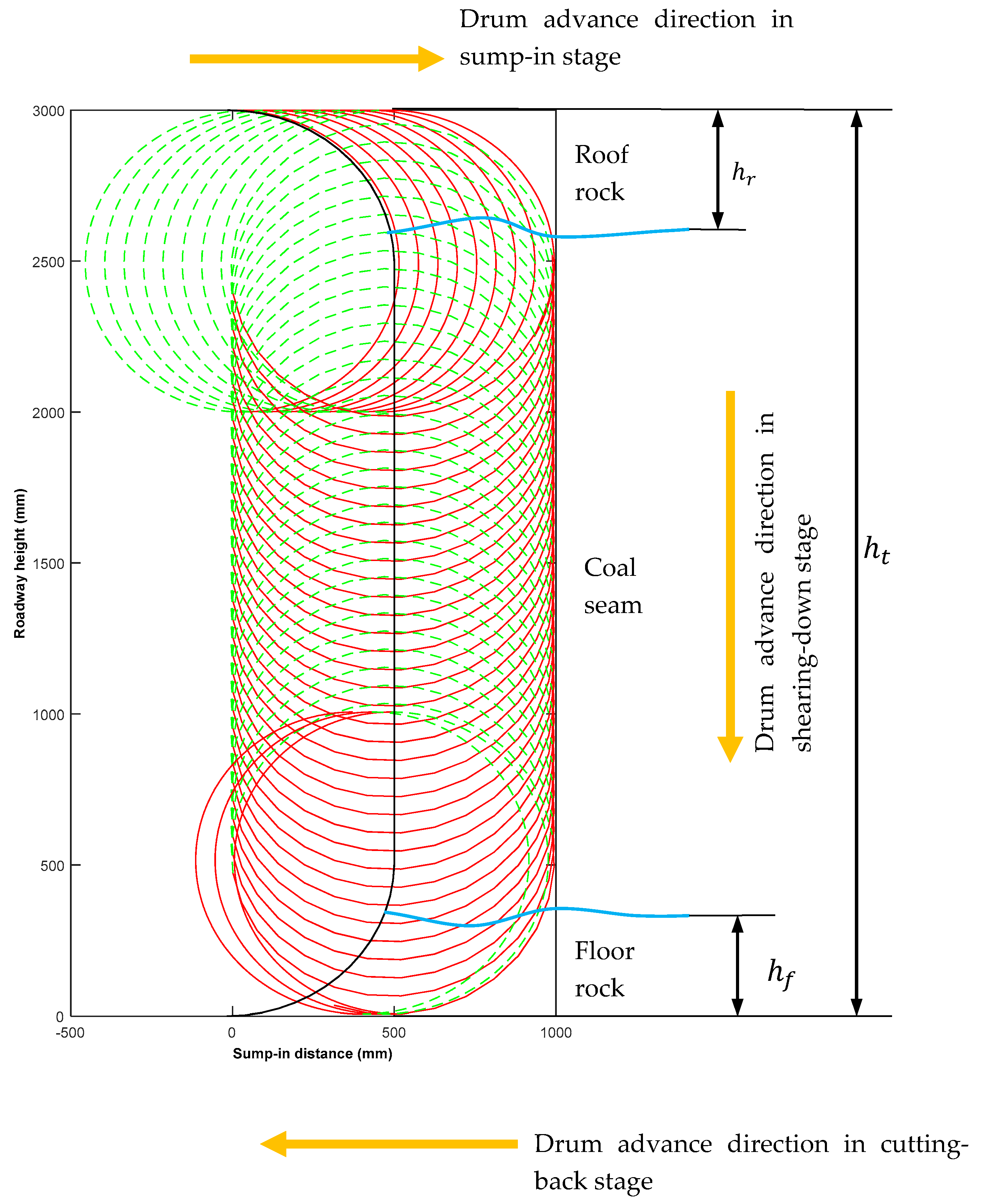
Figure 1 shows a schematic view of a typical cutting cycle in underground roadway development with a continuous miner. As an example, Figure 2 shows the locus of a pick tip on the cutting drum of a continuous miner over such a cutting cycle.
A drum is normally equipped with a large number of picks which are attached to the drum on the external surface. The reason that only a pick is shown in Figure 1 is to make the figure clear.
The roadway face can be divided into three sections: the roof rock, the floor rock and the coal seam. The cases where coal exists inside a rock section or rock bands are included inside the coal seam are not considered in this study. A ‘full cutting cycle’ is the complete process for cutting these three sections sequentially. In this cycle, the drum first cuts into the face along the roof for a half of the drum to form the roof, then shears down to the floor, and finally cuts back to clear the floor. Therefore, a full cutting cycle can be divided into three stages: sump-in (cutting-into), shearing-down and cutting-back.
In Figure 2, , and are respectively the height of the roadway, the thickness of the rock removed to form the roadway roof (roof rock) and the thickness of the rock removed to form the roadway floor (floor rock). The thickness of the roof rock and that of the floor rock are measured from the roadway roof and the roadway floor respectively. The parameters used to develop Figure 2 are shown in Table 1.
Other information used to draw Figure 2 is as follows:
A full cutting cycle involves multiple drum revolutions which are depicted by the locus of a pick tip in Figure 2. In order to show the drum advance directions more clearly, the locus of the pick tip in one drum revolution is divided into two equal parts: the half involving rock/coal cutting is marked in red and the other half is marked in green. The black line represents the face profile before this cutting cycle. The two blue curves respectively indicate the interface between the roof rock and the coal seam, and that between the coal seam and the floor rock. At the beginning of the face cutting cycle, i.e., the initial position, the circle formed by the cutting tips of the drum just touches the face profile before this cutting cycle and the pick tip in consideration is located at the top most position, which is the start point to measure the angular position of the pick in the sump-in stage.
The aim of this study is to estimate the failure probability of a pick over a full cutting cycle. The pick failures in the following analysis have the same meaning as those defined in [11], that is, the sudden failure of the tip and/or body of a pick due to excessive bending or impact force acting on the pick tip. Other failure modes such as tip fatigue failure will be studied in the future. In this study, it is assumed that rock breakout is effective. When a pick is installed on a drum, it is randomly selected from a given batch of picks. Once being installed on the drum, the pick will be in service continuously until it has failed.
From [11], it is known that the failure of a pick is a combination of its tip failure and body failure. As the failure probability analysis approach of body failures is the same as that of tip failures and it is assumed that the tip failures are independent of body failures, the following analysis mainly focuses on the pick tip failure probability estimation. In addition, as the failure probability of a pick tip over a cutting cycle consisting of three stages is a combination of its failure probability over these three stages, the pick tip failure probability over each individual stage will be estimated initially.
2.2. Pick Tip Failure Probability during the Sump-in Stage
In the sump-in stage, the drum normally cuts into the face along the roof for a sump-in depth of about the cutting radius (i.e., the half of the tip-to-tip diameter) of the drum. To implement the required sump-in depth, the drum needs to rotate multiple revolutions. The pick tip failure probability in this stage is a combination of the tip failure probability over individual drum revolutions. If the roof rock thickness is less than the tip-to-tip diameter of the drum (which is quite common during real production), the drum will partially cut roof hard rock and partially cut the coal seam over a single revolution. As the coal is generally much softer and weaker than the rock, the pick failure probability due to cutting coal can be ignored [11].
To estimate the pick tip failure probability over each drum revolution, the thickness of the roof rock in each individual drum revolution needs to be determined. In reality, the roof rock thickness generally fluctuates randomly, and it is normally difficult to obtain the distribution of roof rock thickness. For simplicity, instead of using a continuous distribution, the roof rock thickness can be approximated by several mean values with their corresponding occurrence likelihoods in industrial applications. In this case, based on the total probability theorem, the failure probability of a pick tip with a given allowable bending force in a drum revolution can be estimated by
where is the pick tip failure probability at the -th drum revolution in the sump-in stage; is the number of mean roof rock thickness values in consideration; is the pick tip failure probability at the -th drum revolution in the sump-in stage when the mean roof rock thickness is (mm) and tip allowable bending force is ; and is the likelihood (%) that the mean roof rock thickness is . Obviously,
The pick failure probability can be estimated using the models given in [11].
Nevertheless, when using the models given in [11], one needs to consider the following points:
The first issue is the determination of the cutting sector of the drum, (degree) (see Figure 3). In [11], since the impact of cutting soft coal is ignored, the cutting sector indicates the hard rock cutting sector and is given by
where, is the hard rock cutting sector of the drum (in degrees) when the mean roof rock thickness is (mm). is the tip-to-tip diameter of the drum (mm).
However, determination of the cutting sector in this way would be inconvenient when multiple drum revolutions are involved, because of the uncertainty of the rock thickness in each individual drum revolution. To resolve this problem, the cutting sector of a drum in one revolution is defined as the central angle of the drum engaging coal and/or rock cutting. With this definition, the cutting sector is between 90 degrees and 180 degrees in the sump-in stage (see Figure 3). The cutting sector of the drum at the -th revolution can be obtained by solving the following equation:
where, is the cutting sector of the drum at the -th revolution (in degrees), is the drum rotational speed (rpm), and is the drum advance speed (m/min).
As the hard rock cutting sector can be calculated using Equation (3) and the failure probability for cutting coal is ignored, the cutting sector in the sump-in stage can be set to 180 degrees in the calculation if the roof rock thickness is not greater than .
In shearing-down stage, the cutting sector is 90 degrees when the distance between the center of the drum and the floor is not less than . The estimation of the cutting sector when the distance between the center of the drum and the floor is shorter than will be discussed in the next section. Obviously, the hard rock cutting sector for a given revolution cannot be greater than the full cutting sector of this revolution.
The second issue for consideration is the calculation of the DOC of the pick at the first revolution. According to [11,18], the maximum DOC (nominal DOC) can be calculated by
where is the number of starts of the drum and is the drum advance distance per revolution (mm/r):
As the cutting starts from the initial position on the first revolution, the maximum DOC of the pick in consideration in this revolution is only a quarter of that in other revolutions because the pick rotates only a quarter of a revolution to reach the maximum advance distance in this revolution (see Figure 2 and Figure 3). For example, with the parameters in Figure 2 and the number of the starts being 2, the maximum DOC of this pick in the first revolution is only 7.5 mm, while it is 30 mm in the other revolutions.
The final point is the estimation of the pick tip failure probability of the last revolution. On this revolution, the pick may not complete a full cut of the roof rock before the drum moves to shearing-down stage. However, as the drum will continue cutting when its cutting mode changes from sump-in to shearing-down, and the variations of the DOC during the transition period can be ignored, the calculation of the pick failure probability of the last revolution can be treated as the same as that in the other revolutions (see Figure 2).
Once the failure probability of the pick tip in each drum revolution in the sump-in stage has been estimated, its failure probability in the sump-in stage, , is
where is the number of drum revolutions for implementing the sump-in cutting process, which is given by
In Equation (8), is the sump-in distance (mm).
In reality, the sump-in depth cannot be accurately controlled due to limitations of the equipment control systems, resulting in the number of the drum revolutions for sump-in cutting fluctuating randomly. This issue will be studied in due course. In this paper, only fixed sump-in depth is considered.
2.3. Pick Failure Probability during the Shearing-Down Stage
When the operation of the drum shifts from the sump-in stage to the shearing-down stage, its advance direction changes from horizontal (along the roof) to vertical (towards the floor). In the shearing-down stage, the drum primarily cuts the coal seam, as well as some floor rock (Figure 2). This stage may also involve cutting roof rock if the thickness of the roof rock is greater than the cutting radius of the drum (Figure 2). However, the roof rock thickness is generally less than two thirds of the tip-to-tip diameter of the drum, and the coal is much softer than the rock. Therefore, in the following analysis, the impact of cutting roof rock and the coal seam on the pick tip failure probability in the shearing-down stage is ignored, and only the impact of cutting the floor rock on the pick tip failure probability is considered. The scenario where the roof rock thickness can take any value will be studied in due course.
Three issues need to be addressed in the analysis of the pick tip failure probability during the shearing-down stage. The first issue is that although the location of the pick at the drum transition point from the sump-in stage to the shearing-down stage can be calculated, it is not convenient to use this location to count the drum revolutions. To address this, the following simplification is possible if the roof rock thickness is less than the 2/3 of the tip-to-tip diameter of the drum. As the rock cutting in the last cycle at the sump-in stage has been fully considered, it is acceptable to assume that the first revolution in the shearing-down stage always starts from the point with the maximum sump-in distance (rightmost point) at the last revolution in the sump-in stage.
The second issue is that similarly to the roof rock, the thickness of the floor rock also generally varies from place to place. As a result, both the number of the drum revolutions involving floor hard rock cutting and the rock length cut in each drum revolution can be uncertain (i.e., their values can change randomly). However, this process is different from the sump-in stage. To solve this problem, the calculation of the pick tip failure probability always starts from the first drum revolution in the shearing-down stage, because
In Equation (9), is the largest mean thickness of the floor rock (mm), is the pick tip failure probability over the -th drum revolution in the shearing-down stage, is the height of the roadway (mm), and is the number of revolutions from the 1st drum revolution to the -th drum revolution in the shearing-down stage.
Equation (9) holds because the drum will not start to cut the floor rock until the -th drum revolution satisfies the following condition:
The third issue is that the thickness of the floor rock can vary over a drum revolution in the shearing-down stage, and thus it is required to identify whether a segment being cut is rock or not. Figure 4 shows an arbitrary segment (the -th segment) in the shearing-down stage. It can be seen from this figure that a segment being cut is rock only when its distance from the floor is shorter than and its angular position (central angle) is less than the cutting sector. Note that, unlike in the sump-in stage where the angular position of a segment is measured from vertical, the angular position of a segment in the shearing-down stage is the angle between the horizontal direction and the line to the middle point of the segment. The cutting sector in the shearing-stage is also measured from the horizontal direction.
As previously mentioned, the cutting sectors of the revolutions in the shearing-down stage are not all the same. If the distance between the centre of the drum and the floor is not less than the drum’s tip-to-tip diameter, the cutting sector of the drum in a revolution is 90 degrees; otherwise, the cutting sector will be greater than 90 degrees. From Figure 4, it can be found that the drum in the last revolution has the largest cutting sector. As the thickness and the length of any segment are very small compared with the drum’s cutting radius, the influence of the segment on the cutting sector can be ignored. As such, triangle is an equilateral triangle. This means that the cutting sector in the last revolution is 120 degrees. In other words, the end angle of the cutting sector in the last revolution in the shearing-down stage, , is
The end angles of cutting sectors in other revolutions in the shearing-down stage will be between 90 degrees and 120 degrees. However, accurate calculation of the cutting sector in an arbitrary drum revolution is not further discussed as it is not the focus of this study. For this paper, the cutting sector in the -th revolution, , is approximated to be
where
Given these constraints, the pick tip failure probability over the shearing-down stage can be estimated using a similar approach for calculating the pick tip failure probability over the sump-in stage, with a consideration of the differences between these two stages. The first difference in the tip failure probability calculation is the segment rock condition. In the sump-in stage, if the -th segment in the -th revolution is not rock, then any -th ( > ) segment in the same revolution will not be rock; while in the shearing-down stage, any segments within the drum’s cutting sector in a drum revolution may or may not be rock. However, once a segment in a drum revolution is rock, all segments at the same angular position in the following drum revolutions will also be rock. The second difference is the rock cutting start angle. While the start angle of rock cutting sector in the sump-in stage is generally equal to zero, the start angle of rock cutting sector in the shearing-down stage is often non-zero (see Figure 4). As the DOC is normally much smaller than the drum’s tip-to-tip diameter, the start angle of rock cutting sector in the shearing-down stage, , can be estimated by
where is the Heaviside step function, and
As is a random variable, both and are also random variables. If , the drum will not cut the floor rock.
Due to the above-mentioned differences between the sump-in stage and the shearing-down stage, there are some variations in the approach to estimating the failure probability of pick tips in the shearing-down stage. In the sump-in stage, the pick tip failure probability for each individual drum revolution is estimated first, and then the pick tip failure probability over the whole stage is estimated. However, this approach is not suitable for handling the segment rock conditions in the shearing-down stage. To address this issue, the pick tip failure probability for cutting the -th segments in all the revolutions in the shearing-down stage will be estimated first, and then the pick tip failure probability over the whole shearing-down stage is estimated.
With a consideration of the variation of rock thickness, the pick tip failure probability for cutting the -th segments in all the revolutions over the shearing-down stage is given by
where is the failure probability of the pick tip for cutting the -th segments in all the revolutions in the shearing-down stage, is the number of mean floor rock thickness values in consideration, is the pick tip failure probability for cutting the -th segment in the -th drum revolution in the shearing-down stage when the mean floor rock thickness is (mm), is the likelihood (%) that the mean floor rock thickness is (mm), and is the number of drum revolutions in the shearing-down stage:
Then, the failure probability of the pick tip over the shearing-down stage, , is
where is the number of segments in a revolution in the shearing-down stage:
In Equation (19), is the central angle of a segment in the shearing-down stage (in this study, all drum revolutions are equally segmented).
From Equations (16) and (18), it can be seen that to estimate the failure probability of the pick tip in the shearing-down stage, must be calculated first. To calculate , it is necessary to determine whether an individual segment in the shearing-down stage is hard rock. To address this issue, the mid-point method [26] applied in [11] is applied again. If the midpoint of a segment is within the floor hard rock, the whole segment is regarded as the same hard rock. Based on this concept, the pick tip failure probability for cutting the -th segment in the -th drum revolution with the rock thickness of is given by
where, is the probability that actual bending force is greater than the allowable bending force of the pick tip, and is the angular position of the -th segment in the -th drum revolution (degree).
In Equation (20), is the distance of the -th segment in the -th drum revolution from the roadway floor:
The computation based on Equations (20) and (21) can often be simplified, because in the real world, the chord of a drum engaging in rock cutting cannot exceed its tip-to-tip diameter which is usually about 1000 mm. The rock thickness normally does not change dramatically over this short distance. In this case, it is reasonable to assume that once drum starts to cut rock in a revolution, it will continue to cut the rock over the rest of its cutting sector in the same revolution. This means that although rock thickness changes randomly, its mean value over a drum revolution remains constant. Then the failure probability of the pick tip for cutting the -th segment in the -th drum revolution with the rock thickness of can be estimated using the following equation:
Correspondingly, the pick tip failure probability over the shearing-down stage can be estimated using the following equation to replace Equations (16) and (18):
2.4. Pick Tip Failure Probability during the Cutting-Back Stage and over the Full Cutting Cycle
The methods for analyzing the failure probability of the pick tip over the last stage in a cutting cycle and the accumulation of the failure probability of the pick tip over the full cutting cycle are presented in this section. The pick failure probability over the full cutting cycle is also analyzed in this section.
2.4.1. Pick Tip Failure Probability over the Cutting-Back Stage
The analysis method used for the pick tip failure probability over the sump-in stage can be adopted for analyzing the pick tip failure probability over the cutting-back stage. However, from Figure 2, it can be seen that the amount of hard rock cutting involved in this stage is tiny, the bending force from the cutting process is generally smaller than the allowance bending force of the pick tips. As a result, it can be assumed that
where, is the failure probability of the pick tip over the cutting-back stage.
2.4.2. Pick Tip Failure Probability over the Full Cutting Cycle
Once the pick tip failure probabilities over all three stages in a cutting cycle have been obtained, the tip’s failure probability of the given pick over the full cutting cycle, , can be estimated by
For an arbitrarily selected pick, its cutting tip’s failure probability over the full cutting cycle is given by
where is the probability density function of the allowable forces of the pick tips.
2.4.3. Pick Failure Probability over the Full Cutting Cycle
As indicated previously, the failure of a pick is the combination of its tip failure and its body failure. The pick body failure probability over a cutting cycle can also be estimated using the same approach for estimating the pick tip failure probability. If the body failure probability of a pick over the abovementioned full cutting cycle is , and the body failure of the pick is independent of its tip failure, then failure probability of the pick over the full cutting cycle, is
In the application of Equation (25) or Equation (26), it should be noted that the three stages occur sequentially. To take the sequence of the stages into account, it is better to introduce a variable of time. This is discussed in the next section.
2.5. Change of the Pick Failure Probability over Time
The failure probability prediction models given in the above sections show the relationship between the pick failure probability and drum revolutions. It may be desired to understand the change of the pick failure probability over time during mining production. This can be done by linking the revolution to time in the above models. As all revolutions are equally segmented, the relationship between the pick failure probability and time can be expressed using the following piece-wise function:
In Equation (28), is the pick failure probability over time , is the pick failure probability for cutting the first segment, and is the pick failure probability for sequentially cutting segments starting from the first. This calculation needs to consider the cutting stages and the variation of rock thickness and can be done by using the models developed in the previous sections. Parameter is the time required for a pick to cut one segment (sec) which is given by
where is the central angle of a segment (in degrees).
3. A Case Study
A case study is presented in this section to demonstrate the application of the extended approach. The relevant parameters and values in the case study shown in [11] were adopted in this case study. Detailed conditions of this case study are as follows:
It is assumed that a continuous miner was used to develop a roadway in an underground coal mine. The roadway consists of three sections as shown in Figure 2. The total height of the roadway was 3000 mm. The roof rock and the floor rock were both sandstone with the same material properties as shown in Table 1 in [11].
The continuous miner was equipped with a 2-start drum which has a tip-to-tip diameter of 1000 mm. The rotational speed and the advance speed of the drum were respectively 50 rpm and 2.35 m/min. In a full face cutting cycle, the drum first cut into the roof of the roadway with a sump-in depth of 500 mm, then sheared down 2000 mm, and finally cut back for 150 mm. The rock breakout during all the cutting processes was effective. According to Equations (8) and (17), it can be calculated that the number of drum revolutions for the sump-in of 500 mm is 11 and for the shearing-down of 2000 mm it is 44.
A full set of TSDC tipped picks were installed on the drum. These picks were identical to those TSDC tipped picks studied in [11]. The bottom diameter of the tips was 12 mm, and the arm length for the bending force acting on the tips was 4.6 mm. The attack and tilt angles of the picks in consideration were 55 degrees and 0 (zero) degree respectively. Each pick cuts one line.
In addition, the following assumptions which are made in the case study in [11] are also adopted in this case study:
- Only sudden failures caused by excessive bending force are considered;
- Tip failure of a pick is independent of its body failure;
- Each small segment covers a central angle of 10 degrees.
Given that the influences of drum operating parameters, pick geometry, and the material properties of pick and rock have been analyzed in [11], and rock variations and drum advance directions are two new factors introduced in this extended approach, this study focused on the investigation of the influences of these two new factors on the pick failure probability. To this end, only average TSDC tips with the mean allowable force of 9.745 kN were analysed. Furthermore, a series of what-if analyses were carried out based on the following three scenarios:
Scenario 1: The thickness of the roof rock can be represented by two mean values, (410 mm, 460 mm), with their corresponding likelihoods of (35%, 65%). The thickness of the floor rock can be represented by three mean values, (450 mm, 500 mm, 610 mm), with their corresponding likelihoods of (25%, 50%, 25%).
Scenario 2: The thickness of the roof rock and the floor rock can be represented by the same set of two mean values, (410 mm, 460 mm), with their corresponding likelihoods of (35%, 65%).
Scenario 3: The thickness of the roof rock and the floor rock can be represented by a single value of 442.5 mm (=410 × 35% + 460 × 65%), which is the expected value of the random variable “rock thickness” in Scenario 2.
3.1. Results
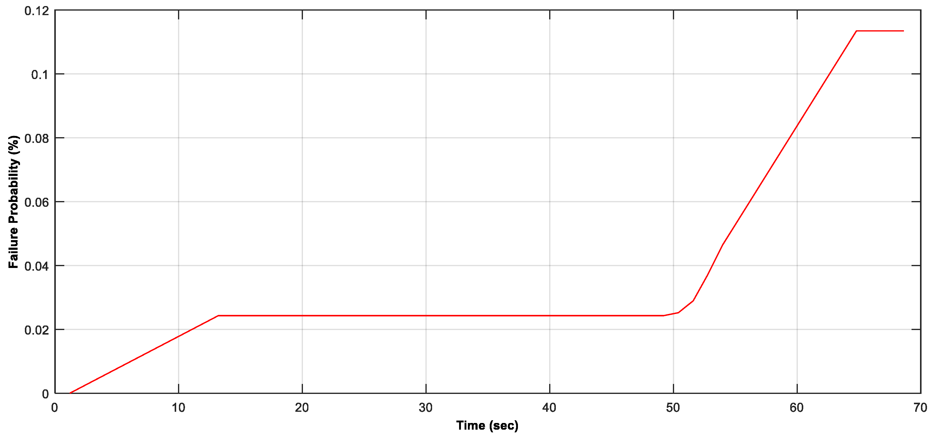
Figure 5 shows the pick tip failure probability changing with cutting time in a cutting cycle for Scenario 1.
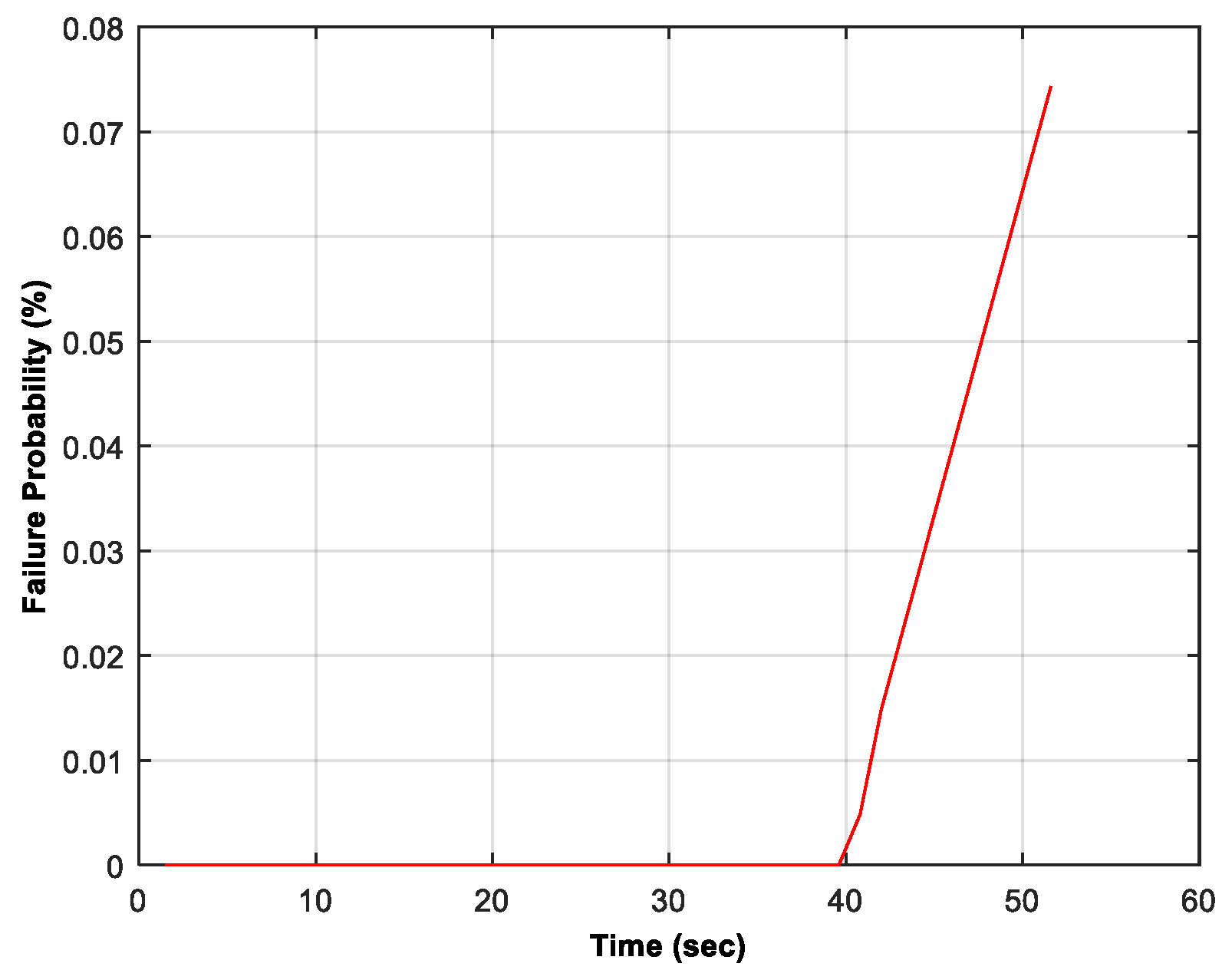
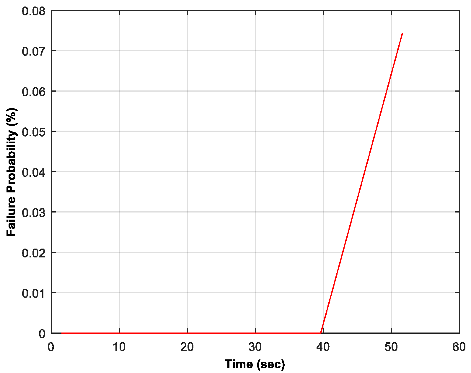
Figure 6 and Figure 7 illustrate the pick tip failure probabilities over the sump-in stage and the shearing-down stage for Scenario 2, respectively. As the tip failure probability in the cutting-back stage is regarded to be zero, the cutting back stage is no longer considered in the analysis for Scenarios 2 and 3.
3.2. Discussion
Figure 5 shows that in a cutting cycle, the pick tip failure probability changes over time in a style of constant–increasing–constant–increasing–constant. The first constant period (zero period) occurs in the sump-in stage and lasts about 1.2 s, mainly due to the small DOC in the first revolution as mentioned in Section 2.2. In the first revolution, the maximum DOC is only 5.875 mm. The bending force generated from cutting the given sandstone with this small DOC will not damage the tips in the consideration. The first increase period happens in the sump-in stage due to hard rock cutting. The second constant period and the second increase period both occur in the shearing-down stage. In this stage, the tip cuts the coal seam first and then cuts hard floor rock. When cutting the coal seam only, the tip has a failure probability of 0 (zero) because as assumed, tips will not be subjected to bending-caused failure when they are cutting coal. As a result, the tip failure probability over the coal cutting period remains constant. Once the pick involves floor rock cutting, its tip failure probability increases over time again. The third constant period corresponds to the cutting-back stage. As discussed in Section 2.4.1, the failure probability of the tip at this stage can be ignored (i.e., it is regarded to be zero).
A comparison between Figure 6 and Figure 8 indicates that the variation in the rock thickness can significantly affect the pick tip failure probability in the sump-in stage. Although the rock thickness in Scenario 3 is the expected value of the rock thickness in Scenario 2, the tip failure probability over the sump-in stage in Scenario 2 is much higher than that in Scenario 3. The reason is that there is 65% chance for the roof rock mean thickness to be 460 mm, which is much higher than the expected value of 442.5 mm. As all the rock thickness values are less than the drum’s cutting radius (500 mm), a larger value of rock thickness means that the pick needs to cut rock segments with larger DOC. According to the formula given by Goktan [14] and Equation (20) in [11], the bending force acting on the tip is proportional to the square of DOC, and therefore a larger DOC will result in a higher failure probability of tips.
However, a comparison between Figure 7 and Figure 9 shows that the variation in the rock thickness has little influence on the pick tip failure probability in the shearing-down stage. The reason for this phenomenon is that the drum advance direction in the sharing-down stage is perpendicular to that in the sump-in stage. When the drum advances towards the floor rock, an increase in the floor rock thickness will change the number of drum revolutions involving hard rock cutting, rather than the DOC of rock segments being cut. The changed number of drum revolutions involving hard rock cutting will also change the tip failure probability, but the magnitude of the change in the tip failure probability heavily depends on the ratio of the rock thickness variation to the average rock thickness. In the above examples, the variation of the maximum rock thickness in Scenario 2 (460 mm) to the expected mean rock thickness in Scenario 3 (442.5 mm), and that of the minimum rock thickness in Scenario 2 (410 mm) to the expected mean rock thickness in Scenario 3 are respectively 17.5 mm and −32.5 mm. As the absolute values of the variations are both less than the drum’s advance distance per revolution (47 mm), the difference between drum revolutions involving hard rock cutting in Scenario 2 and Scenario 3 is less than 1 (one) revolution. This small change in the number of the drum revolutions involving hard rock cutting has a trivial influence on the tip failure probability, because the ratios of the variations of the maximum and the minimum rock thickness to the expected value are small (3.95% and −7.34% respectively). As a result, the pick tip failure probabilities over the shearing-down stage in both scenarios are nearly the same.
The influences of the drum advance direction on the pick tip failure probability can be further explored by comparing Figure 7 with Figure 6 and comparing Figure 9 with Figure 8. From Figure 6 and Figure 7, it can be found that the tip failure probability in the shearing-down stage is much higher than that in the sump-in stage although the rock thickness distribution in both stages are the same. This finding is also evidenced by the comparison between Figure 8 and Figure 9. In Scenario 3, the rock removed in the sump-in stage is slightly more than that in the shearing stage, but the tip failure probability over the sump-in stage is 1.6 × 10⁻⁴%, much lower than the tip failure probability over the shearing-down stage which is 0.07433%. A major cause for this failure probability difference is the different maximum DOC due to the different drum advance directions in these two stages. In the shearing-down stage, the drum advance direction is perpendicular to the floor. If the drum involves rock cutting in a revolution, it will often cut the rock with the maximum DOC. By contrast, in the sump-in stage, the drum advances along the roof. When the rock thickness is less than the drum’s cutting radius, the DOC of the rock cut by the drum will be less than the maximum DOC. As abovementioned, a small change in DOC can result in a large variation in pick tip failure probability.
From the above analysis, it is noted that the prediction accuracy of the bending force on pick tip directly affects the accuracy of pick tip failure probability estimation. Currently, the bending force was analyzed based on the formula given by Goktan [14] and laboratory rock cutting tests [11]. However, laboratory rock cutting tests are often costly and time-consuming. Additionally, measuring forces on individual picks in situ is difficult. Therefore, new methods such as inverse analysis [27,28] may be needed to help force prediction.
4. Conclusions
In this paper, an extended probabilistic approach is proposed to remove the following two critical limitations in existing research on the estimation of the probability of pick random failures due to excessive bending force on pick cutting tips:
- Only one drum revolution is considered;
- The variation of rock thickness is ignored.
As such, this extended approach can be used to estimate the pick failure probability for a cutting process which consists of multiple drum revolutions and involves different rock thickness.
The research results show that drum advance direction can dramatically influence pick tip failure probability. Pick tip failure probability when the drum advances along the rock panel (like cutting a roadway roof in the sump-in stage) is lower than that when the drum advances towards the rock panel (like cutting the floor rock in the shearing-down stage), if rock thickness is less than the drum’s cutting radius. The variation of rock thickness can also impact the pick tip failure probability, but this influence depends upon drum advance direction, the rock mean thickness, and the relative variation of the rock thickness to its mean value. In general, the influence of the variation in rock thickness on the pick tip failure probability when the drum advances along the rock panel is much greater than that when the drum advances towards the rock panel.
This extended approach is developed based on the failure probability analysis of picks over a full cutting cycle in the underground roadway development of coal mine. Nevertheless, it can be extended to other rock cutting applications straightforwardly. The research results can be used to optimize the design and operation of cutting drums with both TSDC picks and other type of picks to increase productivity and reduce production costs.
However, in the current approach, it is assumed that the roof rock thickness is less than two thirds of the drum’s tip-to-tip diameter, the sump-in depth is constant, and failures are independent of each other. Further studies are needed to address these issues.
Author Contributions
Y.S. conceptualized the study and developed the original methodology. X.L. and H.G. contributed to the improvement of the analysis. Y.S. wrote the original draft of the manuscript. X.L., H.G. and Y.S. reviewed and improved the manuscript.
Funding
This research received no external funding.
Acknowledgments
The research was sponsored by the Commonwealth Scientific and Industrial Research Organization (CSIRO).
Conflicts of Interest
The authors declare no conflict of interest.
References
- Mlungwane, K.; Herrmann, M.; Sigalas, I. The low-pressure infiltration of diamond by silicon to form diamond–silicon carbide composites. J. Eur. Ceram. Soc. 2008, 28, 321–326. [Google Scholar] [CrossRef]
- Boland, J.N.; Li, X.S. Microstructural characterisation and wear behaviour of diamond composite materials. Materials 2010, 3, 1390–1419. [Google Scholar] [CrossRef]
- Li, X.S.; Sun, Y. Development of hard rock cutting tool with advanced diamond composites. Adv. Mater. Res. 2013, 690–693, 1831–1835. [Google Scholar] [CrossRef]
- Shao, W.; Li, X.S.; Sun, Y.; Huang, H. Laboratory comparison of SMART*CUT picks with WC picks. Adv. Mater. Res. 2014, 1017, 323–328. [Google Scholar] [CrossRef]
- Shao, W.; Li, X.S.; Sun, Y.; Huang, H. Parametric study of rock cutting with SMART*CUT picks. Tunn. Undergr. Space Technol. 2017, 61, 134–144. [Google Scholar] [CrossRef]
- Sun, Y.; Li, X.S. Failure probability of thermally stable diamond composite tips for cutting rock segments. Mater. Sci. Forum 2018, 936, 192–197. [Google Scholar] [CrossRef]
- Li, X.S.; Boland, J.N. The wear characteristics of superhard composite materials in abrasive cutting operations. Wear 2005, 259, 1128–1136. [Google Scholar] [CrossRef]
- Li, X.S.; Boland, J.N.; Guo, H. A comparison of wear and cutting performance between diamond composite and tungsten carbide tools. Ind. Diam. Rev. 2008, 68, 51–54. [Google Scholar]
- Vogt, D. A review of rock cutting for underground mining: Past, present and future. J. S. Afr. Inst. Min. Metall. 2016, 116, 1011–1026. [Google Scholar] [CrossRef]
- Shao, W.; Li, X.S.; Sun, Y.; Huang, H.; Tang, J.Y. An experimental study of temperature at the tip of point-attack pick during rock cutting process. Int. J. Rock Mech. Min. Sci. 2018, 107, 39–47. [Google Scholar] [CrossRef]
- Sun, Y.; Li, X.S. A probabilistic approach for assessing failure risk of cutting tools in underground excavation. Tunn. Undergr. Space Technol. 2017, 70, 299–308. [Google Scholar] [CrossRef]
- Prokopenko, S.; Li, A.; Kurzina, I.; Sushko, A. Improved operating performance of mining machine picks. IOP Conf. Ser. Mater. Sci. Eng. 2016, 142, 1–8. [Google Scholar] [CrossRef]
- Evans, I. A theory of the cutting force for point-attack picks. Int. J. Min. Eng. 1984, 2, 63–71. [Google Scholar] [CrossRef]
- Goktan, R. A suggested improvement on Evan’s cutting theory for conical bits. In Proceedings of the Fourth International Symposium on Mine Mechanization and Automation, Brisbane, Australia, 6–9 July 1997; Gurgenci, H., Hood, M., Eds.; Cooperative Research Centre for Mining Technology and Equipment: Kenmore, Australia, 1997; Volume I, pp. 57–61. [Google Scholar]
- Nishimatsu, Y. The mechanics of rock cutting. Int. J. Rock Mech. Min. Sci. 1972, 9, 261–270. [Google Scholar] [CrossRef]
- Goktan, R.M.; Gunes, N. A semi-empirical approach to cutting force prediction for point-attack picks. J. S. Afr. Inst. Min. Metall. 2005, 105, 257–263. [Google Scholar]
- Sun, Y.; Li, X.S. Ineffective rock breaking and its impacts on pick failures. In Proceedings of the 31st International Symposium on Automation and Robotics in Construction and Mining, Sydney, Australia, 9–11 July 2014; Ha, Q., Shen, X.S., Akbarnezhad, A., Eds.; University of Technology, Sydney: Sydney, Australia, 2014; pp. 754–760. [Google Scholar]
- Hekimoglu, O.Z.; Fowell, R.J. Theoretical and practical aspects of circumferential pick spacing on boom tunnelling machine cutting heads. Min. Sci. Technol. 1991, 13, 257–270. [Google Scholar] [CrossRef]
- Sun, Y.; Li, X.S. Slant angle and its influence on rock cutting performance. Adv. Civ. Eng. 2018, 2018, 1–11. [Google Scholar] [CrossRef]
- McNider, T.; Grygiel, E.; Haynes, J. Reducing frictional ignitions and improving bit life through novel pick and drum design. In Proceedings of the 3rd Mine Ventilation Symposium, University Park, State College, PA, USA, 12–14 October 1987; Mutmansky, J.M., Ed.; Society of Mining Engineers: Littleton, CO, USA, 1987; pp. 119–125. [Google Scholar]
- Sun, Y.; Li, X.S. Experimental investigation of pick body bending failure. Int. J. Mech. Eng. Robot. Res. 2018, 7, 184–188. [Google Scholar] [CrossRef]
- Hurt, K.G.; MacAndrew, K.M. Cutting efficiency and life of rock-cutting picks. Min. Sci. Technol. 1985, 2, 139–151. [Google Scholar] [CrossRef]
- Sun, Y.; Li, X.S. Comparison of the methods for calculating instant depth of cut. Adv. Mater. Res. 2013, 634–638, 3313–13320. [Google Scholar] [CrossRef]
- Li, X.S.; Tiryaki, B.; Cleary, P.W. Hard rock cutting with SMART/CUT technology. In Proceedings of the 22nd World Mining Congress and Expo, Istanbul, Turkey, 11–16 September 2011; Eskikaya, S., Ed.; Aydoğdu Ofset: Ankara, Turkey, 2011; pp. 725–732. [Google Scholar]
- Sun, Y.; Li, X.S. Modelling the property variation of diamond composite and its impact on the reliability of cutting tools. Adv. Mater. Res. 2012, 565, 448–453. [Google Scholar] [CrossRef]
- Vu, K.A.T.; Stewart, M.S. Predicting the likelihood and extent of reinforced concrete corrosion-induced cracking. J. Struct. Eng. 2005, 131, 1681–1689. [Google Scholar] [CrossRef]
- Ning, J.; Liang, S.Y. Model-driven determination of Johnson-Cook material constants using temperature and force measurements. Int. J. Adv. Manu. Tech. 2018, 97, 1053–1060. [Google Scholar] [CrossRef]
- Ning, J.; Liang, S.Y. Inverse identification of Johnson-Cook material constants based on modified chip formation model and iterative gradient search using temperature and force measurements. Int. J. Adv. Manu. Tech. 2019, 102, 2865–2876. [Google Scholar] [CrossRef]
Figure 1.
A schematic view of a typical cutting cycle in underground roadway development.

Figure 2.
Locus of a typical pick tip in a typical cutting cycle in underground roadway development.
Figure 2.
Locus of a typical pick tip in a typical cutting cycle in underground roadway development.

Figure 3.
Cutting sector in sump-in stage.

Figure 4.
A segment in the shearing-down stage.

Figure 5.
Thermally Stable Diamond Composite (TSDC) tip failure probability over a cutting cycle–Scenario 1.
Figure 5.
Thermally Stable Diamond Composite (TSDC) tip failure probability over a cutting cycle–Scenario 1.

Figure 6.
TSDC tip failure probability in the sump-in stage–Scenario 2.

Figure 7.
TSDC tip failure probability in the shearing-down stage–Scenario 2.

Figure 8.
TSDC tip failure probability in the sump-in stage–Scenario 3.

Figure 9.
TSDC tip failure probability in the shearing-down stage–Scenario 3.


Table 1.
Parameters used to draw Figure 2.
Table 1.
Parameters used to draw Figure 2.
| Parameter | Unit | Value |
|---|---|---|
| Roadway height | mm | 3000 |
| Drum’s tip-to-tip diameter | mm | 1000 |
| Drum rotational speed | rpm | 50 |
| Drum advance speed | m/min | 3 |
| Drum sump-in depth | mm | 500 |
| Drum cutting-back distance | mm | 150 |
© 2019 by the authors. Licensee MDPI, Basel, Switzerland. This article is an open access article distributed under the terms and conditions of the Creative Commons Attribution (CC BY) license (http://creativecommons.org/licenses/by/4.0/).
Share and Cite
MDPI and ACS Style
Sun, Y.; Li, X.; Guo, H. Failure Probability Prediction of Thermally Stable Diamond Composite Tipped Picks in the Cutting Cycle of Underground Roadway Development. Appl. Sci. 2019, 9, 3294. https://doi.org/10.3390/app9163294
AMA Style
Sun Y, Li X, Guo H. Failure Probability Prediction of Thermally Stable Diamond Composite Tipped Picks in the Cutting Cycle of Underground Roadway Development. Applied Sciences. 2019; 9(16):3294. https://doi.org/10.3390/app9163294
Chicago/Turabian StyleSun, Yong, Xingsheng Li, and Hua Guo. 2019. "Failure Probability Prediction of Thermally Stable Diamond Composite Tipped Picks in the Cutting Cycle of Underground Roadway Development" Applied Sciences 9, no. 16: 3294. https://doi.org/10.3390/app9163294
Note that from the first issue of 2016, this journal uses article numbers instead of page numbers. See further details here.