1. Introduction
The number of cardiovascular disease (CVD) deaths has increased by 41% from 1990 to 2013 [
1]. A better understanding of CVD pathogenesis, aetiology, and haemodynamic behaviours may help to improve cardiovascular interventions and therapeutic procedures. Various in vivo measurements, in vitro measurements, and numerical modelling have provided a better insight into the vascular system and haemodynamics [
2,
3,
4,
5]. However, in vivo measurements may not provide high precision. For instance, transcranial Doppler sonography is a common non-invasive measurement method but it has limited spatial resolution [
6]. In addition, the induced signal from slow-moving organs is not detectable in ultrasound techniques [
7]. Computational fluid dynamics (CFD) have been extensively used for haemodynamic modelling [
8,
9,
10]. However, most of these studies need experimental validation to be reliable for clinical use and can lack complex fluid–wall interaction. Therefore, in vitro modelling can be used to investigate the haemodynamics and optimise catheter-based vascular interventions. Particle image velocimetry (PIV) of forced flow in silicone arterial phantoms has been frequently used for in vitro modelling of haemodynamics.
Several experimental modelling investigations have been performed in rigid silicone phantoms [
11,
12,
13,
14]. However, some studies that utilised fluid–structure interaction (FSI) reported that rigid wall assumptions can lead to overestimation of wall shear stress (WSS) in comparison with a compliant phantom [
15,
16,
17,
18]. In addition, wall stiffness is a measure of arterial health, and the pulse waveform differs in stiff and compliant arteries [
19]. Failing to mimic arterial compliance reduces the precision of the model [
20].
Compliance is the ability of the artery to dilate and recoil due to the changes in transmural pressure. Compliance is an important factor in pulsatile flow haemodynamics. Hence, matching compliance across the in vitro phantom and in vivo artery is important to obtain meaningful haemodynamics during experimentation. Since wall thickness is inversely proportional to compliance, the fabrication of the phantom must yield accurate and precise wall thickness to enable successful experimental results. Although the wall thickness varies in different arterial regions, significant thickness variation in compliant phantoms can cause unphysiological compliance distribution and unrealistic flow fields [
21]. Such problems reduce the clinical value of experimental outcomes.
Different manufacturing methods have been used for the construction of compliant phantoms [
22,
23,
24,
25,
26]. Dip coating of a rapid prototyped mould has been a common casting method for compliant phantom construction [
27,
28]. In this method, the mould is dipped and coated several times in a silicone bath until the desired thickness is achieved. However, it is difficult to ensure consistent wall thickness. Yip et al. [
29] fabricated a compliant model of the aortic arch using dip coating. A wall thickness of 6.35 mm (1/4”) was developed. This is considerably larger than the wall thickness required for in vivo compliance matching [
24,
30]. Arcaute and Wicker [
31] constructed different compliant phantoms using dip spin coating. The 3D printed mould was spun on a two-axis mechanism subsequent to each coating step. They determined that horizontal dipping produced more uniform thickness compared with vertical dipping. Their results showed 0.60 mm and 0.58 mm of vertical and horizontal thickness bias respectively, for different diameter locations. Büsen et al. [
32] fabricated a compliant phantom of the aortic arch including the superior branches for in vitro PIV analysis. A hollow patient specific mould was designed, and 3D printed. The inner surface of the mould was coated with RT620 elastomer and rotated to ensure even distribution of the mixture. A 1.5 mm wall thickness was reported with a ±0.5 mm tolerance. In another study the effect of different cannula positions on interventricular haemodynamics was measured using PIV in idealized transparent models of the left ventricle. The models were fabricated from platinum-cured silicone rubber with a 0.7 mm wall thickness. However, the authors did not report the manufacturing process, or the wall thickness tolerance [
33]. Early work by Friedman et al. [
34] manufactured a compliant model of the artery for haemodynamic measurement. A segment of the artery obtained from autopsy was pressurized and used as a mould. Silastic E RTV elastomer was injected into the mould and cured. The mould was removed by cutting the artery. However, the authors did not report the wall thickness precision.
Ionita et al. [
35] directly fabricated compliant phantoms using Polyjet 3D printers and TangoPlus FullCure
® (Objet Ltd., Rehovot, Israel) material without the need for casting. Despite the high accuracy of the phantom, this material is semi-transparent and was not useful for PIV studies. However, advancements in polymers and resins may allow direct printing of high accuracy phantoms in the future. Another method which has been used for compliant phantom fabrication is a lost-core casting method. In this method, a male mould is placed centrally in a female mould. Then, the gap in between is filled with silicone and once cured the male mould is dissolved or mechanically removed. Geoghegan et al. [
24] fabricated a compliant model of the carotid artery using the lost-core casting method. The comparison of the phantom with the initial stereolithographic (STL) file showed 3%–5% cross-sectional area error. Similarly, Sulaiman et al. [
36] fabricated a one-to-one compliant model of the aortic arch. Comparison with the original STL file for the internal dimension of the phantom showed less than 0.52 mm variance in geometry at four positions on the male mould. They reported a 2 mm uniform wall thickness but no declaration of wall thickness variation. However, this wall thickness is also potentially larger than appropriate [
37]. Marconi et al. [
38] used 3D printed moulds to fabricate an aortic compliant phantom. A drawback of the method was that the hollow inner mould was removed mechanically which damaged the coronary artery. The wall thickness deviated about 1 mm from the nominal value at the lower part of the aortic arch. The deviation was reported to be due to mould misalignment. In addition, the wall thickness at the ascending aorta was 4.5 mm which is larger than appropriate [
39].
This study presents a new manufacturing method for fabrication of compliant silicone arterial phantoms. The geometry selected includes multiple complex shapes experienced in the arterial tree, including both arterial curvature and arterial branching. Therefore, the techniques developed here are applicable to a vast array of arterial geometries.
2. Methodology
Successful PIV analysis requires optically transparent, physiological relevant phantoms. Physiological relevance requires a suitable global and local geometry and representative compliance. To match the experimental pulsatile flow characteristics to in vivo flow characteristics, the compliance of the phantoms should ensure that the Womersley number of the flows are equal. Compliance affects the arterial diameter change which is a key parameter in the determination of the Womersley number for time oscillating flow. Thus, if the compliance is correct (i.e., the relative change in vessel diameter during the cardiac cycle is identical in the phantom and physiological system), the Womersley number has been matched. In addition, compliance affects the pressure pulse peak and wave travelling speed. A complete description of phantom dynamic similarity matching is reported by Geoghegan et al. [
24].
The dimensions of the phantoms in this study were obtained from a meta-analysis of healthy aortic geometry reported by Huetter et al. [
37].
Figure 1 shows the phantom dimensions. The model was designed at 1.5× scale of the life-size for ease of fabrication and experimentation. Aortic arch geometry varies across the population. Using an idealized geometry enables modulation of certain characteristics to allow a generalizable understanding of certain flow phenomena. Thus, an idealized geometry of the aortic arch with the brachiocephalic artery (BCA) was designed using SolidWorks (SolidWorks, Concord, MA, USA) (
Figure 1). A wall thickness of 1 mm is used to match experimentally determined in vivo compliance of the aortic arch [
30].
Two manufacturing strategies were used and compared in this study. The initial phantoms used the investment casting process described in Geoghegan et al. [
24]. They fabricated a compliant model of the carotid artery with stenosis using a Sylgard-184 elastomer. The female mould was computer numerical control (CNC) machined from aluminium and the male mould was 3D printed from plaster. The second method was an innovation of the Geoghegan et al. method. The initial phantom utilised a wall thickness of 0.5 mm in the brachiocephalic artery to mimic compliance. From the initial casting, it was concluded that a 0.5 mm wall thickness demanded too much precision from the casting process as a minor dislocation may bridge the cavity across male and female moulds. Therefore, the second phantom utilised a 1 mm wall thickness in the brachiocephalic artery as the compliant behaviour in this artery was not considered clinically important. In addition, small wall thickness required significantly greater manufacturing precision, which seemed preclusive. This led to a compliance mismatch between the brachiocephalic artery in vivo and the phantom. However, since haemodynamics in the aortic arch and not the brachiocephalic artery was the object of this study, the trade-off was deemed acceptable.
Compliance is defined as the ratio of volume gained over a pressure change. However, to achieve dynamic matching a lumen cross-sectional area normalised compliance that was a function of unit length was used [
40]. This normalised compliance can be defined using Equation (1) [
41]:
where
A is the area,
P is the pressure,
r is the radius,
Amin is the cross-sectional area of the lumen at zero transmural pressure,
E is the modulus of elasticity, and
h is the wall thickness of the phantom. Typical aorta structures have a radius of 0.011 m, a Young’s modulus of 0.526 × 10
6 Pa and a wall thickness of 0.00132 m, leading to a compliance of 31.25 × 10
−6 Pa
−1 [
37]. The phantom has a radius of 0.0206 m, a Young’s modulus of 1.32 × 10⁶ Pa and a wall thickness of 0.001 m, leading to a compliance of 31.25 × 10
-6 Pa
-1. Polydimethylsiloxane (PDMS) Sylgard-184 Young’s modulus was measured for a 1:10 mixing ratio and room temperature curing [
24,
42].
2.1. Initial Phantom Mould
The male mould was 3D printed in acrylonitrile butadiene styrene (ABS) plastic with a high-density 3 mm wall and low-core fill density, and 0.17 mm layer thickness setting on a Stratasys Dimension Elite (Stratasys Ltd., Minneapolis, Minn., USA). The model was hollow to allow quick removal of the mould after silicone pouring. The surface was smoothed with acetone dips and 800 grit sandpaper. Acetone led to the opaque surface on some parts of the ABS moulds. However, this issue did not affect the transparency of the final silicone phantom (
Figure 2a). The 3D printer had a good horizontal resolution but lower vertical resolution due to the layering process involved in printing.
The male mould was scanned using benchtop Artec Spider 3D scanner (Artec 3D, Luxembourg) with a published resolution of 100 µm. The scanned data were processed, and 3D reconstructed using Artec Studio commercial software. The female mould was designed by offsetting the male scanned data using Geomagic Design X ® (Geomagic Inc., Morrisville, NC, USA). “Mesh Build Up Wizard” and “Region in Group” tools were used during the import of scanned mesh data. Different reference planes were introduced to generate a sufficient number of planes covering the whole model. A “Mesh Sketch” with 200 intersection points with a scan file was generated on each plane and interpolated to obtain the spline connecting the two intersections. The loft feature was employed to generate the geometry between two intersections on the spline path. The final CAD model had the same shape as the mesh and matched the male mould manufacturing variation.
The female mould was tapered out at each termination to attach the phantom to the flow circuit and also to reduce stress concentrations when mounted to the PIV experimental apparatus.
Ebalta S-Modelboard (Ebalta, Rothenburg ob der Tauber, Germany) was used for the two female moulds (
Figure 2a). A CNC 3-axis machining centre was used. There are no reported acceptable limits for the surface roughness of PIV phantom moulds in the literature. However, touching the surface of the female mould implied that the finished surface of the material was not smooth enough for an effective mould. Hence, female mould surfaces were coated with enamel spray paint to reduce surface roughness. This paint was also intended to stop silicone perfusion into the female mould during curing.
The male mould was secured in the female mould by interference fits at each termination. The male mould was flexible enough to be shimmed into the correct position relative to the external mould. Paper shims were temporarily placed in the gaps on each side and a cyanoacrylate glue was applied to secure the position of the male mould. After the ends were fixed, the paper shims were removed.
Figure 2a shows the male mould within one of the female moulds.
2.2. Second Phantom Mould
Certain restrictions were observed in the first method, which are discussed further in the results section. Therefore, a second manufacturing technique was developed to improve the accuracy of the final flow phantom. To suppress internal mould movement, three disk supports with threaded holes and recesses were designed at each termination of the phantom (
Figure 2b,c). These disk supports were intended to improve the alignment of the male mould within the female mould. A two-piece female (external) mould was designed by offsetting the model surfaces with funnels for even silicone injection and reduction of stress concentrations. Three vents were provided at the top to discharge excess silicone and air.
Unlike the first model, both male and female moulds were manufactured using an UP Box (Tiertime, Beijing, China) FDM (fused deposition modelling) 3D printer. The Elite 3D printer uses water-soluble support material which has higher manufacturing cost compared to the UP Box machine that uses ABS. In addition, the UP Box yields less distorted, slender vertical geometries and has a higher surface finish quality than the Elite 3D printer. ABS plastic was used for printing at low-core fill density and 0.1 mm layer thickness setting. Unlike the first model, a 2 mm medium wall density was selected to speed up the core dissolving process. All surfaces were smoothed using acetone and 800 grit sandpaper. To prevent leakage during casting, PVA (polyvinyl acetate) glue was applied between the two pieces of the female mould and screwed together.
Unlike the initial model, the male mould was not 3D scanned. The first phantom required scanning since smoothing the coarser surface finish of the Elite 3D printer affected the geometry significantly. In contrast, the more precise UP Box yielded more precise geometry and smoother surface finish that was not deformed during acetone and 800 grit sandpaper smoothing. This sandpaper grit is very fine and removes very little material but is appropriate for removing minor imperfections and scratches.
2.3. Casting
Sylgard 184 (Dow Corning, Midland, Mich., USA) silicone elastomer kit was used for casting. This silicone is optically transparent and its mechanical property allows matching the in vitro compliance to the in vivo value [
24]. Silicone and a cross linking agent were mixed at a 10:1 ratio which is recommended by Dow Corning. A high incidence of air bubbles occurred in the mixture during the requisite mixing. The silicone mixture was degassed in a vacuum chamber to remove these bubbles. The mixture was injected into the funnel in the mould until it discharged from the excess vents. The silicone was cured for 48 h at room temperature (22 °C) to avoid temperature hardening [
24,
42]. Once cured, the female mould parts were separated using a soft, blunt plastic instrument to ensure the phantom was not damaged and the male mould dissolved in an acetone bath for 24 h. Silicone rubbers are chemically inert [
43]. Thus, dissolving the male mould in acetone did not affect the phantom transparency. Phantom core dissolving processes are reviewed in detail by Yazdi et al. [
21].
For the initial model approximately 160 g of ABS and 56 g silicone, and 210 × 120 mm2 Ebalta board was used. The Ebalta board cost approximately $39.5 NZD. In addition, 25 labour hours of technician time for CNC machining was needed for the first phantom female mould, and 72 h for casting and mould removal. For the second phantom, approximately 475 g of ABS and 56 g of silicone was used to 3D print the moulds and casting, respectively. The total required materials cost approximately $33 NZD. The required time including 3D printing a mould, silicone curing, and dissolving the mould to produce a phantom was 104 h.
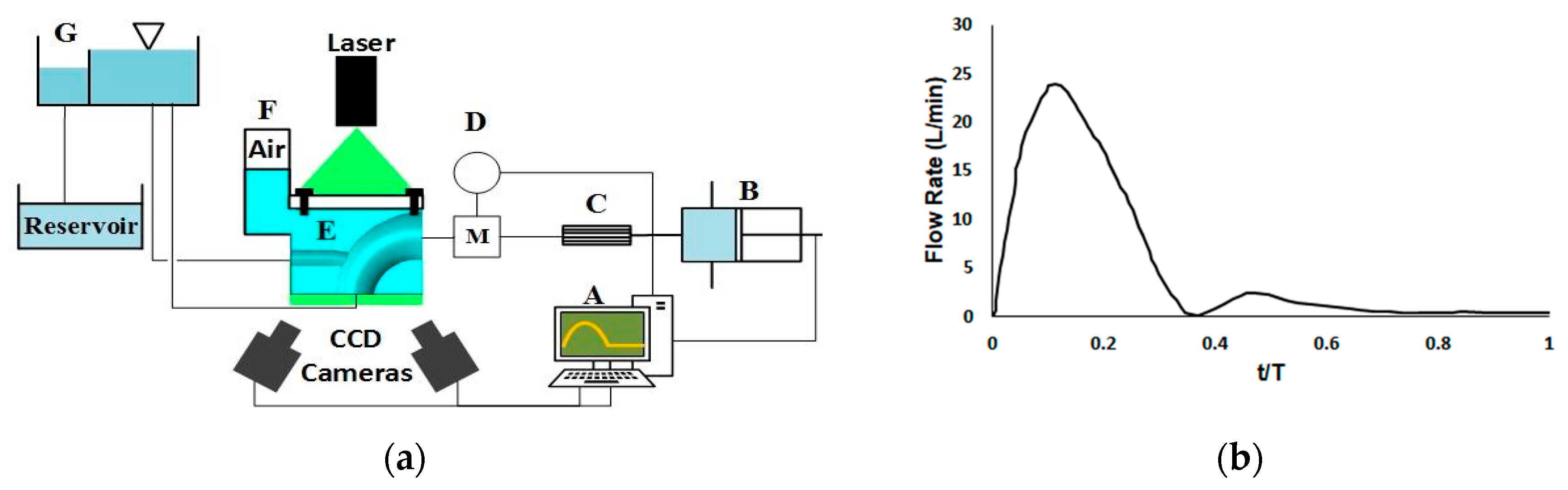
2.4. Stereoscopic Particle Image Velocimetry
For stereoscopic particle image velocimetry (SPIV) experimentation, the phantom was installed in a box that contained a pressurised water–glycerol fluid. The box was manufactured from 8 mm thick transparent acrylic sheet to facilitate optical access to the phantom. The sheets were laser cut and assembled. The water–glycerol ratio was 39:61 which has a viscosity 0.0117 Pa∙s and a density of 1156 Kg/m
3 at 20 °C, respectively [
17]. This viscosity is distinct from blood. However, it allows dynamic similarity by matching the Reynolds and Womersley numbers to the physiological conditions. Preserving the dynamic similarity, the Womersley and maximum Reynolds number were 18.52 and 1220, respectively. To match the Womersley number, an in vivo heart rate of 60 beats per min was used. The fluid was pressurised to 0.52 KPa to mimic the transmural pressure and surrounding tissue [
44,
45]. The working fluid matched the refractive index of the phantom to eliminate optical distortion [
24,
46,
47]. The refractive index was measured n = 1.417 using NAR-3T Abbe benchtop refractometer (ATAGO CO., LTD, Tokyo, Japan).
A water–glycerol solution was impregnated with Silver-Coated Hollow Glass Spheres particles (10 µm). A physiological flowrate waveform from a magnetic resonance imaging (MRI) study [
48] was scaled to enable dynamic similarity and was induced by a piston pump (
Figure 3b). The piston pump was actuated by a stepper motor and was connected to a flow straightener and an electromagnetic flowmeter. The phantoms’ outlets were connected to a header tank to mimic the impedance of the capillaries. A weir in the header tank controlled the outlet and back pressure (
Figure 3a).
Two TSI Powerview 4MP LS PIV cameras (TSI Inc., Shoreview, MN, USA), 60 mm Nikon lenses, a 120 mJ/pulse Nd-YAG laser (New Wave Solo 120 XT), and a light sheet forming lens train were used for SPIV. The light sheet was 2 mm thick. Coupled images captured the movement of particles in the working fluid and provided data for the TSI INSIGHT 4G software to reconstruct the flow fields in both phantoms. Since the current work focuses on the phantom manufacturing process, the PIV measurement was done on the phantom symmetry plane, and the planar velocity components are presented. The images from the two cameras were rotated and averaged to yield planar velocity fields. The time delay between the laser pulses was set at 1100 μs to capture the image pair. Two time-points were measured on the cardiac cycle; one at mid-acceleration and one at mid-deceleration. The analysis was phase locked with 20 pairs of images averaged at each phase. However, only the deceleration phase outcomes are presented since the reduction of the momentum is hypothesised to show clinically interesting flow separation. The images were captured with an f# of 11 for the lens aperture size. The laser power was modulated to achieve the best contrast in the seeding particles. The first phantom exhibited regions of significant light saturation and subsequent low contrast in the flow field when high laser powers were used. Hence, lower laser power was used to capture flow in the initial phantom.
Viewing the pressure box from an angle may cause optical distortion across the images. To overcome this issue, the images were calibrated by placing a Cartesian grid calibration target plane in the pressure box filled with working fluid. Disparity correction was employed to correct the misalignment between the light sheet and calibration target plane. Average intensity background was subtracted from the images to enhance the signal-to-noise ratio. The images were interrogated using Recursive Nyquist window refinement with the start and final window dimensions of 64 × 64 and 32 × 32 pixels, respectively. Cross-correlation was used to calculate the displacement vector field. Fast Fourier transform was used to calculate the cross-correlation function and reduce the computational time. The PIV uncertainty was not measured. The cameras were placed on the same side of the light sheet and aligned at 30° from the axis perpendicular to the object plane (
Figure 3a).
After SPIV analysis, the phantoms were dissected for mechanical measurement of their wall thickness. Wall thickness was measured at 100 points on different circumference locations along the phantom axis using an elastomer material dial thickness gauge. The measurement accuracy of the gauge was reported to be 0.0254 mm (0.001 inches).
3. Results
Figure 4 shows the initial and second phantom. Both phantoms appeared on visual inspection to be transparent, bubble free, and suitable for PIV analysis (
Figure 4). However, the 0.5 mm wall thickness of the initial phantom led to the failure of the brachiocephalic artery.
Figure 5 shows the refractive index testing of the phantoms. While neither phantom seems to distort the background image, the shape of the initial phantom can be easily discerned. Both phantoms are the same material, submerged in the same working fluid, and the images were taken using identical optical measurement settings. Hence, the visible outline of the initial phantom is likely to be due to the surface finish.
Figure 6 shows the raw PIV images of initial and second phantoms. The initial phantom has lower transparency compared to the second one and the seeding particles are barely visible. In addition, the surface of the initial model can be distinguished from the surrounding fluid.
Figure 7 shows the wall thickness variation distribution of both phantoms.
Figure 8 shows a cumulative distribution of the distortions in wall thickness. The median deviation of the initial phantom was 0.013 mm (quartiles (−0.117, 0.210), range = (−0.301, 0.514)) compared to the median deviation of the second phantom: 0.045 mm (quartiles = (0.013, 0.082), range = (−0.111, 0.206)).
Figure 9 shows the results of PIV analysis from both phantoms during the deceleration. Both models indicate flow rates that reduce to zero at the wall as expected. Note that the failure of the initial phantom in the brachiocephalic region led to the truncation of the arch to only the superior region. While this did not allow much information about the aortic flow field, it allowed for determination of the effects of surface finish on subsequent PIV analysis.
4. Discussion
This analysis showed the benefit of a novel mould-making technique for the manufacture of complaint phantoms. The initial phantom was manufactured using the method of Geoghegan et al. [
24]. However, the geometry of the phantom was more complex than phantoms presented in Geoghegan et al. Thus, the outcome using this manufacturing technique was unsatisfactory for PIV experimentation of the more complex geometry.
The second phantom had a more precise wall thickness than the initial phantom (
Figure 7 and
Figure 8). However, the initial phantom had a more accurate median wall thickness value. In particular, the second phantom was biased 0.1 mm too thick. When the phantoms’ final use in PIV analysis of haemodynamics and cardiovascular dysfunction is considered, it becomes apparent that precision is more important than accuracy. In particular, making the wall thickness 10% too large would change the apparent compliance by −10% (Equation (1)). However, the arterial behaviour would still be representative of haemodynamic flow as compliance can vary across individuals or disease states [
49]. Since the goal of this study was to obtain generalizable haemodynamic behaviours in the ascending aortic arch, this level of wall-thickness precision may be considered acceptable. However, the level of precision required for accurate simulation of patient-specific haemodynamics is likely to be higher. To date, there have been no published and accepted standards of wall thickness precision when generating silicone phantoms for PIV analysis of haemodynamics.
In contrast, the initial phantom had a much lower precision that led to variable compliance across the phantom. This variable compliance would distort the flow considerably. In particular, while one side of the initial phantom was 50% of the intended thickness, the other side was 150%. This could potentially lead to large and unphysiological transverse aberrations in the flow dynamics measured.
The bias observed across the two phantoms can be traced back to the manufacturing techniques used on the phantoms. In particular, the initial phantom used a 3D printed male mould that was smoothed using acetone. After smoothing, the male mould was scanned to produce a female mould that matched the dimensions of the male mould. The female mould was accurately manufactured via CNC milling of an Ebalta board. In contrast, the male and female moulds of the second phantom were both 3D printed independently. 3D printing reduced the manufacturing cost compared to CNC machining. In addition, CNC machining requires high operational skills compared to a 3D printing machine. To obtain sufficient manufacturing accuracy, the same 3D printer was used for both male and female moulds. The outcome of the first model may have been improved if the angular deflection correcting flanges used in the second model were incorporated within the design. Acetone core dissolving is a subtractive method and was used to smooth both moulds. Hence the cavity between moulds was slightly larger than intended. This could potentially be accounted for in future iterations of the casting process.
The large distribution of wall thickness of the initial phantom was due to misalignment of the male and female mould during casting. The alignment of the male mould could not be controlled while the two halves of the female mould were pressed together. The primary development of the second phantom manufacturing process was the end flanges that provide both rigidity and alignment of the ends of the male mould within the female mould. The first phantom effectively provided rigid support to the male mould but failed to provide sufficient alignment.
Figure 7 shows that the bias in wall thickness was consistently on one side of the phantom, which supports the idea that the lack of alignment was due to insufficient alignment from the end conditions. However, the relative contributions of each manufacturing step to the final precision distributions of the two models remain ambiguous.
Figure 9 shows a comparison of the PIV achieved by the two phantoms. The PIV algorithm yields zero flow at the wall boundaries. Hence both models show expected boundary behaviour. However, the second model yields more coherent near-wall velocities that are more conducive to consistent WSS calculation. The reverse flow observed in the brachiocephalic branch of the second phantom is most likely due to the positive pressure gradient caused by constriction of the aortic arch during deceleration. The same flow pattern was observed by Huang et al. [
11]. The recirculation and the reverse flow observed are indicative of low and intermittent WSS. These flow patterns are risk factors for CVD, atherosclerotic plaque formation, and endothelial cells development [
50,
51]. Assemat et al. [
52] produced an ex vivo study which showed stenosis risk areas in the aortic arch at the same regions where reverse flow and recirculation were observed in this study. A computed tomography examination of the aortic arch illustrated the same areas for atherosclerosis lesions [
53]. PIV of the first phantom yielded erratic velocity vectors that were not indicative of coherent flow, and the second phantom showed clear expected flow patterns. It is believed this is due to the variation in wall thickness caused by the misalignment of the internal core. The phantom would move laterally during experimentation due to the increased expansion of the thinner section and the force generated by the interaction of the fluid and the phantom. This led to large out of plane components of velocity that were not resolved with the PIV set up. These components of velocity would be greater than the thickness of the light sheet used. Furthermore, the poor surface finish of the initial phantom may have caused difficultly in tracking particles (
Figure 6). Thus, the images obtained were not sufficient for the PIV analysis and the cross-correlation algorithm yielded some arbitrary velocity vectors ranging between 0–0.05 m/s. As a result of these erratic vectors, the velocity scales shown are different.
This analysis was based on the outcomes of only two phantoms. Hence, the consistency of results cannot be assured. The cost of mould generation and time-consuming nature of casting limits the ability to generate more phantoms and a statistical analysis cannot be undertaken. The current geometry has a high level of curvature and contains a branch. These are the parameters which may limit the successful production of the phantom. Since the second method overcame these limitations, there is a degree of confidence that the method may be successful in more sophisticated cases. However, further conclusive studies are required to determine how wall thickness precision will be maintained in larger, more complex, arterial geometries.
The model experiences a sudden transition from compliant to rigid at the connection points. However, this transition does not mitigate the results at the arch and BCA junction. The current model was enlarged 50%, but the results’ applicability was maintained by dynamic similarity and compliance matching. Thin wall phantoms require high manufacturing precision. Therefore, for narrower arteries such as the coronary artery, the model will need a larger scale to achieve a wall thickness suitable for the manufacturing method developed here. This phantom size will also require an increased field of view for PIV analysis.
PIV analysis has been established as the leading methodology in experimental fluids [
54]. However, the methodology has certain limitations in cases when fluid–solid boundary interaction must be modelled. In particular, most applications of PIV require solid boundary materials to be optically transparent and have a refractive index that matches the working fluid. Furthermore, when specific wall compliance is required, the wall thickness of the solid boundary must be precisely achieved. This research has shown the limitations of established moulding techniques when complex shapes are required. The research also shows the potential benefit of using rigid supports and fully 3D printed moulds in the generation of phantom moulds.
Importantly, it is unexpected that a fully 3D printed mould would produce a successful thin-walled phantom. In particular, the printer may bridge the gaps across the male and female moulds, leading to a series of holes in the phantom after mould dissolution. Equally, the surface of most ABS additive manufacturing machines is too rough for the development of moulds for PIV. Hence, they must be smoothed. While it would be possible for acetone to be used as a smoothing agent, it is likely that the acetone would re-deposit previously dissolved ABS on the moulds. This would lead to a large variation of wall thickness and compliance and would leave holes across the phantom. Hence, phantoms of complex thin-walled shapes should be manufactured in male and female parts to allow for smoothing.

 ,
, 


