Article

Latent Leakage Fault Identification and Diagnosis Based on Multi-Source Information Fusion Method for Key Pneumatic Units in Chinese Standard Electric Multiple Units (EMU) Braking System

Institute of Rail Transit, Tongji University, Shanghai 201804, China
*
Author to whom correspondence should be addressed.
Appl. Sci. 2019, 9(2), 300; https://doi.org/10.3390/app9020300
Submission received: 23 December 2018 / Revised: 8 January 2019 / Accepted: 9 January 2019 / Published: 15 January 2019
(This article belongs to the Special Issue Fault Detection and Diagnosis in Mechatronics Systems)

Abstract

:
To identify and diagnose the latent leakage faults of key pneumatic units in the Chinese standard Electric Multiple Units (EMU) braking system, a multi-source information fusion method based on Kalman filtering, sequential probability ratio test (SPRT), and support vector machine (SVM) is proposed. The relay valve is taken as an example for research. Firstly, Kalman’s state estimation function is used to obtain the innovation sequence, and the innovation sequence is input into the SPRT model to help recognize latent leakage faults of the relay valve. Using this method, the problem of the incomplete training set of the traditional SPRT method due to the change of the braking level and the vehicle load is solved. Secondly, the eight time-domain parameters of the relay valve input and the output pressure signal are extracted as fault characteristics, and then input to the support vector machine to realize the internal and external leakage fault diagnosis of the relay valve, which provides a reference for maintenance. Finally, this method is verified by the fault simulation data by quickly identifying latent leakage faults and diagnosing the internal and external leakage at a fault recognition rate of 100% by SVM under small sample conditions.

1. Introduction

Energy-savings, speed, and comfort are favored by passengers of the “Fuxing” Chinese Standard Electric Multiple Units (EMU). While people enjoy the convenience of standard EMUs, their safety is widely emphasized. As one of its nine key technologies, the EMU’s brake system directly affects its operational safety and efficiency. The relay valve, EP valve, and empty and load valve are the key pneumatic units of the brake system, which determine the reliability and availability of service and emergency braking [1,2,3].
However, during long-term operation, leakage faults may occur due to the wear of rubber seals, spring fatigue, and mechanical jams caused by grease failure. These faults may degrade the performance of the pneumatic unit and even cause functional failures, such as the brakes not releasing or providing insufficient braking power, all of which can affect operational safety and efficiency [4,5,6,7,8,9]. Although the existing brake system has a diagnostic function, this function offers a system-level fault diagnosis and does not have a component-level fault warning function. When the leakage of a pneumatic unit occurs, the most noticeable result is a change in pressure. Consequently, the pressure state can be monitored to identify and diagnose latent leakage problems. As a statistical test method, sequential probability ratio test (SPRT) is commonly used for on-site monitoring and isolation of abnormalities. Compared to conventional threshold detection methods, SPRT requires the smallest average number of samples for the fault detection of signals, which means that a developmental fault signal can be indicated earlier with the same accuracy. Meanwhile, considering the particularity of the braking system—that is, the braking force required by the vehicle under a different vehicle load and braking level is different—it is difficult for the traditional SPRT to prepare a complete training set. In this paper, the Kalman predictor is used to preprocess the pressure signal, and the innovation sequence obtained by Kalman filtering is used as the detection signal of SPRT.
Due to the distinct impacts of different leakage faults, this paper extracts fault characteristic parameters to realize the fault diagnoses of relay valve leakages, to provide guidance for maintenance decisions and save maintenance costs. At present, the most efficient diagnostic methods for hydraulic (pneumatic) system faults mainly include the fault tree [10], the Back Propagation (BP) neural network [11,12,13], and the expert system [14]. Among them, the fault tree has great limitations in online diagnosis. The BP neural network method has a slow convergence speed, which lengthens the training time, and makes it easy to get the local minimum; conversely, the amount of data required by the expert system is relatively large, and the diagnostic results can be inaccurate. The support vector machine (SVM) [15,16] algorithm has special advantages in small sample, high dimensional, and nonlinear problems. From a theoretical point of view, the SVM algorithm obtains the global optimal solution, which makes up for the fact that the BP neural network method can easily fall into the local extremum. At the same time, the SVM can obtain higher diagnostic accuracy under small sample training and fixes the expert system method’s low diagnostic rate in the case of incomplete samples.
In this paper, the key valve shared by the service braking and emergency braking of the brake system—the relay valve—is taken as an example for research. The multi-source information fusion method of the Kalman filter, SPRT, and SVM is proposed to be applied to the standard EMU for identifying and diagnosing latent leakage faults in the critical pneumatic units of the brake system. Considering the limited number of relay valve faults and the research of the leakage mechanism of the relay valve, the leakage fault simulation test is carried out to obtain the fault sample data and to verify the feasibility of the method.

2. Standard EMU Brake System

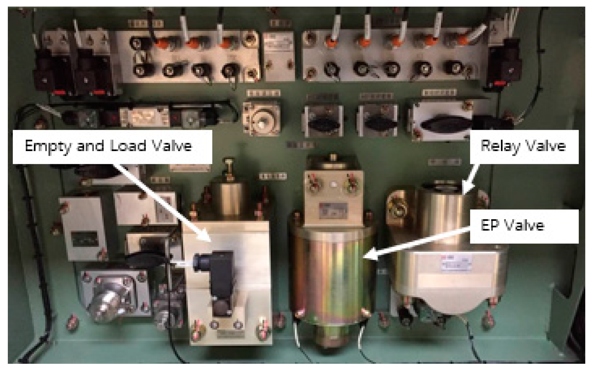
2.1. Standard EMU Brake Control Device

The standard EMU brake system brake control device (Figure 1) is mainly composed of the EP (Electro-Pneumatic) valve, the relay valve, the empty and load valve, and other pneumatic units. Its functions are mainly used for service braking and emergency braking, which both need to be achieved through the relay valve. By controlling the current of the EP valve, the pre-control pressure (CV1) proportional to the current is output to the relay valve in service braking, and the relay valve outputs a large flow of equivalent compressed air to the pressurized cylinder. During emergency braking, the pre-control pressure (CV2) of the empty and load valve is output to the relay valve. According to the high-pressure priority function, the larger pressure is used as the air pressure output of the pressurized cylinder [1,17,18]. The relay valve determines the reliability and availability of service and emergency braking.

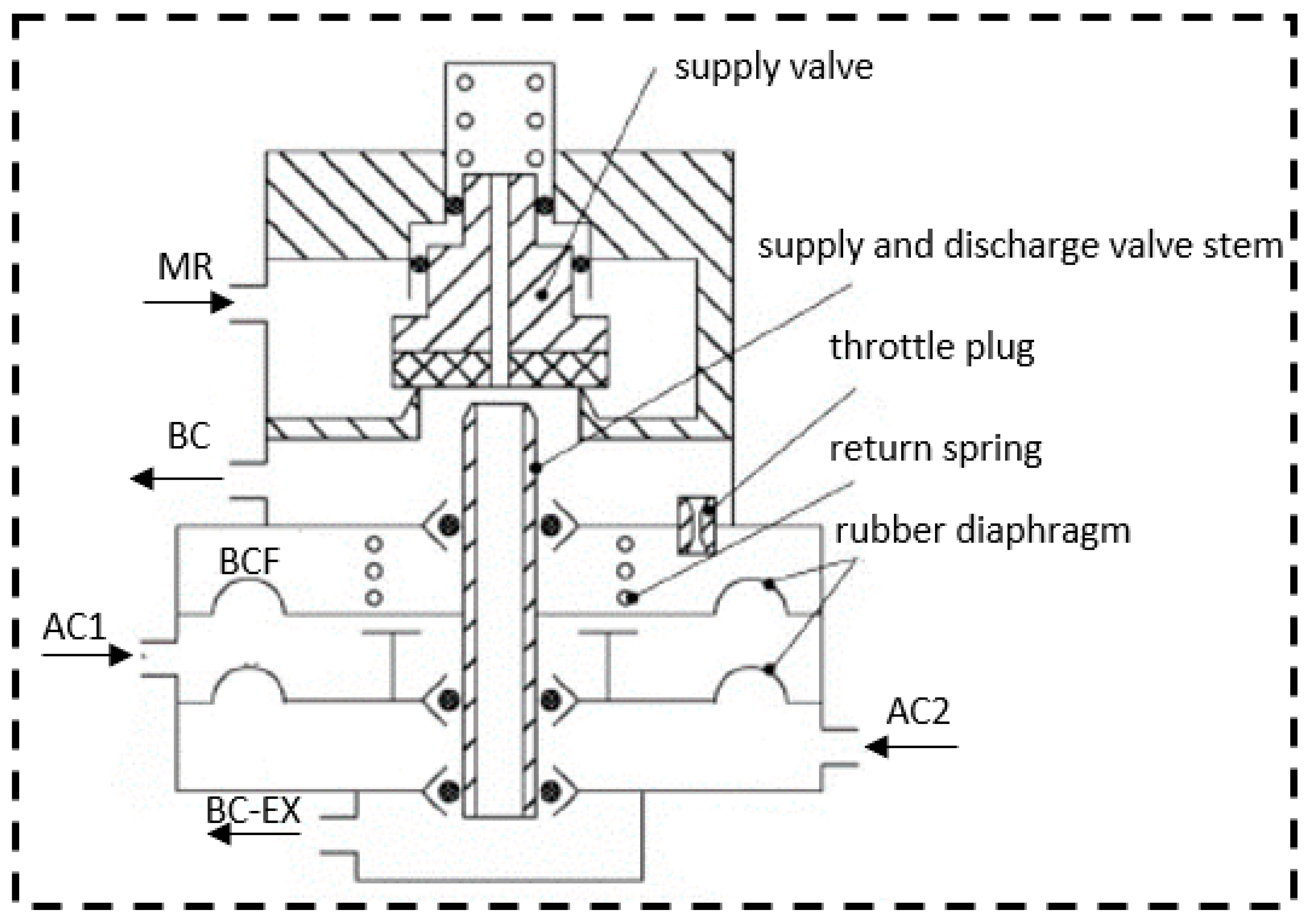
2.2. Relay Valve Structure and Leakage Fault

The relay valve (Figure 2) is mainly composed of a supply valve, a supply and discharge valve stem, a return spring, a throttle plug, rubber diaphragms, a feedback chamber (BCF), and pre-control chambers (AC1, AC2) [6]. The upper chamber of the supply valve is connected to the brake supply cylinder (MR), and the lower chamber is connected to the pressurized cylinder (BC).
According to the structure and working principle of the relay valve, the leakage fault can be divided into “internal leakage” and “external leakage” from the gas flow direction and its influence. Its definition, impact, and causes are shown in Table 1.

3. Multi-Source Information Fusion Method

In this paper, the statistical analysis method SPRT is used to analyze and process the relay valve output pressure signal to identify latent leakage faults in the relay valve. In addition, data fusion technology is used to find effective data in redundant information and evaluate the target through certain algorithms and evaluation strategies. Data fusion can occur at different levels of information, including the data layer, feature layer, and decision layer [19]. The machine learning method of SVM, which is widely used in pattern recognition, is used to fuse multiple fault features, and the combined fault features are used for the internal and external leakage diagnosis of the relay valve.

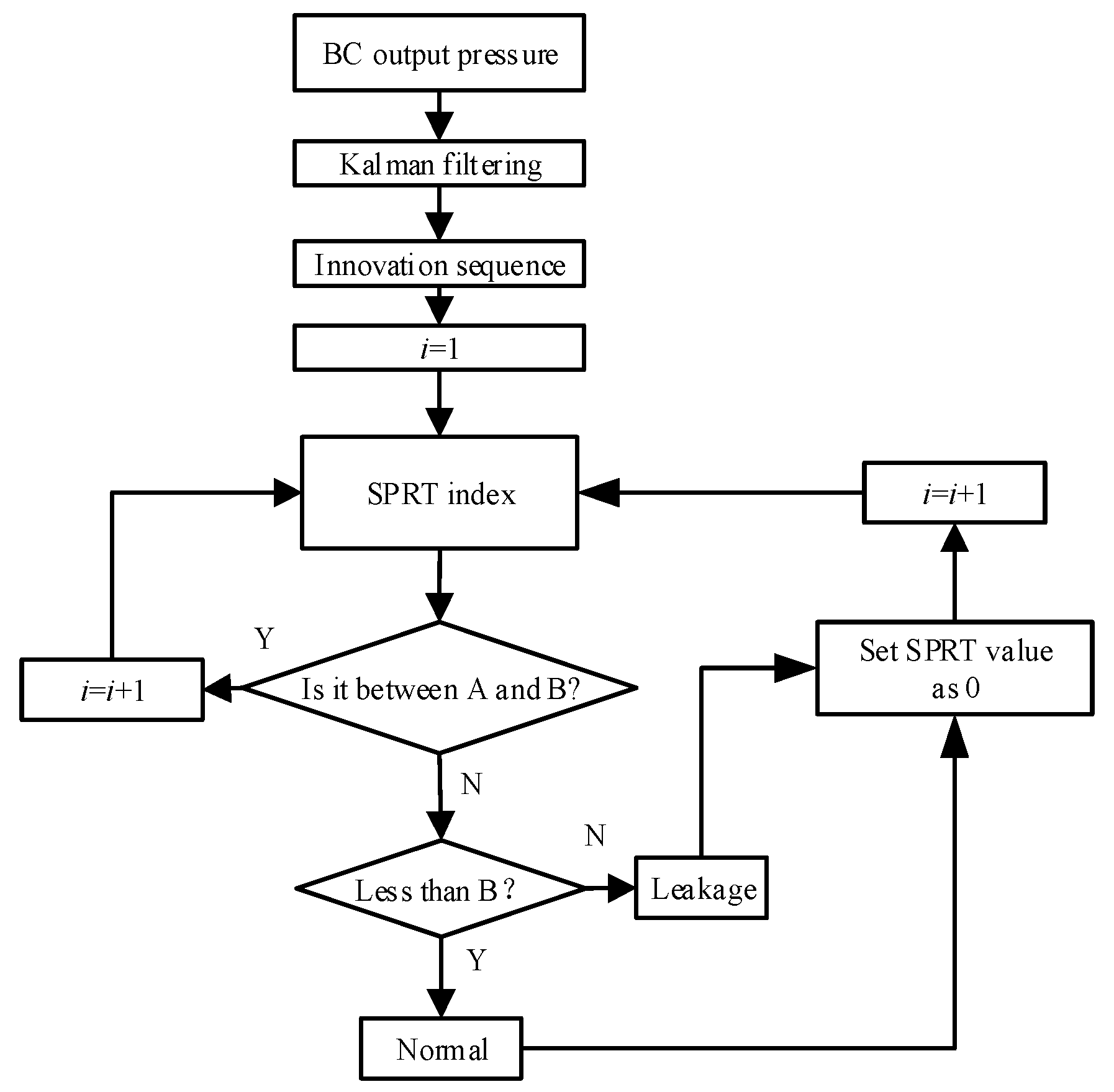
3.1. Leakage Detection Based on Kalman Filter and SPRT

The traditional SPRT method requires a training set to perform anomaly detection. However, the brake cylinder pressure is different due to the influence of the vehicle load and the braking level. The training set has difficulty achieving full coverage, which hinders the use of SPRT in the on-line detection of latent leakage faults in the relay valve.
The Kalman filter optimally estimates the state of the system through the input and output signals. This filter is especially suitable for the prediction of motion behavior with frequent changes in motion state and can realize real-time prediction [20]. In this paper, the innovation sequence of the Kalman filter is input into the SPRT model to realize the online detection function.

3.1.1. Kalman Filtering

Since the relay valve pressure signal is one-dimensional, the Kalman filter theory of the scalar signal is employed. For the characteristics of the relay valve pressure signal sequence collected by the BC pressure sensor in real time, the following mathematical model is established:
s ( k ) = s ( k 1 ) + w   ( k 1 )
x ( k ) = s ( k ) + n   ( k )
where s ( k ) represents the sequence of state signal, i.e., the signal model; w ( k ) is a white noise sequence with zero mean, often referred to as system noise; x ( k ) is the observation sequence, i.e., the observation model; and n ( k ) is also a white noise sequence with zero mean, often referred to as measurement noise.
According to the linear least mean square criterion, the recursive algorithm of the Kalman filtering model is as follows:
Prediction error variance:
p 1 ( k ) = p ( k 1 ) + σ w 2
Optimal filtering gain:
b ( k ) = p 1 ( k ) [ p 1 ( k ) + σ n 2 ] 1
Filtering error variance:
p ( k ) = p 1 ( k ) b ( k ) p 1 ( k ) = b ( k ) σ n 2
Filtering equation:
s ^ ( k ) = s ^ ( k 1 ) + b ( k ) [ x ( k ) s ^ ( k 1 ) ]
Innovation sequence:
e ( k ) = x ( k ) s ^ ( k 1 )
where σ w 2 is the system noise and σ n 2 is the measurement noise.
Due to the delay of the state estimation, the innovation sequence can extract the inflection point of the BC pressure signal sequence, and the abnormal point can be identified.

3.1.2. Sequential Probability Ratio Test

SPRT is a statistical decision-making method that optimizes the selection of the sample size. It does not pre-specify the number of observational sample groups but continues to increase the data until the required threshold is met in the inspection process [21].
The abnormality of the relay valve leakage is mainly the statistical mean shift [22]. Therefore, the simulation test in this paper has two hypothesis H0 and H1.
  • Normally, the sequence satisfies the null hypothesis H0: μ = μ0;
  • In leakage, the sequence satisfies the alternative hypothesis H1: μ = μ0 + Δμ.
where Δμ > 0 means the internal leakage and Δμ < 0 means the external leakage.
The joint probability density of the random sequence is
P 0 k = 1 ( σ 2 π ) k exp ( 1 2 σ 2 i = 1 k ( x i μ 0 ) 2 ) ,
P 1 k = 1 ( σ 2 π ) k exp ( 1 2 σ 2 i = 1 k ( x i μ 0 Δ μ ) 2 ) ,
where k is the sampling points.
In the SPRT test, the decision on the hypothesis is based on the value range of Equation (10).
L R = P 1 k P 0 k ,
The SPRT algorithm is as follows:
λ ( k ) = ln ( L R ) = ln ( P 1 k P 0 k ) = Δ μ σ 2 i = 1 k ( x i μ 0 Δ μ 2 ) ,
where λ ( k ) is the test index and L R (Likelihood Ratio) is the probability ratio. The upper and lower limits are specified according to the allowable false alarm rate α and the missing alarm rate β.
A = ln ( 1 β α ) ,
B = ln ( β 1 α ) ,
where A is the upper limit and B is the lower limit.
The recursive formula is
λ ( k ) = λ ( k 1 ) + Δ μ σ 2 ( x k μ 0 Δ μ 2 ) ,
Figure 3 shows the detection process based on the Kalman and SPRT method.

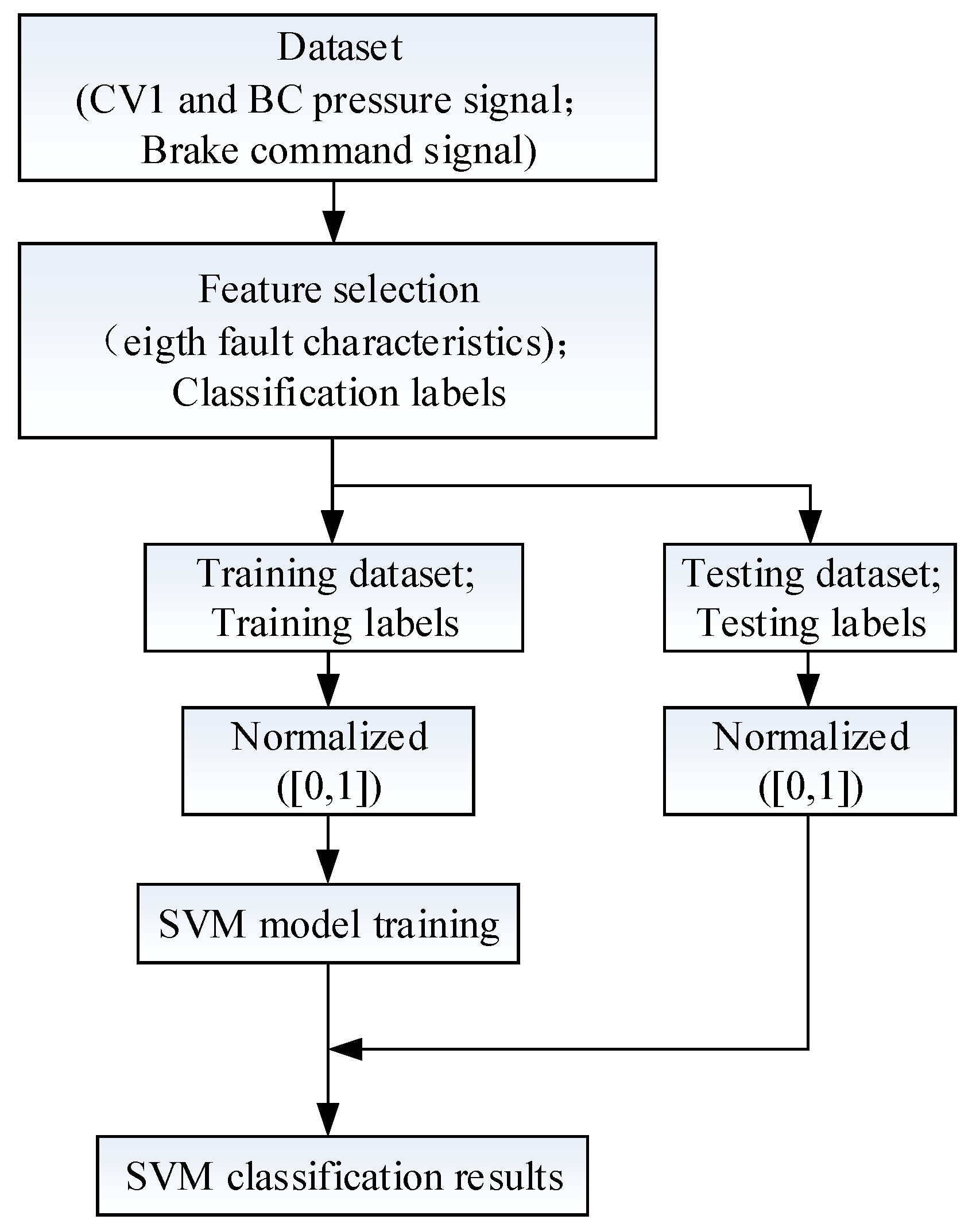
3.2. Internal and External Leakage Diagnosis Based on Support Vector Machine

3.2.1. Relay Valve Leakage Fault Characteristic Parameters

To diagnose the leakage modes more accurately, it is necessary to extract the fault characteristic parameters. In addition to the statistical mean shift mentioned in Section 3.1.2, and considering that the leakage will affect the response characteristics of the relay valve, eight fault characteristics shown in Table 2 are extracted; these fault characteristics correspond to the three stages of the relay valve: braking, holding, and releasing.

3.2.2. Support Vector Machine

SVM is a data-driven machine learning algorithm. The special advantages of the SVM algorithm in small sample, high dimensional, and nonlinear problems have made it a popular fault diagnosis method in recent years. SVM contains two typical algorithms: Support Vector Classification (SVC) and Support Vector Regression (SVR). In this paper, the SVC algorithm [23] is adopted as the diagnosis method.
For a sample training dataset, D = { ( x i , y i ) | i = 1 , 2 , n } , x i R n , y i { ± 1 } , n is the sample size. The nonlinear mapping maps the input vector x from the original space R n to a high-dimensional space Z.
Constructing the optimal linear classification hyperplane y = ( w T · φ ( x i ) ) + b in high-dimensional space.
The classification constraint is
s . t . { y i [ ( w T · φ ( x i ) ) + b ] 1 + ε i 0 ε i 0
m i n w , b , ε [ 1 2 w T w + C i = 1 n ε i ]
where w is the normal of the hyperplane, b is the intercept, φ ( x i ) is the nonlinear mapping, ε i is the slack variable, and C is the penalty factor.
Define the Lagrangian function as follows:
L = 1 2 w T w + C i = 1 n ε i i = 1 n β i ε i i = 1 n α i { y i [ ( w T · φ ( x i ) ) + b ] 1 + ε i }
where α i , β i are Lagrange multipliers.
Obtaining partial derivatives of w , b , ε i and setting them as 0, and replacing the inner product [ φ T ( x i ) · φ ( x j ) ] with the kernel function K ( x i ,   x j ) :
m a x α i = 1 n α i 1 2 i = 1 n j = 1 n α i α j y i y j K ( x i ,   x j ) ,
s . t . { i = 1 n y i α i = 0 0 α i C
The optimal classification function can be obtained by solving Equations (18) and (19):
f ( x ) = s g n [ i = 1 n α i y i   K ( x i ,   x j ) + b ]
Based on the SVC algorithm above and the SVM toolbox in MATLAB (Matrix Laboratory), and given a set of training instances marked as belonging to one or the other of the two categories, the SVM training algorithm creates a model that assigns a new instance to one of the two categories. Since the SVM original classifier is only suitable for a two-class problem; the “One vs One” method is adopted to achieve three pattern recognition in this paper, and the eight time-domain characteristic parameters of the pressure signal are used as the input of the SVM to establish the training and testing datasets. The relay valve leakage fault diagnosis implementation process based on SVM is shown in Figure 4.

4. Experiment Verification

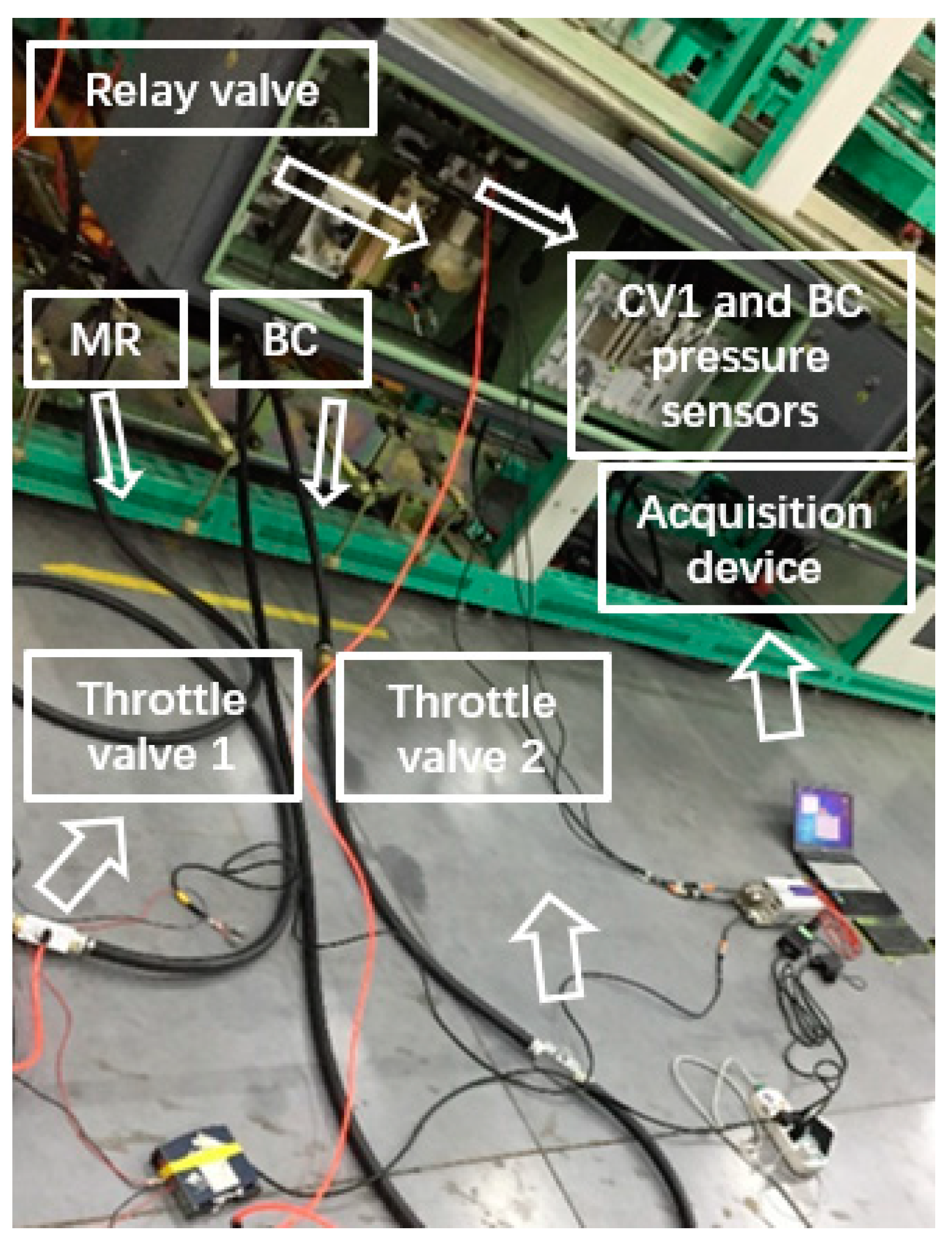
4.1. Fault Simulation and Sample Acquisition

The fault injection method is to artificially bring a demand fault to the system model, causing the system to malfunction or fail under certain operating conditions, and to observe the response of the system, thereby providing the tester with results-related testing process [24].
Fault diagnosis is based on the fault sample. Since the fault data of the relay valve is limited, a leakage fault simulation test platform (Figure 5) based on the structure and working principle of the relay valve is developed in this paper. This test simulates the internal and external leakage of the relay valve The test data under normal and leakage conditions are collected as sample data.
Table 3 lists the relay valve fault injection methods for internal and external leakage.
The “relay valve leakage simulation test platform” is mainly composed of the brake control device, the acquisition device, and the throttle valve leakage fault simulation device. The “normal” test is carried out 5 times, and the internal and external “leakage” simulation tests are carried out 10 times, respectively. The CV1 and BC pressure sensors collect the input and output pressure data of the relay valve. The sampling rate of the acquisition device is set to 1000 Hz to ensure that the sampling accuracy is sufficiently high to avoid influencing the leakage state.

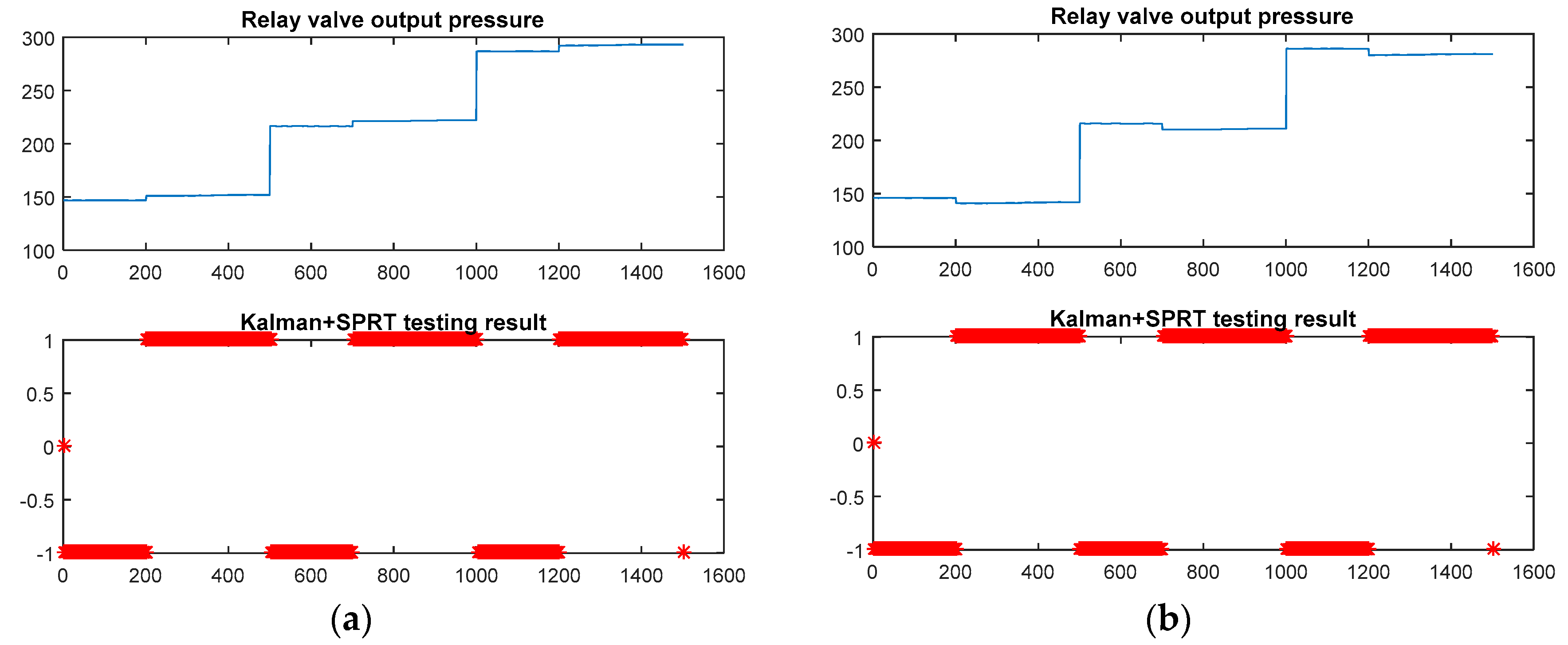
4.2. Leakage Identification

In the leakage identification verification, the related parameter are as follows: false alarm rate α = 0.001, missing alarm rate β = 0.005 [25]. The SPRT indexes are normalized to [−1,1], while “1” indicates leakage, “−1” means normal, and the interval means that the result cannot be judged and the acquisition process continues. The Kalman and SPRT test models are programmed according to Figure 3 using MATLAB software. The test results are shown in Figure 6.
Figure 6 shows that the internal and external leakage in different braking levels (three in this paper) can be detected quickly and correctly. The BC pressure is about 5 kPa higher than the normal value when the internal leakage occurs, while the BC pressure is about 5 kPa lower than the normal value when the external leakage occurs. The leakage of 5 kPa is undetectable by the existing diagnostic system. However, there is obviously a hidden danger. Increased leakage may cause the brakes to not release or to apply insufficient braking force, thereby affecting the safety and efficiency of the EMU. The method proposed in this paper can be used to predict and warn relay valve leakage.

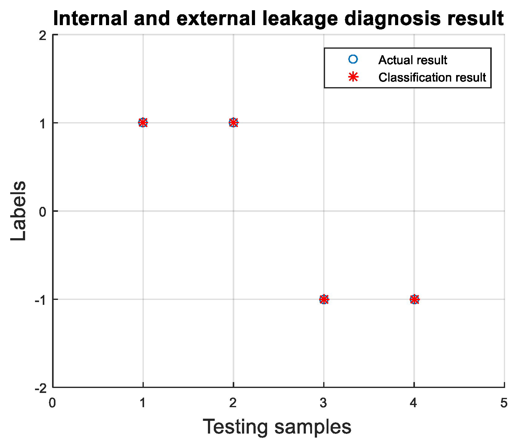
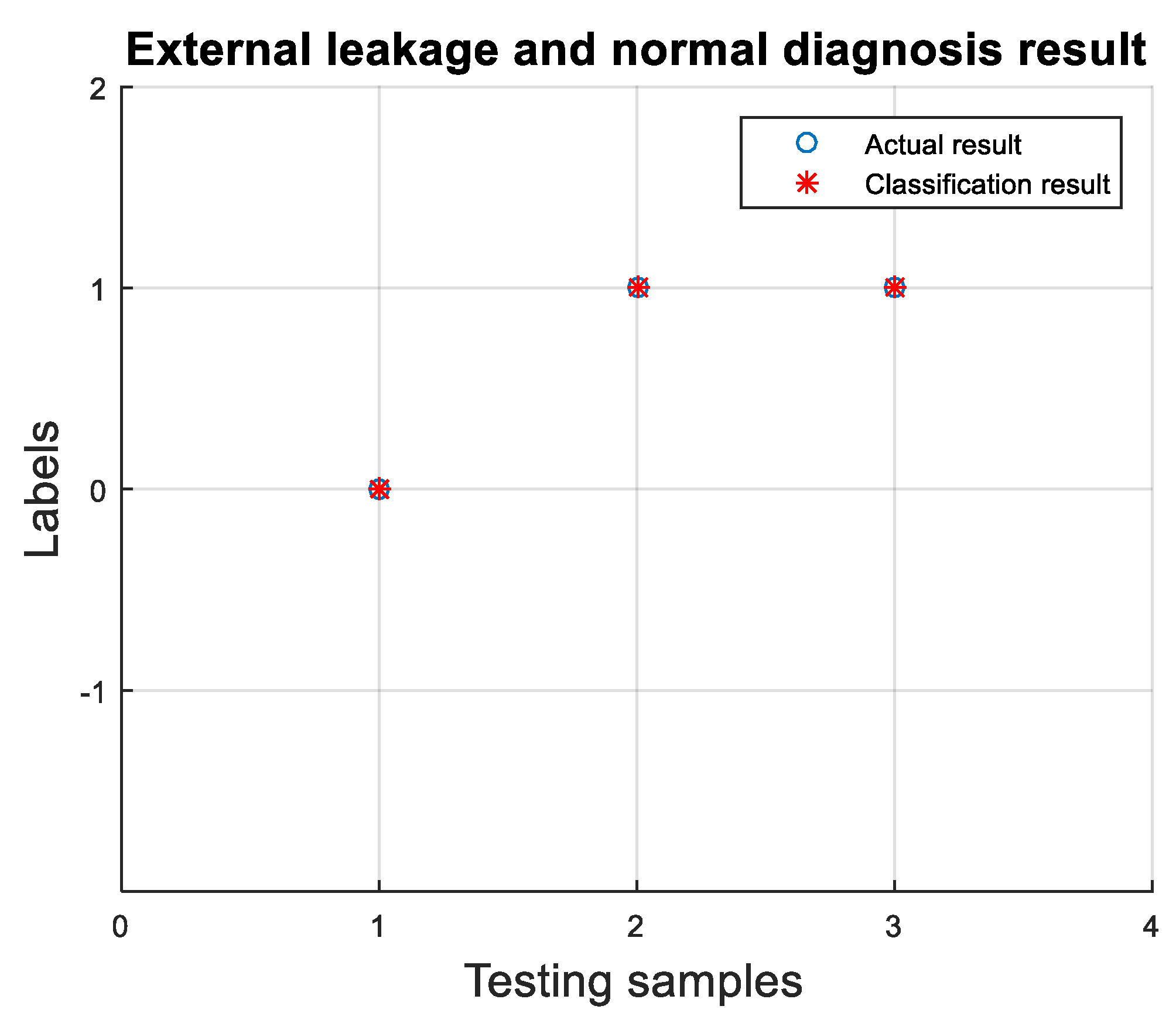
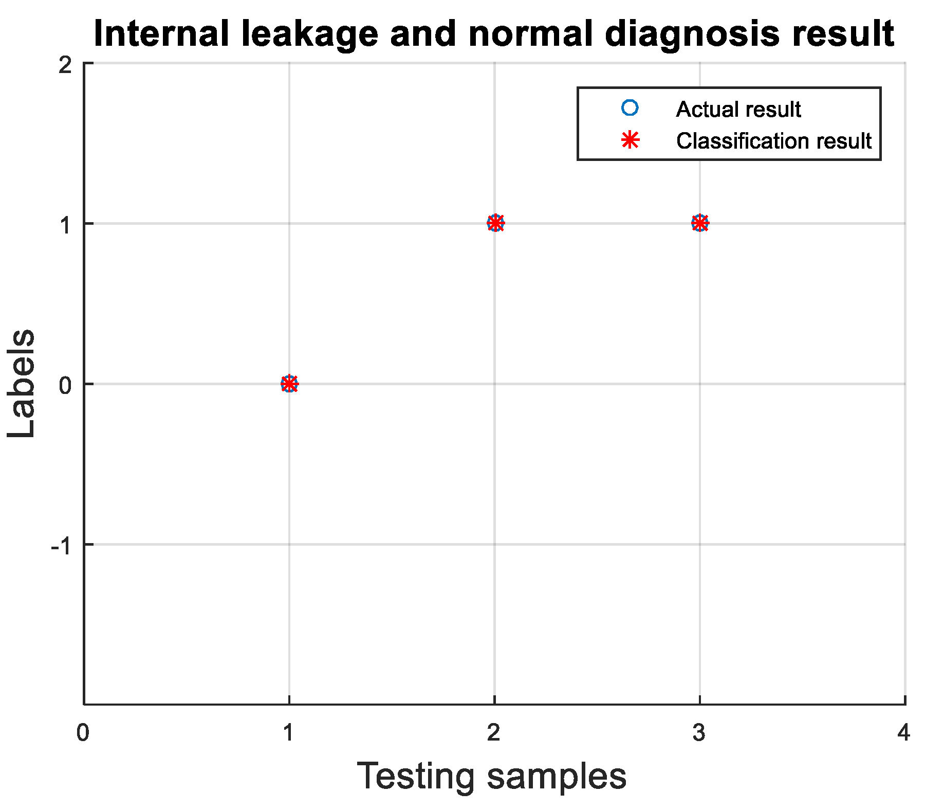
4.3. Leakage Diagnosis

According to the method described in Section 3.2.1, Table 4 lists the fault characteristic parameters obtained after processing the data of the simulation test.
In this paper, internal leakage and external leakage are classified first: “1” stands for internal leakage, and “−1” stands for external leakage. The diagnostic results are shown in Figure 7. Next, internal leakage and normal sequence are classified: “1” stands for internal leakage, and “0” stands for normal. The diagnostic results are shown in Figure 8. Finally, for normal and external leakage, “0” stands for normal, and “1” stands for external leakage. The diagnostic results are shown in Figure 9.
As can be seen from Figure 7, Figure 8 and Figure 9, the SVM based on the eight time-domain fault characteristics of the relay valve input and output pressure can diagnose normal, internal or external leakage at a fault recognition rate of 100%. Therefore, this method can be used to diagnose latent leakage faults in the relay valve and provide maintenance guidance.

5. Conclusions

(1) To predict the latent leakage faults of the pneumatic units of the Chinese standard EMU brake system, an identification method based on Kalman and SPRT is proposed, and the relay valve is used as an example. The results show that a slight leakage of 5 kPa can be effectively detected, which proves the effectiveness of this method. Therefore, this method can help detect relay valve leakage faults, so that maintenance personnel can predict the health status of the relay valve in advance and improve the availability of the brake system.
(2) To diagnose the internal and external leakage of the relay valve, a method based on SVM is proposed. Using the fault injection method, two types of typical leakage faults are simulated on the relay valve leakage fault simulation test platform, and the CV1 and BC pressure signals of three kinds of working conditions are collected: no leakage, internal leakage, and external leakage. Eight time-domain failure characteristics are then extracted for a fault diagnosis based on SVM. The diagnostic results show that this method can predict the internal and external leakage of the relay valve under a 100% fault recognition rate, which provides a practical method for diagnosing the faults of relay valve leakage. At the same time, this method also provides guidance for maintenance and reduces maintenance costs.

Author Contributions

Conceptualization, J.Z.; Data curation, J.D.; Funding acquisition, J.Z.; Methodology, J.Z.; Software, F.F.; Validation, J.D.; Writing–original draft, J.D.

Funding

This research was funded by National Key R&D Program in the 13th Five-year Plan of China, grant number 2018YFB1201603.

Acknowledgments

The authors thank the brake control research group members in Brake Technology Research Center, Institute of Rail Transit, Tongji University, for many good suggestions and discussions.

Conflicts of Interest

The authors declare no conflict of interest.

References

  1. Wang, F.; Ma, L.; Zhu, X.-Y.; Niu, R. Simulation study on performance of relay valve for high-speed EMU brake system. Fluid Mach. 2013, 41, 43–46. [Google Scholar]
  2. Tian, C.; Cheng, M.; Pan, L.; Wu, M. Fault feature extraction of service air braking of subway train. J. Tongji Univ. Nat. Sci. Ed. 2014, 42, 84–90. [Google Scholar]
  3. Liu, Y.; Cheng, G.; Zhuang, G.; Wang, F. Redesign and analysis of relay valve for high-speed electric multiple unit braking system. Hydraul. Pneum. Seals 2015, 35, 42–45. [Google Scholar]
  4. Wu, M.; Tao, Z.; Tian, C.; Cheng, M. Fault feature analysis of service brake not releasing caused by relay valve leakage. Chin. J. Sci. Instrum. 2013, 34, 1864–1871. [Google Scholar]
  5. Wu, M. Research on Microcomputer-Controlled Direct Electropneumatic Brake System. Ph.D. Thesis, Tongji University, Shanghai, China, 2006. [Google Scholar]
  6. Zhu, H. Reliability Study on the Balance Valve of DA01 Train on Shanghai Metro Line 1. Ph.D. Thesis, Shanghai Jiaotong University, Shanghai, China, 2011. [Google Scholar]
  7. Wu, M.; Wang, X.; Tian, C. Reliability of relay valve of brake system for rail vehicles. J. Southwest Jiaotong Univ. 2009, 44, 365–369. [Google Scholar]
  8. Zhang, M. Faults and Preventive Measures of Train Braking System on Beijing Metro Line 13. Mod. Urban Rail Transit 2009, 12, 58–60. [Google Scholar]
  9. Huo, W. Failure Analysis and Solution of Flash Reporting Braking Not Releasing for CRH380AL EMUs. Oper. Maint. 2017, 14, 12–14. [Google Scholar]
  10. Tang, H.; Wu, Y. Fault diagnosis of pumping hydraulic system of concrete pump truck based on T.-S. fuzzy fault tree. Appl. Res. Comput. 2012, 29, 561–568. [Google Scholar]
  11. Tang, H.B.; Wu, Y.X.; Hua, G.J.; Ma, C.X. Fault Diagnosis of Internal Leakage in Hydraulic Cylinder Based on PCA and BP Neural Network. J. Cent. South. Univ. Nat. Sci. Ed. 2011, 42, 3709–3714. [Google Scholar]
  12. Narendra, K.S.; Parthasarathy, K. Identification and control of dynamical systems using neural networks. IEEE Trans. Neural Netw. 1990, 1, 4–27. [Google Scholar] [CrossRef]
  13. Xuanyin, W.; Xiaoxiao, L.; Fushang, L. Analysis on oscillation in electro-hydraulic regulating system of steam turbine and fault diagnosis based on PSOBP. Expert Syst. Appl. 2010, 37, 3887–3892. [Google Scholar] [CrossRef]
  14. Liu, Z.; Cai, Z.; Mu, Z.; Zhang, S. Research on the construction of fault diagnosis expert system for aircraft hydraulic system based on CLIPS. J. Nav. Aeronaut. Eng. Inst. 2011, 26, 45–48. [Google Scholar]
  15. Liu, J.; Li, Y.-F.; Zio, E. A SVM framework for fault detection of the braking system in a high speed train. Mech. Syst. Signal. Process. 2017, 87, 401–409. [Google Scholar] [CrossRef] [Green Version]
  16. Liu, J.; Zio, E. A scalable fuzzy support vector machine for fault detection in transportation systems. Expert Syst. Appl. 2018, 102, 36–43. [Google Scholar] [CrossRef]
  17. Sun, J.; Ren, L.; Wu, Z.; Qi, H. Optimization on throttle hole of FD-1 relay valve of CRH2 EMU air braking system. Comput. Aided Eng. 2011, 20, 10–15. [Google Scholar]
  18. Ma, L.; Pang, S.; Wu, M.; Wang, F. Flow Characteristics Simulation Analysis on Relay Valve of CRH2 EMU. Fluid Mach. 2014, 42, 30–34. [Google Scholar]
  19. Hunag, M.-G.; Fan, S.-C.; Zheng, D.-Z.; Xing, W.W. Research progress of multi-sensor data fusion technology. Sens. Microsyst. 2010, 29, 5–9. [Google Scholar]
  20. Qiao, S.-J.; Han, N.; Zhu, X.-W.; Shu, H.-P. A Dynamic Trajectory Prediction Algorithm Based on Kalman Filter. Acta Electron. Sin. 2018, 46, 418–423. [Google Scholar]
  21. Wang, H.; Zhao, X.; Yang, D. Missile Vibration Fault Diagnosis Based on MSET and SPRT. Meas. Control. Technol. 2015, 34, 59–62. [Google Scholar]
  22. Zuo, J.-Y.; Ding, J.-X.; Peng, S.; Hu, G. Fault Feature Extraction of Relay Valve Leakage Based on Test for Standard EMU Brake System. In Proceedings of the 2017 2nd International Conference on Applied Mechanics and Mechatronics Engineering (AMME 2017), Shanghai, China, 26 September 2017; pp. 353–359. [Google Scholar]
  23. Liu, Z.; Yang, K.; Zhang, R.; Li, X.; Li, J. Fault diagnosis research for full hydraulic braking system of trackless tyred vehicle. Ind. Mine Autom. 2016, 42, 30–34. [Google Scholar]
  24. Sun, J.; Li, Y.; Yang, X. A Theoretical Framework for Fault Injection Research. Miniat. Microcomput. Syst. 1999, 20, 816–819. [Google Scholar]
  25. Niu, G.; Zhao, Y. Locomotive Brake System Fault Detection and Isolation Based on Bond Graph Model. J. Tongji Univ. Nat. Sci. Ed. 2015, 43, 894–899. [Google Scholar]
Figure 1. Standard Electric Multiple Units (EMU) Brake Control Device.
Applsci 09 00300 g001
Figure 2. Relay valve structure.
Applsci 09 00300 g002
Figure 3. Leakage detection process based on the Kalman and sequential probability ratio test (SPRT) Method.
Applsci 09 00300 g003
Figure 4. Leakage diagnosis process based on support vector machine (SVM) Method.
Applsci 09 00300 g004
Figure 5. Relay valve leakage simulation test platform.
Applsci 09 00300 g005
Figure 6. (a) Relay valve internal leakage Kalman and SPRT test results and (b) relay valve external leakage Kalman and SPRT test results.
Applsci 09 00300 g006
Figure 7. Relay valve internal and external leakage diagnosis result.
Applsci 09 00300 g007
Figure 8. Relay valve internal leakage and normal diagnosis result.
Applsci 09 00300 g008
Figure 9. Relay valve external leakage and normal diagnosis result.
Applsci 09 00300 g009
Table 1. Relay valve leakage mode.
Leakage ModeGas Flow DirectionImpactCauses
Internal leakageMR to BCThe output pressure is higher, the braking release is slow, and even braking does not releaseSupply valve assembly vulcanizing parts aging; return spring aging; supply valve stuck
External leakageBC to BC-EX (external atmosphere)The output pressure is lower; too low will trigger abnormal emergency brakingSupply valve assembly vulcanizing parts aging; supply valve stuck
Table 2. Leakage fault characteristic parameters.
CodeLeakage Fault Characteristic ParametersDefinition
ACV1 steady-state pressureThe CV1 pressure average of the holding phase
BBC steady-state pressureThe BC pressure average of the holding phase
CFollowing errorDifference between BC steady-state pressure and CV1 steady-state pressure
DMaximumAfter the brake command is triggered, the maximum value of the BC pressure during the pressure holding phase
EMinimumAfter the brake command is triggered, the minimum value of the BC pressure during the pressure holding phase
FDegree of volatilityAfter the brake command is triggered, the standard deviation of the BC pressure during the pressure holding phase
GResponse timeTime required for BC pressure to rise from 10% to 90% of target pressure
HDelayed releasing timeFrom when the brake command is cancelled to when the BC pressure drops to 40 kPa
Table 3. Relay Valve Leakage Fault Injection Method.
Leakage ModeFault Injection Method
internal leakageBy connecting a throttle valve 1 between the air supply port of the relay valve and the output port of the relay valve
external leakageBy connecting a throttle valve 2 between the relay valve output port and the atmosphere
Table 4. Fault characteristic parameters.
NumberFailure ModeA (kPa)B (kPa)C (kPa)D (kPa)E (kPa)FG (s)H (s)
1Normal254.788237.425−17.3624239.726236.280.580.772.277
2Normal254.596237.233−17.3628239.495236.0790.580.7672.288
3Normal254.643237.361−17.2819239.409236.1260.530.7722.277
4Normal254.589237.325−17.2635239.583236.3050.580.7652.277
5Normal254.613237.397−17.2157239.642236.320.570.7722.299
6Internal257.242250.324−6.91807252.409244.4271.030.7592.498
7Internal257.082250.154−6.92832251.97244.38910.7662.523
8Internal257.068250.1−6.96781251.945243.9581.120.7622.544
9Internal257.054250.064−6.98958251.988244.3251.010.7692.581
10Internal256.893249.886−7.00637251.914244.2581.060.7682.546
11Internal257.102250.12−6.98136252.063244.7321.010.7812.53
12Internal256.965250.025−6.94063251.832244.7360.940.7732.564
13Internal256.875249.966−6.90872251.957244.3440.990.7682.521
14Internal256.962250.029−6.93281251.855244.4971.040.7652.539
15Internal256.75249.804−6.94583251.717243.9551.030.7642.548
16External254.824236.758−18.0662239.408235.5830.60.7692.257
17External254.665236.528−18.1379239.082235.4740.550.7742.248
18External254.507236.307−18.2238.991235.0250.570.7722.271
19External254.397236.225−18.1716238.961235.1390.560.7692.256
20External254.477236.324−18.1534238.859235.1140.580.7742.273
21External254.48236.407−18.0735238.808235.2630.580.7742.241
22External254.437236.337−18.1001239.041235.1270.60.7762.281
23External254.342236.157−18.1849238.591235.1120.530.7962.257
24External254.407236.308−18.0993239.136235.1680.560.7732.255
25External254.673236.703−17.97239.59235.5470.580.7782.282

