Article

Joining of Carbon Fiber Reinforced Plastic to Aluminum Alloy by Reactive Multilayer Films and Low Power Semiconductor Laser Heating

1
Institute of Laser Engineering, Beijing University of Technology, 100 Pingle Yuan, Chaoyang District, Beijing 100124, China
2
Department of Mechanical, Aerospace and Biomedical Engineering, University of Tennessee, 1512 Middle Drive, Knoxville, TN 37996, USA
3
School of Mechanical Engineering, Jiangnan University, 1800 Lihu Avenue, Wuxi 214000, Jiangsu, China
4
College of Materials Science and Engineering, Beijing University of Technology, 100 Pingle Yuan, Chaoyang District, Beijing 100124, China
*
Author to whom correspondence should be addressed.
Appl. Sci. 2019, 9(2), 319; https://doi.org/10.3390/app9020319
Submission received: 13 November 2018 / Revised: 3 January 2019 / Accepted: 8 January 2019 / Published: 17 January 2019
(This article belongs to the Special Issue Selected Papers from the NMJ2018)

Abstract

:
This study investigated the characteristics and strength of the dissimilar joints between carbon fiber reinforced plastic (CFRP) epoxy composites and aluminum alloys using two different heating methods, Ni/Al reactive multilayer films (RMF) and a low power continuous wave diode laser. To enhance the adhesion, the top resin layer of the CFRP and the surface of the aluminum alloy were patterned by femtosecond laser. Polycarbonate (PC) was used as a filler material during the joining processes. ANSYS simulation was applied to elucidate the thermal kinetics of the self-propagation reaction and the thermal profile, and evaluate the possibility of joining CFRP to aluminum using Ni/Al RMFs. The SEM image of the cross-section shows that melted PC flowed into the CFRP–aluminum alloy interface, suggesting strong mechanical bonding. A tensile strength of 9.5 MPa was reached using Ni/Al multilayers as heat sources, which provides a new way for joining CFRPs and aluminum alloys in space or under water.

1. Introduction

Carbon fiber reinforced plastic (CFRP) has been widely used as an important material for industry applications due to its excellent characteristics, such as high strength to weight ratio, excellent fatigue resistance, and little corrosion [1,2]. The application of CFRP–metal structures for industry applications is also very promising. Aluminum alloys are widely applied in the aircraft and automotive industries, which need lightweight and highly corrosion resistant parts. Due to the advantages of CFRP and aluminum alloys, joining these two materials to produce hybrid components with high functional flexibility has attracted manufacturers’ interests. Both CFRP and aluminum alloys are extensively used in the aircraft and automobile industries. However, joining CFRP and aluminum alloys is still a challenging issue due to the very different chemical and physical properties between these materials.
A number of joining methods have been used for joining CFRP–aluminum alloys, such as adhesive joining [3], friction stir joining [4], ultrasonic joining [5] and laser joining [6]. Adhesive joining is a conventional process for joining plastics, including CFRP to metals [7]. Rhee et al. investigated the surface treatment of CFRP and aluminum to improve the fracture toughness of adhesively-bonded CFRP–aluminum joints [8]. Ar+ ion irradiation and plasma treatment were performed on the surface of CFRP and aluminum. Scanning electron microscopy (SEM) examination of fracture surfaces showed that the toughness increased by 72% when CFRP was treated by Ar+ ion irradiation. The fracture load of ion beam-treated CFRP/untreated aluminum can reach 16 kN, and the shear strength is about 5 MPa. Min et al. applied friction stir blind riveting to join CFRP to aluminum alloy plates [4]. They found that brittle delamination of the CFRP sheet caused a 10% reduction in the maximum tensile loads of the CFRP–aluminum joints. Balle et al. described joining aluminum-wrought alloy (AA 5754) to CFRP with polyamide 66 matrix [9]. Microstructure characterization showed that an intensive connection between AA 5754 and CFRP had developed, and no damage of the CFRP was observed. A tensile shear strength of about 30 MPa was determined for AA 5754/CFRP–PA 66 joints. Besides those traditional joining methods, laser joining has also attracted much interest due to its low thermal effect, noncontacting and high efficiency [10]. Chen et al. investigated the laser joining process of joining polyethylene terephthalate (PET) to a titanium plate [11]. The highest failure stress of the laser joining process was about 10 MPa. Lambiase et al. reported that with the laser-assisted laser joining of a thermosetting matrix CFRP to polycarbonate (PC), the effective strength of the joints reached 8.4 MPa, which is comparable to the results of 9 MPa obtained by the adhesive joining process [12]. Jung et al. joined polyacrylonitrile-type CFRP to aluminum alloy using a continuous wave diode laser with a line-shaped beam [13]. The tensile shear load of the joints was about 3000 N, and the corresponding shear strength was less than 10 MPa.
Recently, reactive multilayer films (RMFs) have attracted much attention for applications in joining processes. RMFs are especially attractive for aerospace or underwater joining and repairing [14,15]. RMFs can provide energy as a local heat source due to the heat released by the exothermic reaction of the multilayers to form intermetallic compounds [16]. The reaction can be ignited by electrical, thermal, laser pulse, or mechanical striking. For joining purposes, the RMF was placed between two similar or dissimilar materials/components with two layers of preset or precoated solder [17]. Wang et al. used freestanding Ni/Al RMF to melt AuSn solder layers and thereby joined aluminum specimens under pressure of 100 MPa [18]. The shear strength of 32 MPa indicated that AuSn solder should be fully molten for at least 0.5 ms to ensure a full wetting and establish strong joints. Most of the RMF joining studies were focused on metal–metal joining under a high pressure or using furnace-based joining procedures. However, RMF joining for plastics to metal has seldom been explored.
In this paper, we present both RMF joining and laser joining of thermosetting CFRP with epoxy matrix to an aluminum alloy (AA 6061). Using RMF as a local heat source can reduce the heat affected zone of the base material, joining CFRP to aluminum without affecting the performance of the hybrid components. PC was used as a filler material for the wettability between the CFRP and aluminum. The surface of both the CFRP and aluminum were pretreated with femtosecond laser in order to obtain a better mechanical joint. The aim of this study was to offer an innovative joining solution that can reduce the power/pressure requirement for joining and provide a better joint. For this study, the effect of a prepatterned surface of CFRP and aluminum for joining will be demonstrated, and the numerical simulation of the RMF joining process will be discussed.

2. Materials and Methods

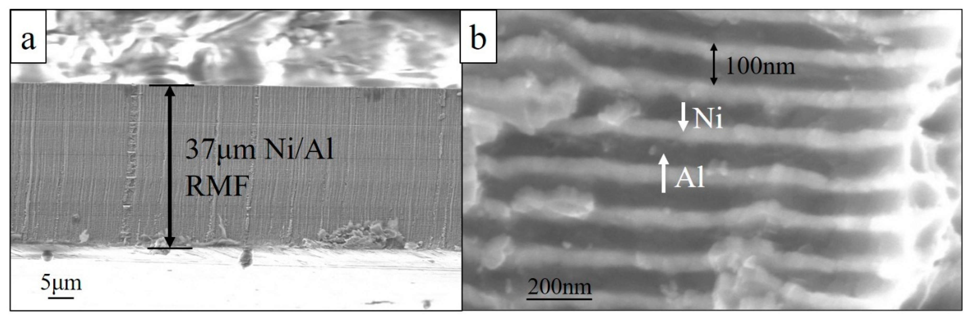
2.1. Preparation of Ni/Al RMFs

Ni/Al bilayers were deposited directly on polyimide (PI) substrate using a modified Varian 3118 electron beam evaporator with a deposition controller (Leybold XTC/2). Before deposition, the PI substrates were rinsed sequentially in an ultrasound bath by ethanol and deionized water. Then Ni/Al RMFs were prepared by electron beam physical vapor deposition. During deposition, the pressure inside the chamber was maintained lower than 5 × 10⁻⁴ Pa. The deposition controller was used to control the deposition rate and thickness of the films. The atomic ratio of the Ni/Al film was 1:1. For each bilayer, the thickness of Ni was about 40 nm while Al was about 60 nm. A Ti layer of 30 nm was added as the bottom layer and intermittently to help the film adhere to the PI substrate and prevent delamination during deposition.

2.2. Pretreatment of CFRP and Aluminum Alloy

A femtosecond fiber laser (FLCPA-05U20UTN, Calmar Laser Inc., Palo Alto, USA) was used to pattern the surface of the CFRP and aluminum, and the laser power was 1 W. This process was utilized to remove the superficial epoxy matrix of the CFRP and pattern the aluminum to obtain a stronger mechanical joint. The wavelength of the laser was 1064 nm, the pulse width was 300 fs, and the pulse repetition rate was 120 kHz. The diameter of the laser spot was about 10 μm, and the laser scanning speed was 10 mm/s. After laser treatment, the CFRPs and aluminum alloys were cleaned in an ultrasonic bath by ethanol and deionized water. The purpose of this process was to clean up the micro/nanoparticles remaining on the surface of the CFRP and aluminum after laser treatment, in order to obtain better mechanical contact with the molten PC.

2.3. RMF Joining and Laser Joining Processes

For the RMF joining process, the Ni/Al reaction was ignited via a 13 V DC power source. A total of 5 MPa pressure was applied to ensure close contact between the CFRP, RMFs, and aluminum. The schematic image of the joining process is shown in Figure 1a. The RMF joining parameters are listed in Table 1. The laser joining process is shown in Figure 1b. The temperature achieved by the PC during RMF joining was estimated computationally using ANSYS. The simulation parameters are shown in Table 2 [19]. The thermal conductivity and heat capacity were assumed to be constant. A slice of cross-section was applied on analysis of the temperature during the RMF joining. For the laser joining process, the laser used for joining was a 300 W continuous wave diode laser, the size of the laser beam was 5 mm × 2 mm, and the wavelength of the laser was 806 nm. The laser joining parameters are listed in Table 3. The laser irradiation was on the top aluminum surface, and the irradiation time was 5 s. The lap tensile test was used to determine the tensile strength of the joints, as shown in Figure 1c.

2.4. Characterization Techniques

The morphology and cross-section structure of the Ni/Al RMFs and fracture surfaces of the joints were characterized by a Zeiss Auriga SEM. The chemical composition of the RMFs and the fracture phases were investigated by a Panalytical Empyrean X-ray Diffractometer (XRD). Jade 6.0 was used to analyze the XRD data. The differential scanning calorimetry (DSC) of the as-deposited Ni/Al RMF was evaluated by a Netzsch STA 449C Jupiter Thermo-microbalance. The heating rate was 10 °C/s. The reaction speed of the Ni/Al RMF was determined by a PowerView HS-650 highspeed camera. The tensile strength of the joints was determined by ZHIQUP Precision Instruments 1500D, illustrated in Figure 1c. The upper clamp moved at the speed of 0.1 mm/s, and the value of the force was obtained in real time through the sensor inside the clamp. For each mechanical test, at least three specimens were tested.

3. Results and Discussion

3.1. Characterization of RMFs and Laser Pretreated CFRP and Aluminum Surfaces

Ni/Al multilayers were deposited onto the PI substrate, as shown in Figure 2. Alternating Ni and Al layers were detectable, and the total thickness achieved 37 μm. The thickness of the Ni layer (white) was about 40 nm, and the thickness of Al layer (grey) was about 60 nm, thus the bilayer thickness of the Ni/Al RMF was about 100 nm. The atomic ratio of the Ni/Al RMF was kept 1:1. The XRD result in Figure 3a shows that the as-deposited film was pure Ni and Al without obvious intermixing between the layers. Figure 3b presents the DSC measurement of the Ni/Al RMF; the calculated heat release of the total reaction is about 1270 J/g. Figure 4 shows the screenshots of the self-propagating reaction of the Ni/Al RMF. The length and width of the film was 25 mm by 5 mm. The film was ignited from the left side and the self-sustained reaction wavefront spread from the left to the right side in 8 ms. The reaction process was accompanied by a visible flame and the spread rate was about 3.2 m/s. Figure 5 presents the surface of femtosecond-treated CFRP and aluminum. As seen in Figure 5a, the epoxy matrix on the top of the CFRP surface was completely removed, and the carbon fibers were exposed outside. The aluminum surface was patterned with grids, as shown in Figure 5b.

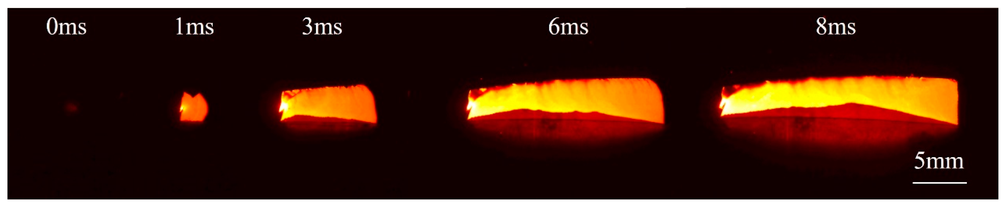
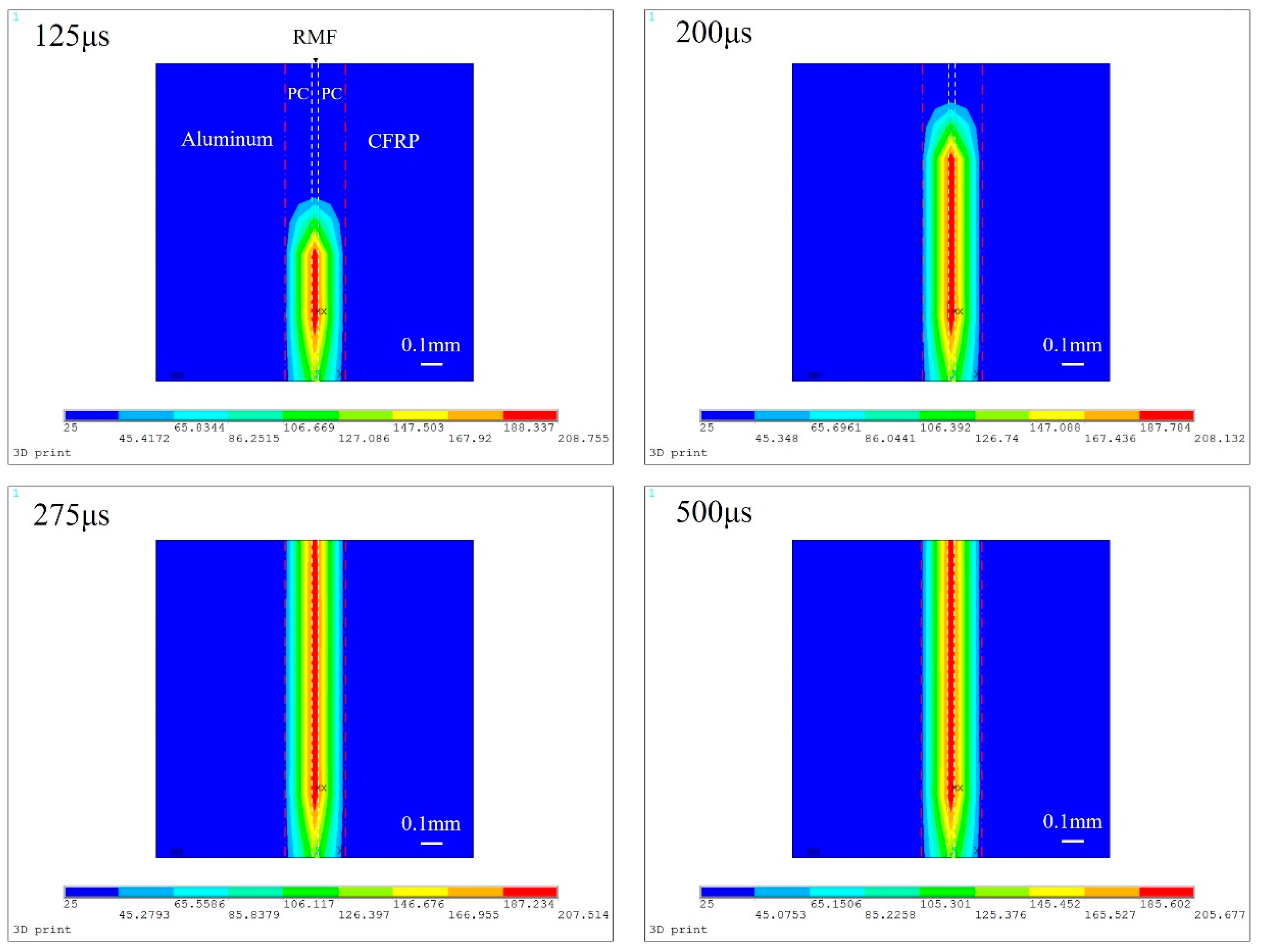
3.2. Joining of CFRP to Aluminum Using RMFs

For the RMF joining processes, freestanding Ni/Al RMFs with different thicknesses were used as the local heat source. The thermoplastic CFRP used in this experiment was an epoxy matrix, thus before joining the laser treated CRFP and aluminum surface were coated with molten PC as a filler material. PC is a thermoplastic material, and due to its attractive processing and physical properties such as low weight, flame-retardation, and high impact resistance, it has been widely used in electronic, automotive, and aircraft components [20,21]. The deflection temperature of PC is around 130 °C, which can deform after absorbing heat released from the reacted RMFs. Due to the rough surface treated with the laser, molten PC can fill in the rough surface to form a mechanical bond. When the RMFs were ignited, the heat release of the reaction melts the PC again on both the CFRP and aluminum side and thus form a joint. Considering RMF as a fast-moving heat source that releases heat at a constant speed simplified the complex situation to a heat conduction model, avoiding the complicated reactions between the RMF layers. The moving speed was the same as the reaction speed, and the heat releasing speed can be calculated by the DSC result. Figure 6 shows snapshots of the ANSYS simulation of the temperature evolution and distribution in the joint at various time steps. The simulation explained the cross-section temperature distribution of the joint. In the middle of the joint was the RMF, which as it is ignited by electrical heating can reach over 208 °C in 100 μs. The PC around the RMF absorbed the heat released from the reaction and thus reached over 150 °C, which is higher than the heat deflection temperature of PC at around 130 °C. Due to the presence of 5 MPa pressure on the aluminum and CFRP plate, molten PC wrapped around the reacted RMF or permeated from the cracks on the reacted RMF to the other side of the PC, and after cooling down, the PC solidified again and formed a joint. Figure 7 shows the shear strength of the joints using RMFs with different thicknesses. For each processing parameter, at least three trials were conducted. The difference is reflected by the error bar. As seen in Figure 7, thicker RMF can improve the shear strength of the joint, since the thicker film can generate more heat than a thin film, therefore the PC on both sides of the thicker RMF can melt more completely, resulting in a higher shear strength. Using two pieces of RMF definitely increased the heat release of the reaction, thus forming a much stronger joint. The highest shear strength of 9.5 MPa was obtained using two pieces of RMF, with the RMF thickness of 48 μm.
Figure 8 shows the fracture surfaces of both the CFRP and aluminum sides. As seen in Figure 8a,b, the PC has embedded into both the carbon fiber and aluminum and formed a sound mechanical joint. The fracture happened partially on the aluminum side and partially on the PC, which can be proved by the dimples seen in Figure 8c, indicating a ductile fracture was formed. Some parts of the reacted RMF still remained in the fracture surface.

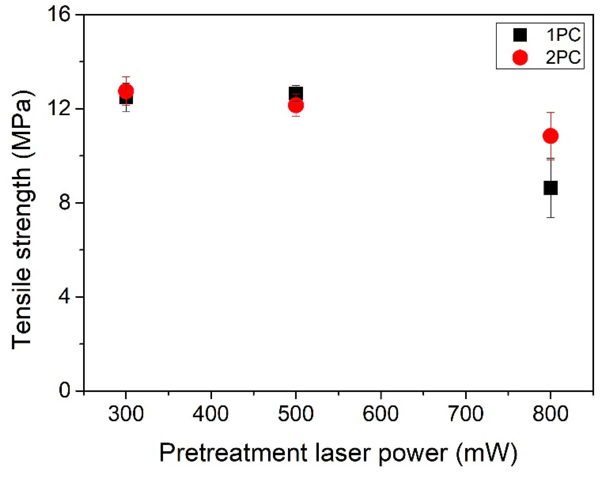
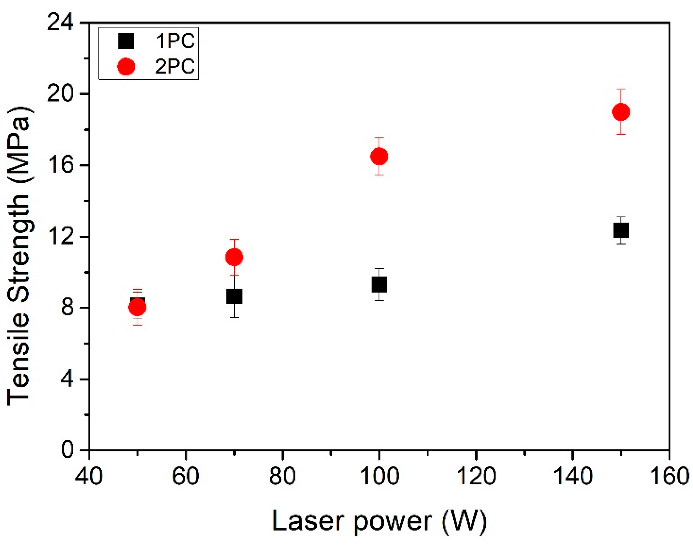
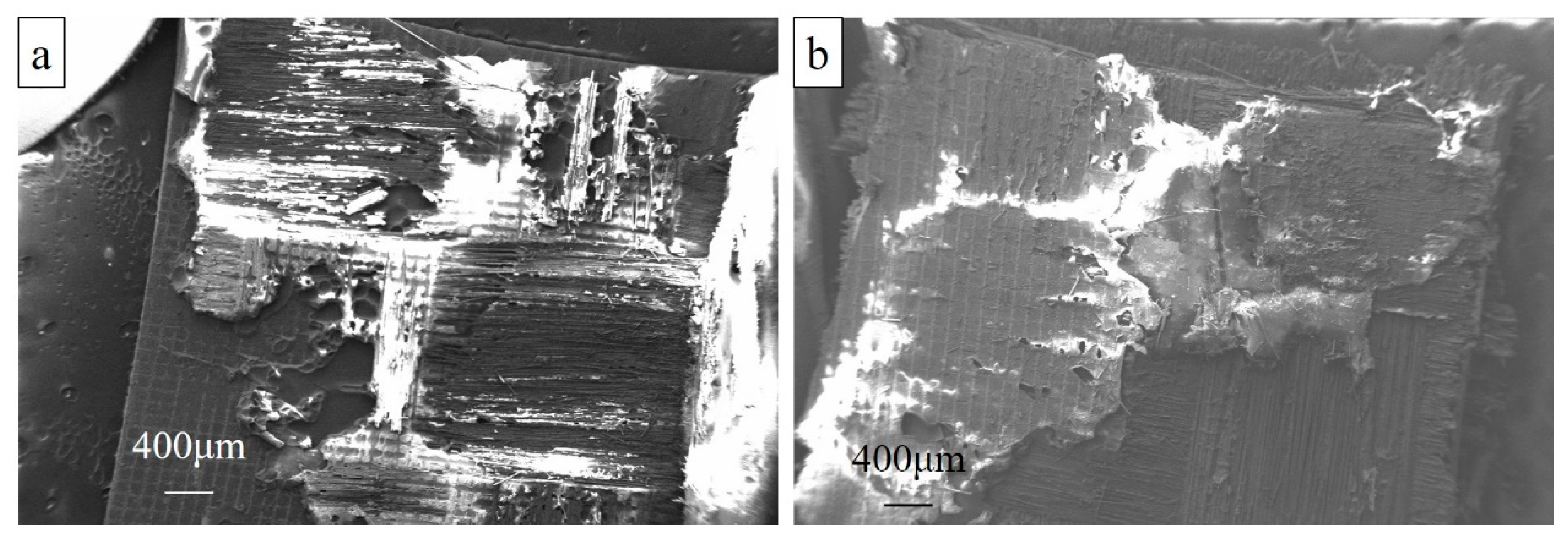
3.3. Joining of CFRP to Aluminum Using a Diode Laser

For the laser joining process, a PC sheet with a thickness of 150 μm was used as a filler material for joining. The sample size was 5 mm × 20 mm. Before joining procedures, the effect of pretreatment laser power on the tensile strength of CFRP/aluminum joints was investigated, as shown in Figure 9. When the CFRP was pretreated with a 300 mW and 500 mW femtosecond laser, the tensile strength of the obtained joints remained stable at about 12 MPa. As the laser power increased to 800 mW, the tensile strength of the joints decreased to around 9 MPa. Two pieces of PC sheet can improve the tensile strength of joints between CFRP and aluminum. In the investigation of joining with different laser powers, the surface of the CFRPs were treated with a 300 mW femtosecond laser. A 50 W to 150 W diode laser was applied on the CFRP/aluminum laser joining; while the laser power was above 150 W, the temperature of the joints was higher than the decomposition temperature of the PC sheet and epoxy matrix of CFRP, resulting in a joint with no shear strength.
Figure 10 shows the tensile strength of joints under different joining laser powers. With the increase of laser power, the tensile strength of the joints increased gradually, and with two pieces of PC sheets, the CFRP/aluminum joints reached a higher tensile strength. The highest tensile strength of 20 MPa was obtained using the laser power of 150 W and two pieces of PC sheets were used as a filler material. Figure 11 presents the fracture surfaces of both sides of the 20 MPa CFRP/aluminum joint. Only a small amount of PC remained in the fracture surface. The fracture happened in the carbon fibers, and a layer of carbon fiber adhered to the surface of the aluminum, which demonstrated that the real tensile strength of the joint was higher than 20 MPa, and higher than the strength of carbon fibers.

4. Conclusions

In this study, Ni/Al RMFs were used as a heating source for joining epoxy matrix CFRP and aluminum alloys. Dense and reliable joints were obtained and the highest shear strength of 9.5 MPa was reached using Ni/Al RMFs with the thickness of 96 μm under the pressure of 5 MPa. The total reaction time was less than 100 ms. Ni/Al RMFs provide a novel method for joining CFRP and aluminum without significant power requirements or the weight of equipment transported into space. Laser direct joining of CFRPs to aluminum alloys was also investigated. Femtosecond pretreatment on the surface of CFRPs and aluminum alloys proved to be efficient for improving the tensile strength of the joints. The highest tensile strength of 20 MPa was obtained when using a 150 W diode laser for joining, with the help of 300 μm PC sheets. These studies may pave the way for the development of light-weight materials, CFRPs and aluminum alloys for joining and repairing in space or underwater.

Author Contributions

Conceptualization, Y.M., A.H.; Methodology, Y.M., D.B.; Software, J.H., Y.Y.; Validation, Y.M., A.H.; Investigation, Y.M.; Writing—original draft preparation, Y.M.; Writing—review and editing, Y.M., D.B., H.L., A.H.; Supervision, H.L., A.H.; Project administration, A.H.

Funding

This work was funded in part by the National Natural Science Foundation of China (NSFC) under grant numbers 51575016 and 51475007.

Acknowledgments

We also acknowledge the Joint Institute of Advanced Materials for use of their electron microscopy and X-ray diffraction equipment.

Conflicts of Interest

The authors declare no conflict of interest.

References

  1. Esteves, J.V.; Goushegir, S.M.; Dos Santos, J.F.; Canto, L.B.; Hage, E., Jr.; Amancio-Filho, S.T. Friction spot joining of aluminum AA6181-T4 and carbon fiber-reinforced poly (phenylene sulfide): Effects of process parameters on the microstructure and mechanical strength. Mater. Des. 2015, 66, 437–445. [Google Scholar] [CrossRef]
  2. Karabutov, A.A.; Podymova, N.B. Quantitative analysis of the influence of voids and delaminations on acoustic attenuation in CFRP composites by the laser-ultrasonic spectroscopy method. Compos. Part B Eng. 2014, 56, 238–244. [Google Scholar] [CrossRef]
  3. Arenas, J.M.; Alía, C.; Narbón, J.J.; Ocaña, R.; González, C. Considerations for the industrial application of structural adhesive joints in the aluminium–composite material bonding. Compos. Part B Eng. 2013, 44, 417–423. [Google Scholar] [CrossRef]
  4. Min, J.; Li, Y.; Li, J.; Carlson, B.E.; Lin, J. Friction stir blind riveting of carbon fiber-reinforced polymer composite and aluminum alloy sheets. Int. J. Adv. Manuf. Technol. 2015, 76, 1403–1410. [Google Scholar] [CrossRef]
  5. Balle, F.; Eifler, D. Statistical test planning for ultrasonic welding of dissimilar materials using the example of aluminum-carbon fiber reinforced polymers (CFRP) joints. Materialwiss. Werkstofftech. 2012, 43, 286–292. [Google Scholar] [CrossRef]
  6. Zhang, Z.; Shan, J.G.; Tan, X.H.; Zhang, J. Effect of anodizing pretreatment on laser joining CFRP to aluminum alloy A6061. Int. J. Adhes. Adhes. 2016, 70, 142–151. [Google Scholar] [CrossRef]
  7. Kumar, S.B.; Sridhar, I.; Sivashanker, S.; Osiyemi, S.O.; Bag, A. Tensile failure of adhesively bonded CFRP composite scarf joints. Mater. Sci. Eng. B 2006, 132, 113–120. [Google Scholar] [CrossRef]
  8. Rhee, K.Y.; Shin, M.K.; Choi, N.S.; Park, S.J. Investigation on surface treatments of CFRP and aluminum to improve fracture toughness of adhesively-bonded CFRP–aluminum joints. J. Adhes. Sci. Technol. 2003, 17, 1619–1634. [Google Scholar] [CrossRef]
  9. Balle, F.; Wagner, G.; Eifler, D. Ultrasonic metal welding of aluminium sheets to carbon fibre reinforced thermoplastic composites. Adv. Eng. Mater. 2009, 11, 35–39. [Google Scholar] [CrossRef]
  10. Jiao, J.; Wang, Q.; Wang, F.; Zan, S.; Zhang, W. Numerical and experimental investigation on joining CFRTP and stainless steel using fiber lasers. J. Mater. Process. Technol. 2017, 240, 362–369. [Google Scholar] [CrossRef]
  11. Chen, Y.J.; Yue, T.M.; Guo, Z.N. Laser joining of metals to plastics with ultrasonic vibration. J. Mater. Process. Technol. 2017, 249, 441–451. [Google Scholar] [CrossRef]
  12. Lambiase, F.; Genna, S.; Leone, C.; Paoletti, A. Laser-assisted direct-joining of carbon fibre reinforced plastic with thermosetting matrix to polycarbonate sheets. Opt. Laser Technol. 2017, 94, 45–58. [Google Scholar] [CrossRef]
  13. Jung, K.W.; Kawahito, Y.; Takahashi, M.; Katayama, S. Laser direct joining of carbon fiber reinforced plastic to aluminum alloy. J. Laser Appl. 2013, 25, 032003. [Google Scholar] [CrossRef]
  14. Simões, S.; Ramos, A.S.; Viana, F.; Vieira, M.T.; Vieira, M.F. Joining of TiAl to steel by diffusion bonding with Ni/Ti reactive multilayers. Metals 2016, 6, 96. [Google Scholar] [CrossRef]
  15. Hussein, A.; Alkhoori, A.; Al Zaabi, A.; Stefanini, C.; Renda, F.; Jaffar, S.; Gunduz, I.E.; Polychronopoulou, K.; Rebholz, C.G.; Doumanidis, C.C. Underwater Robotic Welding of Lap Joints with Sandwiched Reactive Multilayers: Thermal, Mechanical and Material Analysis. MRS Adv. 2018, 3, 911–920. [Google Scholar] [CrossRef]
  16. Ma, Y.; Li, H.; Bridges, D.; Peng, P.; Lawrie, B.; Feng, Z.; Hu, A. Zero-dimensional to three-dimensional nanojoining: Current status and potential applications. RSC Adv. 2016, 6, 75916–75936. [Google Scholar] [CrossRef]
  17. Zhu, W.; Wu, F.; Wang, B.; Hou, E.; Wang, P.; Liu, C.; Xia, W. Microstructural and mechanical integrity of Cu/Cu interconnects formed by self-propagating exothermic reaction methods. Microelectron. Eng. 2014, 128, 24–30. [Google Scholar] [CrossRef]
  18. Wang, J.; Besnoin, E.; Knio, O.M.; Weihs, T.P. Effects of physical properties of components on reactive nanolayer joining. J. Appl. Phys. 2005, 97, 114307. [Google Scholar] [CrossRef]
  19. Bridges, D.; Rouleau, C.; Gosser, Z.; Smith, C.; Zhang, Z.; Hong, K.; Hu, A. Self-Powered Fast Brazing of Ti-6Al-4V Using Ni/Al Reactive Multilayer Films. Appl. Sci. 2018, 8, 985. [Google Scholar] [CrossRef]
  20. Goyal, P.K.; Kumar, V.; Gupta, R.; Mahendia, S.; Kumar, S. Modification of polycarbonate surface by Ar+ ion implantation for various opto-electronic applications. Vacuum 2012, 86, 1087–1091. [Google Scholar] [CrossRef]
  21. Wright, W.W. Polymers in aerospace applications. Mater. Des. 1991, 12, 222–227. [Google Scholar] [CrossRef]
Figure 1. Schematic image of (a) the self-propagating joining using Ni/Al multilayer film; (b) the laser joining; (c) the lap tensile testing.
Applsci 09 00319 g001
Figure 2. SEM images of (a) the total Ni/Al RMF; (b) the bilayer thickness of the Ni/Al RMF (white is Ni and grey is Al).
Applsci 09 00319 g002
Figure 3. (a) XRD pattern of the as-deposited Ni/Al RMF; (b) differential scanning calorimetry (DSC) measurement of the Ni/Al RMF.
Applsci 09 00319 g003
Figure 4. High-speed camera measurement of the RMF reaction speed.
Applsci 09 00319 g004
Figure 5. SEM images of (a) Femtosecond laser-treated carbon fiber reinforced plastic (CFRP) surface; (b) Femtosecond laser-treated aluminum surface.
Applsci 09 00319 g005
Figure 6. ANSYS simulation of the temperature evolution and distribution in the joint at various time steps.
Applsci 09 00319 g006
Figure 7. Shear strength of the joints using RMFs with different thicknesses.
Applsci 09 00319 g007
Figure 8. SEM image of fracture surface (a) CFRP side; (b) aluminum side; (c) magnified red area in (b).
Applsci 09 00319 g008
Figure 9. Effect of the pretreatment laser power on tensile strength.
Applsci 09 00319 g009
Figure 10. Tensile strength of joints using laser joining with different laser powers.
Applsci 09 00319 g010
Figure 11. Fracture surface of the joint with 20 MPa tensile strength on (a) the aluminum side; (b) the CFRP side.
Applsci 09 00319 g011
Table 1. Reactive multilayers joining parameters.
RMF Thickness (μm)Pressure (MPa)Ignition MethodPretreatment Laser Power (W)
32–96513 V DC1
Table 2. ANSYS simulation parameters.
MaterialsLength (mm)Width (mm)Thickness (mm)Thermal Conductivity (W/m-K)Density (g/cm3)Heat Capacity (J/g-K)
RMF8.0005.0000.03776.0004.9100.536
PC8.0005.0000.1000.2201.2001.300
Table 3. Laser joining parameters.
Pretreatment Laser Power (mW)Joining Laser Power (W)Joining Laser Wavelength (nm)Joining Laser Size (mm)PC Thickness (μm)
300–80050–1508065 × 2150

