Article

A Route Planner Using a Delegate Multi-Agent System for a Modular Manufacturing Line: Proof of Concept

1
Institute of Competitiveness and Innovations, University of Žilina, Univerzitná 8215/1, 010 26 Žilina, Slovakia
2
Department of Control and Information Systems, Faculty of Electrical Engineering and Information Technology, University of Žilina, Univerzitná 8215/1, 010 26 Žilina, Slovakia
3
Department of Industrial Engineering, Faculty of Mechanical Engineering, University of Žilina, Univerzitná 8215/1, 010 26 Žilina, Slovakia
*
Author to whom correspondence should be addressed.
Appl. Sci. 2019, 9(21), 4515; https://doi.org/10.3390/app9214515
Submission received: 9 September 2019 / Revised: 30 September 2019 / Accepted: 21 October 2019 / Published: 24 October 2019

Abstract

:

Featured Application

Reconfigurable logistic system for new generation of Factory of the Future manufacturing systems and modular systems.

Abstract

Route planning in a multi-agent system (MAS) is still a complex task, especially if there is need for a continuous, decentralized planner of the routes for physical agents in a dynamic environment. It is a planner of this kind that is required in the application the article considers: the transportation of parts at a modular manufacturing line. Such a planner has to meet several difficult requirements, regarding the physical, time-constrained dynamic environment, live-locks and deadlocks, delayed agents, and last needs to minimize the travel time and the total distance traveled. The article proposes an approach using a delegate multi-agent system (D-MAS) in order to meet these requirements. The approach was verified using virtual reality so as to provide a better understanding of the planner’s issues. Several coordination rules were proposed and implemented. As a further verification, the proof-of-concept solution was compared to a non-reservation planner. It was shown, that as the number of agents increases, the approach, including the reservations, outperformed its competitor. Various recommendations for the implementation of the planner were formulated. It was concluded that the performance of the planner is sufficient for its future use. The main objective of article was proof-of-concept and determining the functionality of a prototype based on MAS that was in compliance with a modular manufacturing line developed by us.

1. Introduction

Today’s production enterprises have to face a constantly changing market and fluctuating demand for customizable, high quality, and affordable products, in order to sustain their competitive advantage. The aforementioned factors are transformed into requirements imposed on the new-generation manufacturing systems [1,2]. Such manufacturing systems should be able to cope with the dynamics of the entire system, with respect to its internal and external stimuli, uncertainties, and unexpected changes. They should, at the same time, be fault-tolerant, modular, and capable of dealing with disturbances as if they were a natural part of the system. Multi-agent systems (MASs) [3] are able to address these requirements and they offer additional features. These include autonomy, decentralization, scalability, and flexibility [4]. Inclusion of these features can be found in [3,5]. Yet, MASs have not been widely adopted in the industrial domain. Several reasons for this were identified by Karnouskos and Leitao [6], particularly, the demand of the industry for mature technologies, initial investments, missing compliance with existing standards, the lack of development methodologies, insufficient interoperability, and integration with physical systems. There are also several areas in MASs—such as continuous, decentralized route planning for physical agents in a dynamic environment—that can still be challenging [7]. Several works were done in this field [8,9]. This article uses delegates in the context of D-MASs (delegate multi-agent systems). Delegate or delegate agents are simple, reactive agents that are created, sent out, and collected by task and resource agents. Next, the features of delegate agents are that agents are virtual entities, not directly connected with anything physical, and that they communicate with other agents through the environment [8]. Primary agents or delegates use behavioral modules called D-MASs that reduce the agents’ internal structural complexities; a definition can be found in [9].
The idea of our project was to create an intra-logistic system that can transport parts (i.e., manufacturing resources) and thus form a modular manufacturing line (MML). The resulting system is divided into two environments: virtual and real-world. The real-world part includes hardware prototypes and the environment-containing tools for their guidance. That part is reflected by the virtual part, which includes a virtual environment and agents. In order to obtain the properties required in such a system, we designed the following entities:
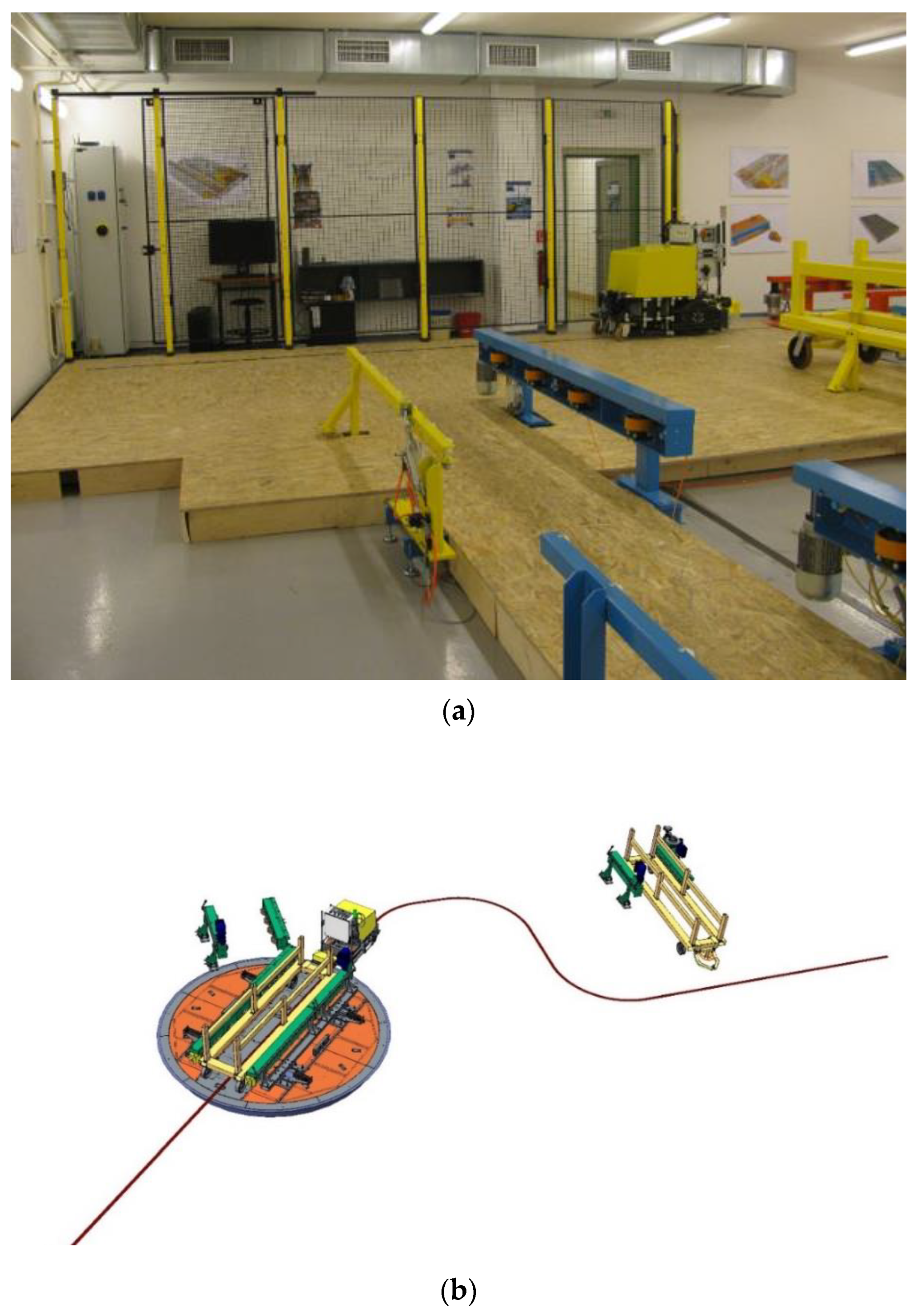
  • MRS (mobile robotic system): A bi-directional, real-world hardware prototype capable of transporting parts of an MML. It is bounded by the limited processing capacity and memory and it uses infrared optical sensors that allow it to be guided by a black tape [10].
  • MRSA (mobile robotic system agent): A virtual entity mirroring its MRS. It provides transport services for modular platform agents. All decisions and interactions with other agents are made by the MRSA. The final decisions are encoded and sent to its MRS.
  • MP (modular platform): A physical part of an MML that is able to connect to (or disconnect from) other modular platforms. It hosts a superstructure that can be a manufacturing or a logistic resource (robotic arm, conveyor, etc.). Superstructures and their agents are beyond the scope of this paper.
  • MPA (modular platform agent): Reflects an MP in the virtual environment. It uses the transport services of the MRSA (Figure 1).
  • CA (crossroad agent): Provides reservation services for an MRS’s passage through its real-world counterpart.
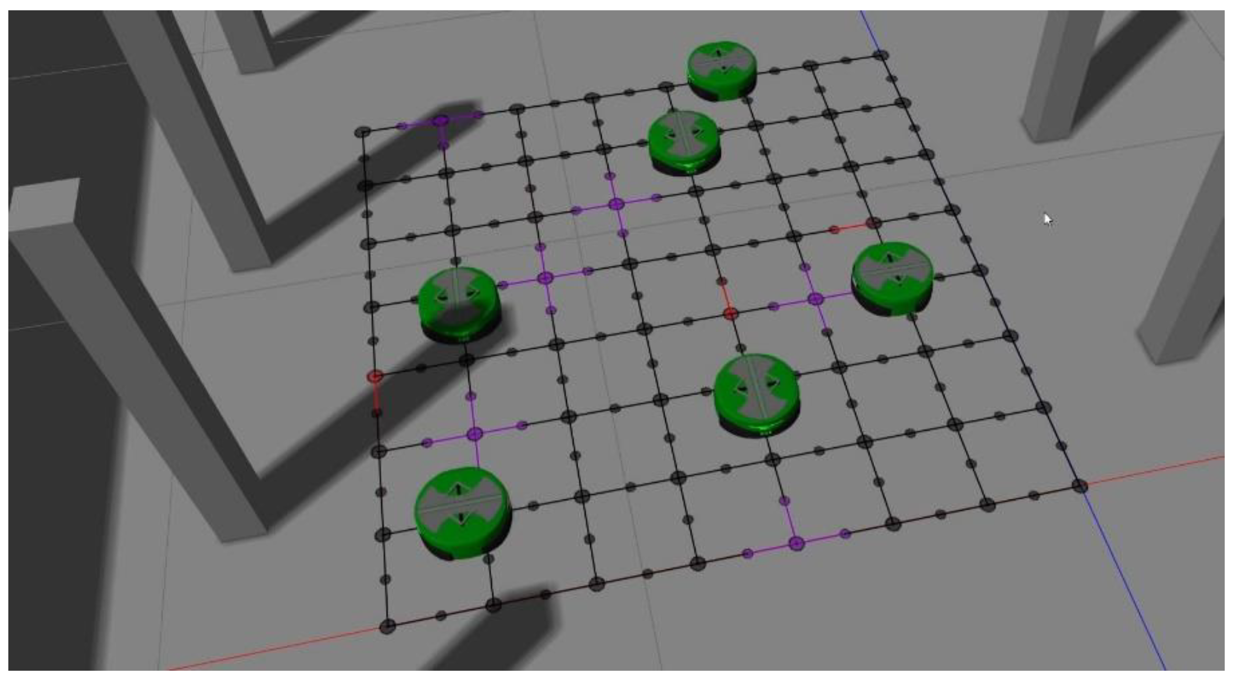
  • GG (guidance grid): Composed of all crossroads (Figure 2). Note that the size of the crossroad is about the size of an MPA. This allows an MPA to connect to other MPAs when it is located at the center of a crossroad.
Figure 3 illustrates an artistic vision of our application.
There are several advantages to our approach:
  • Production capacities can easily be expanded (by adding more modules);
  • The system can respond to fluctuating demand (by removing some modules);
  • Re-routing of the material flow is simple;
  • Modules that are out of order can easily be replaced;
  • Start-up times and costs are reduced;
  • The system can be dismantled and relocated to another factory.
A video that shows by us developing Modular Manufacturing Line with all his components can be seen in Supplementary Materials part as Video S1.
The subject of the next chapter is the definition of the objective, targets, and goals. The chapter contains constraints, formulated requirements, a justification of the selection of D-MAS, and a description of research and limitations.

Objective, Targets, and Goals

The application we have hereinbefore described, requires a continuous, decentralized route planner, suitable for being used in a dynamic environment. Decentralized solutions, such as MAS, can outperform centralized planners, if the application has the following properties: high urgency, medium to high dynamism, and medium to large scale [11].
There are several constraints restricting the use of a route planner in our application:
  • The planning must be highly urgent, in order to meet the requirements of an MML’s reconfiguration.
  • The environment must be highly dynamic due to the possible delays or breakdowns of the hardware prototypes, and adding or removing agents.
  • The application requires a continuous planner because new transport orders can be requested at any time.
  • An MRS is bounded by the limited processing capacity and memory and it does not possess a sensor for detecting obstacles or other MRSs.
  • Movement restrictions resulting from the fact that hardware prototypes physically occupy space.
  • The presence of deadlock and live-lock situations.
We have formulated five requirements (R1–R5) that the route planner should satisfy. It should be able to:
  • R1: deal with the highly urgent, space-constrained application and minimize the processing resources.
  • R2: deal with the movement restrictions of MRS and at the same time to be live-lock and deadlock-free.
  • R3: cope with the dynamism of the real-world environment (variable velocity of the agents; disturbances, changes, delays, and breakdowns of the agents; and communication failures)
  • R4: minimize unnecessarily traveled distances and the travel times of the MRSs, and to maximize the throughput of the GG.
  • R5: be scalable and leave room for further improvements and changes.
We chose a decentralized route planner using delegate multi-agent systems (D-MAS) in order to meet R1, R3, and R5. Decentralized planners seem to be comparable to centralized state-of-the-art planners in some cases, yet still offer a decentralized approach without the need of access to global knowledge [7]. A proper implementation of the D-MASs leaves room for further improvements.
The routing problem of the kind we describe has been shown to be at least NP-hard [12]. On the other hand, in a D-MAS, the complexity of computations and communication is low-polynomial [13].
The formulation of the requirements R1–R5 sums up the problem definition and their fulfillment can be considered the novelty of this paper.
In research, we selected D-MAS because we had a good experience with the application of D-MAS in a previous research project, and at the same time, we did not have experience with commonly used pathfinding algorithms. The implementation of D-MAS provided larger room for changes and the needs of our modular manufacturing line. The first need was the reservation of a time interval in consideration of the nondiscrete movement of an MRS. Most pathfinding algorithms are used for discrete movement.
Infinity intention pheromone (IIP) algorithm: the next need was the possibility of collecting additional data from the environment through D-MAS (if the MRS starts moving on a single road in a short time).
The last most important need was that, unlike most of MAS pathfinding algorithms, ours had to guarantee that the MRS (agent) reaches its object even if the path to the object does not exist (Windowed Hierarchical Cooperative A *—WHCA *) [14].
The limitation of this approach is that this can be applied on a small number of crossroads on the map, with small number of AGVs, and with the statement that an AGV always reaches its object.
The article discussed part of research which is aimed at increasing the competitiveness of enterprises thanks to modular manufacturing lines. Main projects aim at logistics, capacity calculations, planning, and control, or overall, at applicability and feasibility. Proof-of-concept continues to a fully functional prototype. Part of this research was also used in a project where an innovative logistics system, based on the modular principle, was created. In this project we successfully applied D-MAS for the coordination and control of a one-way, tape-guided AGV [15] (Figure 4).
The next chapter deals with material and methods. The chapter discusses delegate-MASs, the design method, the graph structured network (GSN), MRSA, and CA as the primary agents, and the ants’ applications.

2. Materials and Methods

2.1. Delegate-MASs

Primary agents (the application level agents, which can represent, e.g., manufacturing or logistic resources, products, and orders), need to interact with other primary agents to ensure coordination and synchronization among them [16]. There are two types of communication that primary agents can use: direct and indirect communication.
Direct communication, such as exchanging messages can lead to complex and largely unpredictable behavior of agents, given the large number of conversations in which they can be involved [16]. One of the indirect kinds of interaction is pheromone-based communication. A pheromone is a data structure that evaporates over time. In other words, the intensity of the pheromone, and thus the validity of any information it holds, decays over time.
Primary agents use behavioral modules called D-MASs that reduce the agents’ internal structural complexity [9]. Such D-MASs consist of mobile, lightweight agents (called ants—after their biological inspiration). Ants serve as delegates and perform specific, assigned tasks. They can gather information and disseminate pheromones in the environment, thus they can interact with remotely-located primary agents. Their behavior, memory, and processing resources are limited; thus, they are computationally efficient [17]. Ants move and execute tasks much faster than their primary agents (or agents’ counterparts in the real world). In other words, they can travel through space and time into the future and find alternative behaviors for their primary agents.
There are two types of primary agents. (1) The resource agent (RA) (e.g., manufacturing resources) provides services to (2) the task agent (TA) (e.g., work-in-progress instances of products). The TAs, usually considered as mobile agents, can travel through the environment and consume the services offered [16]. The RAs should maintain up-to-date information concerning how their services are allocated among the TAs. This information will the form a schedule [18]. The TAs are responsible for task control and execution.
The TAs and ants can travel through the environment, which is represented by a graph also called the graph structured network (GSN) [16] which is used by the coordination mechanisms (dissemination of information and resource allocation)) [17]. A GSN is composed of vertices (nodes) and edges (segments). Nodes represent RAs and segments represent bi-directional communication links to the neighboring RAs, over which the TAs and the ants can travel and interact [19]. A GSN can be static e.g., a network of routes or dynamic, in which case changes/failures of nodes or communication links can occur [20]. However, it should be noted that there are several cases [21,22] in which the links provide services (e.g., passages).
Nodes in the GSN have a specific infrastructure that stores pheromones, called the pheromone infrastructure. It may include the pheromone evaporation function and may provide an interface for primary agents and ants to deposit (i.e., drop), observe (i.e., smell), modify, or refresh pheromones.
In general, there are three basic types of the D-MASs [23]. Each of them offers a different service:
  • Feasibility ants;
  • Exploration ants;
  • Intention ants.
Feasibility ants (FAs) are deployed at the location of their RA (at the node it resides on). Their task is to roam the GSN and disseminate feasibility information about their RA. They can aggregate information (e.g., capabilities or already-allocated capacities) from other RAs with existing information. The feasibility pheromone is dropped into every node an FA encounters, and it may contain a digital road sign directed to the node from which an ant arrives [16,23,24]. The use of the FAs is more or less optional.
Exploration ants (EA) are created at the location of their TA. Their task is to find a feasible routing (path) through all the necessary resources (i.e., RAs). They can virtually execute the services provided by the Ras; thus, testing various alternative behaviors for a TA (Philips et al., 2013). Every RA an EA encounters is asked a “what-if” question; e.g., what the timing, distance, quality or costs would be if a TA would arrive in a particular state at the particular moment in time. The answer is aggregated with already-gathered information [25]. When the task is completed (or canceled), an EA returns to its TA using the same path. The TA then selects the suitable path and makes a commitment to it; therefore, it creates an intention. The periodic deployment of the EAs can lead to the discovery of new solutions, or to the detection of new disturbances in the environment. In some cases [22], EAs drop road sign pheromones to guide their TAs.
When a path is selected and a commitment is made, a TA deploys an intention ant (IA). An IA informs all RAs in the selected path about the future allocation of its TA [17]. In other words, the IA reserves all necessary capacities. Reservations allow the generation of a short-term forecast of the future spacetime movement of the TAs, possible future workloads of the Ras, and a forecast of the system’s behavior. After successful (or unsuccessful) task execution, an IA returns to its TA. Evaporating and refreshing of the pheromones allows the system to forget invalid solutions, thus the system is able to cope with changes and disturbances [26,27].

2.2. Design Method

Due to limited processing and communication resources of the MRSs, all the coordination and control mechanisms were implemented in the centralized, virtual, shared environment. The disadvantages of creating such an environment are constrained scalability, and reduced fault tolerance and robustness [23].

2.3. Graph Structured Network (GSN)

The GSN is formed by nodes and segments. Nodes can be divided into two groups: (1) Physical nodes (also called crossroad nodes) that are the centers of the crossroads. In the MAS, a crossroad is represented by a primary agent—the crossroad agent (CA), and can be composed of two to four virtual segments; see Figure 5. These are connected to the physical node. (2) Virtual nodes are not part of any crossroad; they just represent boundaries of the crossroads. Just as the virtual segments, they are present only in the virtual environment. Each node has its own ID and it is aware of the neighboring nodes. A set of IDs is an abstraction of an MRSA’s route.
There are three types of segments (Figure 5):
  • Virtual;
  • Physical;
  • Logical.

2.4. MRSAs and CAs as the Primary Agents

The CAs represent a specific type of an RA, which provides services in the form of passage to the MRSAs. An MRSA is both a TA and an RA. They are mobile; they search for a route consisting of services, using exploration and intention D-MASs. As RAs, they provide transportation for MPAs.
An MRS does not possess any sensors to detect other MRSs, and thus, it cannot avoid collisions by itself (R2). With its optical sensors, it can only reliably evaluate its presence at a physical node (i.e., a center of a crossroad).
An MRSA (and its counterpart MRS), when it is situated at a crossroad, occupies almost its entire area (including its virtual segments). Therefore, a CA can only be reserved by one MRSA at a given time. The problem occurs when an MRSA is moving. Its position between two physical nodes is unknown. Thus, an MRSA needs valid reservations at both CAs while moving between them.
A reservation of an MRSA can be cleared once the next physical node has been successfully identified by the MRS. When two consecutive CAs (including their virtual segments) are reserved, they form a logical segment; see Figure 5. Only one MRSA per logical segment is allowed. The segment between two physical nodes is called a physical segment; see Figure 5. A physical segment is divided into two virtual segments by a virtual node. The logical segment, unlike the physical segment, includes all virtual segments of both crossroads. The physical segment defines the time interval that needs to be reserved for a passage at a given velocity.
Thus, a logical segment can, at a given time, be reserved by only one MRS. This is the first coordination rule, CR1, and it addresses R2. The reservations themselves address R4.
An MRSA needs to activate a reservation on the following crossroad in order to enter it. There are four types of activation; see Figure 6:
  • A: Starting activation. At the beginning of the simulation or after the addition of an MRSA to the virtual reality, an MRSA activates the reservation of the crossroads it resides on.
  • B: “Hit the road” activation. Just before an MRSA leaves its first crossroad, it tries to activate the reservation at the second crossroad of its route.
  • C: Forward activation. If moving, an MRSA will continue straight ahead after the next crossroad (i.e., it is not stopping or turning); it tries to activate the reservation of the crossroad that is the second one in the order. This activation is performed on a virtual node.
  • D: Turning activation. If the moving MRSA will turn (left or right) at the next crossroad, it tries to activate the reservation of a crossroad that is the second in the order. In that case, the activation is performed after the turning.
Deactivation of an activated reservation is performed after an MRS (in the virtual reality an MRSA) successfully arrives at the following crossroad. Because of the disturbances (MRS delays, loss of communication link, etc.), the arrival may not happen. In the case of activated reservations, intention pheromones (IPs) do not evaporate and they cannot be erased. If an MRS does not receive a message from MRSA that authorizes entering the second crossroad in the list, it simply stops at the next one (with the already-activated reservation). The active reservation prevents other MRSAs from entering the occupied crossroad. If an activation of a reservation fails, an MRSA will force its counterpart to stop. If there is a breakdown of an MRS (for simplicity, imagine discharged batteries), the MRS will stop somewhere between the crossroads; both crossroads stay reserved in the virtual reality.

2.5. Ants

Ant agents with the same behavior originating from one deployment (and their clones) have their own IDs (ACIDs); see Figure 7. An ACID guarantees its uniqueness during the whole system’s lifetime.
To re-address R1, an ant at the end of its life cycle (after the successful or unsuccessful completion of its task), does not travel back to its agent. To save valuable time and processing resources, the ant returns to its agent via an underlying communication channel, as a direct message. The agents and ants have a number of tickets, which defines the maximum number of clones that can be made. In this manner, a primary agent can track the number of the ants that are still active and does not have to wait for some kind of deadline. Their life cycle can also be limited by the maximum number of hops—the number of jumps from one physical node to another.

2.5.1. Feasibility D-MAS

The FAs were implemented to reduce the usage of processing resources and time, to partially cope with R1 and to minimize unnecessarily traveled distances and time, so as to address R4. They facilitate the search of the EAs for an optimal route.
A CA’s feasibility D-MASs module is initialized at MRSA’s request via a direct message. To re-address R1, the module of each CA is executed only once, considering the static positions of the CAs and their real-world counterparts. Feasibility pheromones do not evaporate (thus, we may rather use the term feasibility information). Feasibility information (FI) exists in the GSN during the lifetime of the system. Before an MRSA deploys the EAs, it tries to find an FI originating in the MRSA’s destination. If there is no FI deployed by the destination CA, an MRSA requests the CA to deploy FAs by a direct message. Such one-shot deployment of the FAs for each crossroad, and the persistence of the FI, reduce the time and the usage of processing resources.
The task of the FAs is to spread FI about its CA to all other CAs. Each FI contains a road sign with the ID of the physical node from which an ant arrived and the cost (composed of the aggregated time and distance) of its traveled route. When an FA is deployed, it clones itself and the clones are placed at all possible virtual nodes. During their journey, their clones are placed at all virtual nodes, except the node they came from. The life cycle of an FA ends, when FI is already dropped at the node and contains a lower cost. The use of the FAs reduces the number of EAs that are required, as well as their complexity.
Each physical node (in the virtual environment) contains a pheromone structure called the pheromone container (PhC). The structure is managed by the CA. PhC holds the IPs and the FI. It also contains a function that ensures the evaporation of the IPs.
In order to re-address R1, a data structure that holds FI was implemented as a binary search tree (BST); see Figure 8. The main advantage of the BST is the fast look-up (O (log n) time complexity on average), addition, and removal of items.
The key values in the feasibility BST are represented by the names of the CAs, which own the FI. The values of the BST consist of the FI, and they may contain up to four “pairs of road signs and costs” (PsRC). When dropping the FI, the FA inserts the number of the hops traveled into it.

2.5.2. Exploration D-MAS

To re-address R1, the search for a route to a destination node (i.e., a CA) is executed only at the beginning of the MRSA’s journey. MRSA does not change its intention during its journey. This is called simple, naive strategy [28] or blind commitment [16]. An agent using blind commitment is not able to cope with the dynamics in the environment [29]. However, the commitments of agents in our application last from seconds to one minute. Thus, blind commitment does not have any great impact in our application. Yet, we have tried to implement the possibility of changing the commitment during the agent’s trip. That resulted in the loss of the lightweight properties of the ants—not to mention the increased complexity of the MRSA class. The effort to reduce the communication bandwidth from MRSA to MRS also played its role.
The task of an EA is to find the path with the lowest cost to the destination node. An EA stores the IDs of nodes through which it has passed. The cost of the path traveled by an EA is defined as:
crEA = w1 lrEA + wt tMRSA
where crEA is the cost of the path traveled by the EA, wl is the weight per element of length, lrEA is the length of the path traveled by the EA, wt is the weight per element of time, and tMRSA is the time for which an MRSA would travel the selected path.
Ants are cloned based on FI. Unused tickets are passed to the cloned ants. An ant terminates its life cycle right after the cloning. It then reports the number of used and unused tickets. When an ant runs out of its tickets, it can continue on its journey, until it runs out of hops. The number of clones at a physical node is determined by the number of PsRC that are present in the feasibility information. An ant-template passes tickets to ant-clones based on the cost ratio:
t1 = nt + ri
where ti is the number of tickets for an ant I, nt is the total number of tickets, and ri is the cost ratio for ant I, in which:
r i =   c t c i 1 n c t c i
where ct is the total sum of the costs in a feasibility pheromone, ci is the cost for ant I, and n is the number of cloned ants (or PsRC), for which:
i = 0 n c i
An MRSA maintains the list of the three least-cost routes. If an IA fails, it will try to reserve the next route in the list. An IA has less performance impact than the EAs. If the reservation of the third route fails, an MRSA will multiply the default number of tickets by the number of unsuccessful attempts of searching, and it repeats the search. This allows an MRSA to find other possible routes to the destination. After a successful reservation of the route, an MRSA resets the number of tickets to the default value.
The number of hops is determined by the FI present at the local PhC. However, this is the optimal number. The optimal route may not always be feasible. Thus, there is the option to add further hops.
An EA, instead of asking a what if question, performs a test (a virtual drop) at all CAs it encounters, testing whether there is a free time interval for a future IP. For the sake of simplicity and to ensure that the testing time interval for the future reservation will match the actual future reservation, the same mechanisms for EAs and IAs were implemented. The only difference is that during the reservation test, pheromones were not dropped. This approach saved us from a lot of bug fixes.
An EA accumulates the traveled distances and the time that it would take an MRSA to travel it. The accumulation of the distances is an easy task, considering that all physical segments are of the same length (0.22 cm). However, with the accumulation of the times, things get a bit more complex. Considering the limited ability of the MRS to determine its position, a logical segment needs to be reserved for the whole time that an MRSA is traveling through it (CR1). Thus, both CAs (being parts of the logical segment) need to be reserved, in order to fulfill that. However, the times may vary depending on the action the MRSA takes at the second CA of the logical segment. If the MRSA stops or slows down and turns, this will naturally take more time than if it continues straight ahead without slowing down at all. The time is known after an EA agent is cloned at the second CA and it knows the direction in which it will continue. Thus, an EA needs to return to the first part of the logical segment and test the reservation, now possessing the knowledge of what its behavior will be, once it passes the second part of the logical segment. The list of the possible MRSA’s pairs of itinerary actions per logical segment (e.g., continue straight at the first crossroad and stop at the second crossroad) is:
  • Start and stop;
  • Continue and continue;
  • Start and continue;
  • Continue and stop.
There are also actions that can be performed at a single crossroad:
  • Turn right;
  • Turn left;
  • Switch direction;
  • Emergency stop.
Figure 9 depicts an example of one possible itinerary. The itinerary comprises actions that the MRS needs to perform at each crossroad. The MRS is obligated to report the crossing of each crossroad so that the MRSA can monitor its movement.

2.5.3. Intention D-MAS

A route needs to be reserved to the destination; we materialized thats requirement in the form of coordination rule CR2, so as to cope with requirement R2, and reduce the possibility of deadlocks or live-locks. CR2 also addresses requirement.
R4, minimizing unnecessarily traveled distance and travel time of MRS and maximizing the throughput of the GG.
There is no time in which a new path is guaranteed to be found. To solve this issue, we propose the infinity intention pheromone (IIP) (or infinity reservation). The IIP contains the start date, but the end date is denoted as infinity. An IIP must be dropped by an IA at its destination (coordination rule CR3) to indicate this uncertainty. It is removed, when an MRSA reaches its destination and finds a new route (if there is another transport order).
To address R3, there is a need for a forced infinity intention pheromone (FIIP). If an MRSA is forced to stop, it will drop an FIIP at the next crossroad. The FIIP will erase all reservations that overlap with the FIIP (coordination rule CR4). Note, however, that the MRSA still needs a valid reservation to drop the FIIP.
During its journey, an MRSA refreshes IPs in its path. Such refreshing ensures that the path remains reserved during the whole journey, and it can also detect erased reservations. Considering the possible delays of the MRSAs, some reserve time can be added at the start and at the end of the reservation.
Iterating through all IPs and testing whether dropping a new pheromone does not overlap with the already-dropped pheromones, are compute-intensive tasks. To re-address R1, we used the BST (see Figure 10) as the data structure that held the IPs as well. The keys of the BST, the dates and the values of the BST, are (index, pheromone) pairs. Dates labeled with an even index define the start of a reservation and dates with an odd index define the end of a reservation. The BST provides temporary indexes when a pheromone is about to be dropped and compares them with the existing ones. If no overlap rules are violated (e.g., in some cases index values may vary only by one), the IPP is dropped. Thus, we avoid iteration through the pheromones. The only drawback of this approach is the need to refresh the indexes after each successful drop.
An IA is not cloned. It just follows the path that consists of IDs and uses the same reservation mechanisms as the EAs. After a successful reservation of the selected path, the IA reports back to its MRSA.
The evaporation rate of the IPs depends on the deployment period:
evr ph   =   1 T d   [ s 1 ]
where evrph is the evaporation rate of the IP, and Td is the period of the deployment cycle.
The next chapter describes a proof-of-concept implementation and results.

3. Results

A Proof-of-Concept Implementation

The design method of our route planner was verified in the virtual 3D environment, called Ella Software Platform (ESP) [30], to better understand the characteristics and the issues of the planner. The ESP provides the proper tools for the implementation, such as a discrete world, 3D graphics, a physics engine, an MAS module, etc. We performed experiments on a machine with the Intel Core i7 6700HQ 2.60 GHz processors. ESP can only use one physical thread. The static size of the GSN was 8 × 8, and thus there were 64 crossroads see Figure 11.
We evaluated two approaches: (a) with reservations (WRA) and (b) without reservations (NRA).
In the approach without reservations (NRA), there are no reservations; however, there are occupations; i.e., the presence of an MRSA at the crossroad. If the next-in-the-list crossroad is occupied, an MRSA stops at the current crossroad and it starts searching for a new route to the destination. However, we needed to implement a simple resolution for a temporal live-lock. The live-lock occurs when two MRSAs try to swap their positions at the neighboring nodes. If an MRSA detects a live-lock, it uses the third found route in its route list (the choice of the second route occasionally led to another live-lock). In this case, the EAs do not test for reservations. In order to increase the throughput of the GSN, they instead check the occupancy of the first crossroad after their deployment. If the crossroad is occupied, the ant reports an unsuccessful execution of the task.
For each approach, we used from one to six MRSAs. Each MRSA had to visit ten different destinations (but the destinations were the same for both approaches). Both reserve times (starting and ending) of the reservation intervals were set to 0.3 s. The deployment period was set to 2.0 s. The default number of tickets was set to 10.
At the time of writing, there were no measured time characteristics of the MRSs. Table 1 contains the arbitrary durations that were chosen for each itinerary action. The variable velocity of the MRSA was implemented as the function of time.
Table 2 and Table 3 contain the average and the longest (i.e., the worst) travel time of each D-MAS in the approach with reservations (WRA) and the NRA. The resulting time was influenced by the length of the route and the overall number of agents (1–6) and ants in the environment.
The average number of the FAs located in the environment at the same time was 166.1, and the maximum number was 283 per deployment. The average number of FAs per deployment was 1050.1, and the maximum number of the FAs was 1901 per deployment.
Figure 12 shows the average of the optimal total times (i.e., reservations not taken into account), which is the same for both approaches; the average of the best total times found by the EAs in the WRA (i.e., taking into account the reservations); and the average of the total travel times for both approaches. The average times are given per one MRSA, taking into account all ten pre-defined routes. There was no point in measuring the best total time found by the EAs under the NRA, as the EAs were deployed several times during the trip.
The EAs under the WRA were deployed only once, at the beginning of the trip. Each MRSA eventually reached its destination.
Figure 13 shows similar results, but with the average measured distances. We can conclude the same: the WRA outperforms the NRA as the number of MRSAs increases. In the case of the WRA, the average of the total distances traveled was identical to the average of the distances found by the EAs.
Another perspective that we can examine is a comparison of two states: the average amount of waiting and the average amount of moving per one MRS, considering all ten pre-defined routes. This perspective can be expressed by the duration of the transport orders. Figure 14 and Figure 15 show the duration of those states for the NRA and the WRA, respectively.
The more MRSAs there are in the environment, the longer it takes to find and reserve a new route. However, similarly to the previous cases, as the number of MRSAs increases, the movement and the total durations are shorter; thus, the WRA outperforms the NRA. The usage of reservations increases the throughput of the GSN.

4. Discussion

The average times of the FAs are comparable for both approaches, but in the NRA, the EAs were slightly faster because they did not test for reservations.
Starting with one MRSA, the total time found by the EAs was identical to the optimal total time. This makes sense because there were no foreign reservations. However, the total travel times in both approaches were longer because they also included the time of searching, and in the case of the WRA, the time also included the travel time of the IAs; but the difference was not significant. The change occurred with the presence of three MRSAs in the environment, resulting in a more time-consuming performance of the NRA. In the case of the WRA, the more MRSs there are in the environment, the longer it takes to find and reserve a new route. But the total travel time under the WRA was shorter than the total travel time under the NRA. In the case of the NRA, on the contrary, the more MRSs there are in the environment, the more often they stop and the longer they wander. We can conclude that, as the number of MRSs increases, the WRA outperforms the NRA in the total travel time.
The waiting duration is longer under the WRA. This can be explained by the fact that under the WRA, the MRSAs cannot leave their positions until the whole route is reserved; thus, they are waiting.
We have proposed a design method and formulated several coordination rules, for this type of planner. The route planner was compared to a different, non-reservation-based approach. We tested the approaches in 3D virtual reality, so as to better understand their properties and identify errors.
Experiments show that as the number of MRSAs increases, our approach achieves better performance regarding the travel times, distances traveled, and the time of transport-order execution. Thus, a proof-of-concept solution has been achieved.
From our experience of implementing this type of planner, we can formulate several recommendations. The more urgent a system is, the more complex the agents and ants are: hence they are becoming less lightweight. We recommend using similar or identical mechanisms for testing of the reservations by the exploration ants, and making reservations by the intention ants. That will prevent programmers from introducing numerous bugs into the code base, and will make the code easier to maintain. If a task can be delegated to the intention ants instead of the exploration ants, the intention ants should be preferred for performance reasons.

5. Conclusions

The paper describes the use of delegate MAS for route planning in a time-constrained and space-limited environment. Its novelty lies in the combination of the following requirements imposed on the planner:
  • To deal with a highly urgent, space-constrained application, and minimize processing resources;
  • To deal with the movement restrictions of MRS, and at the same time, to be live-lock and deadlock-free;
  • To cope with the dynamism of real-world environments (variable velocity of the agents; disturbances, changes, delays, and breakdowns of the agents; and communication failure);
  • To minimize unnecessarily traveled distances and the travel times of the MRSs, and to maximize the throughput of the GG;
  • To be scalable and leave room for further improvements and changes.
Our next steps will lead to a real-world application of the developed system and to coordination and control of real-world hardware prototypes. The route planner will be used for coordination and control of mobile agents that transport parts of the modular lines.

Supplementary Materials

Link on a video that shows Modular Manufacturing Line developing by us as Video S1 is available online at: https://www.youtube.com/watch?v=_eZjx5m5rNs.

Author Contributions

All authors contributed to writing the paper, documenting the literature review, analyzing the data, and writing the paper. All authors were involved in the finalization of the submitted manuscript. All authors read and approved the final manuscript.

Funding

This work was supported by the Slovak Research and Development Agency under the Contract no. APVV-18-0522.

Conflicts of Interest

The authors declare no conflict of interest.

Abbreviations

BSTBinary Search Tree
CACrossroad Agent
D-MASDelegate MAS
EAExploration Ant
ESPElla Software Platform
FAFeasibility Ant
FIFeasibility information
FIIPForced Infinity Intention Pheromone
GGGuidance Grid
GSNGraph Structure Network
IAIntention Ant
IIPInfinity Intention Pheromone
IPIntention Pheromone
MASMulti-Agent System
MMLModular Manufacturing Line
MPModular Platform
MPAModular Platform Agent
MRSMobile Robotic System
MRSAMobile Robotic System Agent
NRAApproach Without Reservations
PhCPheromone Container
PsRCPairs of Road signs and Costs
RAResource Agent
TATask Agent
WRAApproach With Reservations

References

  1. Haluska, M.; Gregor, M. Concept of the system for design and optimization of configurations in new generation of manufacturing systems. Int. J. Manag. Soc. Sci. Res. Rev. 2016, 1, 181–184. [Google Scholar]
  2. Micieta, B.; Markovic, J.; Binasova, V. Advances in sustainable energy efficient manufacturing systém. MM Sci. 2016, 2016, 918–926. [Google Scholar] [CrossRef]
  3. Wooldridge, M.J. An Introduction to Multiagent Systems, 2nd ed.; John Wiley Sons: Chichester, UK, 2009. [Google Scholar]
  4. Leitao, P.; Karnouskos, S.; Ribeiro, L.; Lee, J.; Strasser, T.; Colombo, A.W. Smart Agents in Industrial Cyber–Physical Systems. Proc. IEEE 2016, 104, 1086–1101. [Google Scholar] [CrossRef]
  5. Suzuki, J.; Suda, T. Design and Implementation of a Scalable Infrastructure for Autonomous Adaptive Agents. In Proceedings of the 15th 1asted Internacional Conference Parallel and Distributed Computing and Systems, Marina Del Rey, CA, USA, 3–5 November 2003. [Google Scholar]
  6. Karnouskos, S.; Leitao, P. Key Contributing Factors to the Acceptance of Agents in Industrial Environments. IEEE Trans. Ind. Inf. 2017, 13, 696–703. [Google Scholar] [CrossRef]
  7. Dinh, H.T.; van Lon, R.; Holvoet, T. Multi-agent route planning using delegate mas. In Workshop on Distributed and Multi-Agent Planning; London, UK, 2016; pp. 24–32. [Google Scholar]
  8. Huard, E.; Gorissen, D.; Holvoet, T. Applying Delegate Multi-Agent Systems in a Traffic Control System CW ReportsCW Reports; Katholieke Universiteit Leuven: Leuven, Belgium, 2006. [Google Scholar]
  9. Holvoet, T.; Valckenaers, P. Exploiting the Environment for Coordinating Agent Intentions. In Environments for Multi-Agent Systems III; Weyns, D., Parunak, H.V.D., Michel, F., Eds.; Springer: Berlin/Heidelberg, Berlin, 2007; Volume 4389, pp. 51–66. [Google Scholar] [CrossRef]
  10. Patka, J.; Gregor, T.; Gregor, M. The architecture of smart connected mobile robotic systems. In Invent 2016: Industrial Engineering-toward the Smart Industry; University of Zilina: Žilina, Slovakia; EDIS: London, UK, 2016; Volume 11, pp. 132–135. [Google Scholar]
  11. van Lon, R.R.S.; Holvoet, T. When Do Agents Outperform Centralized Algorithms? A Systematic Empirical Evaluation in Logistics. Auton. Agent. Multi-Agent Syst. 2017, 31, 1578–1609. [Google Scholar] [CrossRef]
  12. Philips, J.; Valckenaers, P.; Bruyninckx, H.; Van Brussel, H. Scalable and Robust Coordination of Multiple Mobile Robots Using PROSA and Delegate MAS. In Proceedings of the International Symposium on Robotics (ISR), Taipei, Taiwan, 29–31 August 2012; pp. 527–532. [Google Scholar]
  13. Rutten, L.; Valckenaers, P. Self-Organizing Prediction in Smart Grids through Delegate Multi-Agent Systems. In Trends in Practical Applications of Agents and Multiagent Systems; Pérez, J.B., Rodríguez, J.M.C., Fähndrich, J., Mathieu, P., Campbell, A., Suarez-Figueroa, M.C., Ortega, A., Adam, E., Navarro, E., Hermoso, R., et al., Eds.; Springer International Publishing: Cham, Swtherland, 2013; Volume 221, pp. 95–102. [Google Scholar]
  14. Silver, D. Cooperative Pathfinding. In Proceedings of the AIIDE’05 First AAAI Conference on Artificial Intelligence and Interactive Digital Entertainment, Marina Del Rey, CA, USA, 1–3 June 2005; pp. 117–122. [Google Scholar]
  15. Vavrík, V.; Gregor, M.; Grznár, P. Optimalizačné metódy vyvažovania. In Proceedings of the InvEnt 2018: Industrial Engineering-Invention for Enterprise 2nd Edition-Žilina CEIT Stredoeurópsky technologický inštitút, Banka Žilina, Žilina, Slovakia, 14–15 June 2018; pp. 132–135, ISBN 978-80-89865-07-9. [Google Scholar]
  16. Holvoet, T.; Weyns, D.; Valckenaers, P. Patterns of Delegate MAS. In Proceedings of the 2009 Third IEEE International Conference on Self-Adaptive and Self-Organizing Systems, San Francisco, CA, USA, 14–18 September 2009; IEEE: San Francisco, CA, USA, 2009; pp. 1–9. [Google Scholar] [CrossRef] [Green Version]
  17. Belle, J.V.; Germain, B.S.; Philips, J.; Valckenaers, P.; Cattrysse, D. Cooperation between a Holonic Logistics Execution System and a Vehicle Routing Scheduling System. IFAC Proc. Vol. 2013, 46, 41–46. [Google Scholar] [CrossRef]
  18. Van Belle, J. A Holonic Logistics Execution System for Cross-docking (een holonisch logistiek uitvoeringssysteem voor cross-docking); KU Leuven: Leuven, Belgium, 2013; ISBN 978-94-6018-749-0. [Google Scholar]
  19. Verstraete, P.; Valckenaers, P.; Van Brussel, H.; Saint Germain, B.; Hadeli, K.; Van Belle, J. Towards Robust and Efficient Planning Execution. Eng. Appl. Artif. Intell. 2008, 21, 304–314. [Google Scholar] [CrossRef]
  20. Holvoet, T.; Weyns, D.; Valckenaers, P. Delegate MAS Patterns for Large-Scale Distributed Coordination and Control Applications. In Proceedings of the 15th European Conference on Pattern Languages of Programs-EuroPLoP ’10; ACM Press: Irsee, Germany, 2010; p. 1. [Google Scholar] [CrossRef]
  21. Weyns, D.; Holvoet, T.; Helleboogh, A. Anticipatory Vehicle Routing Using Delegate Multi-Agent Systems. In 2007 IEEE Intelligent Transportation Systems Conference; IEEE: Bellevue, WA, USA, 2007; pp. 87–93. [Google Scholar] [CrossRef]
  22. Philips, J.; Germain, B.S.; Van Belle, J.; Valckenaers, P. Computational Complexity and Scalability Analysis of PROSA and Delegate MAS. IFAC Proc. Vol. 2013, 46, 29–34. [Google Scholar] [CrossRef]
  23. Holvoet, T.; Valckenaers, P. Beliefs, Desires and Intentions through the Environment. In Proceedings of the fifth International Joint Conference on Autonomous Agents and Multiagent Systems -AAMAS ’06, Hakodate, Japan, 8–12 May 2006; ACM Press: Hakodate, Japan, 2006; p. 1052. [Google Scholar] [CrossRef]
  24. Hadeli Valckenaers, P.; Van Brussel, H.; Verstraete, P.; Germain, B.S.; Van Belle, J. Production Planning and control in bio-inspired holonic manufacturing execution systems. IFAC Proc. Vol. 2007, 40, 42–49. [Google Scholar] [CrossRef]
  25. Van Dyke Parunak, H.; Brueckner, S.; Weyns, D.; Holvoet, T.; Verstraete, P.; Valckenaers, P.E. Pluribus Unum: Polyagent and Delegate MAS Architectures. In Multi-Agent-Based Simulation VIII; Antunes, L., Paolucci, M., Norling, E., Eds.; Springer: Berlin/Heidelberg, Germany, 2008; Volume 5003, pp. 36–51. [Google Scholar] [CrossRef]
  26. Valckenaers, P.; Saint Germain, B.; Verstraete, P.; Van Brussel, H. MAS Coordination and Control Based on Stigmergy. Comput. Ind. 2007, 58, 621–629. [Google Scholar] [CrossRef]
  27. Claes, R.; Holvoet, T. Maintaining a distributed symbiotic relationship using delegate multiagent systems. In Proceedings of the 2010 winter, Simulation conference (wsc), Baltimore, MD, USA, 5–8 December 2010; pp. 2981–2990. [Google Scholar]
  28. Varga, L.Z. A Game Theory Model for Self-Adapting Traffic Flows with Autonomous Navigation. In Autonomic Road Transport Support Systems; McCluskey, T.L., Kotsialos, A., Müller, J.P., Klügl, F., Rana, O., Schumann, R., Eds.; Springer International Publishing: Cham, Swtherlands, 2016; pp. 13–28. [Google Scholar] [CrossRef]
  29. Vandael, S.; Holvoet, T.; Deconinck, G. A decentralized approach for public fast charging of electric vehicles using delegate multi-agent systems. In Proceedings of the third international workshop on agent technologies for energy systems (ates 2012), Valencia, spain, 4–8 July 2012. [Google Scholar]
  30. Durica, L.; Hoc, M.; Vavrik, V. Software platform for industrial applications: Ella. In Invent 2017: Industrial Engineering-Invention for Enterprise; Wydawnictwo Fundacji Centrum Nowych Technologii: Szek, Poland, 2017; Volume 12, pp. 32–35. [Google Scholar]
Figure 1. The modular platform (MP) carried by the mobile robotic system (MRS) and their virtual counterparts.
Applsci 09 04515 g001
Figure 2. The guidance grid with the mobile robotic system agents (MRSAs) and the modular platform agents (MPAs).
Applsci 09 04515 g002
Figure 3. An artistic vision of our application.
Applsci 09 04515 g003
Figure 4. (a) Prototype of the logistics system based on the modular principle; (b) virtual verification of the system.
Applsci 09 04515 g004
Figure 5. From the left: a virtual, a physical, and a logical segment. Larger and smaller nodes represent physical and virtual nodes, respectively.
Applsci 09 04515 g005
Figure 6. An example of the activation types.
Applsci 09 04515 g006
Figure 7. Ant colony ID.
Applsci 09 04515 g007
Figure 8. An illustration of the feasibility information (FI) held by the pheromone container (PhC) named “crossroadAgent8”.
Applsci 09 04515 g008
Figure 9. An example itinerary.
Applsci 09 04515 g009
Figure 10. An illustration of keys and values of the intention binary search tree (BST).
Applsci 09 04515 g010
Figure 11. The graph structure network (GSN): violet crossroads denote the use of an infinity intention pheromone (IIP); red virtual segments refer to traveling intention ants (IAs).
Applsci 09 04515 g011
Figure 12. Comparison of the average times.
Applsci 09 04515 g012
Figure 13. Comparison of the average distances.
Applsci 09 04515 g013
Figure 14. Durations of the states in the NRA.
Applsci 09 04515 g014
Figure 15. Durations of the states in the WRA.
Applsci 09 04515 g015
Table 1. Durations of the itinerary actions.
ActionTime [s]
start and stop2.0
start and continue1.5
continue and continue1.0
continue and stop1.5
turn right1.0
turn left1.0
switch direction0.0
emergency stop2.0
start and stop1.5
start and continue1.0
Table 2. The average and the longest travel times of the ants in the approach with reservations (WRA).
FA [s]EA [s]IA [s]
Average time0.55530.28700.2109
Highest time0.78230.56510.4998
Table 3. The average and the longest traveling times of the ants in the approach without reservations (NRA).
FA [s]EA [s]IA
Average time0.55340.2652N/A
Highest time0.69980.4668N/A

