An Automatic Chinese Medicine Dispensing Machine Using Shelf-Based Mechanism


1
Department of Electrical Engineering, National United University, Miao-Li 360, Taiwan
2
Department of Computer Science and Information Engineering, National United University, Miao-Li 360, Taiwan
3
Department of Information Management, National United University, Miao-Li 360, Taiwan
*
Author to whom correspondence should be addressed.
Appl. Sci. 2019, 9(23), 5060; https://doi.org/10.3390/app9235060
Submission received: 11 October 2019
/
Revised: 7 November 2019
/
Accepted: 20 November 2019
/
Published: 23 November 2019
(This article belongs to the Special Issue Intelligent System Innovation)
Abstract
:Featured Application
Automatic Chinese medicine dispensing, Automatic powder dispensing.
Abstract
Chinese medicine is a time-honored and deeply valued medical skill in the Chinese community. Although currently the scientific Chinese medicine powder is prevalent, its varieties are numerous and have similar appearance, color, and odor, resulting in difficulties in being distinguished. Moreover, dosages are still weighed and mixed manually, rather than being automated; therefore, the workload for each Chinese medicine pharmacist is heavy, leading to it being easy for the wrong medicine to be administered due to human negligence. An innovative shelf-based automatic powder dispensing machine is therefore presented in this paper in order to promote the quality and efficiency of powder dispensing. This machine consists of linear guide mechanisms, weighing mechanisms, retractable mechanisms, gallipot base discharge mechanisms, and a lifting platform mechanism, and offers several innovative or important features that are beneficial to Chinese medicine. It can automatically and accurately dispense different powders in the correct weights, reducing the possibility of human error. Each gallipot is equipped with one low-cost gallipot base, which can be controlled by the weighing mechanism to discharge powder with the desired weight. Powder cross-contamination among different gallipots can also be avoided. Stepping motors are used in the presented machine for easy control, low cost, and durability. A parabolic type of S mode speed control for stepping motor is implemented, providing faster and more stable moving speed and accuracy than the traditional trapezoidal mode. Hardware and software are integrated and tested. The error of the weighed powder is reduced to +/−0.2 g. The dispensing process is very efficient, the moving speed of the weighing mechanism reaches 23.89 cm/s, and the discharge speed is up to 0.22 g/s. The system is indeed able to improve the accuracy and efficiency of powder dispensing for Chinese medicine.
1. Introduction
The Chinese medicine manufacturing market in Taiwan has reached up to 11.5 billion NT dollars (not including herbs and health food). Traditional Chinese medicine and pharmacology are specific medical behaviors of Chinese people. According to the report [1], there are up to 6 million visits to Chinese medicine clinics annually in Taiwan, and fewer than 10% of Chinese medicine clinics, among more than three thousand, have Chinese medicine pharmacists practicing dispensing. Reasons for this might include the environment full of dust, the workload, and the work pay, none of which are likely to attract qualified pharmacists to engage in the Chinese medicine industry. Moreover, the dispensing fee for traditional Chinese medicine clinics from the Taiwan Health Insurance Bureau is much lower than the western drug dispensing fee, so a lot of traditional Chinese medicine clinics employ nursing staff or assistants without pharmacist qualifications for dispensing medicine in order to reduce the personnel costs. The safety of public medication use therefore has room for improvement.
Most traditional Chinese medicine is dispensed with scientific Chinese medication (powdered) and paid for by the Health Insurance Bureau. However, the variety of scientific Chinese medication is great, and the scientific Chinese medication appears in powder form with similar appearance, color, and odor, which are difficult to distinguish, and can easily result in incorrect administration of medicine. After scientific Chinese medicines have been mixed into a package, these medicines can therefore not be distinguished by color or size, as can western troches. It is necessary to establish careful dispensing steps and to develop standard operating procedures (SOP) with a pharmacist double-checking the correctness of the dispensed items, protecting patients from regret caused by human negligence. Automatic packaging machines are currently being introduced into the traditional Chinese medicine dispensing process. Pharmacists first put the dispensed medicines into a medicine tank (bowl). After shaking the tank manually by hand or automatically by machine, pharmacists then evenly distribute medicines into 42–45 separate slots for bagging and sealing. However, there is no systematic pharmaceutical processing record before mixing Chinese medicines in the tank.
At present, western drug dispensing functions well, and large automatic dispensing systems are employed teaching hospitals, as western drugs are administrated by troches which can be easily counted and distinguished by size and color using mature techniques. On the other hand, traditional Chinese medicine still depends on manual dispensing. Based on the need for correctly dispensing traditional Chinese medicine, the “smart traditional Chinese medicine chest” [2,3] and “smart traditional Chinese medicine dispensing platform” [4,5] have been developed to promote dispensing efficiency. The “smart traditional Chinese medicine chest” emphasizes a reminder function using “lights”, when pharmacists dispense medicine, to reduce the likelihood of taking the wrong gallipots. Nevertheless, the system does not double-check the replacement of the gallipot onto the shelf, and the weighing process during medicine dispensing is performed manually by the pharmacists, presenting of the opportunity for human negligence in terms of mis-replacement of the gallipot, thus requiring a huge amount of manpower support. The “smart traditional Chinese medicine dispensing platform” utilizes an RFID-based medicine item confirmation system to ensure the correctness of the medicine dispensed. This platform has found broad application in some hospitals, e.g., Taipei City Hospital. Integrated with mixing machines and automatic packaging machines, this platform is able to reduce some of the required manpower. However, dispensing and weighing are still done by hand.
With regard to traditional Chinese medicine dispensing devices, existing products in the market are restricted to automatic packaging machines (e.g., V-45 MT and V-830 MT—automatic medicine packing machines http://www.vital-medical.com; and V-830 M—automatic scientific Chinese medication packing machine http://jh.pgo.tw), which have the function of evenly distributing dispensed powder into several packaging bags. Among the existing patents, the “dispensing device” [6] takes mixed powder, evenly distributes the powder for packaging, and cleans the powder residual. There also exists “Automatic capsule filling system” designed for aiming at automatic capsule filling process. Such devices are similar to automatic troche packaging equipment. All of the above equipment and patents aim at the automatic packing of dispensed powder. Although there are microcomputer counting machines for troches or capsules for western drug dispensing, these machines are not suitable for performing automatic dispensing for traditional Chinese medicine. The “intelligent traditional Chinese medicine dosing machine” [7] has a vertical pipe structure using control circuits and valves to output traditional Chinese medicine through the delivery pipe to complete traditional Chinese medicine dosing. Such structures are able to solve the dust problem and reduce the use of floor space, but improvements with respect to the weighing accuracy for tiny amounts of powder, the uniformity of compound dispensing, cross-contamination, and the reduction of dispensing time are not addressed.
By observing the current requirements for the dispensing process and the existing automatic packaging machines, an automatic traditional Chinese medicine dispensing machine requires primary functions that include automatic positioning for compound dispensing, automatic powder discharge, and accurate automatic weighing, making it a challenging research and development task. In consideration of the numerous types of traditional Chinese medicine and in order to avoid cross-contamination in the gallipot during medicine discharge, the designed automatic traditional Chinese medicine dispensing machine requires a completely innovative mechanism, allowing an independent powder feeding/discharge mechanism for each gallipot. With regard to the accuracy of the automatic weight measurement, a small error for each prescribed dose is expected (e.g., lower than +/−0.2 g). What is more, the integration of electromechanical control and information systems is expected to achieve the goals of full automation from prescription to dispensing (reducing manpower and human error) and accurate medication.
In order to conform to the above requirements, the innovative powder dispensing mechanism developed in this study is designed using a shelf-based mechanism. Unlike the patent in [8], a Vending Machine with Automated Detection of Product Position, our proposed shelf-based mechanism deals with powder dispensing and weighing. The vending machine presented in [8] uses adjustable dividers on the shelf to accommodate different-sized products and uses optical recognition to determine the identities of the products and the vertical and horizontal positions of the location markers. However, the products in the vending machine [8] are not in powder form, and the vending machine is therefore not able to dispense and measure powder. In our system, each gallipot on the shelf is equipped with a gallipot base and a gear push discharge mechanism. There is great demand for accuracy in the powder weight measurement, motor positioning, and (rotation) speed control in the control system. Since medicine discharge is performed by screw rotation, the screw rotation angle should be precisely controlled for powder dose. This is considered to be a challenging research and development task.
In consideration of the costs and control complexity/accuracy, stepping motors with open-loop control are applied to many products. Accordingly, stepping motors are also used for positioning and discharging control in this study. There have been many research works on stepping motors carried out in the past. Reference [9] uses a back-electromotive force (back-EMF)-based load angle estimation (a senseless load angle estimator) for step loss detection and stall detection of a stepping motor. Reference [10] analyzes the working mode of stepping motors in half step and full step in dynamic conditions at different frequencies. Reference [11] proposes an adaptive control of a stepping motor drive using a hybrid neuro-fuzzy approach in which the ANFIS [12] is used to build a Sugeno fuzzy model for controlling the stepping motor drive. Reference [13] presents an application of the fuzzy logic principle to control the speed of a stepping motor drive in a closed-loop control and uses a low-cost microcontroller to verify design performance. Reference [14] shows a LabView-based soft control method for the starting acceleration and stopping deceleration stages of stepping motors. Reference [15] presents a controller driver for a 2-phase stepping motor with full step sequence, using a voltage to frequency converter. The acceleration/deceleration control curves of trapezoidal and new S model of a stepper motor under the open-loop control based on Microcontroller Unit (MCU) were studied in Reference [16], and the relationship curve between the control pulse and time was discretized to determine the stepping motor control scheme. The results showed that the acceleration/deceleration control of the new S model exhibited little noise, high positioning accuracy, and good flexibility. Reference [17] studied the open-loop stepping drive of PMSM (permanent magnet synchronous motor) using an open-loop compensation method of PWM dead-time to improve the control precision of the winding current and the precision of the step interval under stepping drive mode. Reference [18] discusses the implementation of an open-loop stepping motor drive controller using CPLD; the improvement in CPLD computing speed improved the performance of the controller. Reference [19] proposed a control scheme for reducing the resonance of hybrid stepping motors. The motor currents are controlled in a synchronously rotating frame with excitation frequency. The d-axis current provides the torque for the external load, and the q-axis current provides the transient torque for damping the motor. The angle of the motor back-EMF is used by an observer to estimate the motor speed. The simulation and experimental results showed that this proposed method was able to effectively damp the resonance of micro-stepping controlled motors. Reference [20] showed that the spontaneous reverse speed of a permanent magnet stepping motor when controlled in full step, open-loop mode was equal to three times the forward speed. The reverse running will arise when the undershoot of the single-step response exceeds 50% (or a damping factor of less than 0.11). The growth of the undershoot in response to repeated steps will cause resonance problems, including stalling and speed reversal.
Most past research works on weighing have focused on error correction and dynamic response compensation. Reference [21] proposed a practical compensating method for the creep error in load cells through the use of digital processing. A weighted composite function as a compensation function for use in flexibly expressing a creep error curve and a compensation model for calculating the amount of compensation corresponding to the weight loading history were presented. However, the weight being measured in this research was in kg, while the weight measured in our study is in g. Reference [22] applied a double load cells self-balance method for measuring the static load of bridges. Reference [23] proposed a novel model-based signal filtering technique to improve the dynamic measurement of load cells. As the load cell is an underdamping oscillation response requiring a longer time to be stable, a real-time filtering for compensating dynamic response is needed. Reference [24] presents an optimal G-shaped load cell design for measuring weight in two different ranges. Reference [25] proposes a linear time-varying continuous-time filter to dynamically compensate load cell response. Reference [26] presents an optimal neural network based on ALMNN for reducing serious non-linearity errors.
A hardware mechanism design and control for shelf-based automatic Chinese medicine dispensing machine is presented in this study. The hardware contains a linear guide mechanism, a weighing mechanism, a retractable mechanism, a gallipot base discharge mechanism, and a lifting platform mechanism, all of which are controlled by an automatic weighing controller and lifting platform controller. These controllers control different motors for different purposes: the guide motor for the horizontal movement of the weighing mechanism to the assigned position of the traditional Chinese medicine gallipot; the retraction motor for extending the medicine spoon (which is connected to the weighing element) in order to hold powder or retracting the medicine spoon; the rotation motor for controlling the powder discharge amount; the medicine spoon motor for flipping the medicine spoon to pour powder into the mixing bowl; and the lifting motor for the lifting of the mixing bowl to hold the powder discharged from the medicine spoon. The completed software/hardware is proven, by means of an experiment, to conform to the requirements for the traditional automatic Chinese medicine dispensing machines, which are able to automatically feed and weigh prescribed powder according to the prescription order and pour powder into the mixing bowl. Moreover, the dose amount and dispensing details can be recorded in a database for further applications, such as gallipot inventory, gallipot location optimization, etc. Several Bayesian-based approaches [27,28,29,30] have been proposed for tackling inventory and location optimization problems where dynamic decision-making is involved.
The presented automatic Chinese medicine powder dispensing machine offers several innovative or important features that are beneficial to Chinese medicine.
- The very first practical Chinese medicine powder dispensing machine with a weighing function: Such a commercial Chinese medicine powder dispensing machine is not yet available in the market.
- The innovative and low-cost design of the gallipot base with powder discharge mechanism: Each gallipot is equipped with one gallipot base, which can be controlled by the weighing mechanism to discharge powder with the desired weight. An innovative gear push discharge element is designed in the gallipot base. The driving force of the gear push discharge element for discharging comes from the motor on the weighing mechanism; therefore, the cost of the gallipot base is low.
- Avoidance of cross-contamination among different powders: Each individual gallipot has its own gallipot base when powder is being discharged; therefore, powder cross-contamination among different gallipots is avoided.
- Flexible size: The number of shelves can be increased easily as needed; therefore, the number of powder gallipots can be increased as well.
- Reduction of human error: Once the gallipots have been put correctly on the shelves, the presented machine can automatically dispense and precisely weigh the desired Chinese medicine powders without human effort, reducing human negligence significantly.
- Implementation of a parabolic type of S mode speed control for stepping motor: The parabolic S mode speed control provides faster and more stable movement speed and accuracy than the trapezoidal mode.
- Stepping motors are used in the presented machine for their ease of control, low cost, and durability.
2. Materials and Methods
2.1. Shelf-Based Automatc Powder Dispensing Machine-Mechanism Design
Traditional scientific Chinese medication powder gallipots are usually arranged sequentially on a medicine chest and taken out when manually being dispensed, resulting in a time-consuming dispensing process. A shelf-based mechanism was therefore designed for traditional Chinese medicine storage. A block diagram for this mechanism is shown in Figure 1. The entire structure is set up on an aluminum extrusion frame, with the gallipot base platform (including gallipot base and discharge gear set), linear guide (containing weighing mechanism and retraction mechanism), and lifting mechanism (the platform for placing the mixing bowl container).
Some parts of the shelf-based automatic powder dispensing machine were made using 3D printing. Figure 2 displays a stereogram of these mechanisms, where a two-shelf gallipot base platform (the number of shelves could be increased according to the needs of the application) is designed. Each shelf can hold 5 scientific Chinese medication gallipot bases (the number of gallipot bases could also be increased), for a total of 10 gallipot bases over two shelves. The internal height between the two shelves can be adjusted according to the gallipot size (as an aluminum extrusion frame is utilized). This design is more flexible than an integrated medicine chest, and the setup is relatively simple and convenient. Furthermore, each gallipot base is designed to have a discharge mechanism in order to directly weigh and dispense the corresponding medicine without taking the gallipot off the shelf. Each shelf is equipped with a linear guide on which a weighing mechanism is mounted. The linear guide is driven by a guide motor. The weighing mechanism is capable not only of driving the gear-push discharge element in the gallipot base for powder discharge, but also of measuring the weight of the powder with the help of a weighing element. A coupler designed for the weighing mechanism is used to bring the gear-push element into contact with the gallipot base for powder discharge. There is no motor installed in the gallipot base; therefore, the cost of a gallipot base is low. Each gallipot base holds a distinct scientific Chinese medication powder in order to facilitate medicine management and prevent cross-contamination among different medicine powder gallipots. A medicine spoon is installed in the weighing mechanism in order to catch the discharged powder. When the medicine spoon is filled with powder, the weighing mechanism is then moved away from the gallipot base to the lifting mechanism. A mixing bowl (on the right side in Figure 2) on the lifting platform is then lifted or lowered to the appropriate level (shelf) to catch the powder in the spoon.
2.1.1. Linear Guide
A linear guide, as a common transmission system in industry, is mostly operated by driving a ball screw using a rotation motor through a coupling to convert rotation motion into linear motion. A stepping motor is usually used for the drive motor, and can be broadly applied in various fields because of several advantages in terms of its operation characteristics, including simple structure, easy control, and high positioning precision. However, due to the higher needs in terms of precision of positioning and speed for high-tech industrial development, the use of direct-drive linear motors (shown as in Figure 3) is becoming a new trend, as a linear motor is able to move linearly without a transmission mechanism of screws or gears, avoiding transmission friction and backlash. It therefore presents higher transmission efficiency and response speed.
Each shelf in this system is equipped with a linear guide mechanism, on which a weighing mechanism is mounted, as shown in Figure 4. In consideration of costs and control convenience, a stepping motor is used for the guide transmission. Moreover, the guide should be accurately controlled in order to move the weighing mechanism to a set position, i.e., an assigned gallipot, so that the powder discharge coupler on the weighing mechanism (Figure 8) can accurately be in contact with the drive of the discharge mechanism on the gallipot base (Figure 5), and the rotation motor on the weighing mechanism can drive the powder in the gallipot for discharging and weighing functions. Limit switches (micro-switches) are utilized for the positioning points, so that the controller would determine whether the weighing mechanism reaches the corresponding positioning point in order to prevent the sudden unintended acceleration of the weighing mechanism that would be caused by a failure of the software controlled positioning.
2.1.2. Gallipot Base
The design of the gallipot base is shown in Figure 5, in which a hopper chute, a conveying pipe, and a discharge mechanism are presented. For environmental protection and the reduction of resource wastage, the caliber of the feeding inlet on the top of the gallipot base is designed so that it can be adapted to different sizes of gallipots, allowing gallipots on the market to be directly placed onto the designed gallipot base, without using another container to hold the traditional Chinese medicine. When it is necessary to put a different size of gallipot on the shelf, we simply replace the original gallipot base with the corresponding gallipot base, which can adapt to the new gallipot, as shown in Figure 6.
Discharge Mechanism
The gallipot base is designed with a powder hopper chute, with a caliber diameter of 20 mm and a hole in the middle for the rotation discharge mechanism, which leads the powder on the top of the gear push element to the discharge pipe at the bottom by the rotation of the drive, as shown in Figure 7. The teeth on the side of the drive couple with the teeth of the powder discharge coupler on the weighing mechanism (Figure 8). In this case, the rotation motor on the weighing platform drives the rotation of the gear push discharge mechanism for discharge. The gear push discharge rotation mechanism is composed of a gear and a bearing, and the rotation of the gear push element drives the powder with an area of 15 mm × 8 mm.
2.1.3. Weighing Mechanism
Figure 8 displays the weighing mechanism set, in which 3 stepping motors control the retractable platform, the powder discharge coupler, and the weighing element, respectively.
Retractable Platform
The stepping motor at the rear end of the weighing mechanism in Figure 8 connects a screw with a diameter of 8 mm and a stroke of 100 mm to drive the extension (for weighing) or retraction (for moving) of the weighing element platform. The bottom of the platform is equipped with a limit switch to stop the mechanism when the stroke reaches the limit. The mechanism is designed to have a pulley to smoothly drive the platform. When the linear guide moves (during linear guide movement), the retractable platform retracts (Figure 8a). Under this state, the parts of the weighing element will not exhibit any motion, in order to prevent the linear guide from bumping into other mechanisms. During weighing, the retractable platform is extended (Figure 8b) for discharging and weighing.
Weighing Element
The front lower portion of the weighing mechanism is connected to the weighing element (load cell) and the medicine spoon for holding powder. A load cell applies the characteristics of the strain gauge based on the Wheatstone bridge to measure weight. When the stain gauge is extended or extruded by external force, the internal resistance of the Wheatstone bridge changes. The load cell is flush jointed on the metal arm surface. When an object is loaded, the cantilever beam will deform in order to have the strain gauge generate a voltage signal for determining the object weight, as shown in Figure 9 [31]. The advantages and disadvantages of load cells are listed in Table 1.
Based on the wire resistance equation (resistance proportional to the resistivity (ρ) and length (L) but disproportional to the area of section (A)), the wire resistance can be changed by extending or contracting the wire. By means of this principle we designed a converter, called the strain gauge (SG). When pressure is applied to a conductor with a length L and a corresponding resistance R, the length will be shortened, the area of the section will increase, and the resistance will therefore decrease, as at the point (−△R, −△L) in Figure 10 [24]. However, when tension is applied to the conductor, the length will increase, the area of section will decrease, and the resistance will therefore increase, as at point (+△R, +△L) in Figure 10. The external force not only changes the geometric shape of the conductor, but the resistivity of the conductor is also changed. For general materials, the resistivity increases when pressure is applied to the materials. On the contrary, the resistivity decreases when tension is applied to the materials. The internal resistance of a conductor is determined by the following equation.
- Ro: conductor resistance (Ω)
- Lo: conductor length (m)
- Ao: conductor area of section (m2)
- ρ: conductor resistivity (Ω·m)
When a force is applied to the conductor, the length will change. Assuming the length change is △L, the new length is now L = Lo + △L. Under the force, the conductor length will be increased, but the volume will remain almost unchanged. The volume of the conductor is V = LoAo before the force is applied. Without changing the volume, but increasing the length, the area of the section will decrease. Assuming the area change is △A, this reveals
Assuming that resistivity is not affected by the force, the changes in length and area will change the conductor resistance.
Equations (2) and (3) demonstrate the new resistance to be
Accordingly, the resistance change is shown to be
Equation (5) is the characteristic equation of the strain gauge; the change of is directly transformed into the resistance change .
Based on the above discussion, the force applied to the conductor will deform the conductor and further change the resistance. In this case, the force applied to the conductor could be measured based on the change in resistance.
Powder Discharge Coupler
The front upper motor (rotation motor in Figure 8b) on the weighing mechanism drives the powder discharge coupler, which couples the drive of the gear discharge mechanism to the gallipot base (Figure 7b). After the coupling, the rotation motor on the weighing mechanism drives the gear push element in the gallipot base and discharges the powder to the weighing spoon until the powder weight reaches the set value. The linear guide motor then moves the entire weighing mechanism (including the spoon with powder) to the front of the lifting platform. The powder is then poured into the mixing bowl on the lifting platform through the rotation of the front lower motor (medicine spoon motor in Figure 8b) on the weighing mechanism. Figure 11 displays a schematic diagram of the coupling of the discharge mechanism of a gallipot base and the weighing mechanism, and Figure 12 shows a diagram of the weighing mechanism entity.
2.1.4. Lifting Mechanism
The medicine mixing proceeds after the weighing of the powder has been completed; however, the weighed powder first has to be collected in the mixing bowl for packing. Since there is a set of linear guided weighing mechanisms with a medicine spoon on each shelf, a lifting platform is needed to lift or lower the mixing bowl in order to collect the powder in each spoon, as shown in Figure 13. According to the timing of the completion of work at each weighing mechanism, the lifting motor drives the lead screw to move the lifting platform to the appropriate position, so that the mixing bowl container on the platform is able to catch the pouring powder from the medicine spoon. Limit switches are utilized for the platform positioning.
2.2. Shelf-Based Automatc Powder Dispensing Machine-Control System Design
Figure 14 shows the architecture diagram of the control system operation process designed for the shelf-based automatic traditional Chinese medicine dispensing machine. A lot of large hospitals have their own exclusive Healthcare/Hospital Information Systems (HIS) for medical automation, ranging from prescriptions by physicians to the dispensing of pharmacists’ medicines. In order to simulate the prescription information fed into the developed automatic medicine dispensing machine from HIS, manual input of the prescription was implemented for testing purposes. The controller of the shelf-based automatic powder dispensing machine translates the received medicine names and doses (weights) into locations of medicine gallipots on the shelves. Then the linear guide motor horizontally moves the weighing mechanism to the assigned position and starts the weighing procedure. After completion of the weighing procedure, the weighing mechanism returns to its initial position (in front of the lifting platform), waiting for the powder to be poured into the mixing bowl on the lifting platform. As the shelf-based automatic powder dispensing machine possesses several shelves for medicine dispensing, the lifting platform needs to raise/lower the mixing bowl to collect the weighed powder, in accordance with the weighing completion order. After pouring the powder from one spoon, the controller needs to process the next information for either a new position or a new prescription.
The control system consists of a master controller and several operation controllers. Each shelf has one operation controller (automatic weighing controller). The lifting platform also has one operation controller (lifting controller). The master controller receives and analyzes the prescription information, translates it into the positions of corresponding gallipots on the medicine shelves, and then transmits the operation orders to the automatic weighing controller on each shelf. The controller on each shelf moves the weighing mechanism to those positions, completes the automatic dispensing and weighing, and sends the signals to the lifting controller. The architecture among the controllers is shown in Figure 15.
2.2.1. Master Controller
Figure 16 depicts the block diagram of the functions of the master controller. Raspberry Pi3 is used as the master controller. Raspberry Pi is a microcomputer with 1.4 GHz CPU processing speed and 40 GPIO pins. The output current of each GPIO is able to reach about 40 mA.
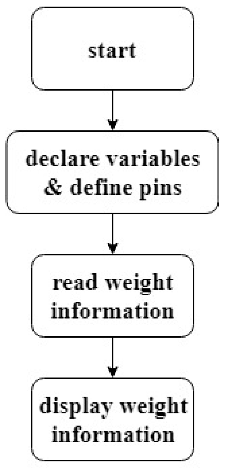
The master controller receives medicine numbers and the required weight information and converts the medicine number to the gallipot position based on a look-up table. The master controller then sends out the position orders to the operation controllers (automatic weighing controllers). This process is shown in Figure 17.
2.2.2. Automatic Weighing Controller
Figure 18 displays a block diagram of the functions of the automatic weighing controller. Arduino MEGA is selected as the controller, because it has more GPIO pins to connect with other controllers and sensors than Arduino UNO and Raspberry Pi. Arduino MEGA also has a larger current output capacity for driving the stepping motors.
Figure 19 shows a schematic diagram of the automatic weighing controller controlling four motors. After receiving the orders from the master controller, the automatic weighing controller outputs pulse signals to the guide motor in order to move the automatic weighing mechanism to the assigned gallipot position and then give orders to the retraction motor on the retractable platform for the extension operation of the platform. For linear guide movement, limit switches are used for positioning. When the automatic weighing mechanism approaches the assigned position and comes into contact with the limit switch, the controller stops running the guide motor. Similarly, the retractable mechanism is also equipped with limit switches for detecting the extension or retraction state of the retractable platform. Furthermore, the rotation motor controls the powder discharge, and therefore the powder weight, and the medicine spoon motor controls the flipping of the spoon for pouring the powder. Small stepping motors are used for the rotation motor, the medicine spoon motor, and the retractable motor, while a stepping motor with greater power is utilized as the guide motor.
Guide Positioning Control
For the discharge and weighing of powder, the linear guide is controlled to slide the weighing mechanism to the assigned gallipot. The block needs to be accurately guided to the assigned position so that the powder discharge coupler on the weighing mechanism is able to accurately couple with the drive of the gear discharge mechanism on the gallipot base. Nevertheless, the block bears the weights of all components on the weighing mechanism, potentially resulting in inadequate starting torque when the guide motor directly starts at the requested speed. This situation could cause starting failure due to stalling or blocking. After the guide motor starts running, if control pulse signals are abruptly stopped when the block reaches the stop point, the motor rotor would pass the equilibrium point due to the system inertia. When the inertia is great, the stepping motor rotor might turn to the next equilibrium point, causing inaccurate positioning. Therefore, stalling and overshooting will appear, respectively, during the starting and stopping periods, and proper speed control for the stepping motor would need to be applied for starting and stopping.
Motors play a critical role in automation. Motors can be categorized into direct-current motors, alternate-current motors, servomotors, and stepping motors, based on their structure and control methods. From the perspective of horsepower, DC motors and AC motors present better horsepower; however, servomotors and stepping motors present better position control.
A stepping motor (stepper motor; step motor), as a type of DC brushless motor, possesses matched stator gear teeth (toothed electromagnets) and rotor gear teeth. The operating principle of a stepping motor is to energize one electromagnet by an external drive circuit to attract the rotor gear teeth. When the gear’s teeth are aligned to the first electromagnet, they are slightly offset from the next electromagnet. Then the next electromagnet is energized, and the first is de-energized, making the gear rotate slightly to align with the next one. This process is repeated, and each of these rotations is called a step, moving the shaft by a fixed angle. A stepping motor is controlled by open-loop control, which is simple and does not need any positioning sensors, such as Hall sensors or encoders, so that the cost on control is low. The input signals are pulse signals, and a stepping motor rotates proportionally with the pulse signals in order to achieve accurate control of position and speed with good stability.
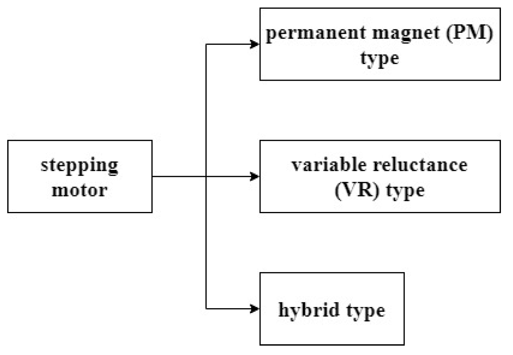
According to their structure, stepping motors can be classified into the permanent magnet (PM) type, the variable reluctance (VR) type, and the hybrid type, as shown in Figure 20.
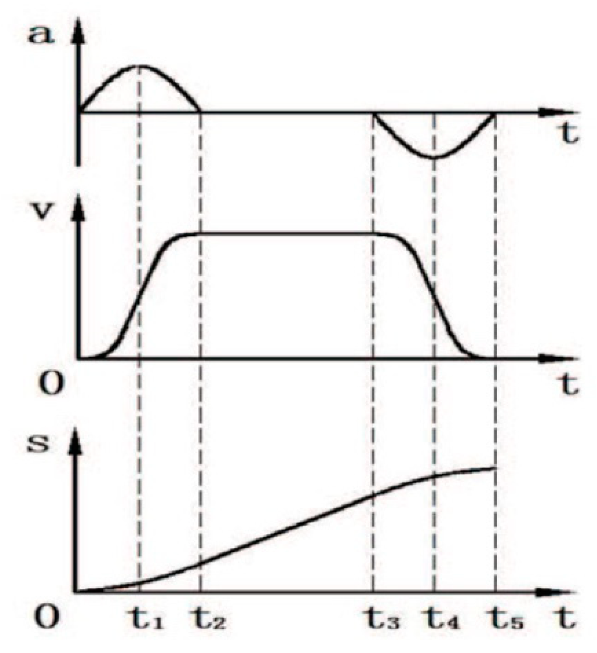
Figure 21 displays the schematic diagram of the stepping motor control, where a microcontroller sends out a train of pulses and a driver amplifies the signals to move the shaft through a fixed angle. Because open-loop control is used for stepping motors, preventing the stepping motor from stalling and overshooting becomes key to their operation. Therefore, the starting and stopping speedsof a stepping motor should be controlled properly. Two different speed control methods are used in this study. The first speed control method is trapezoidal curve control. Figure 22 shows a constant speed operation during the period t2, a constant acceleration during the starting period t1, and a constant deceleration during the stopping period t3. Based on the definition of “stalling”, when the changes of the control frequency for acceleration during t1 or deceleration during t3 are larger than what a stepping motor can respond to, stalling will stop the stepping motor. This would affect the normal operation of the system. For this reason, the speed changes of a stepping motor must be accurately controlled. The trapezoidal curve control uses constant acceleration and deceleration. The second method is the S-curve speed control, as shown in Figure 23. The speed change at the beginning of acceleration/deceleration is slower and increases gradually. The speed change slows down again when approaching the end of acceleration/deceleration. Several possible S-curves have been proposed, including the sine curve, quadratic curve, cyclic curve, and cubic curve. In this study, a parabolic curve, as described in [16], is used. Equations (6)–(8) are the functions for acceleration, velocity, and moving distance. The values of α and β are constrained by β = αt2. Since the stepping motor is driven by the pulses from the microcontroller, the desired number of pulses in each discrete time is determined on the basis of Equation (10), where θe is the step angle of the stepping motor, and r is the axle radius of the stepping motor.
Two methods are used for controlling the motor positioning. First, the distance between two adjacent gallipots is measured, the number of pulses (steps) required for the stepping motor to move this distance is calculated, and the necessary steps from the starting point to the destination are then utilized for speed control using either trapezoidal or S-curve control to prevent stalling and overshoot. Second, limit switches are used in order to detect the correct positions. These two methods could support each other. Both counting steps and receiving the signal from the limit switch can be used to determine whether the block reaches the destination or not. If both determinations are successful, accurate positioning has been achieved. If the signal from the limit switch stop the motor is received first to, the steps counted by the software are less than the pre-set steps, and overshoot occurs, although the positioning is still accurate. If the steps counted by the software reach the pre-set steps first but the limit switch has not been activated, stalling occurs, the positioning by the software is not accurate, and troubleshooting is needed. Figure 24 displays the flow chart of the speed and positioning control for the guide motor.
Weighing Control
The weighing module equipped with a controller is shown in Figure 25. The deformation of the load arm caused by the measured object on the weighing module changes the resistance of the strain gauge and results in a voltage signal which is then amplified through the HX711ADC conversion module. The readout converted by the software is the weight of the object. The weighing element is able to read up to 1 kg, with a resolution of 0.01 g. The application of this weighing module to the dispensing of scientific Chinese medication powder could be used to accurately measure powder weight to avoid excess powder waste, decrease the manpower required for weighing and packing traditional Chinese medicine, accelerate the dispensing process in pharmacies, and establish systematic dispensing and weighing process records, thus promoting precise medical treatment. Figure 26 displays the operation process of a weighing module, and Figure 27 shows the weighing control process. The controller reads the data transmitted from the weighing module and compares this with the set value in order to judge whether the set weight has been achieved; if not, the rotation motor continues operation until the weight appears within the target weight range. This automatic weighing aims to reduce the workload of pharmacists for scientific Chinese medication dispensing.
Weighing Mechanism Retraction Control
The weighing mechanism on the linear guide is a translation mechanism. For convenient operation, the weighing mechanism is detached from the gallipot base on the medicine shelf. Successive automatic powder discharge and weighing procedures could be followed by extending the powder discharge coupler on the retractable platform of the weighing mechanism to couple the drive of the discharge mechanism to the gallipot base. This process is shown in Figure 28. The retractable platform of the weighing mechanism is able to judge the platform extension/retraction displacement on the basis of the equipped limit switches. The stepping motor drives the lead screw for the extension/retraction of the platform. When the platform touches the limit switch, a high potential is generated, such that the controller will stop the operation of the stepping motor.
2.2.3. Lifting Controller
The automatic powder dispensing machine possesses a multi-shelf medicine chest, with each shelf having an independently operating controller to independently complete automatic dispensing and weighing. The weighed powder has to be collected in a mixing bowl. The lifting platform mechanism that places the mixing bowl was also designed to collect the weighed traditional Chinese medicine from different shelves. Arduino MEGA was selected as the controller for the lifting platform. It mainly controls the stepping motor operation so that the weighing mechanism can pour the weighed powder into the mixing bowl when the platform reaches its assigned position (height). The control operation process is shown in Figure 29. The controller determines to which shelf the platform should be raised/lowered, on the basis of the completion of the weighing procedure at different shelves. The stepping motor drives the raising and lowering, and the limit switch determines the position at which the motor is stopped.
3. Results
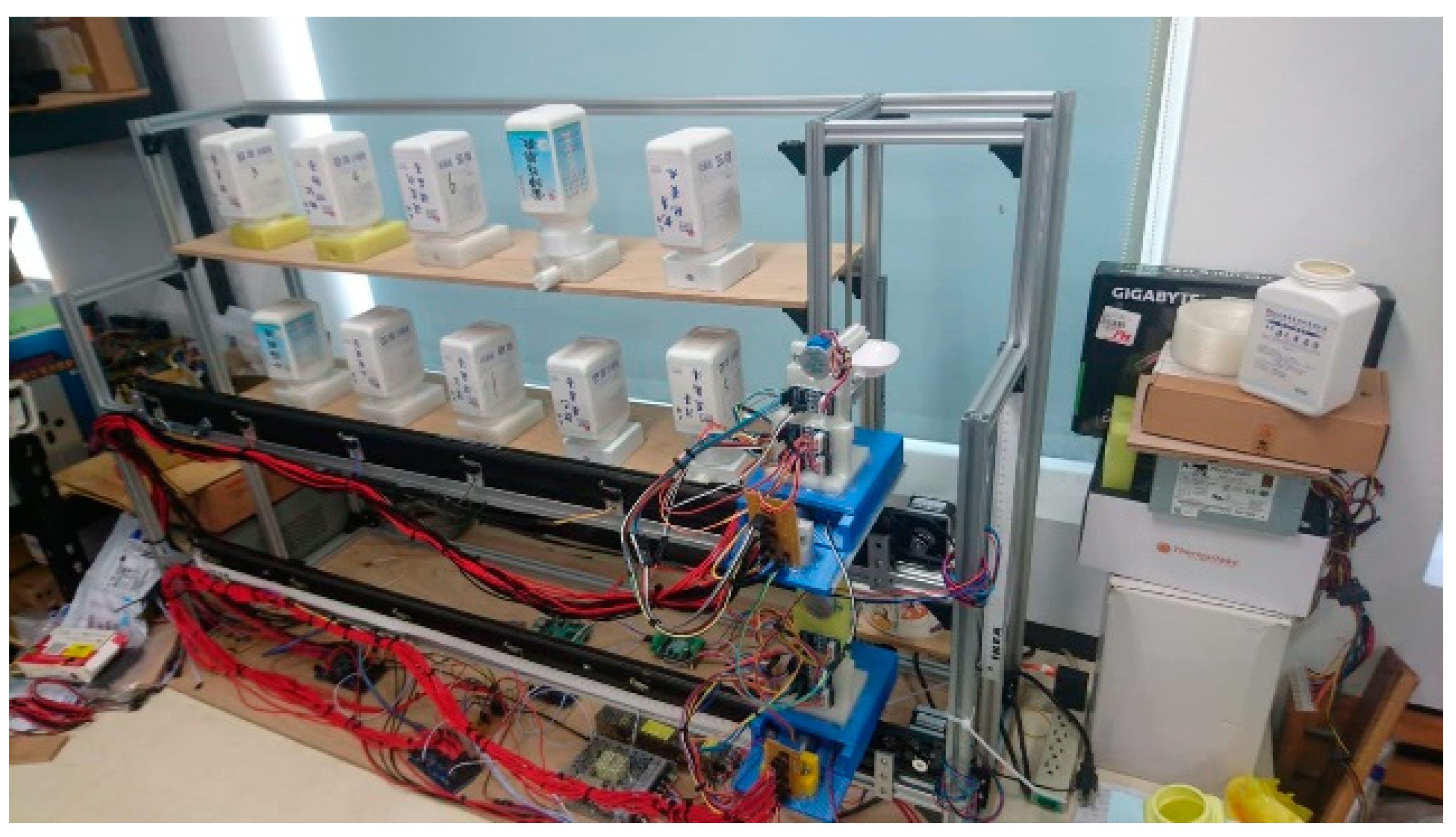
Figure 30 displays the appearance of the automatic powder dispensing machine using a shelf-based mechanism, with an aluminum extrusion assembly as the frame material, and components of weighing mechanism and gallipot base being 3D printed. Figure 31 shows the flowchart of the system operation. First, the controller receives the prescription information and moves the guide block to the assigned gallipot. Based on the required dose weight, the weighing mechanism drives the screw through the stepping motor to extend the retractable platform, where the powder discharge coupler is coupled with the drive of the discharge mechanism on the gallipot base. The rotation motor drives the discharge mechanism to drop the powder into the medicine spoon until the designated weight is reached. The retractable platform on the weighing mechanism is then retracted, and the block returns to its initial position. The lifting platform is further operated in order to raise/lowered it to the position of the medicine spoon following the completion of weighing. When the lifting platform is in position, the retractable platform on the weighing mechanism is extended to flip the medicine spoon and pour the powder. The lifting mechanism then proceeds to the next operation, having completed the above operation, and determines the entry of the next prescription. If there is no next prescription, then dispensing is completed.
To test the system effectiveness, we carried out a weighing precision test, transverse displacement positioning precision test, lifting platform stability test, transverse displacement speed test, and discharge speed test.
3.1. Weighing Precision Test
When dispensing traditional Chinese medicine, pharmacists weigh the medicine according to the prescription. The proposed system automatically dispenses powder, and the amount of powder discharged is accurately controlled. The weighing precision test is carried out under distinct automatic discharge weights, including 3 g, 5 g, 10 g, 15 g, 18 g, and 21 g, 3 times each, in order to calculate the average absolute error and the maximal error and thus to verify the weight accuracy within a reasonable range.
With thrice repeated weighing for each different weight, we subsequently obtain three measurement (absolute) errors for each different weight. The maximal error is selected, and the mean error is calculated (sum of 3 absolute errors divided by 3) for each weight, e.g., the maximal error among 3 measurements for the weight of 10 g was 0.06 g, and the absolute mean error of these 3 measurements was 0.03 g. The red line in Figure 32 shows the maximal errors for the different weights, and the blue line shows the absolute mean error. The absolute mean error (blue line) appeared in the range of 0.03 g~0.28 g. Then, the average absolute error (sum of all six absolute mean errors divided by 6) was 0.17 g, thus achieving the expected goal of the design.
3.2. Transverse Displacement Positioning Precision Test
The powder discharge coupler on the weighing mechanism must be accurately coupled with the drive of the discharge mechanism on the based of each gallipot on the medicine shelf in order to rotate the gear push element to discharge the powder from the gallipot for weighing. The coupling parts are shaped like teeth. Under 2 mm positioning error, the weighing mechanism normally drives the rotation of the discharge mechanism. It is necessary to test whether the weighing mechanism on the block driven by the linear guide accurately moves to the assigned position.
When designing the hardware mechanism, the positioning point of each gallipot position is set. A tape ruler is attached to the side of the linear guide in order to observe the distance moved. The zero point on the ruler is close to point F. The weighing mechanism, driven by the guide motor, moves from A (initial position) to the positions (B, C, D, E, and F) of the assigned gallipots and then back to A. The position of at which it stops is recorded. The experiment was repeated five times for each point, and the test results are shown in Figure 33, whereby the linear guide motor does not exhibit stalling or overshoot during operation. When the guide motor moves the weighing mechanism to point F, it should stop at 3.0 cm (expected position). However, it stops at 3.1 cm (green line), and the errors are all 0.1 cm for 5 tests. For points E and C, the errors are all 0.0 cm for 5 tests. For points A and B, the errors are all 0.1 cm for 5 tests. For point D, the errors are all 0.2 cm for 5 tests. Therefore, the error is within 2 mm, conforming to the design requirement.
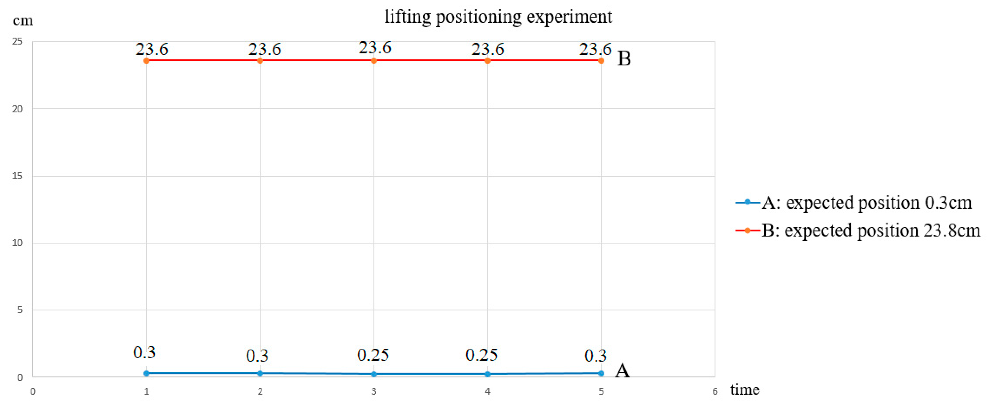
3.3. Lifting Platform Stability Test
A mixing bowl is placed on the lifting platform to collect the weighed powder from each shelf to test the stability of the lifting positioning. The platform has to be in the position below the medicine spoon with enough room so that the medicine spoon can be flipped to pour powder without leaking or spreading the powder. A tape ruler is attached on the side of the lifting mechanism in order to observe the stopping position. for the experiement was repeated five times and the position data recorded; the results are shown in Figure 34. For point A, the errors are all 0.0 cm for 5 tests. For point B, the errors are all 0.2 cm for 5 tests. The error exhibited is within 2 mm, which is an acceptable engineering accuracy range.
3.4. Transverse Displacement Speed Test
The horizontal movement speed of the weighing mechanism is related to the dispensing time. Two different speed control curves, the trapezoidal curve and the S-curve, are utilized for testing the average speed by moving the block from the initial position to different positions. The pulse frequency used during the constant speed interval for these two speed control methods is 3.125 kHz.
Table 2 lists the times measured from the initial point to various positioning points using trapezoidal speed control. The transverse movement speed is subsequently calculated, as shown in Table 3. Table 4 lists the time measured from the starting point to various positioning points using the S-curve speed control. The transverse moving speed is also calculated, as shown in Table 5. The data show that the average transverse moving speed for the S-curve is 23.89 cm/s, which is faster than that of the trapezoidal curve, which is 21.79 cm/s. Additionally, S-curve speed control is more stable during acceleration and deceleration periods than the trapezoidal speed control.
3.5. Discharge Speed Test
The effectiveness of this system should balance the powder weight precision and discharge speed. By measuring the time required for automatic discharge using different discharge weights, the discharge speed is calculated. Table 6 lists the time for discharging different weights, and Table 7 shows the corresponding average discharge speed. The average discharge speed of the automatic weighing mechanism is 0.22 g/s.
4. Discussion
In the presented design, each Chinese medicine powder gallipot is equipped with its own base with a powder discharge mechanism. 3D printing was used for the prototype of the gallipot base, demonstrating the feasibility of this design. For future commercialization, the gallipot base can be mass produced, and the cost per unit will be low due to its simple design.
Since each gallipot has its own base, cross-contamination of the powder will not occur while discharging. Moreover, the power driving the discharge mechanism comes from the stepping motor on the weighing mechanism via the coupling of the coupler and the drive. Although many gallipot bases are required for each shelf, only one weighing mechanism is needed for each shelf. The stepping motors used on the weighing mechanism for rotating the coupler, flipping the medicine spoon, and retracting/extending the retractable platform are 200 steps per revolution at 100 Hz. The average speed of powder discharge is 0.22 g/s. Faster stepping motors could be used to improve the discharge speed for commercialization of this machine.
The number of shelves can be increased in accordance with the needs of the application, as an aluminum extrusion frame is utilized. The presented machine has two shelves, with a total of 10 gallipots. If 100 gallipots were needed, a 5-shelf machine could be designed with 20 gallipots on each shelf. The size of such a design would have a height of 160 cm and a width of 200 cm. The estimated cost for this 5-shelf 100-gallipot machine would be $1800.
Since powder discharge is achieved by the coupling of the coupler teeth and the drive teeth, it is necessary to precisely move the weighing mechanism to the gallipot base at the right position so that the rotation motor is able to drive the discharge mechanism. Furthermore, it is also necessary to raise/lower the mixing bowl on the lifting platform to the right position in order to collect the powder from the medicine spoons. Positioning errors for both were all within 2 mm, satisfying the precision requirement.
The weighing element used in this study can read up to 1 kg, at the resolution 0.01 g. The weighing average absolute errors were in the range of 0.03 g~0.28 g. For a 3-day, 9-dose prescription (3 doses per day), the weighing errors per dose were in the range of 0.003 g~0.03 g, which is acceptable.
Since the weighing mechanism consists of three motors, a load cell, and other parts, its weight is not light. Moreover, its moving speed affects the dispensing time. A more powerful stepping motor is used for driving this weighing mechanism. Two different speed control curves, trapezoidal curve and S-curve, were tested. The average transverse moving speed of the S-curve was faster than that of the trapezoidal curve. The S-curve speed control was also more stable during starting and stopping periods than the trapezoidal speed control.
With the help of the weighing mechanism, the powder consumption of each gallipot can now be systematically recorded in the database. Therefore, the development of a gallipot inventory becomes possible. In the future, a management system could be developed to send an alarm when a gallipot is almost depleted for replacement. Another interesting feature that would also be feasible is optimal gallipot location planning for faster dispensing. Based on historical statistical data, it would be possible to place the most commonly used Chinese medicine at locations as close as possible to the initial position of the weighing mechanism, resulting in faster dispensing.
Since the gallipot bases were printed by a 3D printer, the quality of the gallipot bases leaves room for improvement in the commercialization of this machine. Nano coating can also be applied to gallipot bases and medicine spoons, so that powder particles do not adhere to the bases and spoons. This will also increase the accuracy of powder discharge and prevent powder cross-contamination on the spoon.
5. Conclusions
A shelf-based automatic powder dispensing machine was presented in this study to improve the workload of Chinese medicine pharmacists, who currently dispense and weigh powder manually. The system is framed with aluminum extrusion bars, on which linear guide mechanisms and 3D-printed components are assembled. Software and hardware were designed to control the motor positioning/speed of the control systems and for automatic weighing. Mechatronics were applied to implement the functions of automatic dispensing, automatic weighing according to the prescription, and automatic pouring of the dispensed powder into the mixing bowl.
In the entire operation process of the system, the target functions operated normally. Driving the weighing mechanism to the assigned position and extending the retractable platform in order to couple the discharge mechanism with the gallipot base were correctly controlled. Also, the gear push element was able to accurately drop the powder into the medicine spoon for automatic weighing.
After testing, the system showed an average absolute error of weighing of 0.17 g, a horizontal positioning accuracy within 2 mm, a lifting platform positioning accuracy also within 2 mm, a transverse moving average speed of 23.89 cm/s with the S-curve speed control, and an average powder discharge speed of 0.22 g/s.
The system is indeed able to provide the functions needed for the automatic dispensing and weighing of traditional Chinese medicine, offering systematic traditional Chinese medicine dispensing history records, and promoting traditional Chinese medicine dispensing efficiency and accuracy.
6. Patents
The work presented in this paper has been filed for a patent (pending) in Taiwan.
Author Contributions
Conceptualization, J.-Y.L., C.-C.H. and Y.-C.W.; methodology, J.-Y.L., J.-M.L., C.-C.H. and Y.-C.W.; software, J.-M.L. and C.-S.C.; validation, J.-Y.L., J.-M.L., C.-C.H. and Y.-C.W.; formal analysis, J.-Y.L. and J.-M.L.; investigation, J.-Y.L. and J.-M.L.; resources, J.-Y.L.; data curation, J.-M.L. and Y.-C.W.; writing—original draft preparation, J.-M.L. and Y.-C.W.; writing—review and editing, Y.-C.W.; visualization, J.-M.L.; supervision, J.-Y.L., C.-C.H. and Y.-C.W.; project administration, C.-C.H. and C.-S.C.; funding acquisition, J.-Y.L., C.-C.H. and Y.-C.W.
Funding
This research was funded by the Ministry of Science and Technology, Taiwan, grant numbers MOST 108-2221-E-239-024 and MOST 108-2221-E-239-025.
Conflicts of Interest
The authors declare no conflict of interest. The funders had no role in the design of the study; in the collection, analyses, or interpretation of data; in the writing of the manuscript, or in the decision to publish the results.
References
- Chinese Medicine Pharmacists Shortage. Available online: https://www.youtube.com/watch? v=2dfPVPG9p28 (accessed on 9 October 2019).
- Lee, Y.J.; Chen, S.C. Traditional Chinese Medicine Electric Barcode Check and Medicine Chest Light Display System; The Journal of Taiwan Pharmacy: Taipei, Taiwan, 2014; Volume 30. (In Chinese) [Google Scholar]
- Tu, G.H. Using RFID Technology on Chinese Medicine Clinic’s Pharmacy Operation Management and Development of Intelligent Medicine Dispensing Cabinet. Master’s Thesis, Tungnan University of Science and Technology, Taiwan, China, 2009. (In Chinese). [Google Scholar]
- Nong’s Traditional Chinese Medicine Formulation. Available online: https://www.youtube.com/watch? v=gq8F1Vy_VCk (accessed on 9 October 2019).
- Tian Jiang Herbs Intelligent Distribution System. Available online: https://www.youtube.com/watch? v=C0gm8mFr-p4 (accessed on 9 October 2019).
- Yuyama, S.; Asaoka, C.; Iwatani, T.; Kasuya, M.; Yoshina, K. Dispensing Device. Taiwan Patent Application No. 201605689 (pending), 16 February 2016. (In Chinese). [Google Scholar]
- Intelligent Traditional Chinese Medicine Dispensing Structure. Available online: https://twpat-simple.tipo.gov.tw/tipotwoc/tipotwkm?!!FR_M445551 (accessed on 9 October 2019).
- Lu, P. Vending Machine with Automated Detection of Product Position. U.S. Patent No. 8,706,293 B2, 22 April 2014. [Google Scholar]
- Derammelaere, S.; Verbelen, F.; Stockman, K. Open Loop Control of a Stepping Motor with Step Loss Detection and Stall Detection using Back-EMF Based Load Angle Estimation. In Proceedings of the 2014 IEEE/ASME International Conference on Advanced Intelligent Mechatronics (AIM), Besançon, France, 8–11 July 2014. [Google Scholar]
- Dorin-Mirel, S.; Ion, M. The Analysis of Different Frequency for a Stepper Motor Open Loop Operation. In Proceedings of the International Conference on Electronics, Computers and Artificial Intelligence, Pitesti, Romania, 2–30 July 2016. [Google Scholar]
- Melin, P.; Castillo, O. Adaptive Control of a Stepping Motor Drive using a Hybrid Neuro-fuzzy Approach. In Proceedings of the 10th IEEE International Conference on Fuzzy Systems, Melbourne, Australia, 2–5 December 2001. [Google Scholar]
- Jang, J.S.R.; Sun, C.T.; Mizutani, E. Neuro-Fuzzy and Soft Computing; Prentice-Hall: New Jersey, NJ, USA, 1997. [Google Scholar]
- Betin, F.; Pinchon, D.; Capolino, G.-A. Fuzzy Logic Applied to Speed Control of a Stepping Motor Drive. IEEE Trans. Ind. Electron. 2000, 47, 610–622. [Google Scholar] [CrossRef]
- Gong, S.; He, B. LabView-based Automatic Rising and Falling Speed Control of Stepper Motor. In Proceedings of the International Conference on Electrical Machines and Systems, Tower Hall Funabori, Tokyo, Japan, 15–18 November 2009. [Google Scholar]
- Mihalache, G.; Zbant, A.; Livint, G. Open-loop Control of Hybrid Stepper Motor with Two Phases using Voltage to Frequency Converter. In Proceedings of the International Symposium on Advanced Topics in Electrical Engineering, Bucharest, Romania, 23–25 May 2013. [Google Scholar]
- Zhang, L.; Liu, L.; Shen, J.; Lai, J.; Wu, K.; Zhang, Z.; Liu, J. Research on Stepper Motor Motion Control Based on MCU. In Proceedings of the 2017 Chinese Automation Congress, Jinan, China, 20–22 October 2017; pp. 3122–3125. [Google Scholar]
- Shi, J.; Shi, J. Open-loop Stepping Drive of Permanent Magnet Synchronous Motor. In Proceedings of the IEEE International Conference on Industrial Technology, Chengdu, China, 21–24 April 2008. [Google Scholar]
- Ali, Z.; Kshirsagar, R.V. Development of CPLD Based Novel Open Loop Stepper Motor Controller for High Performance using VHDL. In Proceedings of the IEEE 14th International Conference on Intelligent Engineering Systems, Las Palmas, Spain, 5–7 May 2010; pp. 307–312. [Google Scholar]
- Yang, S.M.; Su, P.D. Active Damping Control of Hybrid Stepping Motor. In Proceedings of the 4th International Conference on Power Electronics and Drive Systems, Denpasar, Indonesia, 25–25 October 2001; pp. 749–754. [Google Scholar]
- Bodson, M.; Sato, J.S.; Silver, S.R. Spontaneous Speed Reversals in Stepper Motors. In Proceedings of the 42nd IEEE International Conference on Decision and Control, Maui, HI, USA, 9–12 December 2003; Volume 4, pp. 3319–3324. [Google Scholar]
- Ohtsuka, A.; Koyama, T.; Kohashi, T.; Adachi, M. Digital Creep Compensation Method for Load Cell in Various Loading Patterns. In Proceedings of the ICROS-SICE International Joint Conference, Keisoku Jidō Seigyo Gakkai, Japan, 18–21 August 2009. [Google Scholar]
- Li, L.; Yang, Z. The application of Double Load Cells Self-Balance Method on the Static Load Test of Long Post-Grouting Pile with Great Diameter. In Proceedings of the 7th International Conference on Intelligent Computation Technology and Automation, Changsha, China, 25–26 October 2014. [Google Scholar]
- Richiedei, D.; Trevisani, A. Shaper-Based Filters for the Compensation of the Load Cell Response in Dynamic Mass Measurement. Mech. Syst. Signal Process. 2018, 98, 281–291. [Google Scholar] [CrossRef]
- Chang, Y.S.; Lin, T.C. An Optimal G-shaped Load Cell for Two Range Loading. Eng. Agric. Environ. Food 2013, 6, 172–176. [Google Scholar] [CrossRef]
- Piskorowski, J.; Barcinski, T. Dynamic Compensation of Load Cell Response: A Time-varying Approach. Mech. Syst. Signal Process. 2008, 22, 1694–1704. [Google Scholar] [CrossRef]
- Lin, H. Nonlinear Error Compensation for Load Cells Based on the Optimal Neural Network with an Augmented Lagrange Multiplier. IEEE Trans. Instrum. Meas. 2015, 64, 2850–2862. [Google Scholar] [CrossRef]
- Li, R.; Ryan, J.K. A Bayesian Inventory Model Using Real-time Condition Monitoring Information. Prod. Oper. Manag. 2011, 20, 754–771. [Google Scholar] [CrossRef]
- Cao, L.; Goggans, P. Terminal Location Planning in Intermodal Transportation with Bayesian Inference Method; Project Report; The University of Mississippi: Mississippi, MS, USA, 2014. [Google Scholar]
- Imani, M.; Choreishi, S.F.; Allaire, D.; Braga-Neto, U. MFBO-SSM: Multi-Fidelity Bayesian Optimization for Fast Inference in State-space Models. In Proceedings of the AAAI Conference on Artificial Intelligence, Hawaii, HI, USA, 27 January–1 February 2019; Volume 33, pp. 7858–7865. [Google Scholar]
- Imani, M.; Ghoreishi, S.F.; Braga-Neto, U. Bayesian Control of Large MDPs with Unknown Dynamics in Data-poor Environments. In Advances in Neural Information Processing Systems 31; Bengio, S., Wallach, H., Larochelle, H., Eds.; Neural Information Processing Systems Foundation, Inc.: San Diego, CA, USA, 2018; pp. 8146–8156. [Google Scholar]
- Huang, H.L.; Tseng, T.L. Weighing Machine. Master’s Thesis, Department of Electrical Engineering, Hsiuping University of Science and Technology, Taiwan, 2010. [Google Scholar]
Figure 1.
Block diagram of mechanisms.

Figure 2.
Schematic diagram of mechanism.

Figure 3.
Direct-drive linear motor.

Figure 4.
Guide positioning points.

Figure 5.
Gallipot base mechanism.

Figure 6.
Gallipot base.

Figure 7.
Gear discharge mechanism: (a) Gear push element–discharge mechanism; (b) Schematic diagram of discharge mechanism.
Figure 7.
Gear discharge mechanism: (a) Gear push element–discharge mechanism; (b) Schematic diagram of discharge mechanism.

Figure 8.
Weighing mechanism: (a) during linear guide movement; (b) during weighing process.

Figure 9.
Architecture diagram of load cell scale.

Figure 10.
Relationship between conductor length and resistance.

Figure 11.
Schematic diagram of automatic powder weighing hardware architecture.

Figure 12.
Weighing mechanism entity.

Figure 13.
Lifting mechanism.

Figure 14.
Architecture diagram of the control system operation process.

Figure 15.
Architecture diagram among controllers.

Figure 16.
Block diagram of master controller function.

Figure 17.
System flowchart of master controller.

Figure 18.
Block diagram of automatic weighing controller functions.

Figure 19.
Schematic diagram of automatic weighing controller controlling four motors.

Figure 20.
Classification of stepping motors.

Figure 21.
Schematic diagram of stepping motor control.

Figure 22.
Trapezoidal-curve speed control [16].
Figure 22.
Trapezoidal-curve speed control [16].

Figure 23.
S-curve speed control [16].
Figure 23.
S-curve speed control [16].

Figure 24.
Flowchart of speed and positioning control for guide motor.

Figure 25.
Weighing module.

Figure 26.
Weighing module operation process.

Figure 27.
Weighing control process.

Figure 28.
Weighing control process.

Figure 29.
Lifting control process.

Figure 30.
Appearance of automatic powder dispensing machine.

Figure 31.
Flowchart of system operation.

Figure 32.
Weighing errors.

Figure 33.
Transverse displacement experimental data.

Figure 34.
Transverse displacement experimental data.


Table 1.
Advantages and disadvantages of load cell.
| Advantages | Disadvantages |
|---|---|
|
|
Table 2.
Transverse moving time with trapezoidal-curve speed control.
| Unit: s | ||||||
|---|---|---|---|---|---|---|
| Times | 1 | 2 | 3 | 4 | 5 | Average Time |
| Point B | 1.1 | 1.1 | 1.1 | 1.1 | 1.1 | 1.1 |
| Point C | 1.8 | 1.7 | 1.8 | 1.8 | 1.8 | 1.8 |
| Point D | 2.4 | 2.4 | 2.3 | 2.4 | 2.4 | 2.4 |
| Point E | 3.0 | 3.1 | 3.0 | 3.0 | 3.0 | 3.0 |
| Point F | 3.6 | 3.5 | 3.6 | 3.5 | 3.6 | 3.6 |
Table 3.
Transverse moving time with trapezoidal-curve speed control.
| Unit: cm/s | |||||
|---|---|---|---|---|---|
| Point B | Point C | Point D | Point E | Point F | |
| speed | 17.46 | 20.20 | 22.81 | 23.84 | 24.84 |
| average speed | 21.79 | ||||
Table 4.
Transverse moving time with S-curve speed control.
| Unit: s | ||||||
|---|---|---|---|---|---|---|
| Times | 1 | 2 | 3 | 4 | 5 | Average Time |
| Point B | 1.3 | 1.3 | 1.3 | 1.3 | 1.3 | 1.3 |
| Point C | 2.0 | 2.0 | 2.0 | 2.0 | 2.0 | 2.0 |
| Point D | 2.6 | 2.6 | 2.6 | 2.6 | 2.6 | 2.6 |
| Point E | 3.2 | 3.2 | 3.2 | 3.2 | 3.2 | 3.2 |
| Point F | 3.8 | 3.8 | 3.8 | 3.8 | 3.8 | 3.8 |
Table 5.
Transverse moving time with S-curve speed control.
| Unit: cm/s | |||||
|---|---|---|---|---|---|
| Point B | Point C | Point D | Point E | Point F | |
| speed | 20.64 | 22.44 | 24.71 | 25.43 | 26.22 |
| average speed | 23.89 | ||||
Table 6.
Discharge time.
| Unit: s | ||||
|---|---|---|---|---|
| 3 g | 5 g | 10 g | 15 g | |
| 1 | 11.3 | 22.4 | 46.0 | 80.0 |
| 2 | 11.1 | 23.5 | 44.5 | 78.5 |
| 3 | 11.4 | 22.0 | 43.7 | 83.0 |
| average time | 11.27 | 22.63 | 44.73 | 80.50 |
Table 7.
Discharge speed.
| Unit: g/s | ||||
|---|---|---|---|---|
| 3 g | 5 g | 10 g | 15 g | |
| speed | 0.27 | 0.22 | 0.22 | 0.19 |
| average speed | 0.22 | |||
© 2019 by the authors. Licensee MDPI, Basel, Switzerland. This article is an open access article distributed under the terms and conditions of the Creative Commons Attribution (CC BY) license (http://creativecommons.org/licenses/by/4.0/).
Share and Cite
MDPI and ACS Style
Lin, J.-Y.; Lin, J.-M.; Han, C.-C.; Wu, Y.-C.; Chang, C.-S. An Automatic Chinese Medicine Dispensing Machine Using Shelf-Based Mechanism. Appl. Sci. 2019, 9, 5060. https://doi.org/10.3390/app9235060
AMA Style
Lin J-Y, Lin J-M, Han C-C, Wu Y-C, Chang C-S. An Automatic Chinese Medicine Dispensing Machine Using Shelf-Based Mechanism. Applied Sciences. 2019; 9(23):5060. https://doi.org/10.3390/app9235060
Chicago/Turabian StyleLin, Jin-Yuan, Jing-Min Lin, Chin-Chuan Han, Yu-Chi Wu, and Chao-Shu Chang. 2019. "An Automatic Chinese Medicine Dispensing Machine Using Shelf-Based Mechanism" Applied Sciences 9, no. 23: 5060. https://doi.org/10.3390/app9235060
Note that from the first issue of 2016, this journal uses article numbers instead of page numbers. See further details here.