Multi-Perspective Ultrasound Imaging Technology of the Breast with Cylindrical Motion of Linear Arrays
by
 ,
,
Chang Liu
1,2, 
Binzhen Zhang
1,*,
Chenyang Xue
1,*,
Wendong Zhang
1,
Guojun Zhang
1 and
Yijun Cheng
3 1
Key Laboratory of Instrumentation Science & Dynamic Measurement, North University of China, Ministry of Education, Taiyuan 030051, China
2
School of Electrical and Electronic Engineering, Dalian Vocational Technical College, Dalian 116037, China
3
Department of Electronic and Engineering, Taiyuan Institute of Technology, Taiyuan 030008, China
*
Authors to whom correspondence should be addressed.
Appl. Sci. 2019, 9(3), 419; https://doi.org/10.3390/app9030419
Submission received: 8 January 2019
/
Revised: 22 January 2019
/
Accepted: 23 January 2019
/
Published: 26 January 2019
(This article belongs to the Special Issue Ultrasound B-mode Imaging: Beamforming and Image Formation Techniques)
Abstract
:In this paper, we propose a multi-perspective ultrasound imaging technology with the cylindrical motion of four piezoelectric micromachined ultrasonic transducer (PMUT) rotatable linear arrays. The transducer is configured in a cross shape vertically on the circle with the length of the arrays parallel to the z axis, roughly perpendicular to the chest wall. The transducers surrounded the breast, which achieves non-invasive detection. The electric rotary table drives the PMUT to perform cylindrical scanning. A breast model with a 2 cm mass in the center and six 1-cm superficial masses were used for the experimental analysis. The detection was carried out in a water tank and the working temperature was constant at 32 °C. The breast volume data were acquired by rotating the probe 90° with a 2° interval, which were 256 × 180 A-scan lines. The optimized segmented dynamic focusing technology was used to improve the image quality and data reconstruction was performed. A total of 256 A-scan lines at a constant angle were recombined and 180 A-scan lines were recombined according to the nth element as a dataset, respectively. Combined with ultrasound imaging algorithms, multi-perspective ultrasound imaging was realized including vertical slices, horizontal slices and 3D imaging. The seven masses were detected and the absolute error of the size was approximately 1 mm where even the image of the injection pinhole could be seen. Furthermore, the breast boundary could be seen clearly from the chest wall to the nipple, so the location of the masses was easier to confirm. Therefore, the validity and feasibility of the data reconstruction method and imaging algorithm were verified. It will be beneficial for doctors to be able to comprehensively observe the pathological tissue.
1. Introduction
Breast cancer is one of the most harmful diseases to women in today’s society. Therefore, early detection and early treatment of breast cancer is particularly crucial [1]. The breast is made up of breast glands and other soft tissues without bones, which the cancerous tissues have higher density [2,3]. In order to avoid the harm of false positive to women, it is necessary to develop highly sensitive and specific diagnostic tools for early detection of breast cancer [4]. At present, the imaging technology for breast cancer mainly includes X-ray mammography, Magnetic resonance imaging (MRI) and ultrasound [5]. X-ray mammography has the advantages of high sensitivity and high specificity to calcification points [6]. Whereas, early lesion is small, similar to the density of surrounding glands and the boundary is not clear, hence the imaging effect in breast detection is not obvious [7]. Besides, because of the radiation hazards, early screening is not appropriate [8]. Although MRI has higher sensitivity, the specificity is rather poor [9]. In addition, its disadvantages are high costs and long inspection time, which is not conducive to early screening [10,11,12]. Likewise, breast ultrasound relies heavily on the doctor’s interpretation and is often used as a supplementary tool [13,14]. In general, biopsy is the gold standard for the diagnosis of breast cancer, which show that there are a lot of false-positive cases diagnosed by ultrasound imaging [15,16,17,18]. Ultrasound computer tomography (USCT) is a potential candidate for the imaging of breast cancer [19,20]. The simultaneous recording of reflection, speed of sound and attenuation images is the key superiority of the USCT system [21]. Comfort, safety and 3D imaging are the potential clinical benefits of ultrasound tomography [22,23].
Three-dimensional USCT, which is a new ultrasound imaging technology, promises high quality images with satisfactory reproducibility and could offer a better chance for survival by the detection of cancers at the early stage [24,25]. One problem that exists with the image reconstruction process is the assumption of 2D geometry while the object imaged is in 3D [26]. In a 2D image sequence, only clinicians with experience can estimate the size and shape of lesions and construct a three-dimensional geometric relationship between the lesion and its surrounding tissue [27]. This brings great difficulty to the accuracy and convenience of diagnosis and treatment and the specificity is poor [28]. Therefore, it is very necessary to visually demonstrate the collection data of USCT on a computer with different perspective [29]. Breast data were obtained from different perspectives and then ultrasound imaging analysis was conducted to observe tissue lesion information retrospectively, so as to improve specificity, further reduce misdiagnosis rate and avoid the pain caused by biopsy.
In this study, we addressed the multi-perspective imaging technology, which is used to diagnose breast lesions. A system with a cylindrical motion of four 1 × 128 PMUT linear arrays was applied to acquire the whole volume data using the optimized segmented dynamic focusing technology in the reflection mode. The data reconstruction was performed at a constant angle and according to the Nth element respectively. The experiment platform was set up and an ultrasound tomography algorithm was used to generate the vertical slice, horizontal slice and three-dimensional imaging. Furthermore, the characteristics of each perspective image were compared and analyzed.
2. Experiments and Methods
2.1. 3D Imaging System with Cylindrical Motion of Linear Arrays
We developed an original breast ultrasound imaging system with the cylindrical motion of four linear arrays. The setup was mainly used to diagnose breast lesions. Figure 1 shows the schematic diagram of the experimental setup and the connection of main components. Ultrasound imaging with the cylindrical motion of linear arrays is as shown in Figure 2. The transducer configuration scheme is shown in Figure 2a. The 1 × 128 PMUT was placed 90° cross vertically on the circle with the length of the arrays parallel to the axis of the circle, which was roughly parallel to the central axis of the breast. Figure 2b shows the dimensions (7 cm × 3 cm × 13.5 cm) of the linear array transducer and the active area (1.8 cm × 12.8 cm) of the transducer for imaging. The sensors were customized for the breast detection. The transducers surrounded the breast, which allowed for non-invasive detection. The detection was carried out in the water tank and the working temperature was constant at 32 °C. By controlling the electric rotary table controller through the PC workstation, the electric rotary table drives the PMUT to perform the cylindrical scanning. The cylindrical scanning diagram is shown in Figure 2c. The four PMUT linear arrays were arranged in a cross shape. The distance of the opposite PMUT was 180 mm and the array element center to center spacing was 1 mm. Hence, the maximum test aperture was 18 cm × 13 cm. Set 1 (Adjacent PMUT) and Set 2 (Another adjacent PMUT) operate alternately. A 64 channel ultrasonic transmitting/receiving acquisition circuit was employed to control the linear array. The data acquisition circuits had a sampling frequency of 40 MHz.
The breast volume data were obtained by performing the cylindrical scanning with a constant interval. For four linear array transducers, a full circle requires rotating the sensors 90 degrees. The step angle was set to 2°, therefore, it took 1.2 s for each rotation and 3 s for the vertical slice data collection. Hence, the whole scan time was about 3 minutes using a HP workstation (16G). The smaller the interval angle, the longer the scan time. Besides, the rotation precision was 0.05°, which allows for obtaining 7200 pulse echo signals. The optimized segmented dynamic focusing technology was used to improve the emission energy of the A-scan line, thereby improving the imaging quality. The high density was 256 scan lines and the low density was 128 scan lines, respectively; hence, the maximum data were 7200 × 256 A-scan lines. Multi-perspective ultrasound imaging of the breast could be obtained through the data reconstruction where the data could be reconstructed to obtain 7200 vertical slices, 256 horizontal slices and a three-dimensional imaging. By adopting four rotatable linear arrays to perform cylindrical scanning, it could make the sensor’s fabrication process easier and gain better consistency and reliability than a cylindrical array [30].
The 1 × 128 PMUT linear array was characterized using a precision impedance analyzer (Agilent E4990A) as shown in Figure 3. The ultrasound transducer had a static capacitance of 664 pF, an impedance of 64 Ω and the operating frequency of 3.5 MHz [30]. Eight elements were randomly selected to test the transmitting sensitivity Sv and receiving sensitivity M as shown in Figure 3a. The average value of Sv is -220.5875 dB and the average value of M is 166.775 dB. The consistency is ±[email protected]. The bandwidth experiment was conducted with the ultrasound transducer working as a transmitter and a standard transducer working as a receiver. The frequency response had a –6 dB bandwidth of 86.7% as seen in Figure 3b.
2.2. Multi-Perspective Ultrasound Imaging
This system was able to gain sufficient data and store it in the computer by rotating a full circle. These data could then be reconstructed to form multi-perspective breast ultrasound imaging as shown in Figure 4. Ultrasonic reflection imaging is mainly dependent on the acoustic impedance mismatch between different tissues [23]. In this paper, we describe the recombination method and ultrasound tomography algorithm from three perspectives, the details are as follows:
2.2.1. Vertical Slices
A total of 256 A-scan lines at a constant angle were recombined as a dataset; then, we used a Butterworth filter to process the data for decreasing signal noise. Envelope detection was carried out for the data after filtering and the contour of the signal was extracted. The enveloping signal was processed by logarithmic compression and the dynamic range of the image was adjustable. Then, a vertical slice could be produced using gray-scale imaging as shown in Figure 4a.
2.2.2. Horizontal Slices
A total of 7200 A-scan lines were recombined according to the nth element as a dataset. Then, a Butterworth filter was used to process the data for decreasing signal noise. Envelope detection was carried out for the data after filtering and the contour of the signal was extracted. The enveloping signal was processed by logarithmic compression and the dynamic range of the image was adjustable. The data were truncated to leave half the depth. The coordinate transformation of the data was carried out and the reference point is the center of the detection window. Then, a horizontal slice was acquired by using morphological processing including an inflation algorithm and a bicubic filling algorithm as shown in Figure 4b.
2.2.3. 3D Imaging
Reconstruction of the 3D breast imaging could be realized by merging the horizontal slices as shown in Figure 4c. The Medical Imaging ToolKit (developed by Institute of Automation of Academia Sinica) was used to realize the 3D visualization.
3. Principles
3.1. Focusing Delay Calculation
The focusing delay time is related to the parameters of the transducer and the position of the focal point. The main parameters involved in the ultrasound transducer include subarray number and array spacing. The subarray number of elements m was 64 and the array spacing d was 1 mm. The position of focal point P was on the central axis of the subarray and the depth of the scanning was 180 mm. The known parameters were the ultrasound velocity c and the sampling rate fs, which were 1520 m/s and 40 MHz, respectively. The calculation of the focusing delay time τ of the 64 channel linear array transducer is shown in Figure 5. However, the calculation only needed to consider channels 1 to 32, because the 64 channels were symmetrically related to the central axis of the subarray.
The focusing delay time τj(F, βj) of channel j can be calculated with the formula shown in Equation (1).
where the distance between array element j and the center axis is aj; the angle between the array element j and the center axis is βj; the focal length is F; the ultrasound velocity is c; the array spacing is d; and the minimum distance between the two adjacent focal points is ΔF [31,32,33].
3.2. Delay Data Analysis
The range of the scanning depth was 2 to 180 mm and the focusing delay data of 32 channels were calculated according to Equation (1). The delay focusing data of channels 1–32 update in real time with the change of the focal depth. The variation of focusing delay data relative to the focal depth F and channel j is shown in Figure 6. For the focal depth F and the channel j, the variation is a monotonically decreasing function. The smaller the distance between two adjacent focal points, the more focusing points means that the quality of the image is higher. Whereas, field programmable gate array (FPGA) consumption also increases. The tradeoff between image quality and FPGA consumption, the distance between two adjacent focal points, was 0.45 mm. These features showed that the following focusing delay data could be stored to some extent that used less memory.
The transmission and receiving of ultrasonic transducers were controlled by the 64 channel ultrasonic signal circuit and the beam synthesis algorithm was realized according to the focusing delay data. By adopting the sequential scanning method, the focus changed dynamically during the scanning process, so that the beam of the whole detection depth could converge well.
4. Results
4.1. Breast Model Imaging
In this section, multi-perspective ultrasound imaging was realized with the cylindrical motion of the linear arrays and the experimental setup was built as shown in Figure 7. The system description is described in Section 2.1. The breast model is made of similar to the mammary gland material, close to the hardness of soft tissue and can be used for ultrasound imaging research. The model with a 2 cm mass in the center and six 1-cm superficial masses were used for experimental analysis as shown in Figure 8d. The breast model size was 15.5 cm × 8 cm. The test was carried out in the water tank and the working temperature was constant at 32 °C. The sound velocity was 1520 m/s and the maximum detection depth was 17.8 cm. The PMUT’s center frequency was 3.5 MHz and the element spacing center to center was 1 mm. The 64 channel ultrasonic signal acquisition circuit was used to realize the point-by-point dynamic focusing, where the sampling frequency was 40 MHz. The breast model was placed through the detection window. The rotation interval was set to 2 degrees. When the rotation was 90 degrees, the cylindrical scanning was completed. Hence, 180 × 256 A-scan lines were obtained. These scan lines were analyzed from multiple perspectives according to the algorithm described in Section 2.2 and the results are shown in Figure 8, Figure 9 and Figure 10. The experimental setup (Figure 7a) can be encapsulated into the detection bed as shown in Figure 7d, which will be used for clinical imaging research in the future.
A total of 180 vertical slices were obtained where the dynamic range of the image was 50 dB and slices with different angles are shown in Figure 10. We could distinguish the boundary of the breast model. The size of the hypothetical masses could be easily seen, which were about 1.9 cm and 0.9 cm, respectively. Compared with the theoretical value, the relative error of the mass size was 5%. Furthermore, the location of the hypothetical masses could be determined by the distance from the center of the mass to the chest wall and the central line of the breast. However, the number of the masses could be determined with some difficulty. As the detection depth increased, the breast boundary became somewhat blurred. This was due to the attenuation problem of the ultrasound in soft tissue transmission. In general, the attenuation coefficient of the soft tissue is 0.6~0.7 dB/(cm/MHz) [12]. As the detection depth increases, the ultrasonic pulse echo signal will be weaker because of the attenuation. However, if the signal attenuation is too fast, the detection depth will be limited. The acquisition of vertical slices requires a depth detection of 18 cm, which have a uniform resolution in the direction of the depth.
A total of 256 horizontal slices were acquired at different nth elements and representative images are shown in Figure 9. The breast boundary could be seen clearly from the chest wall to the nipple. The masses number could be easily seen. Six small masses could be seen in the superficial surface and one big mass can be seen in the center. The size and location could also be detected. At the same time, the contour of the breast was more complete than the vertical slices, which was due to the horizontal ultrasound tomography algorithm. Hence, this method could reduce the detection depth by half, only requiring a depth detection of 9 cm. Furthermore, the image center resolution was higher than the edge, particularly at the center of the breast where each pixel was viewed from 180 degree angles.
The 256 horizontal slices and the 3D ultrasonic imaging of the breast model were realized using the MITK software platform, as shown in Figure 8. The experimental results showed that 3D imaging was more intuitive for tumor detection when compared with the 2D imaging sequences.
5. Discussions and Conclusions
In this project, the breast model was rapidly collected from a series of angles to obtain data from different perspectives. The vertical slices and horizontal slices could be reconstructed retrospectively and the 3D image could be further processed and displayed. The detection of the size, position and shape of different masses was realized with the minimum size of 1 cm. Even the image of the injection pinhole could be seen. Furthermore, each perspective image had its own characteristics. For the vertical slice, the image had a uniform resolution and was relatively easy to obtain. However, it required a larger detection depth. To some extent, the transmitter frequency of the transducer was limited. As for the horizontal slice, the algorithm was relatively complex, with the internal resolution higher than the edge, which is more suitable for the detection of breast deep mass. Meanwhile, it can reduce the demand for transducer detection depth. Thus, it is beneficial to the application of high frequency probes. The 2D slice sequence diagnosis requires more experience for the operator, whereas the information of the breast model and the masses can be shown intuitively through 3D imaging. Therefore, masses can be comprehensively detected from different perspectives and this approach will help to improve the specificity and sensitivity of ultrasonic diagnosis. However, it is still difficult to differentiate between benign over growths in breast tissue (or even calcifications) from malignant tumors. The mechanical and elastic changes in cancerous tissues result in higher density and sound velocity in breast cancer. Mean values of the sound velocity are as follows: fat, 1478 m/s; glandular breast, 1510 m/s; benign breast tumors, 1513 m/s; and malignant breast tumors, 1548 m/s [30]. These data manifest that breast density can be assessed by sound velocity and attenuation. Thus, the multi-perspective imaging technology convergence sound velocity and attenuation imaging algorithm will help with the more specific detection of breast lesions. Meanwhile, the improvement in the sensitivity depends on the study of high density integrated ultrasonic transducer arrays. These methods will overcome the roadblocks in using this approach in the clinic along with biopsies for the breast cancer diagnosis, which will be helpful to reduce the retest rate and improve its accuracy.
Funding
This work was supported by the National Key Research and Development Project under Grants 2016YFC0101900 and 2016YFC0105004 and was sponsored by the Fund for Shanxi ‘1331 Project’ Key Subject Construction.
Acknowledgments
Methodology, C.L.; Software, Y.C.; Formal Analysis, C.L.; Investigation, G.Z.; Data Curation, C.L.; Writing-Original Draft Preparation, C.L.; Writing-Review & Editing, W.Z.; Supervision, C.X. and B.Z.; Funding Acquisition, B.Z., C.Z. and G.Z.
Conflicts of Interest
The authors declare no conflict of interest.
References
- Grosenick, D.; Rinneberg, H.; Cubeddu, R.; Taroni, P. Review of optical breast imaging and spectroscopy. J. Biomed. Opt. 2016, 21, 91311. [Google Scholar] [CrossRef] [PubMed] [Green Version]
- Stafford, R.J.; Whitman, G.J. Ultrasound Physics and Technology in Breast Imaging. Ultrasound Clin. 2011, 6, 299–312. [Google Scholar] [CrossRef]
- Kamaya, A.; Machtaler, S.; Sanjani, S.S.; Nikoozadeh, A.; Sommer, F.G.; Khuri-Yakub, B.T.; Willmann, J.K.; Desser, T.S. New technologies in clinical ultrasound. Semin. Roentgenol. 2013, 48, 214. [Google Scholar] [CrossRef] [PubMed]
- Duric, N.; Littrup, P.; Li, C.; Roy, O.; Schmidt, S.; Cheng, X.; Seamans, J.; Wallen, A.; Bey-Knight, L. Breast imaging with SoftVue: Initial clinical evaluation. Proc. Spie Int. Soc. Opt. Eng. 2014, 9040, 382–385. [Google Scholar]
- Sasieni, P.D.; Shelton, J.; Ormiston-Smith, N.; Thomson, C.S.; Silcocks, P.B. What is the lifetime risk of developing cancer?: The effect of adjusting for multiple primaries. Br. J. Cancer 2011, 105, 460–465. [Google Scholar] [CrossRef] [PubMed]
- Pisano, E. Diagnostic performance of digital versus film mammography for breast-cancer screening. N. Eng. J. Med. 2005, 353, 1773–1783. [Google Scholar] [CrossRef] [PubMed]
- Hylton, N. Magnetic Resonance Imaging of the Breast: Opportunities to Improve Breast Cancer Management. J. Clin. Oncol. 2005, 23, 1678–1684. [Google Scholar] [CrossRef] [PubMed]
- Lord, S.J.; Lei, W.; Craft, P.; Cawson, J.N.; Morris, I.; Walleser, S.; Griffiths, A.; Parker, S.; Houssami, N. A systematic review of the effectiveness of magnetic resonance imaging (MRI) as an addition to mammography and ultrasound in screening young women at high risk of breast cancer. Eur. J. Cancer 2007, 43, 1905–1917. [Google Scholar] [CrossRef] [PubMed]
- Christiansen, C.L.; Wang, F. Predicting the Cumulative Risk of False-Positive Mammograms. J. Natl. Cancer Inst. 2000, 92, 1657–1666. [Google Scholar] [CrossRef] [Green Version]
- Holländer, B.; Hendriks, G.A.; Mann, R.M.; Hansen, H.H.; de Korte, C.L. Plane-Wave Compounding in Automated Breast Volume Scanning: A Phantom-Based Study. Ultrasound Med. Biol. 2016, 42, 2493–2503. [Google Scholar] [CrossRef]
- Ruiter, N.V. GPU based 3D SAFT reconstruction including phase aberration. In Proceedings of the Medical Imaging 2014: Ultrasonic Imaging and Tomography, International Society for Optics and Photonics, San Diego, CA, USA, 15–20 February 2014; Volume 10, pp. 252–260. [Google Scholar]
- Wiskin, J.; Borup, D.T.; Johnson, S.A.; Berggren, M. Non-linear inverse scattering: High resolution quantitative breast tissue tomography. J. Acoust. Soc. Am. 2012, 131, 3802. [Google Scholar] [CrossRef] [PubMed] [Green Version]
- Ruiter, N.V.; Zapf, M.; Hopp, T.; Dapp, R.; Kretzek, E.; Birk, M.; Kohout, B.; Gemmeke, H. 3D ultrasound computer tomography of the breast: A new era? Eur. J. Radiol. 2012, 1, 133–134. [Google Scholar] [CrossRef]
- Terada, T.; Yamanaka, K.; Suzuki, A.; Tsubota, Y.; Wu, W.; Kawabata, K.I. Highly precise acoustic calibration method of ring-shaped ultrasound transducer array for plane-wave-based ultrasound tomography. Jpn. J. Appl. Phys. 2017, 56, 07JF07. [Google Scholar] [CrossRef]
- Oeri, M.; Bost, W.; Tretbar, S.; Fournelle, M. Calibrated Linear Array-Driven Photoacoustic/Ultrasound Tomography. Ultrasound Med. Biol. 2016, 42, 2697–2707. [Google Scholar] [CrossRef] [PubMed]
- Koch, A.; Stiller, F.; Lerch, R.; Ermert, H. An ultrasound tomography system with polyvinyl alcohol (PVA) moldings for coupling: In vivo results for 3-D pulse-echo imaging of the female breast. Ultrason. Ferroelectr. Freq. Control IEEE Trans. 2015, 62, 266–279. [Google Scholar] [CrossRef]
- Zhang, X.; Fincke, J.; Kuzmin, A.; Lempitsky, V.; Anthony, B. A single element 3D ultrasound tomography system. In Proceedings of the IEEE Engineering in Medicine and Biology Society, Milan, Italy, 25–29 August 2015; pp. 5541–5544. [Google Scholar]
- Tasinkevych, J.; Trots, I. Circular Radon Transform Inversion Technique in Synthetic Aperture Ultrasound Imaging: An Ultrasound Phantom Evaluation. Arch. Acoust. 2014, 39, 569–582. [Google Scholar] [CrossRef]
- Nebeker, J.; Nelson, T.R. Imaging of sound speed using reflection ultrasound tomography. J Ultrasound Med 2012, 31, 1389–1404. [Google Scholar] [CrossRef]
- Sandhu, G.Y.; Li, C.; Roy, O.; Schmidt, S.; Duric, N. Frequency Domain Ultrasound Waveform Tomography: Breast Imaging Using a Ring Transducer. Phys. Med. Biol. 2016, 60, 5381–5398. [Google Scholar] [CrossRef]
- Sanpanich, A.; Hamamoto, K.; Pintavirooj, C. An investigation on attenuation UCT with wave paths enhancement for breast ultrasound. Ieej Trans. Electrical Electronic Eng. 2012, 7, S105–S113. [Google Scholar] [CrossRef]
- Rouyer, J.; Mensah, S.; Franceschini, E.; Lasaygues, P.; Lefebvre, J.P. Conformal ultrasound imaging system for anatomical breast inspection. IEEE. Trans. Ultrason. Ferroelectr. Freq. Control 2012, 59, 1457–1469. [Google Scholar] [CrossRef]
- Birk, M.; Dapp, R.; Ruiter, N.V.; Becker, J. GPU-based iterative transmission reconstruction in 3D ultrasound computer tomography. J. Parallel Distrib. Comput. 2014, 74, 1730–1743. [Google Scholar] [CrossRef]
- Jaeger, M.; Held, G.; Peeters, S.; Preisser, S.; Grünig, M.; Frenz, M. Computed ultrasound tomography in echo mode for imaging speed of sound using pulse-echo sonography: Proof of principle. Ultrasound Med. Biol. 2015, 41, 235–250. [Google Scholar] [CrossRef] [PubMed]
- Sandhu, G.Y.; West, E.; Li, C.; Roy, O.; Duric, N. 3D frequency-domain ultrasound waveform tomography breast imaging. In Proceedings of the Medical Imaging 2017: Ultrasonic Imaging and Tomography. International Society for Optics and Photonics, Orlando, FL, USA, 11–16 February 2017; p. 1013909. [Google Scholar]
- Yu, S.; Wu, S.; Zhuang, L.; Wei, X.; Sak, M.; Neb, D.; Hu, J.; Xie, Y. Efficient Segmentation of a Breast in B-Mode Ultrasound Tomography Using Three-Dimensional GrabCut (GC3D). Sensors 2017, 17, 1827. [Google Scholar] [CrossRef] [PubMed]
- Kim, Y.C.; Choi, J.Y.; Chung, Y.E.; Bang, S.; Kim, M.J.; Park, M.S.; Kim, K.W. Comparison of MRI and endoscopic ultrasound in the characterization of pancreatic cystic lesions. Ajr Am. J. Roentgenol 2010, 195, 947–952. [Google Scholar] [CrossRef] [PubMed]
- Torres, F.; Fanti, Z.; Cosío, F.A. 3D freehand ultrasound for medical assistance in diagnosis and treatment of breast cancer: Preliminary results. In Proceedings of the IX International Seminar on Medical Information Processing & Analysis, Mexico City, Mexico, 11–14 November 2013. [Google Scholar]
- Kretzek, E.; Zapf, M.; Birk, M.; Gemmeke, H.; Ruiter, N.V. GPU based acceleration of 3D USCT image reconstruction with efficient integration into MATLAB. In Proceedings of the Medical Imaging: Ultrasonic Imaging, Tomography, & Therapy, Lake Buena Vista (Orlando Area), FL, USA, 9–14 February 2013. [Google Scholar]
- Liu, C.; Xue, C.; Zhang, B.; Zhang, G.; He, C. The Application of an Ultrasound Tomography Algorithm in a Novel Ring 3D Ultrasound Imaging System. Sensors 2018, 18, 1332. [Google Scholar] [CrossRef] [PubMed]
- Yin, J.; Tao, C.; Liu, X. Dynamic focusing of acoustic wave utilizing a randomly scattering lens and a single fixed transducer. J. Appl. Phys. 2017, 121, 1606. [Google Scholar] [CrossRef]
- Wang, P.; Jiang, J.; Luo, H.; Li, F.; Sun, G.; Cui, S. The research of compression and generation of high-precision dynamic focusing delay data for ultrasound beamformer. Clust. Comput. 2017, 20, 1–11. [Google Scholar] [CrossRef]
- U-Wai, L.; Gang-Wei, F.; Pai-Chi, L. Lossless data compression for improving the performance of a GPU-based beamformer. Ultrason. Imaging 2015, 37, 135–151. [Google Scholar]
Figure 1.
Schematic diagram of the experimental setup.
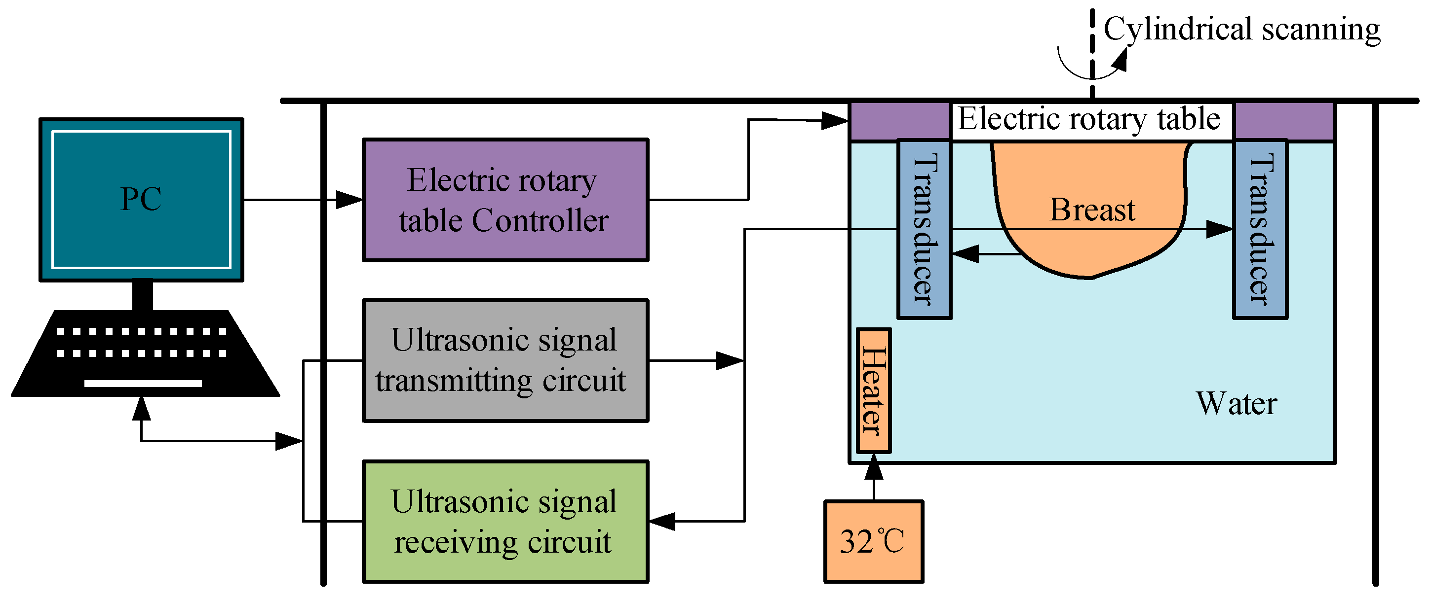
Figure 2.
Ultrasound imaging with cylindrical motion of linear arrays. (a) Transducer configuration scheme. (b) The dimensions of the linear array transducer. (c) Cylindrical scanning diagram.
Figure 2.
Ultrasound imaging with cylindrical motion of linear arrays. (a) Transducer configuration scheme. (b) The dimensions of the linear array transducer. (c) Cylindrical scanning diagram.
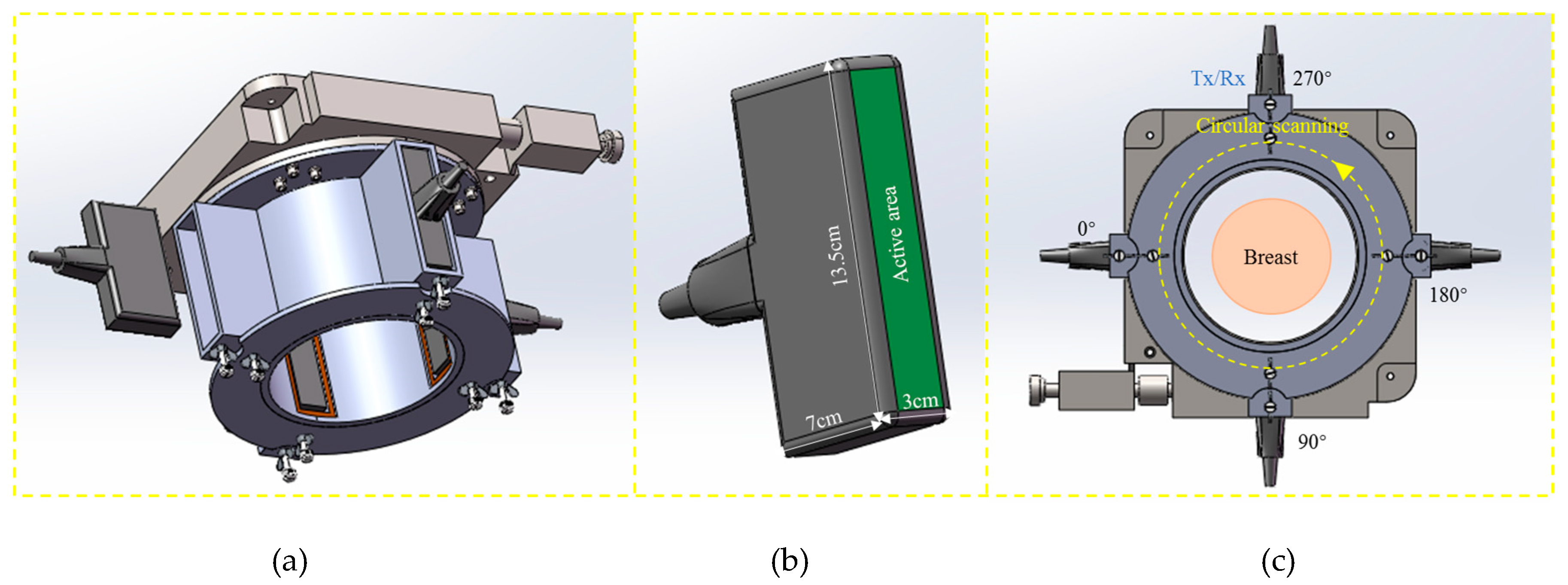
Figure 3.
Frequency property of the ultrasound transducer. (a) Sensitivity. (b) Fractional bandwidth.
Figure 3.
Frequency property of the ultrasound transducer. (a) Sensitivity. (b) Fractional bandwidth.
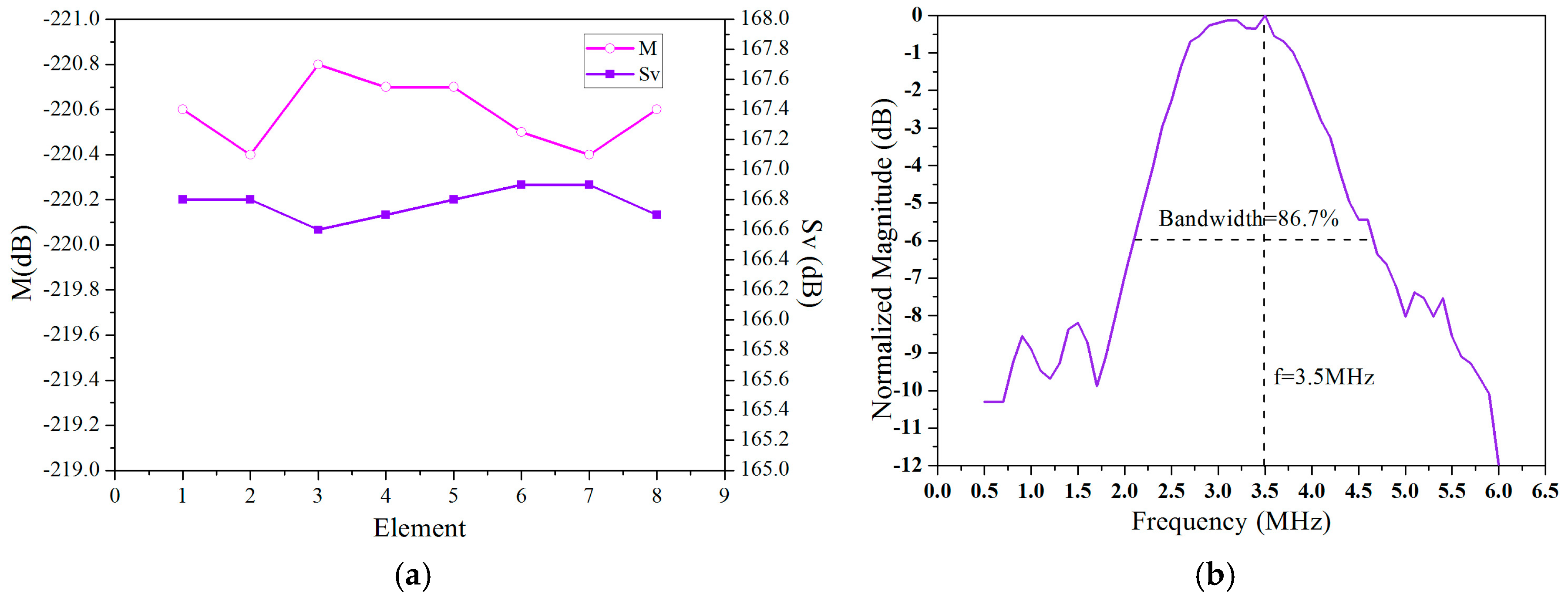
Figure 4.
Multi-perspective breast ultrasound imaging. (a) Vertical slice (b) Horizontal slice. (c) 3D imaging.
Figure 4.
Multi-perspective breast ultrasound imaging. (a) Vertical slice (b) Horizontal slice. (c) 3D imaging.
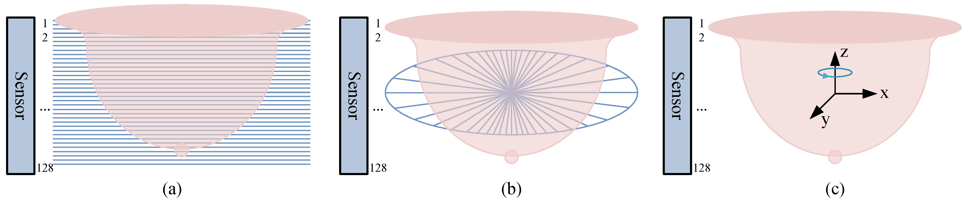
Figure 5.
Calculation of the focusing delay time τ for the linear array transducer.
Figure 6.
Focusing delay data τj(F, βj) of each channel.
Figure 7.
(a) Experimental setup. (b) PC workstation. (c) 64 channel ultrasonic signal receiving and transmitting circuits. (d) Diagram of the clinical imaging.
Figure 7.
(a) Experimental setup. (b) PC workstation. (c) 64 channel ultrasonic signal receiving and transmitting circuits. (d) Diagram of the clinical imaging.

Figure 8.
Ultrasonic tomography using this setup. (a) The whole breast model imaging. (b) The upper part of the breast imaging. (c) The lower part of the breast imaging. (d) Breast model.
Figure 8.
Ultrasonic tomography using this setup. (a) The whole breast model imaging. (b) The upper part of the breast imaging. (c) The lower part of the breast imaging. (d) Breast model.

Figure 9.
Ultrasonic horizonal tomography images using this setup. (a) Slice N = 2. (b) Slice N = 15. (c) Slice N = 25. (d) Slice N = 40. (e) Slice N = 50. (f) Slice N = 72.
Figure 9.
Ultrasonic horizonal tomography images using this setup. (a) Slice N = 2. (b) Slice N = 15. (c) Slice N = 25. (d) Slice N = 40. (e) Slice N = 50. (f) Slice N = 72.
Figure 10.
Ultrasonic vertical tomography images using this setup. (a) Angle = 24°. (b) Angle = 64°. (c) Angle = 96°. (d) Angle = 164°. (e) Angle = 196°. (f) Angle = 258°.
Figure 10.
Ultrasonic vertical tomography images using this setup. (a) Angle = 24°. (b) Angle = 64°. (c) Angle = 96°. (d) Angle = 164°. (e) Angle = 196°. (f) Angle = 258°.
© 2019 by the authors. Licensee MDPI, Basel, Switzerland. This article is an open access article distributed under the terms and conditions of the Creative Commons Attribution (CC BY) license (http://creativecommons.org/licenses/by/4.0/).
Share and Cite
MDPI and ACS Style
Liu, C.; Zhang, B.; Xue, C.; Zhang, W.; Zhang, G.; Cheng, Y. Multi-Perspective Ultrasound Imaging Technology of the Breast with Cylindrical Motion of Linear Arrays. Appl. Sci. 2019, 9, 419. https://doi.org/10.3390/app9030419
AMA Style
Liu C, Zhang B, Xue C, Zhang W, Zhang G, Cheng Y. Multi-Perspective Ultrasound Imaging Technology of the Breast with Cylindrical Motion of Linear Arrays. Applied Sciences. 2019; 9(3):419. https://doi.org/10.3390/app9030419
Chicago/Turabian StyleLiu, Chang, Binzhen Zhang, Chenyang Xue, Wendong Zhang, Guojun Zhang, and Yijun Cheng. 2019. "Multi-Perspective Ultrasound Imaging Technology of the Breast with Cylindrical Motion of Linear Arrays" Applied Sciences 9, no. 3: 419. https://doi.org/10.3390/app9030419
Note that from the first issue of 2016, this journal uses article numbers instead of page numbers. See further details here.