Defects Detection and Localization in Underwater Plates Using Laser Laterally Generated Pure Non-Dispersive S0 Mode


1
School of Science, Nanjing University of Science and Technology, Nanjing 210094, China
2
School of Electronic and Optical Engineering, Nanjing University of Science and Technology, Nanjing 210094, China
3
MIIT Key Laboratory of Advanced Solid Laser, Nanjing University of Science and Technology, Nanjing 210094, China
*
Author to whom correspondence should be addressed.
†
These authors contributed equally to this work.
Appl. Sci. 2019, 9(3), 459; https://doi.org/10.3390/app9030459
Submission received: 26 December 2018
/
Revised: 12 January 2019
/
Accepted: 12 January 2019
/
Published: 29 January 2019
(This article belongs to the Special Issue Laser Ultrasonics)
Abstract
:Featured Application
This study provides a non-contact method of defect detection and localization in underwater plates using pure S0 mode of Lamb wave with small dispersion generated by laterally distributed laser source.
Abstract
When working in humid environments, corrosion defects are easily produced in metallic plates. For defect detection in underwater plates, symmetric modes of Lamb waves are widely used because of their characteristics including long propagating distance and high sensitivity to defects. In this study, we extend our previous work by applying the laser laterally generated S0 mode to detection and localization of defects represented by artificial notches in an aluminum plate immersed in water. Pure non-dispersive S0 mode is generated in an underwater plate by lateral laser source irradiation and its fd (frequency·thickness) range is selected by theoretical calculation. Using this lateral excitation, the S0 mode is enhanced; meanwhile, the A0 mode is effectively suppressed. The mode-converted A0 mode from the incident S0 mode is used to detect and localize the defect. The results reveal a significantly improved capability to detect defects in an underwater plate using the laser laterally generated S0 mode, while that using A0 is limited due to its high attenuation. Furthermore, owing to the long propagating distance and the non-dispersion characteristics of the S0 generated by the lateral laser source, multiple defects can also be detected and localized according to the mode conversion at the defects.
1. Introduction
Plate-like structures are now widely used in practical engineering applications such as boat/submarine hulls, offshore platforms, and underwater sensors. However, when working under water or in corrosive environments, these structures are prone to corrosion. Corrosion evolves into cracks and holes, commonly reducing the service life of the structures and leading to catastrophic consequences. Therefore, it is of great importance to regularly check the integrity of these structures. Many non-destructive testing techniques have been developed to identify damages in metallic structures, such as magnetic particle inspection [1,2], the magnetic flux leakage technique [3,4], pressure testing [5], and the ultrasonic guide wave technique [6]. However, these methods have been increasingly challenged in practical applications in real engineering structures, especially in underwater plates [7].
In plate-like structures, Lamb wave is a useful tool for analyzing the integrity of such structures because it has characteristics such as long propagation distance and low attenuation and, most importantly, it has a high sensitivity to defects [8,9,10,11,12,13,14]. Because of these characteristics, Lamb waves also have great potential in defect detection in underwater structures.
For traditional methods in defect detection, transducers are widely used to generate and receive Lamb waves in plates [15,16,17,18,19]. When working in underwater environments, the surrounding water acts as the coupling agent for transducers to couple the generated acoustic waves into plate. Antisymmetric Lamb modes are easily generated by placing the transducers on the surface of structures, and their amplitude can be measured accordingly. This antisymmetric Lamb wave mode can be directly used in practical applications such as the estimation of the plate thickness [20], detection of defects in underwater pipes [5], identification of corrosion damage in submerged metallic structures [6], etc. Meanwhile, due to characteristics such as low attenuation, symmetric modes, especially those at a specific fd range, are frequently used in evaluations of solid plates, such as in hidden defect detection [21], multiple defect detection [22], corrosion monitoring [23], imaging of immersed plates with defects [24], and so on. These symmetric modes of Lamb waves at a specific fd range can also be generated and detected by contact-transducers. However, to obtain proper transfer of energy from the transducers to the structure, the transducers need to be in contact with the surface, or very close to the sample. Moreover, the angle between the transducer and sample needs to be adjusted precisely to generate appropriate Lamb wave mode, which increases the difficulty in realizing this approach.
Because of these limitations of contact approaches, some researchers have used the laser ultrasound technique to develop a method for detecting underwater structures. Rizzo et al. [25] used a pulsed laser to generate Lamb waves, including both symmetric modes and antisymmetric modes, in an aluminum plate immersed in water, and used two immersed transducers for reception. Pistone et al. [26] used a similar technique to detect defects in underwater plate. In the study, Lamb waves were generated by a pulsed laser focusing on the surface of plate and were detected by an array of immersed transducers. Lee et al. [27] developed a noncontact laser ultrasonic propagation imaging (UPI) system for damage visualization of liquid-immersed structures using the A0 mode. When the generating laser irradiates the plate surface, both symmetric modes and antisymmetric modes can be generated, while the symmetric modes normally have small out-of-plane displacement because of the asymmetric excitation (the source is asymmetric with respect to the middle plane of the plate). By adjusting the detection transducer at the proper angle to maximize the sensitivity to the leaky S0 mode, the S0 mode with small dispersion and low amplitude can be detected, along with the A0 mode with large dispersion and high amplitude. When the propagating distance is not long enough, the S0 and A0 mode are not separated. In this case, the large wave packet of the A0 mode in the time domain caused by its strong dispersion may make it difficult to identify the S0 mode or other reflections [25,26]. In addition, using an optical method, e.g., laser deflectometry or interferometry, it is very difficult to detect the S0 mode generated by pulsed laser irradiation on the surface of plate. This is not only because of the interference introduced by the antisymmetric modes, but also because most of the interferometry and the deflectometry is only sensitive to out-of-plane displacement, while the S0 mode has low out-of-plane displacement, especially when it is generated by asymmetric excitation [13,27].
Our previous work presented a method to generate pure non-dispersive S0 mode using laser lateral generation in a thin aluminum plate in dry conditions [28]. Using this method, the S0 mode is enhanced and the A0 mode is restrained effectively. In this paper, we extend our previous work by combining the laser lateral generation method with an existing laser-based ultrasonic detection technique, and realizing detection and localization of bulk defect represented by an artificial notch in an aluminum plate immersed in water. First, pure S0 mode with low dispersion is generated by pulsed laser laterally irradiating on the side of the aluminum plate. A laser vibrometer is used to detect the out-of-plane displacement of the waves on the surface of the plate. The S0 mode at specific fd range is selected by calculating the dispersion curves and attenuation relation to ensure the lowest dispersion and attenuation. Then, an underwater aluminum plate with artificial notches was experimentally evaluated using laser laterally generated S0 mode; an experiment using A0 mode was also performed for comparison. Utilizing the mode conversion produced by the interaction between S0 mode and defect, the defect can be detected and localized. Furthermore, owing to the non-dispersion characteristics of the S0 generated by a lateral laser source, the multiple defects with short spatial intervals can also be detected and localized according to the mode conversion at each defect.
2. Materials and Methods
When a plate is immersed in water, the energy of the Lamb waves in the plate will leak into the water. This type of special Lamb wave is called a leaky Lamb wave. Different from the Lamb wave propagating in free plates, when the leaky Lamb wave meets the solid–water interface, part of the wave reflects back in the plate, while part of the wave crosses the solid–water interface and is transmitted into the surrounding water. The attenuation of Lamb waves depends strongly on the normal displacement during its propagation at the solid–water interface. Generally, symmetric modes can propagate for a longer distance, because it is difficult for the in-plane particle motion to cross the plate–water interface; therefore, the energy of the symmetric modes will mostly be constrained to the plate. On the other hand, as antisymmetric modes mainly have out-of-plane displacement, the energy will easily leak into the surrounding water and be converted into quasi-Scholte waves [29].
Since not all Lamb wave modes can propagate for a long distance in an underwater plate, it is of great importance to select the proper mode with long propagation distance and small dispersion for defect detection in underwater plate. Therefore, the dispersion curves of Lamb waves in the aluminum plate are calculated, the amplitude distributions of both A0 and S0 modes are analyzed, and the attenuation curves of both A0 and S0 modes are obtained in simulations. The results could provide the basis for mode selection in experimental measurements.
2.1. Mode Selection of Lamb Waves for Defect Detection in Underwater Plates
Figure 1 shows the dispersion curves of Lamb waves propagating in a free aluminum plate, which is calculated based on the Lamb wave dispersion equations [30]. In the region fd < 2 MHz·mm, only A0 and S0 modes can be generated, where the A0 mode has strong dispersion. The weak dispersion region of the S0 mode exists in the low-fd range around 1MHz·mm, as shown in the dotted frame in Figure 1. When the plate is fully immersed in water, the dispersion curves of S0 and A0 mode are almost invariant [27,31]. The energy of A0 mode partly converts into a Scholte wave, which decreases exponentially away from the surface into water. Utilizing the dispersion equations, the displacement components of both S0 and A0 modes in the plate are also calculated, and the normalized amplitudes at 1 MHz·mm are shown in Figure 2.
In Figure 2, ux and uz represent the normalized in-plane and out-of-plane displacement in a plate with thickness d, respectively. Clearly, the out-of-plane component of the S0 mode is much smaller than its in-plane component. However, the A0 mode is the opposite, having a higher out-of-plane component than its in-plane component. The high out-of-plane displacement of the A0 mode at the surface of plate leads to a significant attenuation in underwater plate, and thus will significantly limit its propagation distance.
The attenuation curves are calculated using the finite element method (FEM) software COMSOL® in a 2D model for mode selection [32,33,34]. Considering an aluminum plate with a thickness of 0.2 mm and a length of 150 mm, all boundaries are in contact with water whose thickness is 0.5 mm. The outside of the water layer is set to be outwardly radiative, so that it can be considered as infinite water. The interface between the water and the aluminum plate is simulated using the acoustic structure-coupling boundary condition. The material properties of aluminum and water used are shown in Table 1. The aluminum plate and water layer are meshed by quadrangle elements. To ensure the accuracy of simulation, the maximum of the quadrangle elements is less than Le = 80 μm, guaranteeing that at least 8 elements are allocated per wavelength [35]. In the water layer, acoustic pressure is only applied in the y-axis, as shown in Figure 3, because fluid is unable to withstand shear loads in the x-axis. The interface between the water layer and the aluminum plate is simulated using an acoustic-structure boundary provided by COMSOL®. This coupling constraint ensures that the motions of particles at the interface are continuous. The simulation is carried out in the frequency domain for fd varying from 0.5 to 1.5 MHz·mm. For precise excitation at the corresponding fd, the generation of both S0 and A0 mode are simulated by loading the displacements at the left side of aluminum plate, including in-plane and out-of-plane components, at each specific fd.
2.2. Sample and Experimental Setup
The schematic diagram of the sample is shown in Figure 4. A pulsed Nd:YAG laser produces a series of laser pulses with a temporal width of ~10 ns at a wavelength of 1064 nm. The laser is focused into a circular spot at a diameter of ~0.2 mm on the plate as the pump laser. The Lamb wave is generated in a thermoelastic mechanism with a maximum pulse energy of ~0.5 mJ. A laser vibrometer (wavelength 632.8 nm) is used as the detection mechanism; its output laser is focused on the upper surface of the plate as a probe laser, which is used to detect the out-of-plane displacement of Lamb waves. The sample is fully immersed in a glass water tank. The water layer is thick enough to reduce the influence of vibration or reflection from the edge of the tank. In Figure 4, ‘PS0’ represents the position of the pump laser for enhanced S0 mode generation (described as ‘lateral generation configuration’). In this configuration, the pump laser is focused to a diameter similar in size to the plate thickness after collimation, and the side of plate is irradiated vertically. Meanwhile, the pump laser is adjusted by stepper motor and focused to an appropriate position that is symmetric to the side of the plate, so as to generate the S0 mode and restrain the A0 mode. For comparison, the conventional laser-based A0-mode-dominant generation is also examined by focusing the pump laser at ‘PA0’ on the upper surface of the plate (described as ‘top generation configuration’). As a result, the out-of-plane displacement of the generated A0 mode is significantly larger than that of the S0 mode generated at the same time, so that the out-of-plane displacement of the S0 mode can be ignored.
The sample is an aluminum plate with a thickness of ~0.2 mm and a surface area of 150 × 100 mm2. In experimental measurements, the center frequency of Lamb waves generated by the pulsed laser is ~5 MHz. The thickness is chosen to generate the S0 mode of Lamb wave at 1 MHz·mm, utilizing the dispersion curve shown in Figure 1. The artificial notch (~0.5 mm width on the x-axis, ~0.1 mm depth on the z-axis, and ~20 mm on the y-axis) is located 40 mm away from the left side of the plate, where the lateral generation source “PS0” is located. In the top generation configuration, the generation laser spot, indicated by ‘PA0’, is ~40 mm away from the notch, as shown in Figure 4. In both the lateral and top generation configurations, the probe laser is focused on the upper surface of the plate in order to obtain the out-of-plane displacement of the Lamb waves. If the length of the artificial notch in the y direction is long enough, B-scan images can be extracted by scanning the probe laser along the x-axis near the center of the notch (blue stripe), as indicated by the yellow stripe shown in Figure 4.
3. Results
The experiments are carried out firstly on a plate with an artificial notch, as shown in Figure 4, using the top generation configuration. A scan of the probe laser from ‘PA0’ toward the position of the projection of the notch (the blue stripe in Figure 4) at the upper surface along the x-axis in a scanning step of 0.5 mm is achieved, and the result is shown in Figure 5a. Because of the surrounding water, the amplitude of the A0 mode decays very fast. Its amplitude is significantly attenuated to be lower than 1/5 of the incident A0 mode after a propagating distance of ~17 mm. It can also be seen that after propagating a short distance, part of the A0 mode is converted into a quasi-Scholte wave, as shown in Figure 5a. The color range is adjusted to a small degree, to show the A0 mode and Scholte wave with a small amplitude; therefore, the A0 mode with high amplitude (~1.6 V) at the beginning is saturated in this scale. However, even in a very small display range, neither the S0 mode, nor the reflection of A0 mode from the notch, can be observed. Furthermore, due to the strong dispersions of both A0 mode and the converted Scholte wave, it is difficult to distinguish these waves in the time domain. For these reasons, the A0 mode is not suitable for long-range detection in underwater plates.
Then, the experiment was repeated using the lateral generation configuration with the same scanning step, and the results are shown in Figure 5b. As expected, the generated S0 mode at 1 MHz·mm is almost non-dispersive, and can propagate a significantly longer distance than the A0 mode. When the S0 mode propagates to the defect, part of the S0 mode is reflected (however, the amplitude is too weak to display in Figure 5b), and part of the S0 mode is transmmitted (marked by ‘tS0’ in Figure 5b). Additionally, mode conversion takes place at the defect, and part of the S0 mode is converted into the A0 mode in this fd range. The converted A0 mode from the S0 mode is reflected and transmitted at the defect, marked by ‘S0-rA0’ and ‘S0-tA0’, respectively, as shown in Figure 5b. The reflected ‘S0-rA0’ wave can reveal the presence of a defect. Furthermore, it is worth pointing out that as the plate thickness changes at the notch, the displacement distribution of the incident wave changes. The S0 mode couples with the other modes reflected between the edges of notch, leading to a short resonance at the notch, as shown in the dotted frame in Figure 5b. The short resonance with high out-of-plane displacement is also of benefit for defect localization in underwater plate.
Afterwards, acoustic wave signals obtained at 5 different locations during the approach of the probe to the vicinity of the defect projection on the upper sample surface (4 locations far away, and 1 location in the vicinity of the defect projection on the upper sample surface) are shown in Figure 5c. Generally, when the pulsed laser irradiating the side of plate, the laser spot cannot be perfectly symmetric with respect to the middle plane of the sample side surface, so the A0 mode is excited along with the S0 mode. Even so, the surrounding water can efficiently eliminate any unwanted A0 modes. Within the travelling distance of ~20 mm, the S0 mode and the A0 mode do not separate in the time domain, and the wave packet (the signal of black line in Figure 5c) exhibits strong dispersion, where A0 mode has not disappeared completely. As the propagating distance increases (the red, blue and green lines in Figure 5c), the incident A0 mode with strong dispersion disappears, leaving the non-dispersive S0 mode and the reflected A0 mode resulting from mode conversion (marked as ‘S0-rA0’). When the S0 mode propagates a distance of 40 mm, i.e., when it arrives at the edge of the defect (shown by the purple line in Figure 5c), the amplitude of the wave is increased because of the overlapping of the incident S0 mode and the converted A0 mode.
This significant increase in wave amplitude from the near-field interactions of the S0 Lamb waves with the defects can be used to estimate the depth of hidden defects in dry condition [13]. However, due to the small out-of-plane displacement of the S0 mode and the dispersion of the A0 mode by the pulsed laser irradiating the surface, the width of the defect is hard to detect using the top generation configuration. On the other hand, by using the lateral generation configuration, the S0 mode is enhanced, and its non-dispersive characteristic leads to a narrow wave packet in the time domain, meanwhile the A0 mode is efficiently restrained. Therefore, the width of the notch can be estimated utilizing the lateral generation configuration, i.e., the probe system shown in Figure 4, but with a higher spatial resolution. By reducing the scanning step to 50 μm per step and focusing the probe laser onto a circular spot with a diameter of ~10 μm on the plate surface, the B-scan image at the defect area is obtained, and the result is shown in Figure 6a, with the corresponding peak-to-peak amplitude of the out-of-plane displacement being shown in Figure 6b. It can be seen that the amplitude decreases at both edges of the notch, the notch width of 0.4 ± 0.1 mm can be estimated by the scanning distance between the two troughs in Figure 6b.
4. Discussion
Using the 2D model described in Section 2.1, the attenuation coefficient α is calculated for fd ranging from 0.5 to 1.5 MHz·mm. The attenuation coefficient α is defined as Z1 = Z0·e−α·Δx, where Δx = x1 − x0, xi (i = 0,1) is the position of the two detection points, Zi (i = 0,1) is the out-of-plane displacement of the Lamb wave propagating in the plate. Figure 7a shows the normalized attenuation coefficients α·d of both S0 and A0 modes in the aluminum plate fully immersed in water. These calculated attenuation curves show good agreement with the results calculated by SAFE [31,36]. In the low-fd range from 0.5 to 1.5 MHz·mm, the attenuation of the A0 mode is much higher than that of the S0 mode. The attenuation of the S0 mode rises slowly at a quite low rate throughout the whole range; the coefficient of the A0 mode diminishes significantly before 0.8 MHz·mm and stabilizes at ~0.035. When fd = 1 MHz·mm, the attenuation of the A0 mode is about 15 times higher than that of the S0 mode. Figure 7b shows the signals at different positions in the underwater plate using the top generation configuration. The experimental attenuation coefficient α·d is ~0.0365 based on the fitted curve, which has good agreement with the simulation result.
According to Figure 5b,c, the S0 mode generated by lateral generation configuration has a narrow wave packet due to its low dispersion. Therefore, experiments are performed in an underwater plate with multiple defects, where the defects are very close to each other. The experiments are carried out using the lateral generation configuration, and the samples with multiple defects are shown in Figure 8. Figure 8a shows a plate with two artificial notches, and the interval between them is 10 mm. Figure 8b shows a plate with three artificial notches, with a 5 mm spatial interval between adjacent notches, as illustrated in the inset of Figure 8b. The notches are similar in size, with a width of ~0.5 mm on the x-axis and ~20 mm on the y-axis. The probe laser scans near the center of the notch, with a scanning step of 0.5 mm.
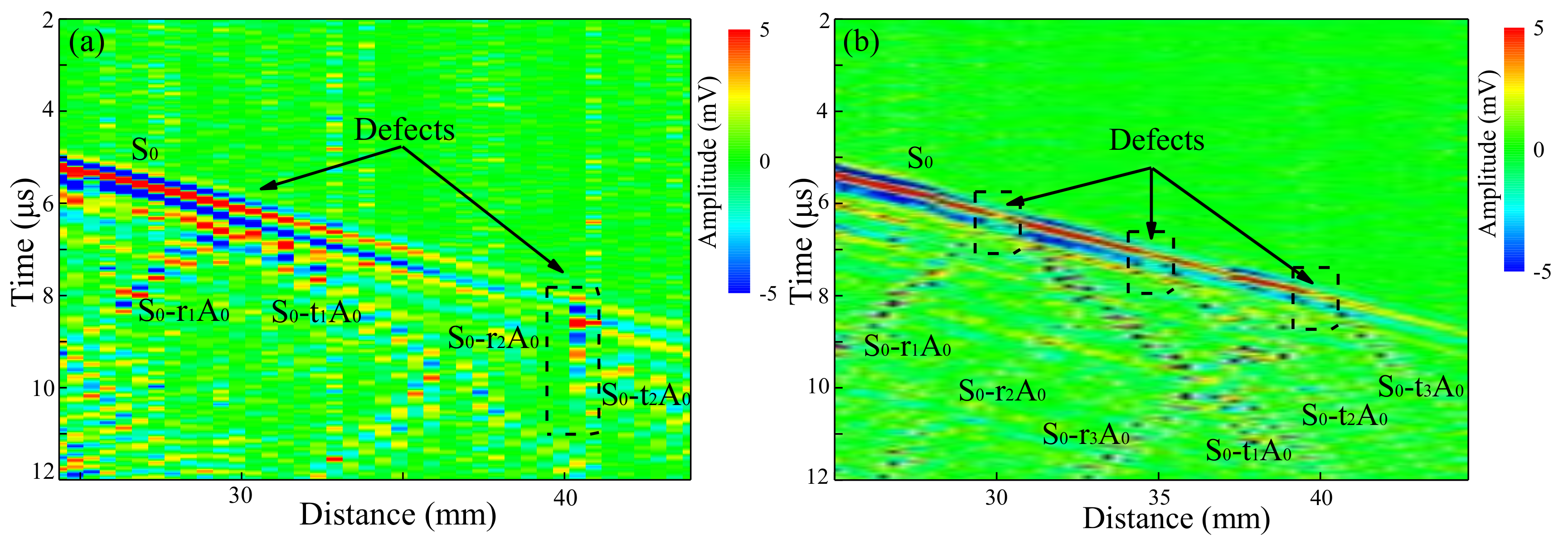
Figure 9a shows the B-scan image obtained in the plate with two notches. The reflection of S0 mode is too weak to be observed, but the mode-converted A0 mode is easily identified. The reflected and the transmitted mode-converted A0 at two notches are marked as ‘S0-riA0’ and ‘S0-tiA0’ (i = 1,2), respectively. The resonance at the defect is also observed, as shown in the dotted frame in Figure 9a, which helps to locate the second notch.
In Figure 9a, due to the lager velocity difference between the S0 mode and the A0 mode, the transmitted S0 mode and ‘S0-r1A0’ mode can be separated by a propagating distance of ~2 mm after interaction with the first notch. It is straightforward to extend the utilization of this technique to detect multiple defects with spatial intervals larger than ~2 mm, by identifying mode-conversions at each defect caused by the transmitted S0 mode. Therefore, the experiment on an underwater plate with three notches is conducted, in which the notches have the smaller spatial interval of ~5 mm between them, as shown in Figure 8b. Figure 9b shows the experimental results obtained in the aluminum plate shown in Figure 8b. The energy of the pump laser is increased compared to that in the previous experiment to enhance the transmission of the S0 mode after multiple notches. Mode conversions take place at three notches, as marked in Figure 9b. In Figure 9b, the mode of ‘S0-r2A0’ and ‘S0-t2A0’ is not clear, because of the shallow depth of the second notch. It is also worth noting that in the dotted frames in Figure 9b, the short resonance is not found. This is because the scanning step is approximately equal to the width of notch, while the resonance can only be detected when the probe laser is focused at the notch. However, as shown in Figure 6b, the amplitude decreases at the edges of the notch; this leads to the breakpoints in the dotted frames in Figure 9b. Because of the non-dispersion of the S0 mode and the difference between the S0 mode and the A0 mode in velocity, the three notches with the separations of 5 mm are clearly detected and localized.
According to the above results, it can be observed that the non-dispersive S0 generated by pulsed laser lateral irradiation of the side of the plate is suitable for inspection of underwater plates. The main features are as follows:
- (1)
- By using a laser ultrasonic technique for excitation and detection, the system can realize remote non-contact detection.
- (2)
- The S0 mode generated by lateral generation configuration has good SNR and can propagate a longer distance, while the amplitude of the A0 mode is significantly restrained.
- (3)
- The mode conversion can be an effective tool for defect detection and localization.
- (4)
- Because of the non-dispersion and narrow wave packet of the S0 mode using lateral generation configuration, defect width can be estimated, and multiple defects with short spatial intervals can be detected.
5. Conclusions
In conclusion, for defect detection in underwater plates, a non-contact method using laser ultrasonics is applied. The dispersion curves and attenuation relations of both A0 and S0 modes are calculated for mode selection. The specific S0 mode, with low dispersion and attenuation, is generated by pulsed laser, laterally irradiating the side of the plate symmetrically. The A0 mode is efficiently restrained, not only because of the symmetric lateral generation, but also because of the high attenuation caused by the surrounding water. The results show that the lateral laser source can generate non-dispersive S0 mode efficiently in underwater plate, and this specific S0 mode at 1 MHz·mm has good potential for defect detection and localization in underwater plates. The successful identification of multiple defects has been experimentally verified in a plate with multiple defects within a short spatial interval. This method could serve as an alternative approach for evaluating and quantifying the integrity of underwater plates.
Author Contributions
Conceptualization, Z.S.; Funding acquisition, C.N. and Z.S.; Investigation, Q.X.; Writing—original draft, Q.X.; Writing—review & editing, C.N. and Z.S.
Funding
This research was funded by National Natural Science Foundation of China, grant number 61627802, National Natural Science Foundation of China, grant number 61405093, Natural Science Foundation of Jiangsu Province, grant number, BK20140771 and Fundamental Research Funds for the Central Universities, grant number 30916014112-001.
Conflicts of Interest
The authors declare no conflict of interest.
References
- Nordbø, H. NDE—Overview and Legal Requirements. In Submersible Technology; Springer: Berlin, Germany, 1986; pp. 183–187. [Google Scholar]
- Bayliss, M.; Short, D.; Bax, M. Underwater Inspection; E & FN Spon: London, UK, 1988. [Google Scholar]
- Mandal, K.; Dufour, D.; Krause, T.W.; Atherton, D.L. Investigations of magnetic flux leakage and magnetic Barkhausen noise signals from pipeline steel. J. Phys. D 1997, 30, 962. [Google Scholar] [CrossRef]
- Udpa, L.; Mandayam, S.; Udpa, S.; Sun, Y.; Lord, W. Developments in gas pipeline inspection technology. Mater. Eval. 1996, 54, 4. [Google Scholar]
- Na, W.B.; Kundu, T. Underwater Pipeline Inspection Using Guided Waves. J. Press. Vessel Technol. 2002, 124, 196–200. [Google Scholar] [CrossRef]
- Chen, J.; Su, Z.; Cheng, L. Identification of corrosion damage in submerged structures using fundamental anti-symmetric Lamb waves. Smart Mater. Struct. 2010, 19, 015004. [Google Scholar] [CrossRef]
- Rizzo, P. NDE/SHM of Underwater Structures: A Review; Trans Tech Publications: Princeton, NJ, USA, 2013; pp. 208–216. [Google Scholar]
- Ghosh, T.; Kundu, T.; Karpur, P. Efficient use of Lamb modes for detecting defects in large plates. Ultrasonics 1998, 36, 791–801. [Google Scholar] [CrossRef]
- Kessler, S.S.; Spearing, S.M.; Soutis, C. Damage detection in composite materials using Lamb wave methods. Smart Mater. Struct. 2002, 11, 269. [Google Scholar] [CrossRef]
- Tua, P.; Quek, S.; Wang, Q. Detection of cracks in plates using piezo-actuated Lamb waves. Smart Mater. Struct. 2004, 13, 643. [Google Scholar] [CrossRef]
- Kim, H.; Jhang, K.; Shin, M.; Kim, J. A noncontact NDE method using a laser generated focused-Lamb wave with enhanced defect-detection ability and spatial resolution. Ndt E Int. 2006, 39, 312–319. [Google Scholar] [CrossRef]
- Jhang, K.-Y.; Shin, M.J.; Lim, B.O. Application of the laser generated focused-Lamb wave for non-contact imaging of defects in plate. Ultrasonics 2006, 44, e1265–e1268. [Google Scholar] [CrossRef]
- Clough, A.; Edwards, R. Characterisation of hidden defects using the near-field ultrasonic enhancement of Lamb waves. Ultrasonics 2015, 59, 64–71. [Google Scholar] [CrossRef] [Green Version]
- Achenbach, J. Wave Propagation in Elastic Solids; Elsevier: Amsterdam, The Netherlands, 2012; Volume 16. [Google Scholar]
- Alleyne, D.N.; Cawley, P. The interaction of Lamb waves with defects. IEEE Trans. Ultrason. Ferroelectr. Freq. Control 1992, 39, 381–397. [Google Scholar] [CrossRef] [PubMed]
- Giurgiutiu, V. Lamb wave generation with piezoelectric wafer active sensors for structural health monitoring. In Proceedings of the Smart Structures and Materials 2003: Smart Structures and Integrated Systems, San Diego, CA, USA, 3–6 March 2003; pp. 111–123. [Google Scholar]
- Lemistre, M.; Balageas, D. Structural health monitoring system based on diffracted Lamb wave analysis by multiresolution processing. Smart Mater. Struct. 2001, 10, 504. [Google Scholar] [CrossRef]
- Diligent, O.; Grahn, T.; Boström, A.; Cawley, P.; Lowe, M.J. The low-frequency reflection and scattering of the S0 Lamb mode from a circular through-thickness hole in a plate: Finite Element, analytical and experimental studies. J. Acoust. Soc. Am. 2002, 112, 2589–2601. [Google Scholar] [CrossRef] [PubMed]
- Lowe, M.J.; Diligent, O. Low-frequency reflection characteristics of the s0 Lamb wave from a rectangular notch in a plate. J. Acoust. Soc. Am. 2002, 111, 64–74. [Google Scholar] [CrossRef]
- Moilanen, P.; Nicholson, P.; Kilappa, V.; Cheng, S.; Timonen, J. Measuring guided waves in long bones: Modeling and experiments in free and immersed plates. Ultrasound Med. Biol. 2006, 32, 709–719. [Google Scholar] [CrossRef]
- Bagheri, A.; Rizzo, P. Guided ultrasonic wave testing of an immersed plate with hidden defects. Opt. Eng. 2015, 55, 011003. [Google Scholar] [CrossRef]
- Gao, G.; Deng, M.; Li, M.; Pei, J. Mode selection of Lamb waves for the evaluation of solid plates with liquid loading. Sci. China Phys. Mech. Astron. 2014, 57, 1840–1847. [Google Scholar] [CrossRef]
- Sharma, S.; Mukherjee, A. Ultrasonic guided waves for monitoring corrosion in submerged plates. Struct. Control Health Monit. 2015, 22, 19–35. [Google Scholar] [CrossRef]
- Takiy, A.E.; Kitano, C.; Higuti, R.T.; Granja, S.C.; Prado, V.T.; Elvira, L.; Martínez-Graullera, O. Ultrasound imaging of immersed plates using high-order Lamb modes at their low attenuation frequency bands. Mech. Syst. Signal Process. 2017, 96, 321–332. [Google Scholar] [CrossRef]
- Rizzo, P.; Han, J.-G.; Ni, X.-L. Structural health monitoring of immersed structures by means of guided ultrasonic waves. J. Intell. Mater. Syst. Struct. 2010, 21, 1397–1407. [Google Scholar] [CrossRef]
- Pistone, E.; Li, K.; Rizzo, P. Noncontact monitoring of immersed plates by means of laser-induced ultrasounds. Struct. Health Monit. 2013, 12, 549–565. [Google Scholar] [CrossRef]
- Lee, J.R.; Jang, J.K.; Kong, C.W. Fully Noncontact Wave Propagation Imaging in an Immersed Metallic Plate with a Crack. Shock Vib. 2014, 2014, 895693. [Google Scholar] [CrossRef]
- Xie, Q.; Yan, S.; Lu, J.; Ni, C.; Ni, X.; Shen, Z. Defect Detection Using the Lamb Mode S0 by Pulsed Laser Laterally Illuminating on a Side of the Plate. Int. J. Thermophys. 2018, 39, 123. [Google Scholar] [CrossRef]
- Cegla, F.B.; Cawley, P.; Lowe, M.J.S. Material property measurement using the quasi-Scholte mode—A waveguide sensor. J. Acoust. Soc. Am. 2005, 117, 1098–1107. [Google Scholar] [CrossRef]
- Rose, J.L. Ultrasonic Guided Waves in Solid Media; Cambridge University Press: Cambridge, UK, 2014. [Google Scholar]
- Hayashi, T.; Inoue, D. Calculation of leaky Lamb waves with a semi-analytical finite element method. Ultrasonics 2014, 54, 1460–1469. [Google Scholar] [CrossRef] [PubMed]
- Mirahmadi, S.J.; Honarvar, F. Application of signal processing techniques to ultrasonic testing of plates by S0 Lamb wave mode. NDT E Int. 2011, 44, 131–137. [Google Scholar] [CrossRef]
- Chen, L.; Dong, Y.; Meng, Q.; Liang, W. FEM simulation for Lamb Wave evaluate the defects of plates. In Proceedings of the 2012 International Workshop on Microwave and Millimeter Wave Circuits and System Technology, Chengdu, China, 19–20 April 2012; pp. 1–4. [Google Scholar]
- Ghadami, A.; Behzad, M.; Mirdamadi, H.R. A mode conversion-based algorithm for detecting rectangular notch parameters in plates using Lamb waves. Arch. Appl. Mech. 2015, 85, 793–804. [Google Scholar] [CrossRef]
- Alleyne, D.N.; Lowe, M.J.S.; Cawley, P. The Reflection of Guided Waves from Circumferential Notches in Pipes. J. Appl. Mech. 1998, 65, 635–641. [Google Scholar] [CrossRef]
- Inoue, D.; Hayashi, T. Transient analysis of leaky Lamb waves with a semi-analytical finite element method. Ultrasonics 2015, 62, 80–88. [Google Scholar] [CrossRef] [PubMed]
Figure 1.
Dispersion curves of Lamb waves in a free aluminum plate.
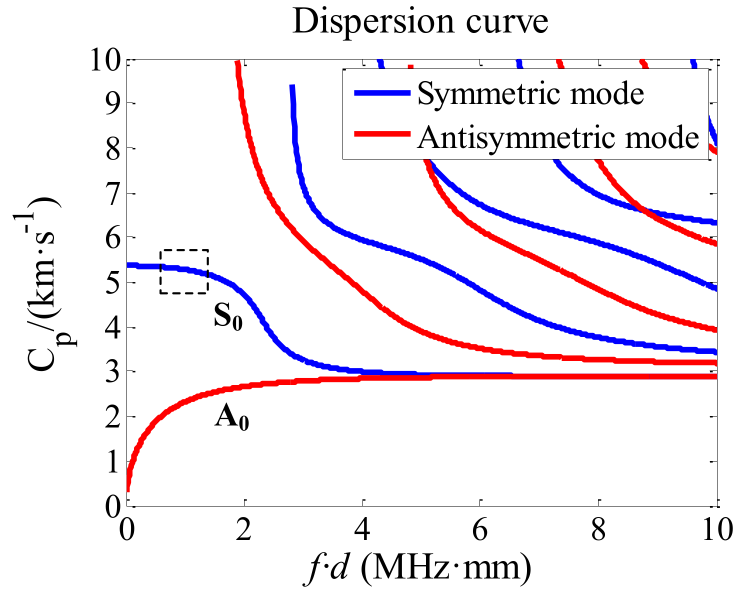
Figure 2.
Normalized displacement components of Lamb waves in the plate of thickness d: (a) the S0 mode; (b) the A0 mode.
Figure 2.
Normalized displacement components of Lamb waves in the plate of thickness d: (a) the S0 mode; (b) the A0 mode.

Figure 3.
Schematic of 2D model: aluminum plate underwater.
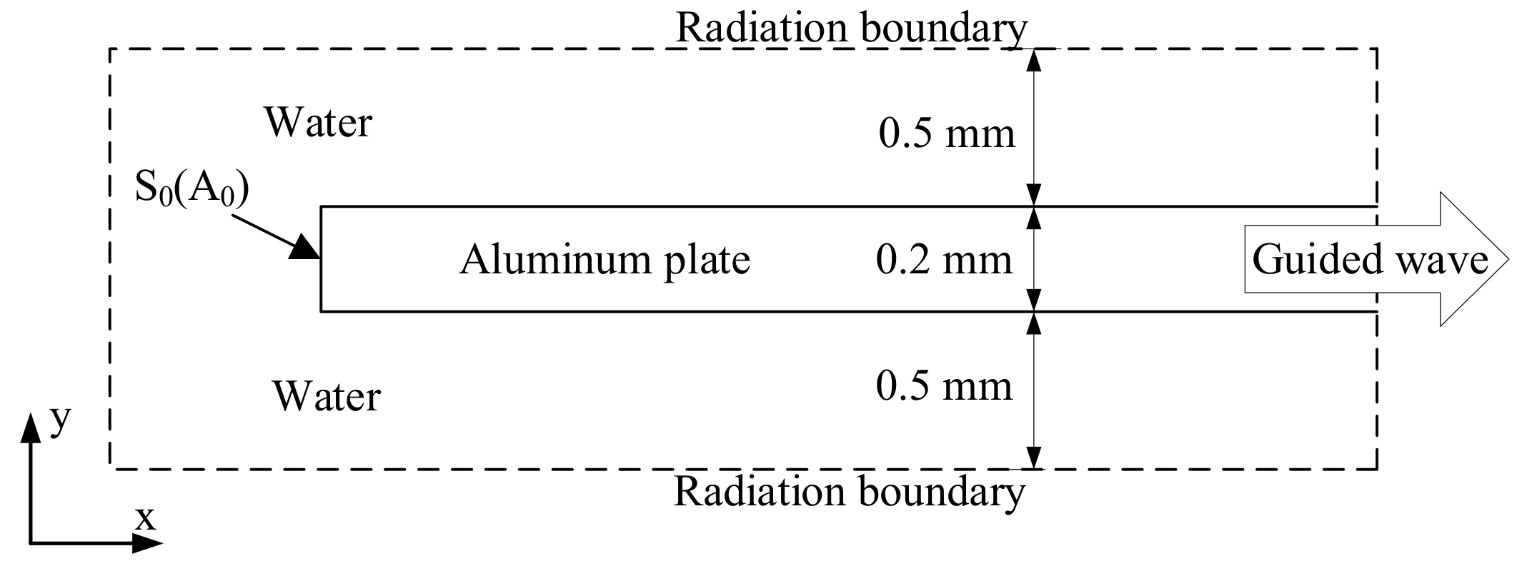
Figure 4.
Aluminum plate sample with an artificial notch at the lower surface; the blue stripe indicates the position of probe laser on the y-axis.
Figure 4.
Aluminum plate sample with an artificial notch at the lower surface; the blue stripe indicates the position of probe laser on the y-axis.
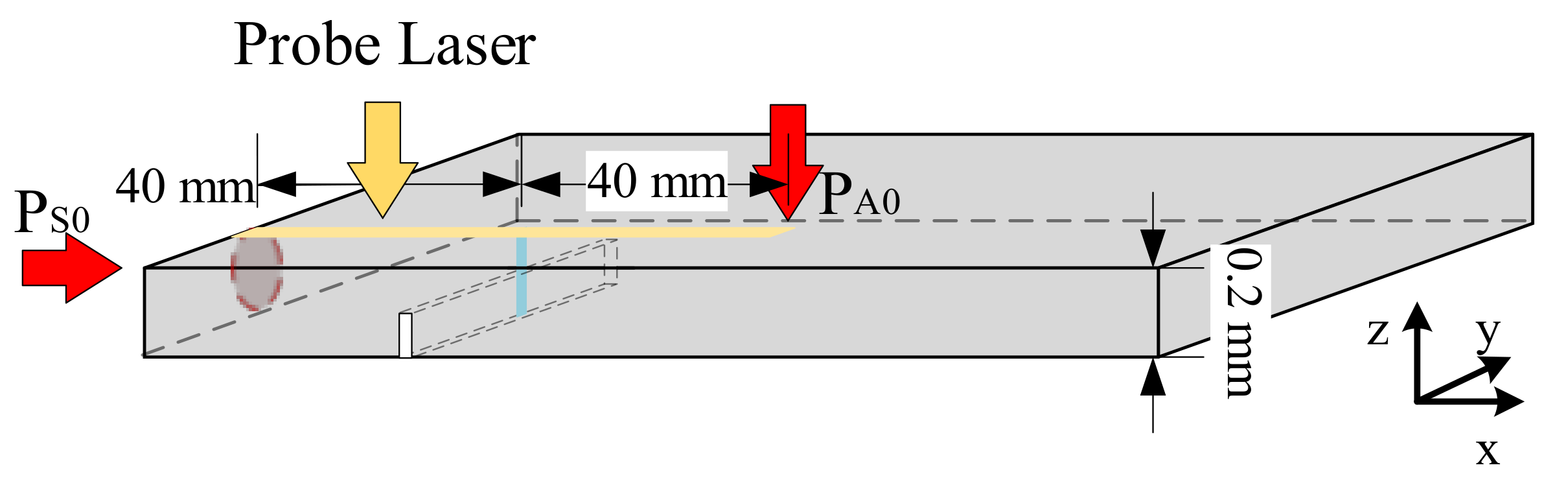
Figure 5.
(a) B-scan image using the top generation configuration on the underwater plate; (b) B-scan image of lateral generation configuration in the underwater plate; (c) time domain signal of different positions using the lateral generation configuration.
Figure 5.
(a) B-scan image using the top generation configuration on the underwater plate; (b) B-scan image of lateral generation configuration in the underwater plate; (c) time domain signal of different positions using the lateral generation configuration.

Figure 6.
(a) B-scan image at the defect with scanning step of 0.05 mm; (b) Amplitude at the corresponding position.
Figure 6.
(a) B-scan image at the defect with scanning step of 0.05 mm; (b) Amplitude at the corresponding position.
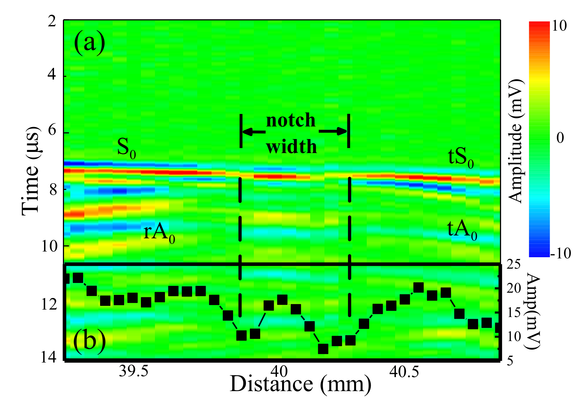
Figure 7.
(a) Normalized attenuation curves for A0 and S0 modes in the underwater aluminum plate; (b) Time domain signal at different positions using the top generation configuration.
Figure 7.
(a) Normalized attenuation curves for A0 and S0 modes in the underwater aluminum plate; (b) Time domain signal at different positions using the top generation configuration.
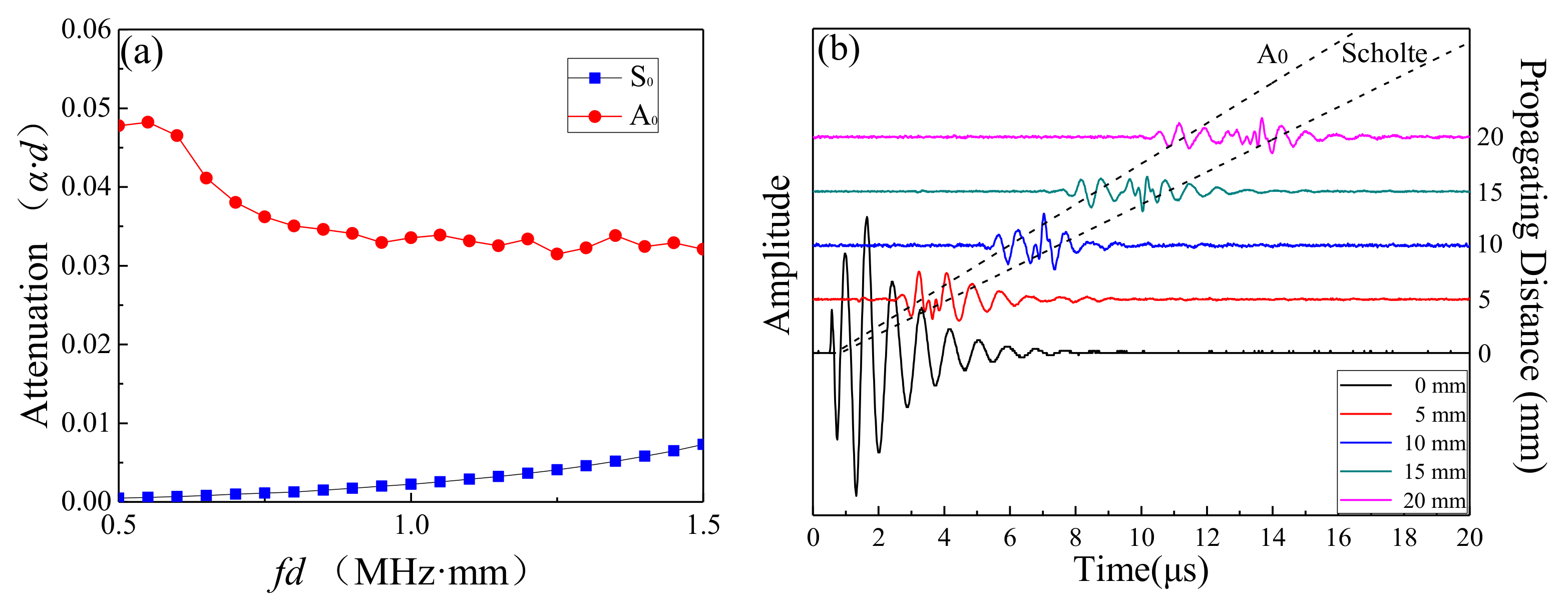
Figure 8.
Configuration of the aluminum plate, the blue stripe indicates the position of probe laser on the y-axis: (a) two artificial notches with an interval of 10 mm; (b) three artificial notches with an interval of 5 mm (the inset is the enlargement of the notches in the x-z plane).
Figure 8.
Configuration of the aluminum plate, the blue stripe indicates the position of probe laser on the y-axis: (a) two artificial notches with an interval of 10 mm; (b) three artificial notches with an interval of 5 mm (the inset is the enlargement of the notches in the x-z plane).
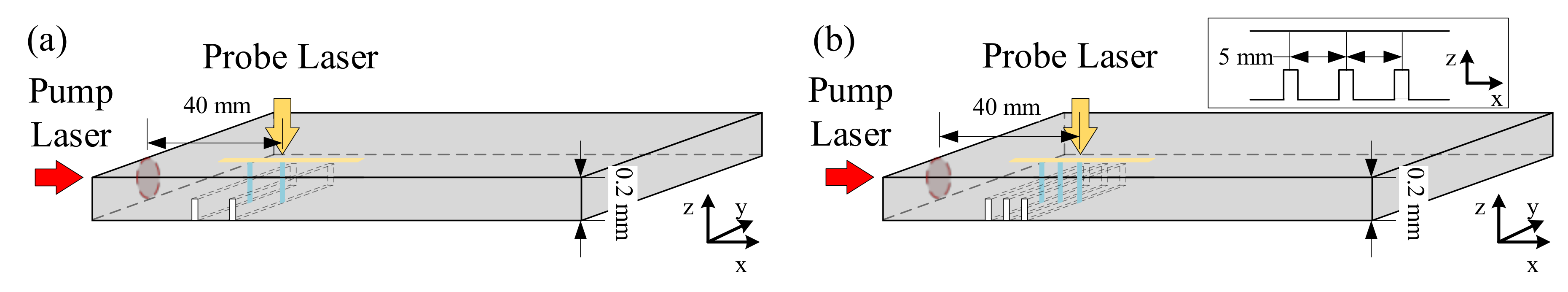
Figure 9.
B-scan images of underwater plate with multiple defects: (a) two notches; (b) three notches.
Figure 9.
B-scan images of underwater plate with multiple defects: (a) two notches; (b) three notches.


Table 1.
Material properties of aluminum and water used in the simulation and experimental measurements.
Table 1.
Material properties of aluminum and water used in the simulation and experimental measurements.
| Density (kg/m3) | CT (km/s) | CL (km/s) | Young’s Modulus GPa | |
|---|---|---|---|---|
| Aluminum | 2700 | 3103 | 6176 | 70 |
| Water | 1000 |
© 2019 by the authors. Licensee MDPI, Basel, Switzerland. This article is an open access article distributed under the terms and conditions of the Creative Commons Attribution (CC BY) license (http://creativecommons.org/licenses/by/4.0/).
Share and Cite
MDPI and ACS Style
Xie, Q.; Ni, C.; Shen, Z. Defects Detection and Localization in Underwater Plates Using Laser Laterally Generated Pure Non-Dispersive S0 Mode. Appl. Sci. 2019, 9, 459. https://doi.org/10.3390/app9030459
AMA Style
Xie Q, Ni C, Shen Z. Defects Detection and Localization in Underwater Plates Using Laser Laterally Generated Pure Non-Dispersive S0 Mode. Applied Sciences. 2019; 9(3):459. https://doi.org/10.3390/app9030459
Chicago/Turabian StyleXie, Qingnan, Chenyin Ni, and Zhonghua Shen. 2019. "Defects Detection and Localization in Underwater Plates Using Laser Laterally Generated Pure Non-Dispersive S0 Mode" Applied Sciences 9, no. 3: 459. https://doi.org/10.3390/app9030459
Note that from the first issue of 2016, this journal uses article numbers instead of page numbers. See further details here.