A Cross-Dichroic-Prism-Based Multi-Perspective Digital Image Correlation System


1
School of Instrument Science and Opto-electronics Engineering, Hefei University of Technology, Hefei 230009, China
2
Department Mechanical Engineering, Oakland University, Rochester, MI 48309, USA
*
Author to whom correspondence should be addressed.
Appl. Sci. 2019, 9(4), 673; https://doi.org/10.3390/app9040673
Submission received: 31 December 2018
/
Revised: 26 January 2019
/
Accepted: 4 February 2019
/
Published: 16 February 2019
(This article belongs to the Special Issue Advances in Digital Image Correlation (DIC))
Abstract
:Featured Application
A 3D-DIC system based on a single 3CCD color camera and a cross dichroic prism is proposed in this paper, this system can be applied to situations where three cameras are required for DIC measurement.
Abstract
A robust three-perspective digital image correlation (DIC) system based on a cross dichroic prism and single three charge-coupled device (3CCD) color cameras is proposed in this study. Images from three different perspectives are captured by a 3CCD camera using the cross dichroic prism and two planar mirrors. These images are then separated by different CCD channels to perform correlation calculation with an existing multi-camera DIC algorithm. The proposed system is considerably more compact than the conventional multi-camera DIC system. In addition, the proposed system has no loss of spatial resolution compared with the traditional single-camera DIC system. The principle and experimental setup of the proposed system is described in detail, and a series of tests is performed to validate the system. Experimental results show that the proposed system performs well in displacement, morphology, and strain measurement.
1. Introduction
Digital image correlation (DIC) technology was proposed in the 1980s [1,2]. As a robust, noncontact, full-field, and high-precision measurement method, this technology is not sensitive to the measurement environment. Thus, this method has been successfully applied to measure displacement and strain in most cases. The DIC method, especially 3D-DIC, has been extended to numerous research fields by researchers [3,4,5,6]. Therefore, DIC has become an important method in the field of experimental mechanics [7,8,9,10]. Traditional 3D-DIC technology obtains images by using two black and white charge-coupled devices (CCDs) or complementary metal oxide semiconductor (CMOS) cameras. A dual-camera system meets the measurement requirements in most cases. However, due to limitations in the field of view, it is difficult to obtain satisfactory results by using a dual-camera system if a multi-angle analysis is required. Therefore, researchers use multiple cameras to perform DIC measurements. The multi-camera system provides an obvious advantage over the traditional dual-camera system, in that it can cover a large area of measurement and thereby expand the measurement range DIC offers. In addition, for measurement areas with complex profiles, the multi-camera system can effectively reduce errors. However, DIC images are always obtained using expensive industrial cameras. For the dual- and multi-camera system, a trigger device must be added in the system in order to meet the required image acquisition synchronization. However, all these factors increase the measurement cost.
In recent years, researchers have proposed different methods for 3D-DIC measurement using a single camera. These methods can be mainly divided into two categories. The first divides the camera CCD into two parts, wherein the images of two different angles of the object are presented in two parts of the CCD with the aid of the designed optical path. Pankow proposed a four-mirror adapter-assisted single-camera 3D-DIC system to measure full-field out-of-plane displacement histories at high frame rates [11]. Genovese used a compact system of a biprism and a camera to perform stereo-DIC measurement [12]. Barone used two planar mirrors and a low-frame-rate camera to measure 3D vibration [13], which is also an interesting application of 3D-DIC measurement using a single camera. This method can also be used with the aid of transmission diffraction grating [14,15]. The second category uses a color camera, which allows different color channels to record images from different perspectives. Li and Yu used a 3CCD color camera to perform 3D-DIC measurement [16,17]. The approaches presented in these two papers are very similar; the only difference is that Yu’s system has one more mirror than Junrui’s system to avoid image flipping. Yu proposed using a single high-speed color CMOS camera to perform high-speed 3D-DIC measurements without an additional triggering device [18]. Zhong used a dichroic filter to replace the beam splitter and color filters [19]. This method has considerable advantages, such as simple optical paths, a system requirement of only one color camera, two mirrors, and a cube prism. Another remarkable advantage of this method is that it does not reduce image resolution, which brings the accuracy of the measurements closer to that offered by the traditional dual camera DIC system. Wang used two beam splitters and three mirrors to perform multi-perspective DIC measurement [20], thereby effectively using the three channels of the 3CCD camera despite its complexity.
In this study, we propose a compact setup by using a cross dichroic prism to perform multi-perspective DIC measurements. The images from three different view angles are obtained by the three channels of the 3CCD color camera through two mirrors and the cross dichroic prism. Bandpass filters are unnecessary due to the high performance of the cross dichroic prism, and the three view angles can simultaneously occupy the entire CCD without reducing the resolution and consequently maintain DIC measurement accuracy. At the same time, the system has been simplified compared with our previous system [19]. There is no longer a need for bandpass filters in the proposed system; only two planar mirrors are required as opposed to the three Wang needed, and the two beam splitters are replaced by a cross dichroic prism, which reduces costs. However, the images acquired by the system proposed in this paper were not flipped and rotated, which reduced the computational complexity of DIC. Details of the method will be described in the following text. After introducing the experimental procedure, three typical experiments were performed to evaluate the metrological performances of the proposed method. The 3D displacement, 3D shapes, and strain can be determined using the developed system.
2. Methodology
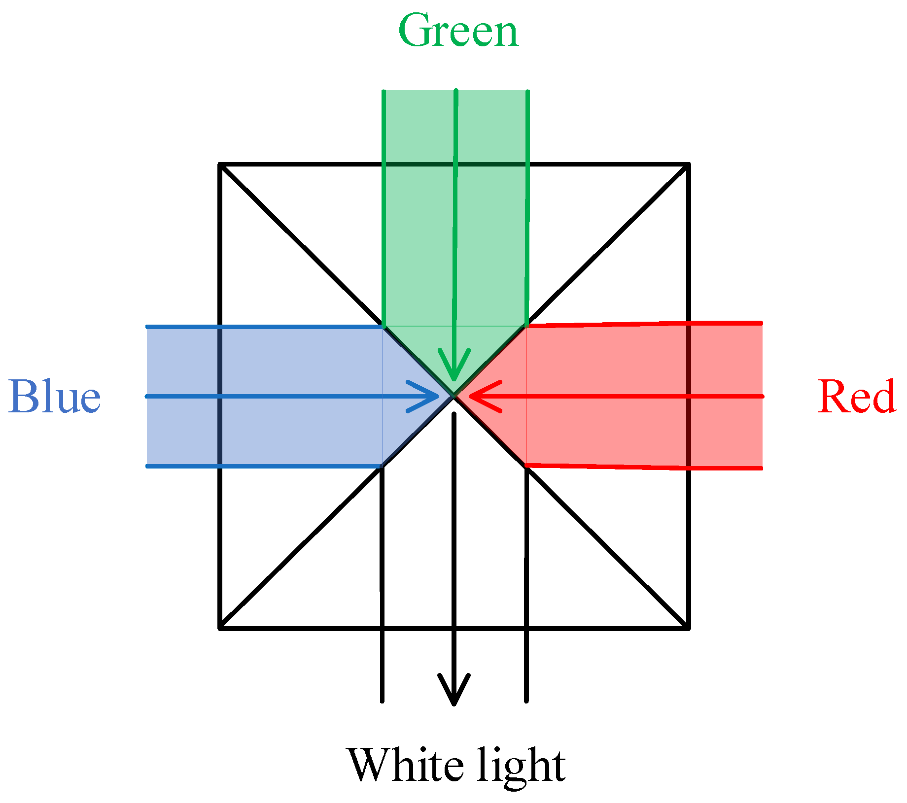
The simplified DIC system is based on a 3CDD color camera. This camera type is equipped with a refraction prism, which divides the light into R, G, and B channels and simultaneously records via three independent CCD chips. The resolution of each CCD is the same as that of the entire color camera. The captured color image of this camera is a 24-bit bitmap, which consists of three 8-bit bitmaps from different channels. The main advantage this camera type offers is that almost no color aliasing exists among the three channels; thus, it can be used for three-perspective DIC measurements. Another important advantage of this system is that it does not require a triggering device for simultaneous acquisition, as the images of the three channels are acquired simultaneously using the 3CCD camera. The 3CCD color camera used in this work is an HW-F202 with 1624 × 1236 resolution, provided by Hitachi in Beijing, China. Figure 1 shows the camera’s spectrum. If the illumination is based on the spectrum range in this figure, then no color aliasing will occur. Figure 2 presents the schematic of the cross dichroic prism, which is a combination of four triangular prisms that combine the three color beams R, G, and B to form the color image. Hence, images of different viewing angles can pass through the cross dichroic prism from three different directions and transmit into the camera lens from the same direction.
Figure 3 shows the optical arrangement of the proposed measurement system. M1 and M2 are planar mirrors.
In theory, white light illumination can be used for this system as long as the cross dichroic prism has the right bandwidth. In this work, as the camera had different reflective sensitivity responses for various light spectrums, three LEDs corresponding to the camera spectrum were used for illumination to obtain the images under similar brightness. Spectral sensitivity of the color camera showed that the sensitivity of the red channel was lower than those of the green and blue channels, thus requiring the use of a brighter red light source. The red LED we used in the experiment was adjustable in brightness. A cross dichroic prism was fixed in front of the lens and 3CCD camera, and its filter bandwidth was designed similarly to the color bands in Figure 1. The cross dichroic prism used in this system can be seen as a combination of two planar mirrors and three bandpass filters, theoretically ensuring that no distortion will be introduced. As this system was equivalent to three cameras installed at different angles, its calibration and image correlation can refer to the ordinary multi-camera DIC system. Chen’s solution is suitable for the proposed system [21].
3. Experiments and Results
Three different types of experiments were performed to verify the feasibility of the proposed system in various applications. First, a morphology test was conducted to measure the shape of a specimen with a curved surface. Second, rigid body displacement measurement was performed, whereby in-plane and out-of-plane displacement was conducted using a piezoelectric drive micro displacement platform and a flat plate. Finally, a tensile experiment was conducted to verify the accuracy of strain measurement. The standard 3D-DIC algorithm can be utilized directly to perform the evaluation, and the Istra4D provided by Dantec Dynamics was used for the evaluation because of its good performance in multi-camera calibration and DIC calculations.
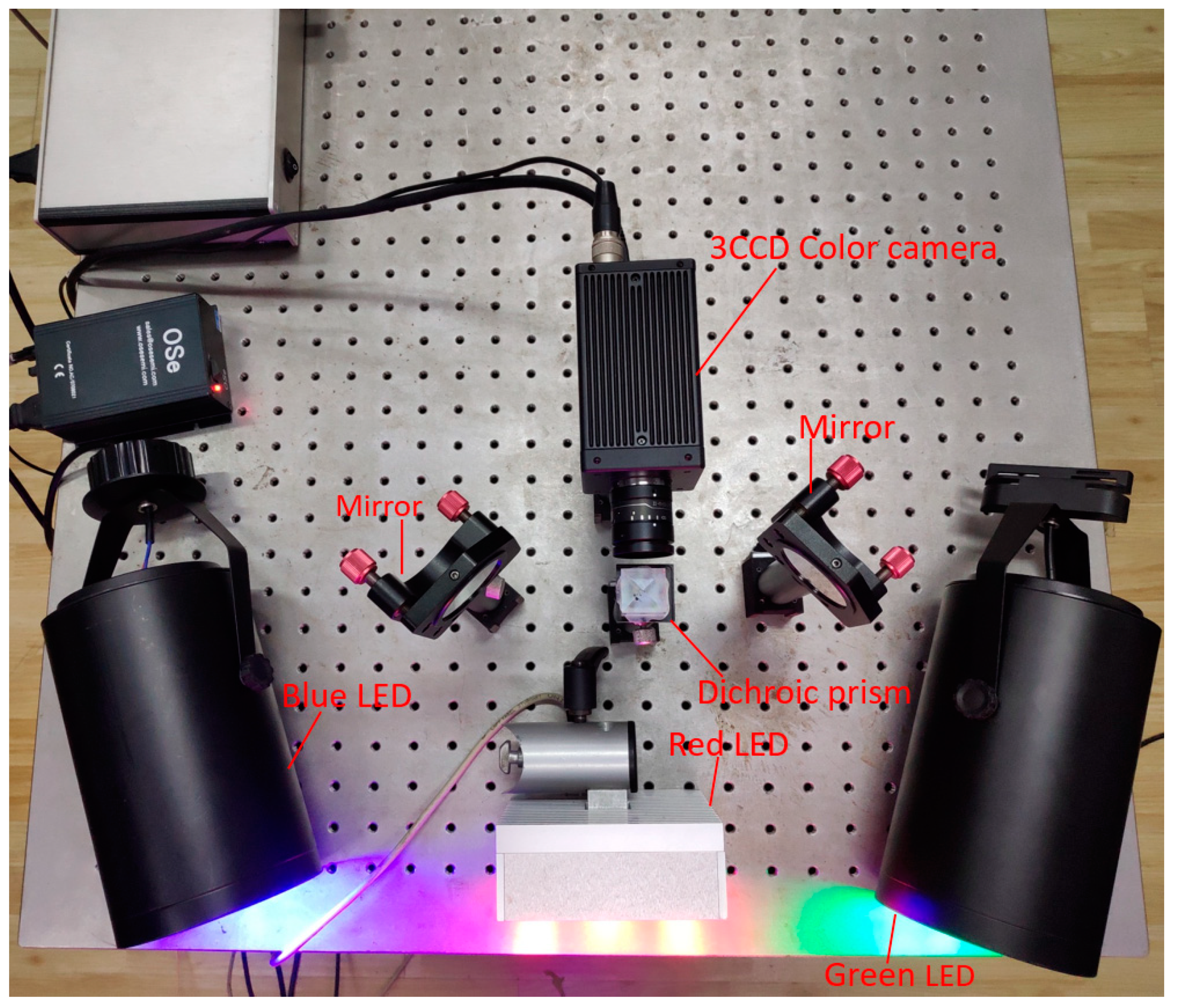
Figure 4 shows the experimental system presented in this study. In this system, the optical path of the red light is shorter than those of the blue and green lights; thus, the three channels may not be simultaneously focused. The aperture of the lens should be adjusted to small to make all channel images as clear as possible. The focal length of the lens used in the experiments was 35 mm. Adjusting the location and angle of the mirror can change the relative angle between the images of different channels. The cross dichroic prism was fixed at 8 mm in front of the camera lens. Careful adjustment was required to ensure the high quality of images of the three channels and similarity of brightness and size of the specimen being measured in the three images.
Figure 5 shows that an 8 × 8 chessboard was used to calibrate the system. The size of the small square of the calibration board was 11 mm × 11 mm. The three circles on the calibration board were used to mark the direction. Eight 24-bit images of the calibration board in different positions and directions were captured, and each 24-bit color image was converted into three 8-bit grayscale images by the R, B, and G channels. The R, B, and G channels data of the 24-bit color image were converted into three grayscale images, respectively; every image can be seen as captured by a virtual camera. The intrinsic and extrinsic parameters of the three virtual cameras can be calculated by Zhang’s calibration algorithm. The reprojection errors are shown in Figure 6.
3.1. Rigid Body Displacement Experiment
One of 3D-DIC’s major advantages is its robustness and high precision in spatial displacement measurements. In-plane and out-of-plane rigid-body movement tests were performed to validate the feasibility and accuracy of the proposed system in displacement measurement. A 100 mm × 100 mm flat plate with speckles sprayed on the surface was fixed on a piezoelectric-drive micro-displacement platform provided by Winner Optics with a resolution of 13 nm. The flat plate was displaced from 0 mm to 0.2 mm in 0.02 mm intervals in the in-plane (X) and out-of-plane (Z) directions. After setting up the experiment system, illumination intensity was adjusted to ensure similar brightness of the gray image from each channel.
While calibrating this experiment, the Z direction of the established coordinate system was parallel to the Z direction of the displacement platform. A subset size of 31 × 31 pixels and a grid step of 5 pixels were adopted in the correlation calculation. The displacement results was expressed by the average displacement of 5 × 5 subsets at the image center. Figure 7 shows the measured displacements and errors in the X and Z directions. As ensuring that the X and Z directions of the movement were exactly the same with the directions of the selected calculation coordinate was difficult, the synthesis values of X and Z directions displacements were selected to be the measured value, which were approximately coincident with the real values. Errors from the measurement were less than 0.005 mm; standard deviations of the X and Z direction synthetic displacement were 0.0025 and 0.0033 mm, respectively. Results show that the proposed system has high accuracy in displacement measurement. The displacement error map of the final step in the X displacement test is shown in Figure 8.
3.2. Morphology Measurement Experiment
The dual-camera DIC system can be used to measure regular morphology. However, for objects with complex surfaces, good results are difficult to obtain due to field of view limitations. Similarly, for big objects, the field of view of the two cameras cannot completely cover the area to be measured. The presented system involves three perspectives, and the left and right views can be adjusted independently to satisfy the requirements of complex topography measurements or of big objects, thus enabling it to achieve better results than the two-perspective DIC. The specimen used for this test was a flat aluminum plate with a cylindrical bulge in the center, and the presented system was used to measure the surface profile of the specimen. The results of three-perspective DIC calculation were compared with those of two perspectives. The left and right parts of Figure 9 show the results of DIC calculation using three and two perspectives, and the middle green channel was not included in the calculation of two perspectives. Similar parameters were used in both calculations. Figure 9 illustrates that the morphology result under three perspectives is better than that under two perspectives. Clear defects exist at the boundary between the cylindrical protrusion and plane in the morphological cloud map calculated by two channels. The reason is that the boundary line has a large error in the DIC calculations, whereas the middle channel can provide redundant information to eliminate errors. In our previous work, the DIC calculation of three fields of view had considerable advantages in measuring complex morphologies compared with two fields of view. In the calculation of double views, remarkable concave and convex regions cannot be obtained accurately through correlation calculation, whereas the three-perspective system can obtain complete information. The system proposed in this study also has this advantage. The statistical error maps in Figure 10 show that the topographical errors calculated from the three perspectives (left) are considerably smaller than the results of the two-perspective calculations (right), which represents the uncertainty of the 3D coordinates of each point.
3.3. Tensile Test for Strain Measurement
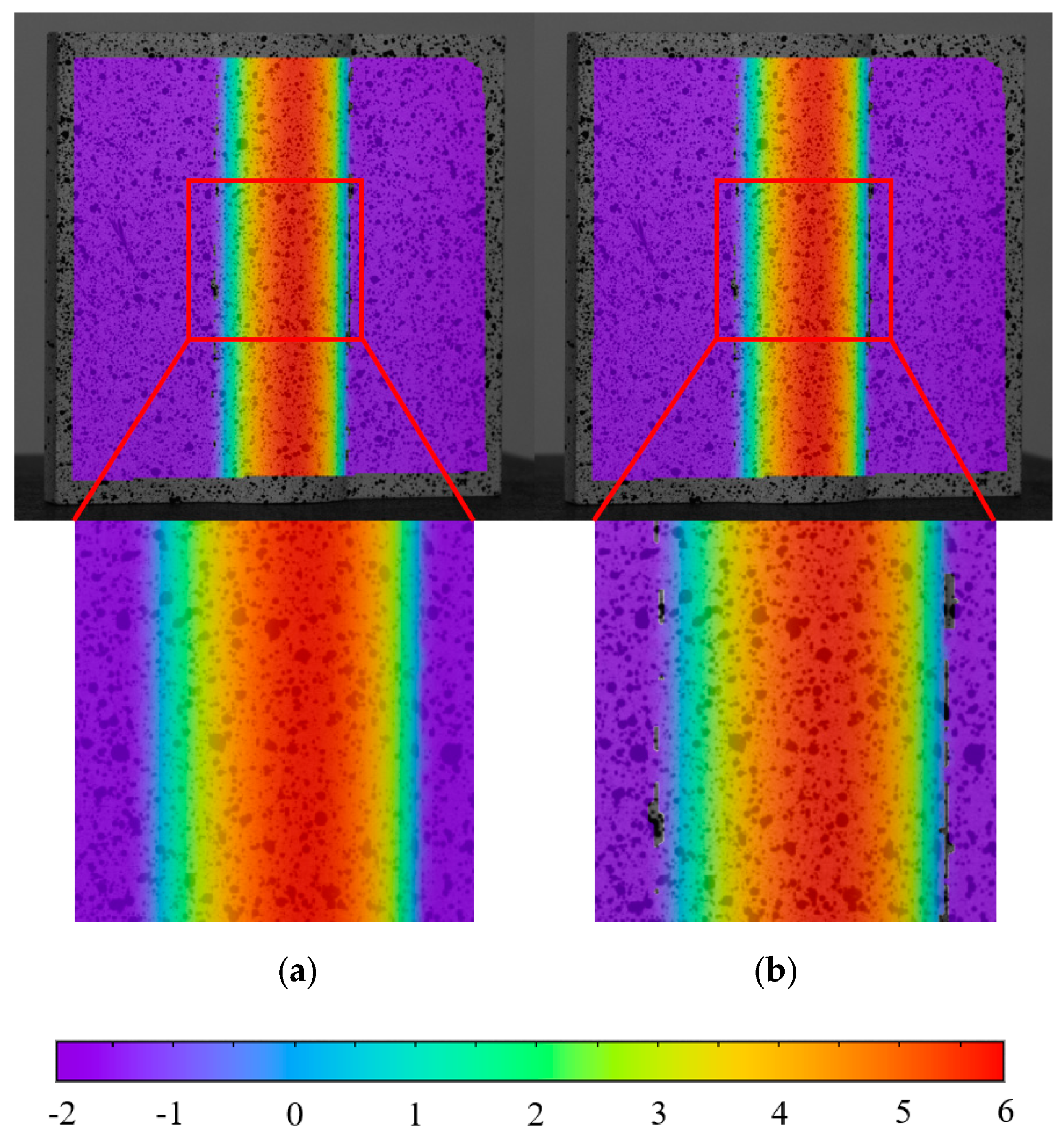
DIC strain measurement is currently the most important noncontact strain measurement method. The system presented in this study is also applicable to strain measurement. A tensile test was performed to verify the capability of the proposed system for strain measurement along with a commercial 3D-DIC system, as shown in Figure 11. A steel sheet was stretched until fracture occurred. Stretching speed is set to 2 mm/min. The proposed single camera and commercial 3D-DIC systems (Q-400 provided by Dantec Dynamics) were used to obtain the images and calculate the strain. The two systems were triggered by the same trigger source for image acquisition, and the acquisition frequency is 1 frame/s. Figure 12 shows the strain cloud before fracture, as calculated by the two systems. The left and right parts were obtained by the proposed system and the Q-400, respectively. Figure 13 displays the engineering strain curves measured by the two systems. The strain data represented by the curves are the mean values of the strain on the short straight line in Figure 12. Figure 13 presents two strain curves that are consistent. The curve calculated by the proposed system is smooth because the DIC calculation under three perspectives has the advantage of error reduction.
4. Conclusions
In this study, a novel 3D-DIC system based on a single 3CCD color camera and a cross dichroic prism is proposed. Images from three different perspectives were captured using a 3CCD camera through the cross dichroic prism and two planar mirrors, and those images were used to perform DIC calculations. Three different types of experiments were performed to verify the feasibility and accuracy of the proposed system. Results showed that this multi-perspective pseudo-vision system performed well in all three experiments.
This system has the advantages of using a single color camera and not requiring any synchronous triggering device to ensure synchronous image acquisition, resulting in a compact structure. In comparison with the existing CCD segmentation single camera 3D-DIC system, the proposed system adopts a 3CCD color camera to record images from different perspectives by using R, G, and B channels. As a result, each view can occupy an entire CCD without reducing the spatial resolution, and the need for an additional lens distortion calibration process is eliminated. In addition, this system has one additional view compared with the conventional dual-camera DIC system. Thus, the calculation results are more accurate due to the three perspectives of area coverage. This system requires only one cross dichroic prism and two planar mirrors compared with our previous system of two prisms, three mirrors, and three bandpass filters.
The proposed system still has shortcomings in some respects. The cross dichroic prism should be carefully selected to match the three channels of the color camera. Otherwise, images of the different channels will be aliased. The proposed system also requires high monochromaticity of each channel of the cross dichroic prism. The illumination brightness of the proposed system must be adjustable to maintain the similarity of the image brightness of each channel. Additionally, the optical path requires a stable environment, which limits its scope of application.
Author Contributions
X.D. prepared the whole manuscript, including writing the original draft, explaining techniques/technologies, and analyzing experimental results based on the instructions of L.Y and Y.W. J.L. provided the initial idea of this paper. The other co-authors provided some specific information and helped in writing and editing the original draft.
Funding
This work was partially supported by the National Key Research and Development Program of China (Grant number: 2016YFF0101803) and the National Natural Science Foundation of China (Grant number: 11672045).
Acknowledgments
The authors would like to express their sincere thanks to Siyuan Bao from Hefei University of Technology for his very important job for the experiments in this article.
Conflicts of Interest
The authors declare no conflict of interest.
References
- Yamaguchi, I. Speckle displacement and deformation in the diffraction and image fields for small object deformation. Opt. Acta 1981, 28, 1359–1376. [Google Scholar] [CrossRef]
- Peters, W.H.; Ranson, W.F. Digital imaging techniques in experimental stress analysis. Opt Eng. 1982, 21, 427–431. [Google Scholar] [CrossRef]
- Shao, X.; Dai, X.; Chen, Z.; He, X. Real-time 3D digital image correlation method and its application in human pulse monitoring. Appl. Opt. 2016, 55, 696–704. [Google Scholar] [CrossRef] [PubMed]
- Sutton, M.A.; Ke, X.; Lessner, S.M.; Goldbach, M.; Yost, M.; Zao, F.; Schreier, H.W. Strain field measurements on mouse carotid arteries using microscopic three-dimensional digital image correlation. J. Biomed. Mater. Res. Part A 2008, 84, 178–190. [Google Scholar] [CrossRef] [PubMed]
- Dai, X.; Yun, H.; Pu, Q. Measuring thickness change of transparent plate by electronic speckle pattern interferometry and digital image correlation. Opt. Commun. 2010, 283, 3481–3486. [Google Scholar] [CrossRef]
- Pan, B.; Qian, K.; Xie, H.; Asundi, A. Two-dimensional digital image correlation for in-plane displacement and strain measurement: A review. Meas. Sci. Technol. 2009, 20, 062001. [Google Scholar] [CrossRef]
- Chu, T.C.; Ranson, W.F.; Sutton, M.A. Applications of digital-image-correlation techniques to experimental mechanics. Exp. Mech. 1985, 25, 232–244. [Google Scholar] [CrossRef]
- Bornert, M.; Brémand, F.; Doumalin, P.; Dupre, J.-C. Addendum to: Assessment of digital image correlation measurement errors: Methodology and results. Exp. Mech. 2015, 49, 1. [Google Scholar]
- Xiao, Z. Three-dimensional digital image correlation system for deformation measurement in experimental mechanics. Opt. Eng. 2010, 49, 103601. [Google Scholar]
- Li, J.; Xin, X.; Yang, G.; Zhang, G.; Siebert, T.; Yang, L. Whole-field thickness strain measurement using multiple camera digital image correlation system. Opt. Lasers Eng. 2017, 90, 19–25. [Google Scholar] [CrossRef]
- Pankow, M.; Justusson, B.; Waas, A.M. Three-dimensional digital image correlation technique using single high-speed camera for measuring large out-of-plane displacements at high framing rates. Appl. Opt. 2010, 49, 3418. [Google Scholar] [CrossRef] [PubMed]
- Genovese, K.; Casaletto, L.; Rayas, J.A.; Flores, V.; Martinez, A. Stereo-Digital Image Correlation (DIC) measurements with a single camera using a biprism. Opt. Lasers Eng. 2013, 51, 278–285. [Google Scholar] [CrossRef]
- Barone, S.; Paolo, N.; Alessandro, P.; Armando, V.R. 3D vibration measurements by a virtual-stereo-camera system based on a single low frame rate camera. Procedia Struct. Integr. 2018, 12, 122–129. [Google Scholar] [CrossRef]
- Pan, B.; Wang, Q. Single-camera microscopic stereo digital image correlation using a diffraction grating. Opt. Express 2013, 21, 25056–25068. [Google Scholar] [CrossRef]
- Xia, S.; Gdoutou, A.; Ravichandran, G. Diffraction assisted image correlation: A novel method for measuring three-dimensional deformation using two-dimensional digital image correlation. Exp. Mech. 2013, 53, 755–765. [Google Scholar] [CrossRef]
- Junrui, L.; Xizuo, D.; Wan, X.; Wang, Y.; Yang, G.; Yang, L. 3D digital image correlation using single color camera pseudo-stereo system. Opt. Laser Technol. 2017, 95, 1–7. [Google Scholar]
- Yu, L.; Pan, B. Color stereo-digital image correlation method using a single 3CCD color camera. Exp. Mech. 2017, 57, 649–657. [Google Scholar] [CrossRef]
- Yu, L.; Pan, B. High-speed stereo-digital image correlation using a single color high-speed camera. Appl. Opt. 2018, 57, 9257–9269. [Google Scholar] [CrossRef]
- Zhong, F.Q.; Shao, X.X.; Quan, C. 3D digital image correlation using a single 3CCD colour camera and dichroic filter. Meas. Sci. Technol. 2018, 29. [Google Scholar] [CrossRef]
- Wang, Y.; Dan, X.; Li, J.; Wu, S.; Yang, L. Multi-perspective digital image correlation method using a single color camera. Sci. China Technol. Sci. 2018, 61, 61–67. [Google Scholar] [CrossRef]
- Chen, F.; Chen, X.; Xie, X.; Feng, X.; Yang, L. Full-field 3D measurement using multi-camera digital image correlation system. Opt. Lasers Eng. 2013, 51, 1044–1052. [Google Scholar] [CrossRef]
Figure 1.
Quantum efficiency of the color camera.

Figure 2.
Schematic of the cross dichroic prism.

Figure 3.
Scheme of the improved multi-perspective 3D-DIC system.

Figure 4.
Experimental setup of the improved multi-perspective 3D-DIC system.

Figure 5.
Calibration images (including the original and channel images).

Figure 6.
The reprojection errors: (a) blue channel, (b) green channel, and (c) red channel.

Figure 7.
The displacement results: (a) X direction and (b) Z direction.

Figure 8.
X direction displacement error map (the final step).

Figure 9.
Cloud map of the measured contour/mm. (a), morphology result calculated under three perspectives; (b), morphology result calculated under two perspectives (green channel was not included).
Figure 9.
Cloud map of the measured contour/mm. (a), morphology result calculated under three perspectives; (b), morphology result calculated under two perspectives (green channel was not included).

Figure 10.
Contour statistical error map/mm. (a) contour statistical error calculated under three perspectives; (b) under two perspectives (green channel was not included).
Figure 10.
Contour statistical error map/mm. (a) contour statistical error calculated under three perspectives; (b) under two perspectives (green channel was not included).

Figure 11.
The setup for the strain test.

Figure 12.
Cloud map of strain before fracture/strain. (a) proposed system; (b) Q-400 DIC system.

Figure 13.
Engineering strain curve.

© 2019 by the authors. Licensee MDPI, Basel, Switzerland. This article is an open access article distributed under the terms and conditions of the Creative Commons Attribution (CC BY) license (http://creativecommons.org/licenses/by/4.0/).
Share and Cite
MDPI and ACS Style
Dan, X.; Li, J.; Zhao, Q.; Sun, F.; Wang, Y.; Yang, L. A Cross-Dichroic-Prism-Based Multi-Perspective Digital Image Correlation System. Appl. Sci. 2019, 9, 673. https://doi.org/10.3390/app9040673
AMA Style
Dan X, Li J, Zhao Q, Sun F, Wang Y, Yang L. A Cross-Dichroic-Prism-Based Multi-Perspective Digital Image Correlation System. Applied Sciences. 2019; 9(4):673. https://doi.org/10.3390/app9040673
Chicago/Turabian StyleDan, Xizuo, Junrui Li, Qihan Zhao, Fangyuan Sun, Yonghong Wang, and Lianxiang Yang. 2019. "A Cross-Dichroic-Prism-Based Multi-Perspective Digital Image Correlation System" Applied Sciences 9, no. 4: 673. https://doi.org/10.3390/app9040673
Note that from the first issue of 2016, this journal uses article numbers instead of page numbers. See further details here.