Biomechanical Evaluation of a New Fixation Type in 3D-Printed Periacetabular Implants using a Finite Element Simulation


1
Innovative Medical Engineering & Technology, National Cancer Center, Goyang 10408, Korea
2
Orthopaedic Oncology Clinic, Specific Organs Cancer Branch, National Cancer Center, Goyang 10408, Korea
3
Research & Development Center, Medyssey Co., Ltd, Jecheon-Si 27116, Korea
*
Author to whom correspondence should be addressed.
Appl. Sci. 2019, 9(5), 820; https://doi.org/10.3390/app9050820
Submission received: 14 January 2019
/
Revised: 12 February 2019
/
Accepted: 18 February 2019
/
Published: 26 February 2019
(This article belongs to the Special Issue Biomaterials for Bone Tissue Engineering)
Abstract
:Pelvic implants require complex geometrical shapes to reconstruct unusual areas of bone defects, as well as a high mechanical strength in order to endure high compressive loads. The electron beam melting (EBM) method is capable of directly fabricating complex metallic structures and shapes based on digital models. Fixation design is important during the 3D printing of pelvic implants, given that the fixation secures the pelvic implants to the remaining bones, while also bearing large amounts of the loads placed on the bone. In this study, a horseshoe-shaped plate fixation with a bridge component between two straight plates is designed to enhance the mechanical stability of pelvic implants. The aim of this study is to investigate the biomechanics of the horseshoe-shaped plate fixation in a 3D-printed pelvic implant using a finite element (FE) simulation. First, computed tomography (CT) scans were acquired from a patient with periacetabular bone tumors. Second, 3D FE implant models were created using the patient’s Digital Imaging and Communications in Medicine (DICOM) data. Third, a FE simulation was conducted and the stress distribution between a conventional straight-type plate model, and the horseshoe-shaped plate model was compared. In both of the models, high-stress regions were observed at the iliac fixation area. In contrast, minimal stress regions were located at the pubic ramus and ischium fixation area. The key finding of this study was that the maximal stress of the horseshoe-shaped plate model (38.6 MPa) was 21% lower than that of the straight-type plate model (48.9 MPa) in the iliac fixation area. The clinical potential for the application of the horseshoe-shaped plate fixation model to the pelvic implant has been demonstrated, although this is a pilot study.
1. Introduction
Pelvic implants require complex geometrical shapes to reconstruct unusual areas of bone defects, as well as mechanical strength to endure high compressive loads [1]. For limb salvage procedures, custom pelvic prostheses have been utilized for reconstruction after the resection of bone tumors [1,2]. Custom pelvic prostheses have been fabricated by machining a solid titanium block, and this requires intensive labor and a long fabrication time [2]. Electron-beam melting (EBM), a type of 3D printing technology, can directly fabricate complex metallic structures with excellent material properties (almost no porosity) [3] and shapes, on the basis of digital models [4]. Thus, the EBM has been utilized to fabricate orthopedic components such as knee, hip, and jaw replacements, and maxillofacial plates [5,6,7,8].
For custom pelvic implants, fixation design is important, considering that the fixation secures the pelvic implants to the remaining bones, and should bear substantial loads as well [9]. A double column plating or a single column plating combined with lag screws has been commonly utilized to fix pelvic bones. The double column plating is effective to fix the complex fractures of pelvic bones [10]. However, the double column plating requires more screws for penetration during surgery, and this often results in a serious traumatic complication [11,12] that can lead to the development of osteoarthritis [11]. The single column plating combined with lag screws was regarded as the preferred technique, as it produces minimal exposure and devascularization of the pelvis [13], with comparable stability to the double column plating [13,14]. Therefore, in pelvic implants, two or three straight column platings combined with lag screws have been conventionally utilized for fixation [15,16]. These fixation types reportedly incur high traumatic fracture risks under compressive loading conditions [16,17]. Enhancements of the mechanical stability using spinal rod connectors, which have a bridge component between two straight connectors, have been reported in spine surgery publications [18,19]. Thus far, this bridge component design has not been utilized for pelvic implant fixation. We designed a horseshoe-shaped plate fixation with a bridge component between two straight plates, in an effort to enhance the mechanical stability of pelvic implants. Several studies have evaluated the strength of a conventional straight-type plate fixation for the posterior wall or transverse acetabular fractures [20,21,22,23]. In pelvic implants, there have been no studies comparing the biomechanical stabilities of the new horseshoe-shaped plate fixation with the conventional straight-type plate fixation consisting of column plates and lag screws.
The aim of this study is to investigate the biomechanics of the horseshoe-shaped plate fixation in a 3D-printed pelvic implant, using a finite element (FE) simulation. First, computed tomography (CT) scans were acquired from a patient suffering from periacetabular bone tumors. Second, 3D FE implant models, in this case a conventional straight-type plate model and the horseshoe-shaped plate model, were created using the patient’s Digital Imaging and Communications in Medicine (DICOM) data. Third, a FE simulation was performed, and the stress distribution between the straight-type plate and the horseshoe-shaped plate models was compared.
2. Materials and Methods
2.1. Patient Information
The patient was a 53-year-old woman with a height of 157 cm, weighing 50 kg. She had a recurrent high-grade spindle cell sarcoma in the left pelvic bone and proximal femur. After a type II resection, reconstruction surgery was planned using a 3D-printed titanium periacetabular implant.
2.2. 3D-Reconstruction of the Pelvic Implant Model
Figure 1 shows the anterior view of the radiographic (Figure 1a) and 3D CT (Figure 1b) images obtained from the patient. The sarcoma resection areas were represented in red dashed circles. The patient’s pelvis model was constructed using Digital Imaging and Communications in Medicine (DICOM) data based on computerized tomography (CT) scans. The DICOM data comprise a series of slices through the patient’s left pelvis, each approximately 1.0 mm thick. A 3D model of the intact pelvis was constructed using a mirror image of the right pelvis, from a series of slices.
Figure 2 presents the 3D implant model developed from the pelvic bone model using the offset function in the software MIMICS (Version 20.0, Materialise Company, Leuven, Belgium). The pelvic bone and implant are shown in grey and light yellow, respectively. For the implant fixation, the straight-type plates (Figure 2a) and the horseshoe-shaped plates (Figure 2b) were designed. The sizes of the holes in the fixation were designed to fit cannulated screw holes (D = 3.0 mm). The final implant design was completed by smoothing the rough surfaces of the implant model using the software 3-Matic (Version 13.0, Materialise Company, Leuven, Belgium). The design was stored as a Standard Triangle Language (STL) file.
2.3. Finite Element Simulation of a Pelvic Implant Model
The FE simulation was performed using the software ANSYS (Workbench 18.0, ANSYS Inc., Canonsburg, PA, USA). Figure 3 shows the pelvic implant FE models created using the straight-type plate fixation (Figure 3a) and the horseshoe-shaped plate fixation (Figure 3b). The volume mesh was created on the implant models using the software ANSYS (Workbench 18.0, ANSYS Inc., Canonsburg, PA, USA). The straight-type plate model and horseshoe-shaped plate model consist of 215,838 and 222,488 tetrahedral elements, respectively. Here, the cortical bone, cancellous bone, straight-type plate model, and horseshoe-shaped plate model are represented in yellow, blue, purple, and orange, respectively. Table 1 summarizes the material properties of the cortical bone, cancellous bone, and titanium, chosen from previous mechanical measurements [24]. Both the cortical bone and cancellous bone were assumed to be isotropic and homogeneous. The boundary conditions were defined such that the hemi-pelvis was fixed in all directions by the pubis symphysis and femoral head, represented as the green surface laid over the FE models. The contact type between the pelvis and implant was set to “bonded”, and the contact surface between the femoral head and the acetabulum was set to “frictionless.” A distributed compressive force of 4.9 kN was applied to the iliac crest, represented by the red surface laid over the FE models, along the vertical axis of the pelvis, based on the maximal load exerted by the patient’s weight [25].
3. Results
Figure 4 presents the von Mises stress distribution of the FE models with the straight-type plate fixation and the horseshoe-shaped plate fixation. In the straight-type plate model and the horseshoe-shaped plate model, a high-stress region was observed at the iliac fixation area. In contrast, low-stress regions were located at the pubic ramus and ischium fixation areas. For the straight-type plate model, the proportions of the stress concentration in the ilium, pubic ramus, and ischium were 17.8%, 2.3%, and 0.5%, respectively. For the horseshoe-shaped plate model, the corresponding stress concentration proportions were 19.8%, 2.3%, and 0.6%. In the iliac fixation area, the maximal stress of the horseshoe-shaped plate model (38.6 MPa) was 21% lower than that of the straight-type plate model (48.9 MPa).
The horseshoe-shaped plate model was fabricated for the patient’s reconstruction surgery, using EBM with the following process parameters: beam power of 3000 W, beam scan speed of 8000 m/s, beam spot size of 0.2 mm, build rate of 55 mm3/h, and a build thickness of 50 μm, on all sides of the scanning strategy. Figure 5 shows the horseshoe-shaped plate model fabricated with medical-grade titanium (Ti-6Al-4V-ELI per ASTM 136) using a powder-based EBM 3D printer (model: ARCAM A1, Arcam AB, Mölndal, Sweden) [26].
Figure 6 presents the medical images of the pelvis area obtained from the patient after the implantation surgery. The post-operative radiograph (Figure 6a) and 3D CT (Figure 6b) images demonstrated that the pelvis showed a satisfactory implant alignment and no evidence of implant loosening. In the postoperative evaluation, the patient was allowed to walk with underarm crutches two weeks after the surgery, and her feedback was positive.
4. Discussion
The FE simulation results indicated that a high-stress concentration existed in the iliac fixation area. In contrast, a low-stress region was found at the pubis and ischium fixation area (Figure 4). This high-stress concentration at the iliac fixation area has been previously reported [27,28]. Based on this stress distribution, we could conclude that the iliac fixation area bore most of the compressive load, and thus that the region of the ilium required more stable fixation with the implant than the pubis and ischium regions after type II tumor resection.
The important finding of this study was that the bridge component in the horseshoe plate model reduced the stress concentration by as much as 21% at the iliac fixation area (Figure 4). This indicates that the bridge component dissipated a large portion of the compressive load to the surrounding bones, and thus reduced the risk of fracture at the iliac fixation area. While this is the FE simulation result from only one patient’s pelvic implant, this study suggests that the bridge component of the periacetabular implant fixation would enhance the mechanical stability after type II resection. In future work, the mechanical stability of the horseshoe-shaped plate model should be evaluated in order to determine the suitability of this model for periacetabular implants in more patients.
This study demonstrated that the horseshoe-shaped plate model exhibited a more stable fixation than the conventional straight-type plate model in the pelvic implant fixation. For the fixation of a pelvic bone fracture, previous investigators have developed various fixation systems by incorporating screws or another plate into the fixation system with a column plate [13,14,29,30]. In addition to the pelvic implant fixation, our horseshoe-shaped plate model could be beneficial to enhance the stabilities of the fixation system in the pelvic bone fracture. In future studies, we will investigate stable fixation systems for the pelvic bone fracture by comparing the biomechanical stabilities between the horseshoe-shaped plate model and other conventional fixation systems.
In this study, the porous structure was applied on the surface of the titanium implants in order to reduce the stress shielding effect. The titanium implant is much stiffer than the surrounding bones, and the stress transfer between an implant device and a bone is not homogeneous [31]. The surrounding bone is then stress shielded and experiences abnormally low levels of stress, which can lead to the resorption of the bone, and again, loosening of the implant [32]. The porous titanium material has the advantages of enhancing the bone–implant interface strength by promoting bone and soft tissue ingrowth, and of reducing the bone–implant strength mismatch [33]. In future studies, the porous design, such as pores, holes, or lattice structure, should be investigated in order to enhance the mechanical properties as well as osteointegration.
Our FE simulation approach has several limitations. First, the FE simulation model was created with a uniform thickness of the cortical bone. In an actual pelvic bone, the thickness of the cortical bone varies across the pelvic bone in order to adjust to load transfers [28]. This variable thickness of the cortical bone would affect the stress distribution in the pelvic bone and the implant. Therefore, the mechanical stability of the horseshoe-shaped plate model should be evaluated further with various cortical bone thicknesses via FE simulations. Second, in the FE model, the contact type between the pelvis and implant was set to “bonded”, and the effects of the screws on the stress distribution in the pelvis bone were not considered. In future research, the stress concentration at the screw holes should be investigated with the horseshoe-shaped plate model. Third, the FE simulation was performed while only considering compressive loading conditions. We assumed that the compressive load of the patient’s weight was the most influential loading condition in the pelvis area. However, pelvic bones normally experience complex mechanical loading conditions [34]. More in-depth investigations should be performed while considering complex loading conditions in order to validate the stress distribution results in this study. Fourth, we undertook an FE simulation using a simplified FE model without including ligaments. This FE model produced sufficient results for a stress distribution comparison between the straight-type plate model and the horseshoe-shaped plate model. However, the stress distribution obtained from this FE model may not fully represent the actual loading conditions. Fifth, only the von Mises stress results were analyzed to compare the stress distribution between the conventional model and the horseshoe-shaped plate model within the scope of this study. In future studies, more parameters, such as principle stresses and strains, should be investigated in order to validate the mechanical stability of the horseshoe-shaped plate model.
5. Conclusions
The horseshoe-shaped plate fixation demonstrated an enhanced mechanical stability in a 3D-printed titanium periacetabular implant. The horseshoe-shaped plate fixation model may have clinical potential and thus warrants more extensive clinical investigations.
Author Contributions
Conceptualization, D.W.P. and H.G.K.; methodology, D.W.P.; software, A.L.; validation, A.L. and D.W.P.; formal analysis, A.L. and D.W.P.; investigation, D.W.P.; resources, J.W.P. and K.M.L.; data curation, A.L. and D.W.P.; writing (original draft preparation), D.W.P.; writing (review and editing), J.W.P. and H.G.K.; visualization, D.W.P.; supervision, H.G.K.; project administration, H.G.K.
Funding
This study was supported by a grant from the Korea Health Technology R&D Project through the Korea Health Industry Development Institute (KHIDI), and was funded by the Ministry of Health and Welfare, Republic of Korea (grant number HI17C1823).
Acknowledgments
The technical support of the finite element software was provided by the Medical Device Development Center of the Daegu-Gyeongbuk Medical Innovation Foundation.
Conflicts of Interest
The authors declare no conflict of interest.
References
- Wong, K.C.; Kumta, S.M.; Geel, N.V.; Demol, J. One-step reconstruction with a 3D-printed, biomechanically evaluated custom implant after complex pelvic tumor resection. Comput. Aided. Surg. 2015, 20, 14–23. [Google Scholar] [CrossRef] [PubMed] [Green Version]
- Fan, H.; Fu, J.; Li, X.; Pei, Y.; Li, X.; Pei, G.; Guo, Z. Implantation of customized 3-D printed titanium prosthesis in limb salvage surgery: A case series and review of the literature. World J. Surg. Oncol. 2015, 13, 308. [Google Scholar] [CrossRef] [PubMed]
- Sing, S.L.; An, J.; Yeong, W.Y. Laser and electron-beam powder-bed additive manufacturing of metallic implants: A review on processes, materials and designs. J. Orthop. Res. 2015, 34, 369–385. [Google Scholar] [CrossRef] [PubMed] [Green Version]
- Rengier, F.; Mehndiratta, A.; von Tengg-Kobligk, H.; Zechmann, C.M.; Unterhinninghofen, R.; Kauczor, H.U.; Giesel, F.L. 3D printing based on imaging data: Review of medical applications. Int. J. Comput. Assist. Radiol. Surg. 2010, 5, 335–341. [Google Scholar] [CrossRef] [PubMed]
- Cronskär, M.; Bäckström, M.; Rännar, L.-E. Production of customized hip stem prostheses—A comparison between conventional machining and electron beam melting (EBM). Rapid Prototyp. J. 2013, 19, 365–372. [Google Scholar]
- Mazzoli, A.; Germani, M.; Raffaeli, R. Direct fabrication through electron beam melting technology of custom cranial implants designed in a PHANToM-based haptic environment. Mater. Des. 2009, 30, 3186–3192. [Google Scholar] [CrossRef]
- Jardini, A.L.; Larosa, M.A.; de Carvalho Zavaglia, C.A.; Bernardes, L.F.; Lamber, C.S. Customised titanium implant fabricated in additive manufacturing for craniomaxillofacial surgery. Virtual Phys. Prototyp. 2014, 9, 115–125. [Google Scholar] [CrossRef]
- Jardini, A.L.; Larosaemail, M.A.; Filho, R.M.; de Carvalho Zavaglia, C.A.; Bernardes, L.F.; Lambert, C.S.; Calderoni, D.R.; Kharmandayan, P. Cranial reconstruction: 3D biomodel and custom-built implant created using additive manufacturing. J. Craniomaxillofac. Surg. 2014, 42, 1877–1884. [Google Scholar] [CrossRef] [PubMed]
- Lei, J.; Dong, P.; Li, Z.; Zhu, F.; Wang, Z.; Cai, X. Biomechanical analysis of the fixation systems for anterior column and posterior hemi-transverse acetabular fractures. Acta Orthopaedica et Traumatologica Turcica 2017, 51, 248–253. [Google Scholar] [CrossRef] [PubMed]
- Wolf, H.; Wieland, T.; Pajenda, G.; Vecsei, V.; Mousavi, M. Minimally invasive ilioinguinal approach to the acetabulum. Injury 2007, 38, 1170–1176. [Google Scholar] [CrossRef] [PubMed]
- Russell, G.V.; Nork, S.E.; Chip, R.M.L. Perioperative complications associated with operative treatment of acetabular fractures. J. Trauma Acute Care Surg. 2001, 51, 1098–1103. [Google Scholar] [CrossRef]
- Ebraheim, N.A.; Savolaine, E.R.; Hoeflinger, M.J.; Jackson, W.T. Radiological diagnosis of screw penetration of the hip joint in acetabular fracture reconstruction. J. Orthop. Trauma 1989, 3, 196–201. [Google Scholar] [CrossRef] [PubMed]
- Sawaguchi, T.; Brown, T.D.; Rubash, H.E.; Mears, D.C. Stability of acetabular fractures after internal fixation: A cadaveric study. Acta Orthop. 1984, 55, 601–605. [Google Scholar] [CrossRef] [Green Version]
- Schopfer, A.; DiAngelo, D.; Hearn, T.; Powell, J.; Tile, M. Biomechanical comparison of methods of fixation of isolated osteotomies of the posterior acetabular column. Int. Orthop. 1994, 18, 96–101. [Google Scholar] [CrossRef] [PubMed]
- Singh, V.A.; Elbahri, H.; Shanmugam, R. Biomechanical analysis of a novel acetabulum reconstruction technique with acetabulum reconstruction cage and threaded rods after type II pelvic resections. Sarcoma 2016, 2016, 1–7. [Google Scholar] [CrossRef] [PubMed]
- Plessers, K.; Mau, H. Stress analysis of a Burch-Schneider cage in an acetabular bone defect: A case study. Reconstr. Rev. 2016, 6, 37–42. [Google Scholar] [CrossRef] [Green Version]
- Atik, F.; Ataç, M.S.; Özkan, A.; Kilinç, Y.; Arslan, M. Biomechanical analysis of titanium fixation plates and screws in mandibular angle fractures. Niger. J. Clin. Pract. 2016, 19, 386–390. [Google Scholar] [PubMed]
- Zhang, B.C.; Liu, H.B.; Kai, X.H.; Wang, Z.H.; Xu, F.; Kang, H.; Ding, R.; Luo, X.Q. Biomechanical comparison of a novel transoral atlantoaxial anchored cage with established fixation technique—A finite element analysis. BMC Musculoskelet. Disord. 2015, 16, 216. [Google Scholar] [CrossRef] [PubMed]
- Goel, V.K.; Mehta, A.; Jangra, J.; Faizan, A.; Kiapour, A.; Hoy, R.W.; Fauth, A.R. Anatomic facet replacement system (AFRS) restoration of lumbar segment mechanics to intact: A finite element study and in vitro cadaver investigation. SAS J. 2007, 1, 46–54. [Google Scholar] [CrossRef]
- Chang, J.K.; Gill, S.S.; Zura, R.D.; Krause, W.R.; Wang, G.J. Comparative strength of three methods of fixation of transverse acetabular fractures. Clin. Orthop. Relat. Res. 2001, 392, 433–441. [Google Scholar] [CrossRef]
- Shazar, N.; Brumback, R.J.; Novak, V.P.; Belkoff, S.M. Biomechanical evaluation of transverse acetabular fracture fixation. Clin. Orthop. Relat. Res. 1998, 352, 215–222. [Google Scholar] [CrossRef]
- Xin-wei, L.; Shuo-gui, X.; Chun-cai, Z.; Qing-ge, F.; Pan-feng, W. Biomechanical study of posterior wall acetabular fracture fixation using acetabular tridimensional memory alloy-fixation system. Clin. Biomech. 2010, 25, 312–317. [Google Scholar] [CrossRef] [PubMed]
- Olson, S.A.; Bay, B.K.; Chapman, M.W.; Sharkey, N.A. Biomechanical consequences of fracture and repair of the posterior wall of the acetabulum. J. Bone Joint Surg. Am. 1995, 77, 1184–1192. [Google Scholar] [CrossRef] [PubMed]
- Aziz, M.S.R.; Dessouki, O.; Samiezadeh, S.; Bougherara, H.; Schemitsch, E.H.; Zero, R. Biomechanical analysis using FEA and experiments of a standard plate method versus three cable methods for fixing acetabular fractures with simultaneous THA. Med. Eng. Phys. 2017, 46, 71–78. [Google Scholar] [CrossRef] [PubMed]
- Bergmann, G.; Graichen, F.; Rohlmann, A. Hip joint loading during walking and running, measured in two patients. J. Biomech. 1993, 26, 969–990. [Google Scholar] [CrossRef]
- Harrysson, O.L.A.; Cansizoglu, O.; Marcellin-Little, D.J.; Cormier, D.R.; West II, H.A. Direct metal fabrication of titanium implants with tailored materials and mechanical properties using electron beam melting technology. Mater. Sci. Eng. C 2008, 28, 366–373. [Google Scholar] [CrossRef]
- Shen, F.H.; Mason, J.R.; Shimer, A.L.; Arlet, V.M. Pelvic fixation for adult scoliosis. Eur. Spine J. 2013, 22 (Suppl. 2), 265–275. [Google Scholar] [CrossRef] [PubMed]
- Thompson, M.S.; Northmore-Ball, M.D.; Tanner, K.E. Effects of acetabular resurfacing component material and fixation on the strain distribution in the pelvis. Proc. Inst. Mech. Eng. 2002, 216, 237–245. [Google Scholar] [CrossRef] [PubMed]
- Wu, Y.; Cai, X.; Liu, X.; Zhang, H. Biomechanical analysis of the acetabular buttressplate: Are complex acetabular fractures in the quadrilateral area stable after treatment with anterior construct plate-1/3 tube buttress plate fixation? Clinics 2013, 68, 1028e1033. [Google Scholar] [CrossRef]
- Andersen, R.C.; O’Toole, R.V.; Nascone, J.W.; Sciadini, M.F.; Frisch, H.M.; Turen, C.W. Modified stoppa approach for acetabular fractures with anterior and posterior column displacement: Quantification of radiographic reduction and analysis of interobserver variability. J. Orthop. Trauma 2010, 24, 271e278. [Google Scholar] [CrossRef] [PubMed]
- Niinomi, M.; Nakai, M. Titanium-Based Biomaterials for Preventing Stress Shielding between Implant Devices and Bone. Int. J. Biomater. 2011, 2011, 836587. [Google Scholar] [CrossRef] [PubMed]
- Black, J. Biological Performance of Materials, Fundamentals of Biocompatibility, 3rd ed.; Marcel Dekker: New York, NY, USA, 1999. [Google Scholar]
- Thelen, S.; Barthelat, F.; Brinson, L.C. Mechanics considerations for microporous titanium as an orthopedic implant material. J. Biomed. Mater. Res. A 2004, 69A, 601–610. [Google Scholar] [CrossRef] [PubMed]
- Dalstra, M.; Huiskes, R.; van Erning, L. Development and validation of a three-dimensional finite element model of the pelvic bone. J. Biomech. Eng. 1995, 117, 272–278. [Google Scholar] [CrossRef] [PubMed]
Figure 1.
Pre-operative medical images of the pelvis area obtained from the patient: (a) plain radiograph and (b) 3D computed tomography (CT) images.
Figure 1.
Pre-operative medical images of the pelvis area obtained from the patient: (a) plain radiograph and (b) 3D computed tomography (CT) images.

Figure 2.
3D model of the periacetabular implant and femur shaft area. The implant fixation models with (a) the straight-type plates and (b) the horseshoe-shaped plates.
Figure 2.
3D model of the periacetabular implant and femur shaft area. The implant fixation models with (a) the straight-type plates and (b) the horseshoe-shaped plates.
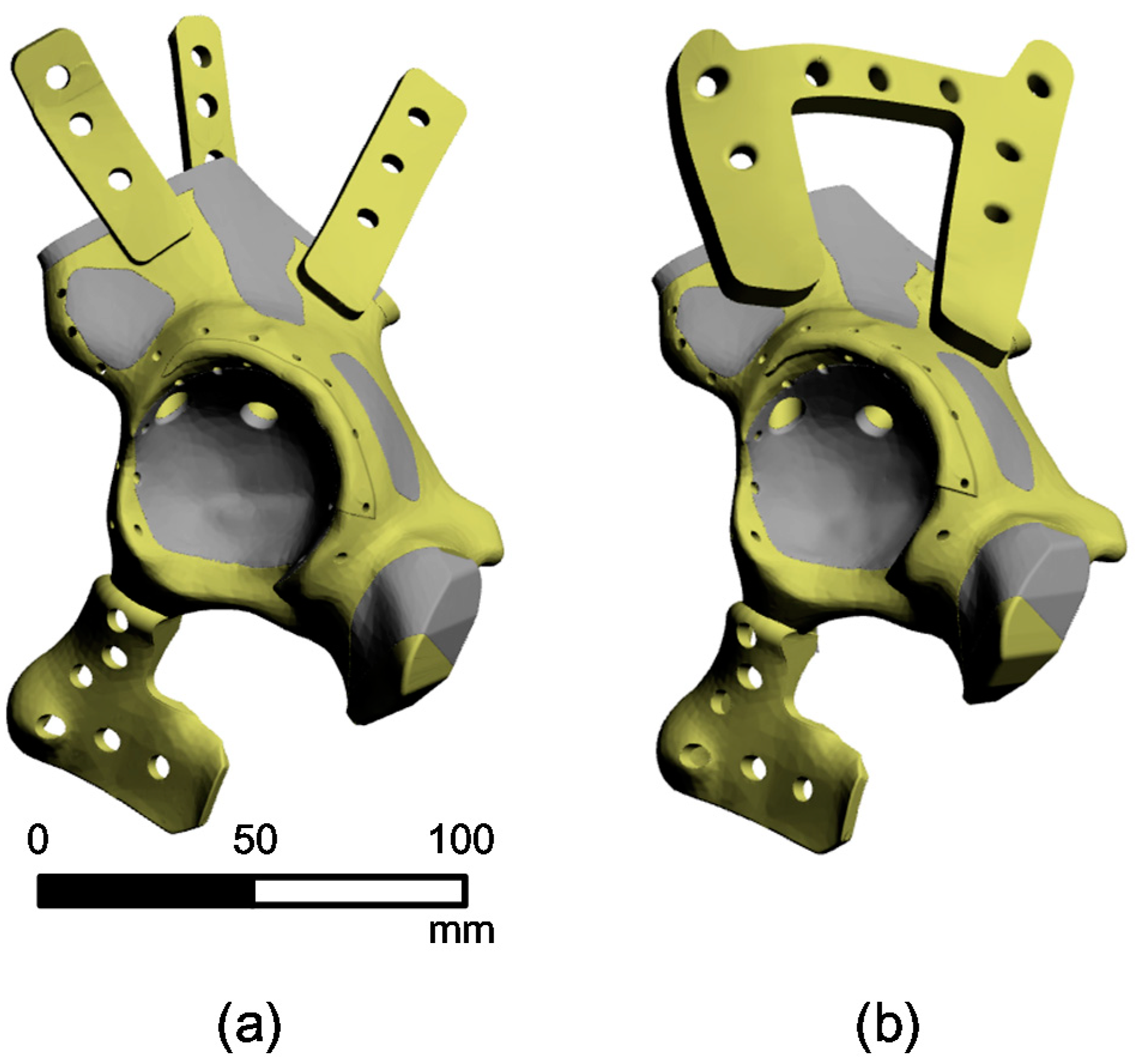
Figure 3.
Boundary conditions of finite element (FE) models with (a) the straight-type plate fixation and (b) the horseshoe-shaped plate fixation.
Figure 3.
Boundary conditions of finite element (FE) models with (a) the straight-type plate fixation and (b) the horseshoe-shaped plate fixation.

Figure 4.
The von Mises stress distribution of the finite element (FE) models with (a) the straight-type plate fixation and (b) the horseshoe-shaped plate fixation.
Figure 4.
The von Mises stress distribution of the finite element (FE) models with (a) the straight-type plate fixation and (b) the horseshoe-shaped plate fixation.
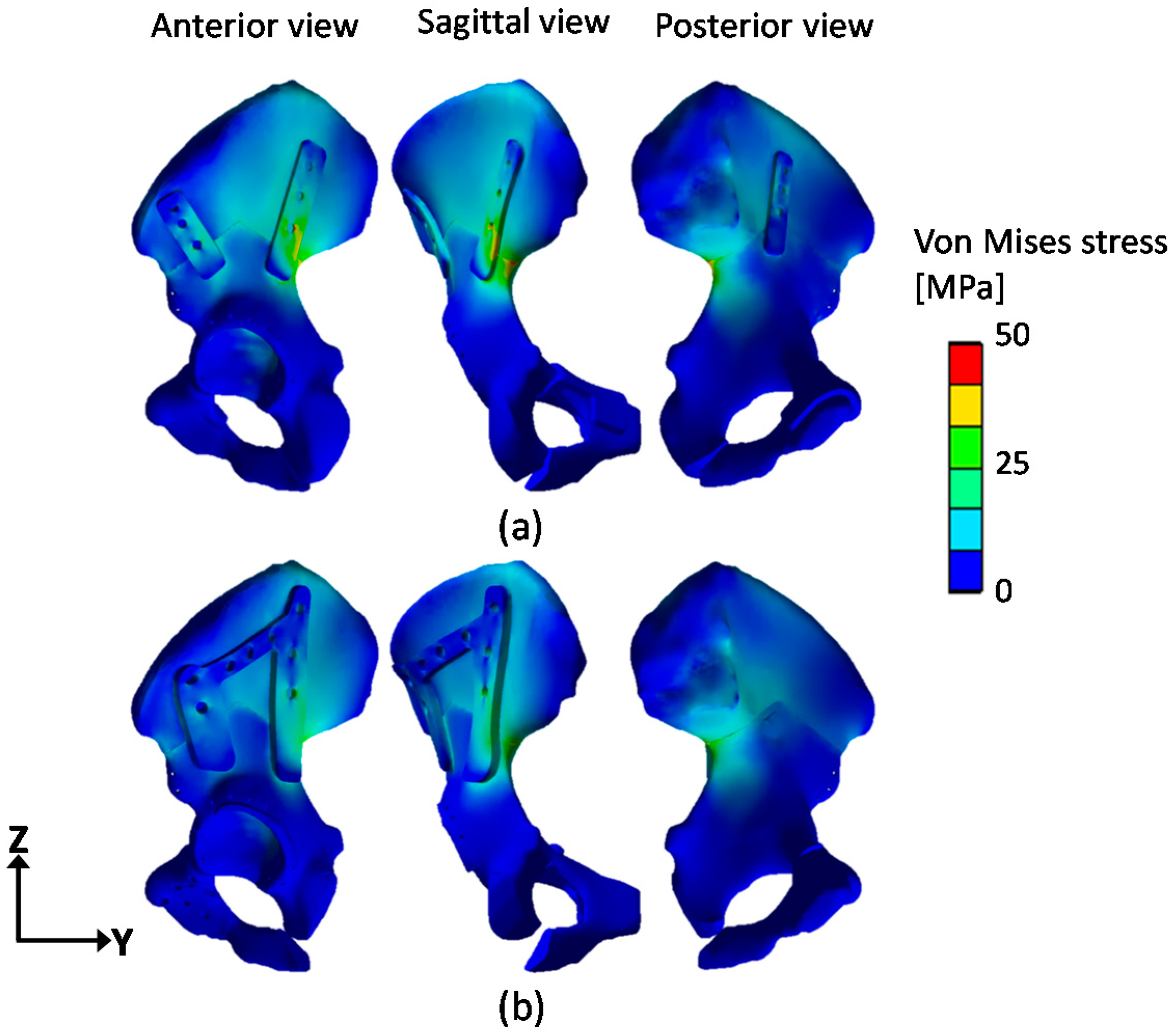
Figure 5.
3D-printed titanium periacetabular implant with the horseshoe-shaped plates.
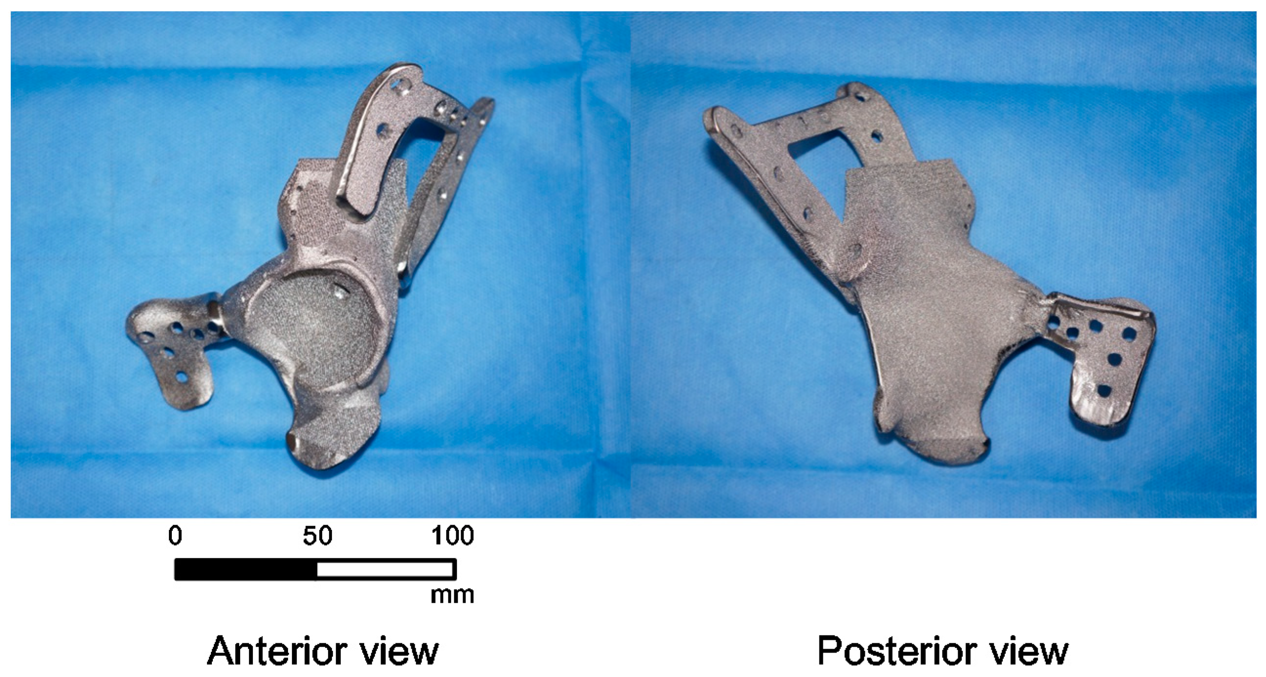
Figure 6.
Post-operative medical images of the pelvis area obtained from a patient: (a) plain radiograph and (b) 3D CT images.
Figure 6.
Post-operative medical images of the pelvis area obtained from a patient: (a) plain radiograph and (b) 3D CT images.


Table 1.
Material properties used for the finite element simulation.
| Material | Density (g/cm3) | Young’s Modulus (MPa) | Poisson’s Ratio (v) | Tensile Strength (MPa) | Compressive Strength (MPa) |
|---|---|---|---|---|---|
| Cortical bone | 1.64 | 16,700 | 0.26 | 106 | 157 |
| Cancellous bone | 0.16 | 155 | 0.30 | 6 | 6 |
| Ti-6Al-4V | 4.62 | 96,000 | 0.36 | 1070 | 1070 |
© 2019 by the authors. Licensee MDPI, Basel, Switzerland. This article is an open access article distributed under the terms and conditions of the Creative Commons Attribution (CC BY) license (http://creativecommons.org/licenses/by/4.0/).
Share and Cite
MDPI and ACS Style
Park, D.W.; Lim, A.; Park, J.W.; Lim, K.M.; Kang, H.G. Biomechanical Evaluation of a New Fixation Type in 3D-Printed Periacetabular Implants using a Finite Element Simulation. Appl. Sci. 2019, 9, 820. https://doi.org/10.3390/app9050820
AMA Style
Park DW, Lim A, Park JW, Lim KM, Kang HG. Biomechanical Evaluation of a New Fixation Type in 3D-Printed Periacetabular Implants using a Finite Element Simulation. Applied Sciences. 2019; 9(5):820. https://doi.org/10.3390/app9050820
Chicago/Turabian StylePark, Dae Woo, Aekyeong Lim, Jong Woong Park, Kwon Mook Lim, and Hyun Guy Kang. 2019. "Biomechanical Evaluation of a New Fixation Type in 3D-Printed Periacetabular Implants using a Finite Element Simulation" Applied Sciences 9, no. 5: 820. https://doi.org/10.3390/app9050820
Note that from the first issue of 2016, this journal uses article numbers instead of page numbers. See further details here.