Implementation of Shape Memory Alloy Sponge as Energy Dissipating Material on Pounding Tuned Mass Damper: An Experimental Investigation

 and
and
Abstract
:1. Introduction
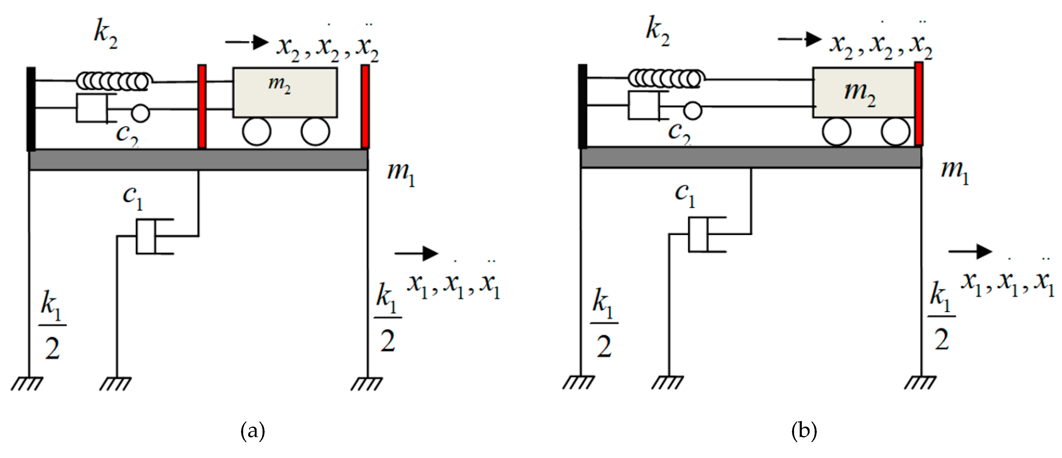
2. Pounding Tuned Mass Damper (PTMD) and Energy Dissipating Material
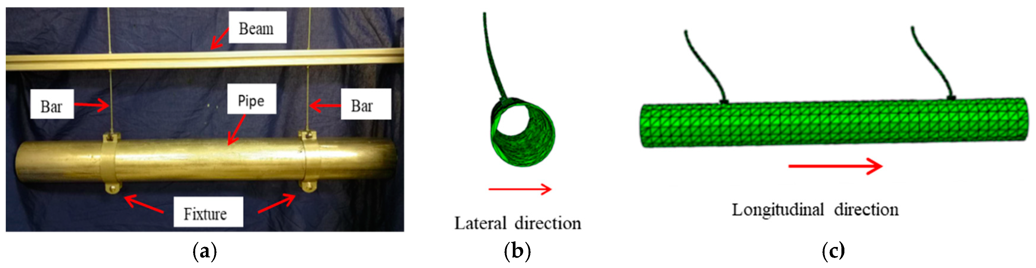
3. Modal Analysis of a Suspended Piping System
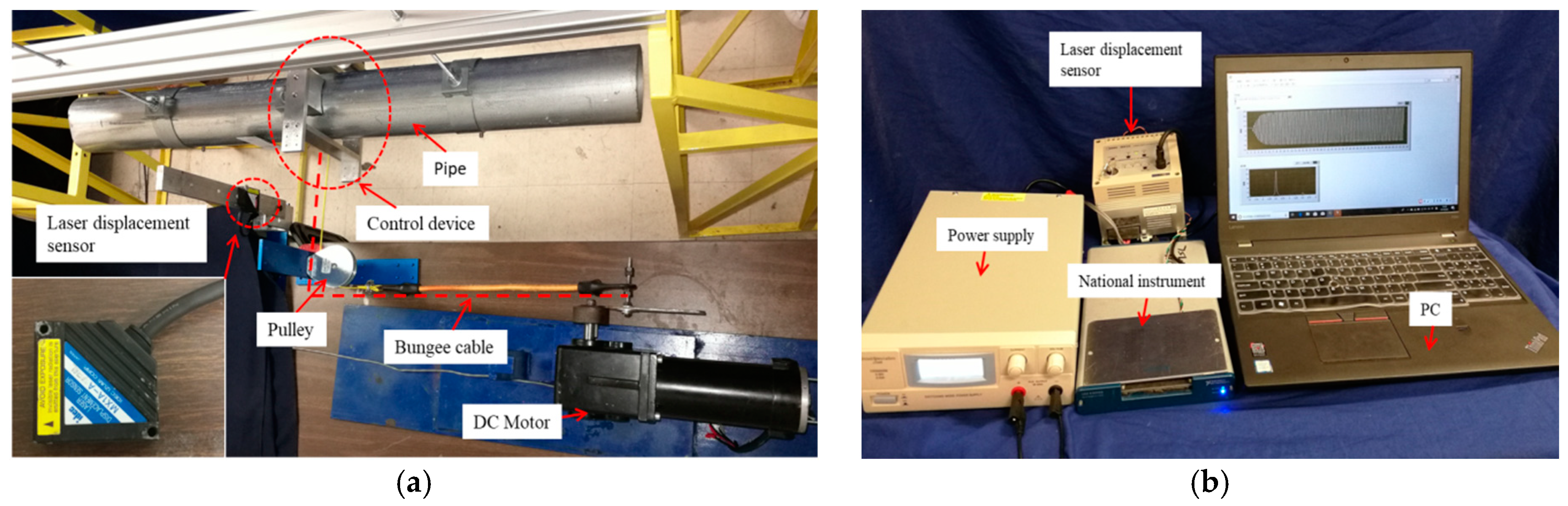
4. Experimental Setup
5. Results and Discussion
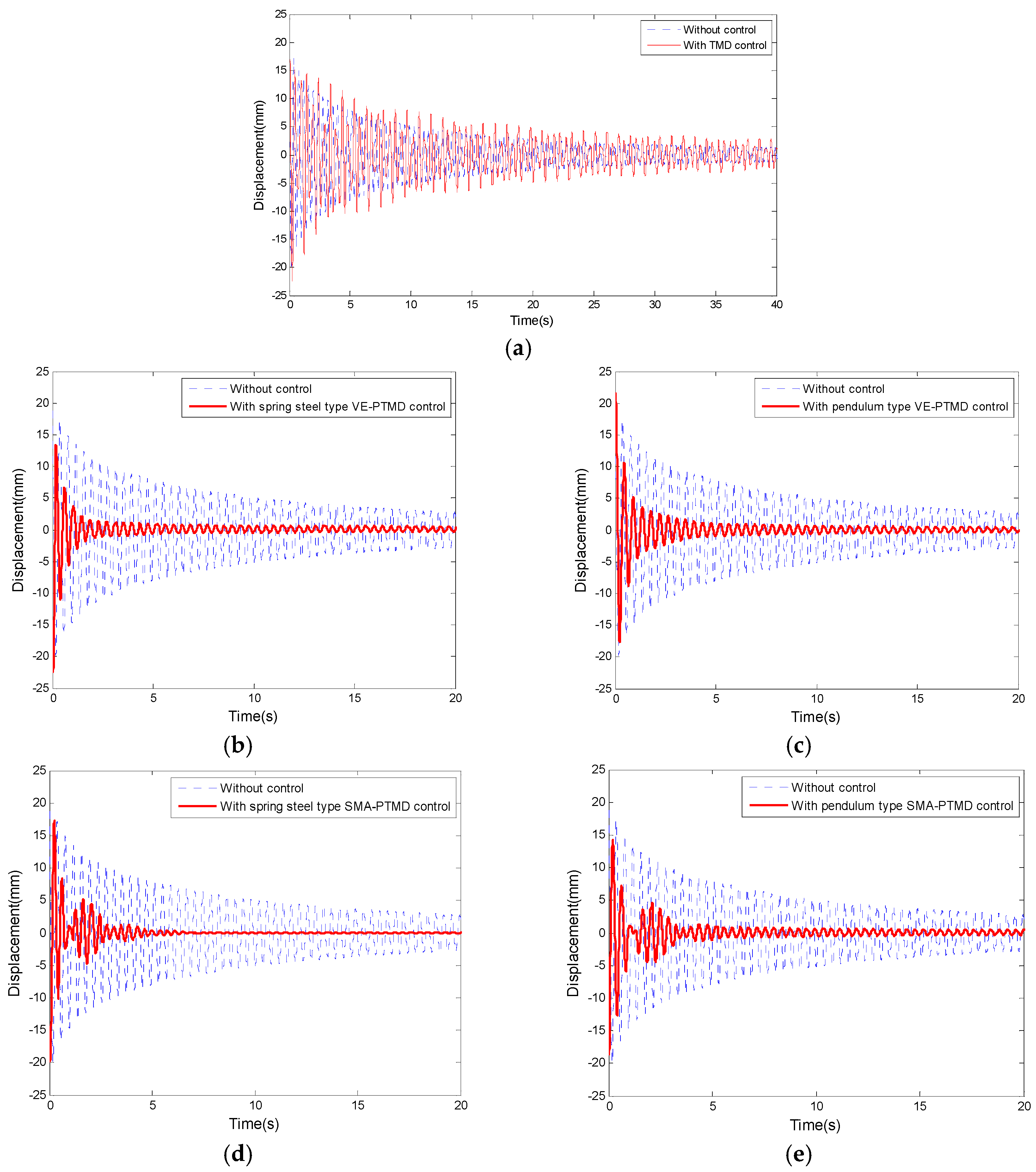
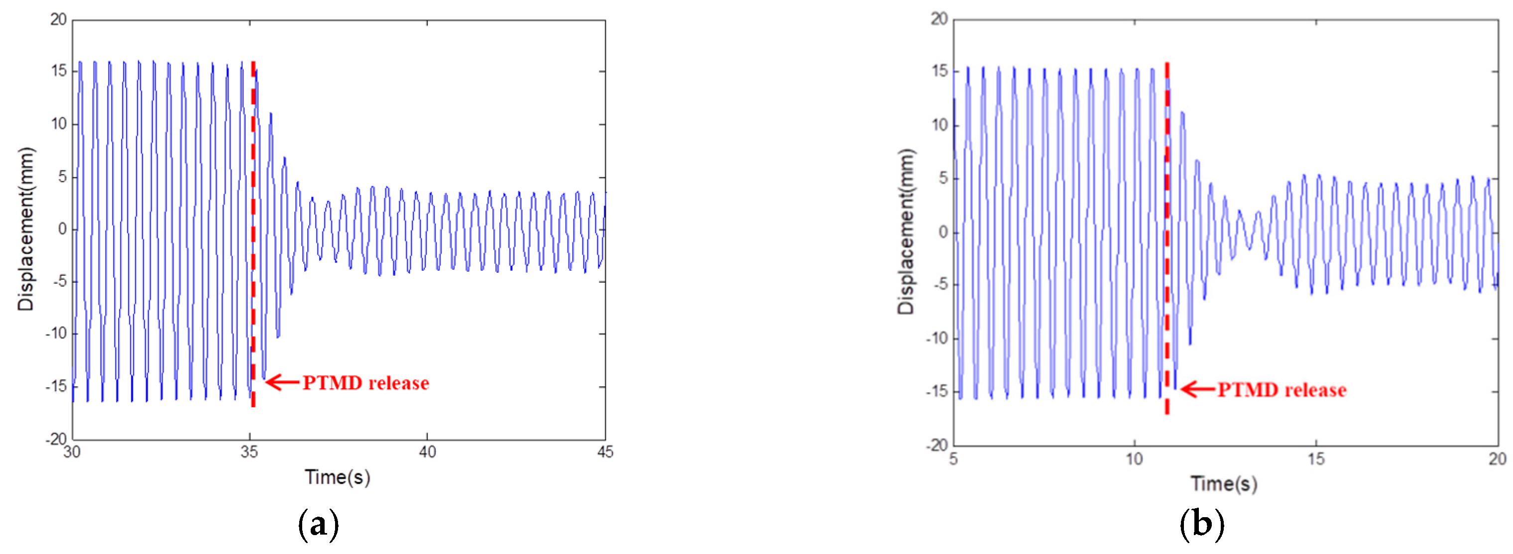
5.1. Suppression of Free Vibration
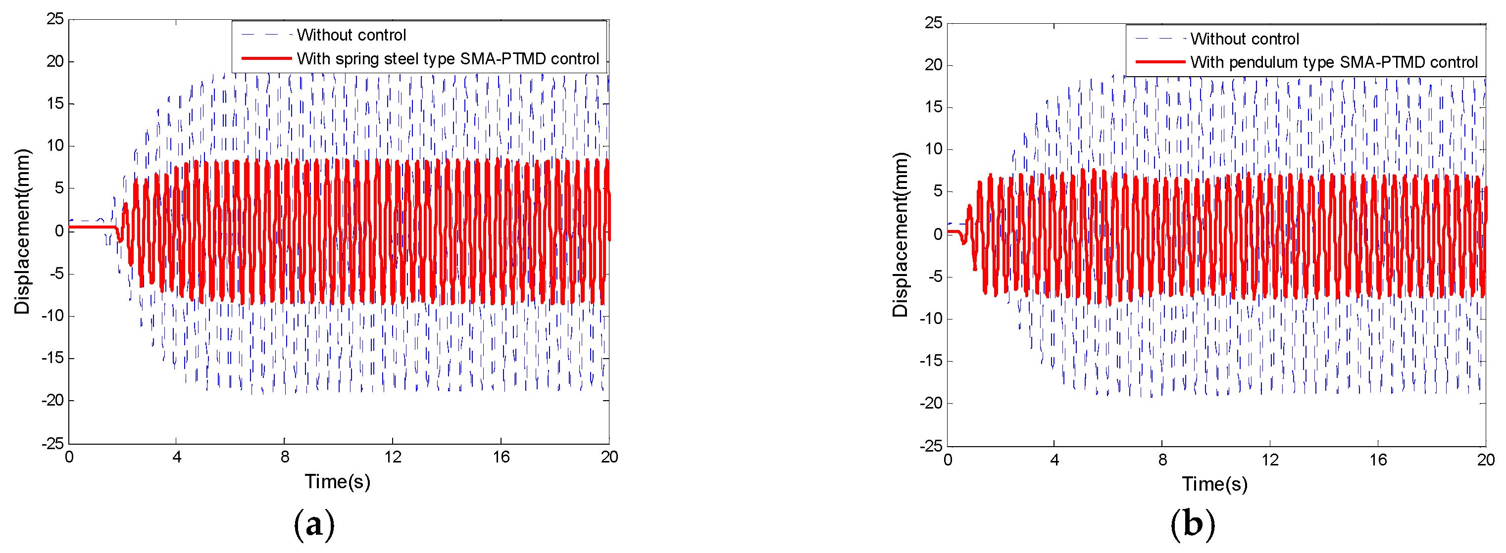
5.2. Suppression of Forced Vibration
6. Conclusions
Author Contributions
Funding
Conflicts of Interest
References
- Hall, J.F.; Holmes, W.T.; Somers, P. Northridge Earthquake; Preliminary reconnaissance report; EERI: Oakland, CA, USA, 1994. [Google Scholar]
- Gates, W.E.; McGavin, G. Lessons learned from the 1994 Northridge earthquake on the vulnerability of nonstructural systems. In Proceedings of the Seminar on Seismic Design, Retrofit, and Performance of Nonstructural Components, San Francisco, CA, USA, 22–23 January 1998. [Google Scholar]
- Whittaker, A.S.; Soong, T.T. An overview of nonstructural components research at three US Earthquake Engineering Research Centers. In Proceedings of the ATC Seminar on Seismic Design, Performance, and Retrofit of Nonstructural Components in Critical Facilities, Newport Beach, CA, USA, 23–24 October 2003. [Google Scholar]
- Taghavi, S.; Miranda, E. Response Assessment of Nonstructural Building Elements; Pacific Earthquake Engineering Research Center: Berkeley, CA, USA, 2003. [Google Scholar]
- Chock, G. Preliminary Observations on the Hawaii Earthquakes of October 15, 2006; EERI special earthquake report; EERI: Oakland, CA, USA, 2006. [Google Scholar]
- Miranda, E.; Mosqueda, G.; Retamales, R.; Pekcan, G. Performance of nonstructural components during the 27 February 2010 Chile earthquake. Earthq. Spectra 2012, 28 (Suppl. 1), S453–S471. [Google Scholar] [CrossRef]
- Ayres, J.M.; Phillips, R.J. Water damage in hospitals resulting from the Northridge earthquake. Ashrae Trans. 1998, 104, 1286. [Google Scholar]
- Goltz, J. The Northridge, California Earthquake of January 17, 1994; General reconnaissance report; National Center for Earthquake Engineering Research: Buffalo, NY, USA, 1994. [Google Scholar]
- Fleming, R.P. Analysis of Fire Sprinkler Systems Performance in the Northridge Earthquake; (No. Grant/Contract Reports (NISTGCR)-98-736); National Institute of Standards and Technology: Gaithersburg, MD, USA, 1998.
- Hardy, G.S.; Smith, P.D.; Tang, Y.K. Piping seismic adequacy criteria recommendations based on performance during earthquakes. Nucl. Eng. Des. 1988, 107, 155–160. [Google Scholar] [CrossRef]
- Zaghi, A.E.; Maragakis, E.M.; Itani, A.; Goodwin, E. Experimental and analytical studies of hospital piping assemblies subjected to seismic loading. Earthq. Spectra 2012, 28, 367–384. [Google Scholar] [CrossRef]
- Tian, Y.; Filiatrault, A.; Mosqueda, G. Seismic response of pressurized fire sprinkler piping systems II: Numerical study. J. Earthq. Eng. 2015, 19, 674–699. [Google Scholar] [CrossRef]
- Norris, M.A.; Ptak, K.R.; Zamora, B.A.; Hart, J.D. Implementation of tuned vibration absorbers for above ground pipeline vibration control. In Proceedings of the 2000 3rd International Pipeline Conference, Calgary, AB, Canada, 1–5 October 2000; p. V001T02A005. [Google Scholar]
- Kumar, P.; Jangid, R.S.; Reddy, G.R. Comparative performance of passive devices for piping system under seismic excitation. Nucl. Eng. Des. 2016, 298, 121–134. [Google Scholar] [CrossRef]
- Namita, Y.; Shigeta, M.; Yoshinaga, T.; Gotoh, N.; Kawahata, J. The application of elastoplastic support devices for a piping system: Device test and vibration test of piping system and simulation analysis. JSME Int. J. Ser. 3 Vib. Control Eng. Eng. Ind. 1991, 34, 42–48. [Google Scholar] [CrossRef]
- Nims, D. Large-Scale Experimental Studies of Two Alternate Support Systems for the Seismic Restraint of Piping. Ph.D. Thesis, University of California at Berkeley, Berkeley, CA, USA, 1991. [Google Scholar]
- Suzuki, K.; Watanabe, T.; Mitsumori, T.; Shimizu, N.; Kobayashi, H.; Ogawa, N. Experimental Study on Seismic Responses of Piping Systems with Friction—Part 1: Large-Scale Shaking Table Vibration Test. J. Press. Vessel Technol. 1995, 117, 245–249. [Google Scholar] [CrossRef]
- Bakre, S.V.; Jangid, R.S.; Reddy, G.R. Response of piping system on friction support to bi-directional excitation. Nucl. Eng. Des. 2007, 237, 124–136. [Google Scholar] [CrossRef]
- Suarez, E.; Roldán, A.; Gallego, A.; Benavent-Climent, A. Entropy analysis for damage quantification of hysteretic dampers used as seismic protection of buildings. Appl. Sci. 2017, 7, 628. [Google Scholar] [CrossRef]
- Kang, J.D.; Mori, Y. Evaluation of a Simplified Method to Estimate the Peak Inter-Story Drift Ratio of Steel Frames with Hysteretic Dampers. Appl. Sci. 2017, 7, 449. [Google Scholar] [CrossRef]
- Fu, W.; Zhang, C.; Sun, L.; Askari, M.; Samali, B.; Chung, K.L.; Sharafi, P. Experimental investigation of a base isolation system incorporating MR dampers with the high-order single step control algorithm. Appl. Sci. 2017, 7, 344. [Google Scholar] [CrossRef]
- Gastaldi, C.; Fantetti, A.; Berruti, T. Forced response prediction of turbine blades with flexible dampers: The impact of engineering modelling choices. Appl. Sci. 2018, 8, 34. [Google Scholar] [CrossRef]
- Huo, L.; Song, G.; Nagarajaiah, S.; Li, H. Semi-active vibration suppression of a space truss structure using a fault tolerant controller. J. Vib. Control 2012, 18, 1436–1453. [Google Scholar] [CrossRef]
- Demetriou, D.; Nikitas, N.; Tsavdaridis, K.D. Semi active tuned mass dampers of buildings: A simple control option. Am. J. Eng. Appl. Sci. 2015, 8, 620–632. [Google Scholar] [CrossRef]
- Li, L.; Song, G.; Ou, J. A genetic algorithm-based two-phase design for optimal placement of semi-active dampers for nonlinear benchmark structure. J. Vib. Control 2010, 16, 1379–1392. [Google Scholar] [CrossRef]
- Kim, B.; Yoon, J.Y. Enhanced Adaptive Filtering Algorithm Based on Sliding Mode Control for Active Vibration Rejection of Smart Beam Structures. Appl. Sci. 2017, 7, 750. [Google Scholar] [CrossRef]
- Lin, C.Y.; Jheng, H.W. Active vibration suppression of a motor-driven piezoelectric smart structure using adaptive fuzzy sliding mode control and repetitive control. Appl. Sci. 2017, 7, 240. [Google Scholar] [CrossRef]
- Gu, H.; Song, G. Active vibration suppression of a flexible beam with piezoceramic patches using robust model reference control. Smart Mater. Struct. 2007, 16, 1453. [Google Scholar] [CrossRef]
- Kim, H.; Adeli, H. Hybrid control of smart structures using a novel wavelet-based algorithm. Comput. Aided Civ. Infrastruct. Eng. 2005, 20, 7–22. [Google Scholar] [CrossRef]
- Ozbulut, O.E.; Hurlebaus, S. Application of an SMA-based hybrid control device to 20-story nonlinear benchmark building. Earthq. Eng. Struct. Dyn. 2012, 41, 1831–1843. [Google Scholar] [CrossRef]
- Demetriou, D.; Nikitas, N. A novel hybrid semi-active mass damper configuration for structural applications. Appl. Sci. 2016, 6, 397. [Google Scholar] [CrossRef]
- Palacios-Quiñonero, F.; Rubió-Massegú, J.; Rossell, J.M.; Karimi, H.R. Integrated design of hybrid interstory-interbuilding multi-actuation schemes for vibration control of adjacent buildings under seismic excitations. Appl. Sci. 2017, 7, 323. [Google Scholar] [CrossRef]
- Lu, Z.; Chen, X.; Zhang, D.; Dai, K. Experimental and analytical study on the performance of particle tuned mass dampers under seismic excitation. Earthq. Eng. Struct. Dyn. 2017, 46, 697–714. [Google Scholar] [CrossRef]
- Chen, J.; Lu, G.; Li, Y.; Wang, T.; Wang, W.; Song, G. Experimental study on robustness of an eddy current-tuned mass damper. Appl. Sci. 2017, 7, 895. [Google Scholar] [CrossRef]
- Kaloop, M.R.; Hu, J.W.; Bigdeli, Y. Identification of the response of a controlled building structure subjected to seismic load by using nonlinear system models. Appl. Sci. 2016, 6, 301. [Google Scholar] [CrossRef]
- Song, G.; Li, L.; Singla, M.; Mo, Y.L. Pounding Tune Mass Damper with Viscoelastic Material. U.S. Patent 9 2016,500,247, 22 November 2016. [Google Scholar]
- Wang, W.; Hua, X.; Wang, X.; Chen, Z.; Song, G. Numerical modeling and experimental study on a novel pounding tuned mass damper. J. Vib. Control 2018, 24, 4023–4036. [Google Scholar] [CrossRef]
- Jiang, J.; Zhang, P.; Patil, D.; Li, H.N.; Song, G. Experimental studies on the effectiveness and robustness of a pounding tuned mass damper for vibration suppression of a submerged cylindrical pipe. Struct. Control Health Monit. 2017, 24, e2027. [Google Scholar] [CrossRef]
- Xue, Q.; Zhang, J.; He, J.; Zhang, C. Control performance and robustness of pounding tuned mass damper for vibration reduction in SDOF structure. Shock Vib. 2016, 2016, 8021690. [Google Scholar] [CrossRef]
- Zhang, P.; Song, G.; Li, H.N.; Lin, Y.X. Seismic control of power transmission tower using pounding TMD. J. Eng. Mech. 2012, 139, 1395–1406. [Google Scholar] [CrossRef]
- Lin, W.; Wang, Q.; Li, J.; Chen, S.; Qi, A. Shaking table test of pounding tuned mass damper (PTMD) on a frame structure under earthquake excitation. Comput. Concr. 2017, 20, 545–553. [Google Scholar]
- Li, H.-N.; Zhang, P.; Song, G.; Patil, D.; Mo, Y. Robustness study of the pounding tuned mass damper for vibration control of subsea jumpers. Smart Mater. Struct. 2015, 24, 095001. [Google Scholar] [CrossRef]
- Song, G.; Zhang, P.; Li, L.Y.; Singla, M.; Patil, D.; Li, H.N.; Mo, Y.L. Vibration control of a pipeline structure using pounding tuned mass damper. J. Eng. Mech. 2016, 142, 04016031. [Google Scholar] [CrossRef]
- Lin, W.; Song, G.; Chen, S. PTMD control on a benchmark TV tower under earthquake and wind load excitations. Appl. Sci. 2017, 7, 425. [Google Scholar] [CrossRef]
- Tan, J.; Ho, M.; Chun, S.; Zhang, P.; Jiang, J. Experimental Study on Vibration Control of Suspended Piping System by Single-Sided Pounding Tuned Mass Damper. Appl. Sci. 2019, 9, 285. [Google Scholar] [CrossRef]
- Ren, W.; Li, H.; Song, G. Phenomenological modeling of the cyclic behavior of superelastic shape memory alloys. Smart Mater. Struct. 2007, 16, 1083. [Google Scholar] [CrossRef]
- Sun, M.; Chang, M.; Wang, Z.; Li, H.; Sun, X. Experimental and Simulation Study of Low-Velocity Impact on Glass Fiber Composite Laminates with Reinforcing Shape Memory Alloys at Different Layer Positions. Appl. Sci. 2018, 8, 2405. [Google Scholar] [CrossRef]
- Hong, K.; Lee, S.; Han, S.; Yeon, Y. Evaluation of Fe-Based Shape Memory Alloy (Fe-SMA) as Strengthening Material for Reinforced Concrete Structures. Appl. Sci. 2018, 8, 730. [Google Scholar] [CrossRef]
- Seo, J.; Kim, Y.C.; Hu, J.W. Pilot study for investigating the cyclic behavior of slit damper systems with recentering shape memory alloy (SMA) bending bars used for seismic restrainers. Appl. Sci. 2015, 5, 187–208. [Google Scholar] [CrossRef]
- Qian, H.; Li, H.; Song, G. Experimental investigations of building structure with a superelastic shape memory alloy friction damper subject to seismic loads. Smart Mater. Struct. 2016, 25, 125026. [Google Scholar] [CrossRef]
- Xu, M.B.; Song, G. Adaptive control of vibration wave propagation in cylindrical shells using SMA wall joint. J. Sound Vib. 2004, 278, 307–326. [Google Scholar] [CrossRef]
- Rustighi, E.; Brennan, M.J.; Mace, B.R. Real-time control of a shape memory alloy adaptive tuned vibration absorber. Smart Mater. Struct. 2005, 14, 1184–1195. [Google Scholar] [CrossRef]
- Rustighi, E.; Brennan, M.J.; Mace, B.R. A shape memory alloy adaptive tuned vibration absorber: Design and implementation. Smart Mater. Struct. 2004, 14, 19–28. [Google Scholar] [CrossRef]
- Santos, F.A.D.; Nunes, J. Toward an adaptive vibration absorber using shape-memory alloys, for civil engineering applications. J. Intell. Mater. Syst. Struct. 2018, 29, 729–740. [Google Scholar] [CrossRef]
- Williams, K.A.; Chiu, G.T.C.; Bernhard, R.J. Nonlinear control of a shape memory alloy adaptive tuned vibration absorber. J. Sound Vib. 2005, 288, 1131–1155. [Google Scholar] [CrossRef]
- Williams, K.; Chiu, G.; Bernhard, R. Adaptive-passive absorbers using shape-memory alloys. J. Sound Vib. 2002, 249, 835–848. [Google Scholar] [CrossRef]
- Berardengo, M.; Cigada, A.; Guanziroli, F.; Manzoni, S. Modelling and control of an adaptive tuned mass damper based on shape memory alloys and eddy currents. J. Sound Vib. 2015, 349, 18–38. [Google Scholar] [CrossRef]
- Savi, M.A.; De Paula, A.S.; Lagoudas, D.C. Numerical investigation of an adaptive vibration absorber using shape memory alloys. J. Intell. Mater. Syst. Struct. 2011, 22, 67–80. [Google Scholar] [CrossRef]
- Aguiar, R.A.; Savi, M.A.; Pacheco, P.M. Experimental investigation of vibration reduction using shape memory alloys. J. Intell. Mater. Syst. Struct. 2013, 24, 247–261. [Google Scholar] [CrossRef]
- Berardengo, M.; Della Porta, G.E.; Manzoni, S.; Vanali, M. A multi-modal adaptive tuned mass damper based on shape memory alloys. J. Intell. Mater. Syst. Struct. 2019, 30, 536–555. [Google Scholar] [CrossRef]
- Senthilkumar, P.; Umapathy, M. Use of load generated by a shape memory alloy for its position control with a neural network estimator. J. Vib. Control 2014, 20, 1707–1717. [Google Scholar] [CrossRef]
- Wang, W.; Wang, X.; Hua, X.; Song, G.; Chen, Z. Vibration control of vortex-induced vibrations of a bridge deck by a single-side pounding tuned mass damper. Eng. Struct. 2018, 173, 61–75. [Google Scholar] [CrossRef]
- Feng, Q.; Fan, L.; Huo, L.; Song, G. Vibration Reduction of an Existing Glass Window through a Viscoelastic Material-Based Retrofit. Appl. Sci. 2018, 8, 1061. [Google Scholar] [CrossRef]
- Wang, W.; Hua, X.; Wang, X.; Chen, Z.; Song, G. Advanced Impact Force Model for Low-Speed Pounding between Viscoelastic Materials and Steel. J. Eng. Mech. 2017, 143, 04017139. [Google Scholar] [CrossRef]
- Bonfitto, A.; Tonoli, A.; Amati, N. Viscoelastic Dampers for Rotors: Modeling and Validation at Component and System Level. Appl. Sci. 2017, 7, 1181. [Google Scholar] [CrossRef]
- Zhang, P.; Li, L.; Patil, D.; Singla, M.; Li, H.N.; Mo, Y.L.; Song, G. Parametric study of pounding tuned mass damper for subsea jumpers. Smart Mater. Struct. 2015, 25, 015028. [Google Scholar] [CrossRef]
- Wang, W.; Hua, X.; Wang, X.; Chen, Z.; Song, G. Optimum design of a novel pounding tuned mass damper under harmonic excitation. Smart Mater. Struct. 2017, 26, 055024. [Google Scholar] [CrossRef]
- Song, G.; Ma, N.; Li, H.N. Applications of shape memory alloys in civil structures. Eng. Struct. 2006, 28, 1266–1274. [Google Scholar] [CrossRef]
- Sawaguchi, T.; Maruyama, T.; Otsuka, H.; Kushibe, A.; Inoue, Y.; Tsuzaki, K. Design concept and applications of Fe–Mn–Si-based alloys—From shape-memory to seismic response control. Mater. Trans. 2016, 57, 283–293. [Google Scholar] [CrossRef]
- Jani, J.M.; Leary, M.; Subic, A.; Gibson, M.A. A review of shape memory alloy research, applications and opportunities. Mater. Des. (1980–2015) 2014, 56, 1078–1113. [Google Scholar] [CrossRef]
- Menna, C.; Auricchio, F.; Asprone, D. Applications of shape memory alloys in structural engineering. In Shape Memory Alloy Engineering; Heinemann: Butterworth, Malaysia, 2015; pp. 369–403. [Google Scholar]
- Ren 2015, W.; Li, H.; Song, G. A one-dimensional strain-rate-dependent constitutive model for superelastic shape memory alloys. Smart Mater. Struct. 2007, 16, 191. [Google Scholar] [CrossRef]
- Saadat, S.; Salichs, J.; Noori, M.; Hou, Z.; Davoodi, H.; Bar-On, I.; Suzuki, Y.; Masuda, A. An overview of vibration and seismic applications of NiTi shape memory alloy. Smart Mater. Struct. 2002, 11, 218. [Google Scholar] [CrossRef]
- Li, H.N.; Qian, H.; Song, G.B.; Gao, D.W. Type of shape memory alloy damper: Design, experiment and numerical simulation. J. Vib. Eng. 2008, 21, 179–184. [Google Scholar]
- Li, H.; Liu, Z.Q.; Ou, J.P. Experimental study of a simple reinforced concrete beam temporarily strengthened by SMA wires followed by permanent strengthening with CFRP plates. Eng. Struct. 2008, 30, 716–723. [Google Scholar] [CrossRef]
- Dolce, M.; Cardone, D.; Marnetto, R. Implementation and testing of passive control devices based on shape memory alloys. Earthq. Eng. Struct. Dyn. 2000, 29, 945–968. [Google Scholar] [CrossRef]
- Zhou, P.; Liu, M.; Li, H.; Song, G. Experimental investigations on seismic control of cable-stayed bridges using shape memory alloy self-centering dampers. Struct. Control Health Monit. 2018, 25, e2180. [Google Scholar] [CrossRef]
- Li, H.; Liu, M.; Ou, J. Vibration mitigation of a stay cable with one shape memory alloy damper. Struct. Control Health Monit. 2004, 11, 21–36. [Google Scholar] [CrossRef]
- Wilde, K.; Gardoni, P.; Fujino, Y. Base isolation system with shape memory alloy device for elevated highway bridges. Eng. Struct. 2000, 22, 222–229. [Google Scholar] [CrossRef]
- Dolce, M.; Cardone, D.; Marnetto, R. SMA recentering devices for seismic isolation of civil structures. In Smart Structures and Materials 2001: Smart Systems for Bridges, Structures, and Highways; International Society for Optics and Photonics: Newport Beach, CA, USA, 2001; Volume 4330, pp. 238–250. [Google Scholar]
- Khan, M.M.; Lagoudas, D.C. Modeling of shape memory alloy pseudoelastic spring elements using Preisach model for passive vibration isolation. In Smart Structures and Materials 2002: Modeling, Signal Processing, and Control; International Society for Optics and Photonics: San Diego, CA, USA, 2002; Volume 4693, pp. 336–348. [Google Scholar]
- Mayes, J.; Lagoudas, D.; Henderson, B. An experimental investigation of shape memory alloy springs for passive vibration isolation. In Proceedings of the AIAA Space 2001 Conference and Exposition, Albuquerque, NM, USA, 28–30 August 2001; p. 4569. [Google Scholar]
- Corbi, O. Shape memory alloys and their application in structural oscillations attenuation. Simul. Model. Pract. Theory 2003, 11, 387–402. [Google Scholar] [CrossRef]
- Miller, D.J.; Fahnestock, L.A.; Eatherton, M.R. Development and experimental validation of a nickel–titanium shape memory alloy self-centering buckling-restrained brace. Eng. Struct. 2012, 40, 288–298. [Google Scholar] [CrossRef]
- Huang, B.; Zhang, H.; Wang, H.; Song, G. Passive base isolation with superelastic nitinol SMA helical springs. Smart Mater. Struct. 2014, 23, 065009. [Google Scholar] [CrossRef]
- Asgarian, B.; Moradi, S. Seismic response of steel braced frames with shape memory alloy braces. J. Constr. Steel Res. 2011, 67, 65–74. [Google Scholar] [CrossRef]
- DDS Simulia, ABAQUS Unified FEA Software. Available online: www.3ds.com (accessed on 1 March 2019).
- Tributsch, A.; Adam, C. Evaluation and analytical approximation of tuned mass damper performance in an earthquake environment. Smart Struct. Syst. 2012, 10, 155–179. [Google Scholar] [CrossRef]
- Anajafi, H.; Medina, R.A. Comparison of the seismic performance of a partial mass isolation technique with conventional TMD and base-isolation systems under broad-band and narrow-band excitations. Eng. Struct. 2018, 158, 110–123. [Google Scholar] [CrossRef]
- Den Hartog, J.P. Mechanical Vibrations; Courier Corporation: North Chelmsford, MA, USA, 1985. [Google Scholar]


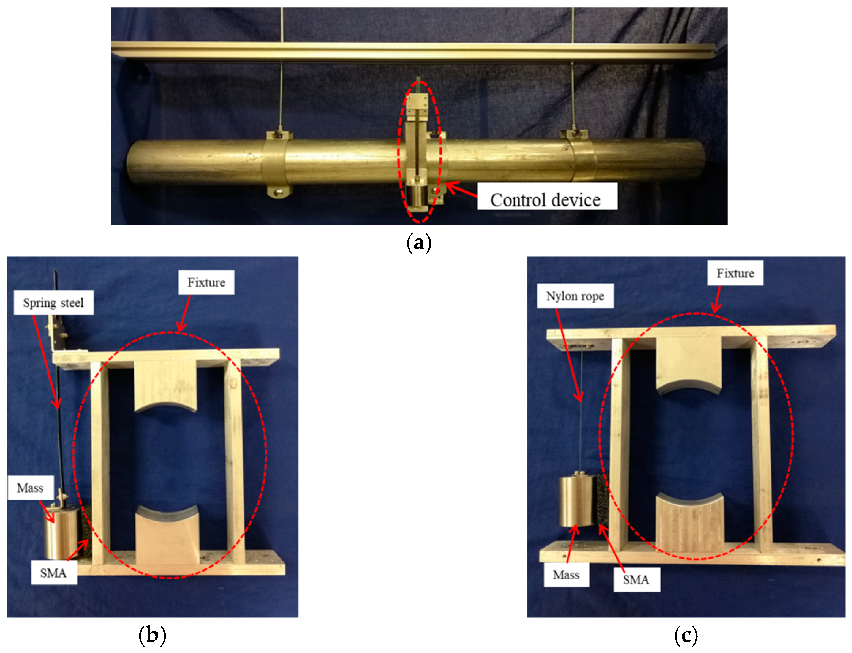
| PTMD (Spring steel type) | Frequency of the spring steel–mass system | 1.28 Hz | |
| Component | Description | Value | |
| Spring steel | Material | Spring steel | |
| Dimensions (mm) | 170 × 6.5 × 0.4 | ||
| PTMD (Pendulum type) | Frequency of the pendulum–mass system | 1.28 Hz | |
| Component | Description | Value | |
| Nylon rope | Material | Nylon | |
| Length (mm) | 128 | ||
| Mass for PTMDs | Material | Steel | |
| Weight (kg) | 0.403 | ||
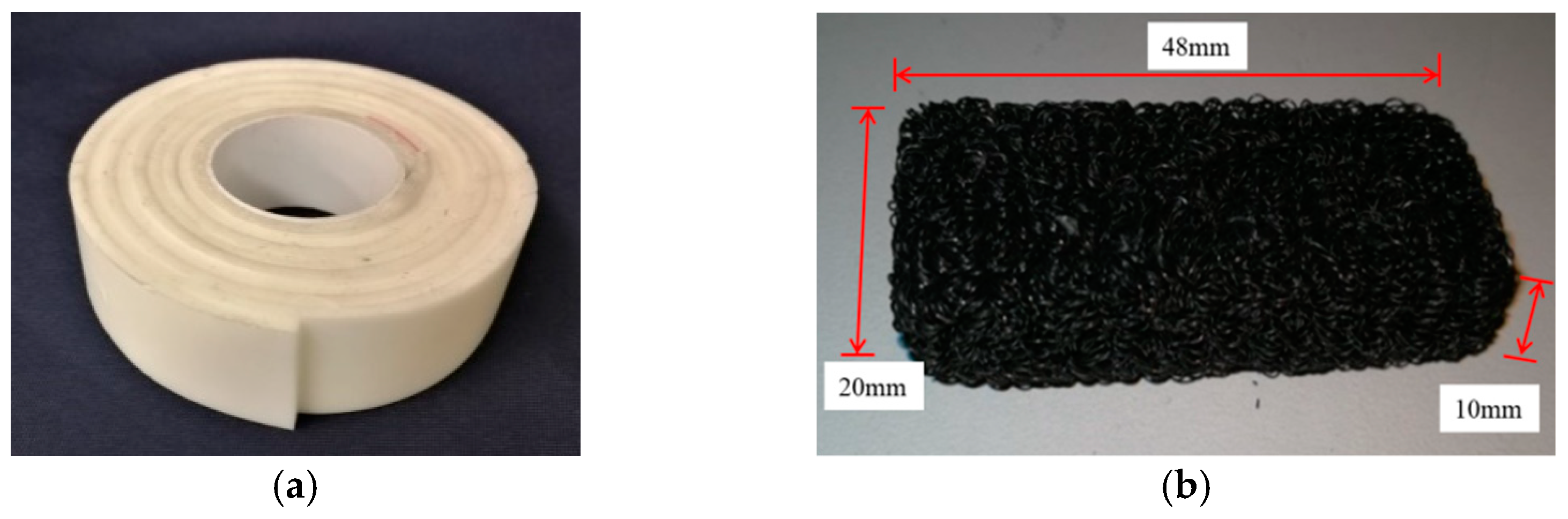
| Energy dissipating material | SMA | 48 × 20 × 10 (mm) | |
| Conditions | Time (20 mm to 2 mm) | Damping Ratio | ||
|---|---|---|---|---|
| Without Control | 26.5 s | 0.58% | ||
| With TMD Control | 48.8 s | 0.29% | ||
| With PTMD Control | VE | Spring Steel | 1.6 s | 10.4% |
| Pendulum | 2.85 s | 5.6% | ||
| SMA | Spring Steel | 2.5 s | 4.9% | |
| Pendulum | 2.9 s | 4.0% | ||
| Conditions | Resonant Frequency and Corresponding Maximum Displacement | Displacement Reduction Ratio Across the Entire Frequency Domain | Displacement and Reduction Ratio at Resonant Frequency | |||
|---|---|---|---|---|---|---|
| Without Control | 2.57 Hz | 18.90 mm | - | - | ||
| With TMD Control | 2.12 Hz, 3.02 Hz | 16.98 mm, 12.86 mm | 10% | 0.54 mm/97% | ||
| With PTMDs control | VE | Spring Steel | 2.46 Hz | 9.72 mm | 49% | 8.99 mm/52% |
| Pendulum | 2.46 Hz | 9.24 mm | 51% | 7.98 mm/58% | ||
| SMA | Spring Steel | 2.38 Hz, 2.83 Hz | 7.67 mm, 8.39 mm | 56% | 3.91 mm/79% | |
| Pendulum | 2.36 Hz, 2.75 Hz | 5.93 mm, 7.26 mm | 62% | 5.00 mm/74% | ||
© 2019 by the authors. Licensee MDPI, Basel, Switzerland. This article is an open access article distributed under the terms and conditions of the Creative Commons Attribution (CC BY) license (http://creativecommons.org/licenses/by/4.0/).
Share and Cite
Tan, J.; Jiang, J.; Liu, M.; Feng, Q.; Zhang, P.; Ho, S.C.M. Implementation of Shape Memory Alloy Sponge as Energy Dissipating Material on Pounding Tuned Mass Damper: An Experimental Investigation. Appl. Sci. 2019, 9, 1079. https://doi.org/10.3390/app9061079
Tan J, Jiang J, Liu M, Feng Q, Zhang P, Ho SCM. Implementation of Shape Memory Alloy Sponge as Energy Dissipating Material on Pounding Tuned Mass Damper: An Experimental Investigation. Applied Sciences. 2019; 9(6):1079. https://doi.org/10.3390/app9061079
Chicago/Turabian StyleTan, Jie, Jinwei Jiang, Min Liu, Qian Feng, Peng Zhang, and Siu Chun Michael Ho. 2019. "Implementation of Shape Memory Alloy Sponge as Energy Dissipating Material on Pounding Tuned Mass Damper: An Experimental Investigation" Applied Sciences 9, no. 6: 1079. https://doi.org/10.3390/app9061079