Article

Design and Kinematic Control of the Cable-Driven Hyper-Redundant Manipulator for Potential Underwater Applications

1
The State Key Laboratory of Fluid Power and Mechatronic Systems, Zhejiang University, Hangzhou 310027, China
2
Ocean College, Zhejiang University, Zhoushan 316021, China
3
Zhejiang Lab, Hangzhou 311100, China
4
Department of Electrical and Computer Engineering, Dalhousie University, P.O.Box 15000, Halifax, NS B3H 4R2, Canada
*
Author to whom correspondence should be addressed.
Appl. Sci. 2019, 9(6), 1142; https://doi.org/10.3390/app9061142
Submission received: 18 January 2019 / Revised: 9 March 2019 / Accepted: 10 March 2019 / Published: 18 March 2019
(This article belongs to the Special Issue Underwater Robots in Ocean and Coastal Applications)

Abstract

:
Underwater manipulators are important robotic tools in the exploration of the ocean environment. Up to now, most existing underwater manipulators are rigid and with fixed 5 or 7 degrees of freedom (DOF), which may not be very suitable for some complicated underwater scenarios (e.g., pipe networks, narrow deep cavities, etc.). The biomimetic concept of muscles and tendons is also considered as continuum manipulators, but load capacity and operation accuracy are their essential drawbacks and thus limit their practical applications. Recently, the cable-driven technique has been developed for manipulators, which can include numerous joints and hyper-redundant DOF to execute tasks with dexterity and adaptability and thus they have strong potential for these complex underwater applications. In this paper, the design of a novel cable-driven hyper-redundant manipulator (CDHRM) is introduced, which is driven by multiple cables passing through the tubular structure from the base to the end-effector, and the joint numbers can be extended and decided by the specific underwater task requirements. The kinematic analysis of the proposed CDHRM is given which includes two parts: the cable-joint kinematics and the joint-end kinematics. The geometric relationship between the cable length and the joint angles are derived via the established geometric model for the cable-joint kinematics, and the projection relationship between the joint angles and end-effector’s pose is established via the spatial coordinate transformation matrix for the joint-end kinematics. Thus, the complex mapping relationships among the cables, joints and end-effectors are clearly achieved. To implement precise control, the kinematic control scheme is developed for the CDHRM with series-parallel connections and hyper-redundancy to achieve good tracking performance. The experiment on a real CDHRM system with five joints is carried out and the results verify the accuracy of kinematics solution, and the effectiveness of the proposed control design. Particularly, three experiments are tested in the underwater environment, which verifies its good tracking performance, load carrying and grasping capacity.

1. Introduction

The research and development of the ocean is of great significance due to the abundant resources in the ocean environment [1,2,3,4]. With the development of advanced robotics and automation, the capacity to explore the ocean is enhanced by various underwater robots, which can replace human beings to achieve underwater detection and operations [5,6,7,8,9,10,11,12,13,14,15,16,17]. However up to now, most existing underwater manipulators are rigid and with fixed 5 or 7 degrees of freedom (DOF) [18,19], which may not be very suitable for some complicated underwater scenarios (e.g., pipe networks, narrow deep cavities, etc.). In view of the above limitation, the biomimetic concept of muscles and tendons is considered as continuum manipulators [20,21,22,23,24], which can achieve the flexible motion by elastic deformation. However, this kind of manipulator has slight load capacity, low operation accuracy, and is difficult to be precisely controlled due to its infinite DOFs and limited measurements. In recent years, the cable-driven technique has been also developed for the manipulators. With numerous joints and hyper-redundant DOF to execute tasks with dexterity and adaptability, the cable-driven hyper-redundant manipulator (CDHRM) has good obstacle avoidance capability, but also better load capacity and control precision. Thus, it has wide potential application fields, such as underwater rescue, marine exploration, minimally invasive surgery, aircraft assembly, nuclear inspection, etc. [25,26,27].
Different from the traditional rigid manipulator with serially connected links and actuated joints [28], the CDHRM no longer has the driving actuator in each joint. Instead, the cables, which pass through the tubular structure from the base to the end-effector, are used to drive joints, and all actuators are located in the base to drive these cables. Therefore, the manipulator joints do not need any seal, and can be used directly in the underwater environment. Moreover, the joint numbers of the CDHRM can be extended with regard to the specific underwater task requirements. Thus, various compact and ingenious motions can be achieved, especially when entering into confined spaces to implement tasks [29].
However, several issues need be solved for CDHRM’s practical application, including the mechanical design, kinematics, control, etc. [30]. For the mechanical design, due to the CDHRM’s unique operation mode in some typical confined underwater scenarios, the connections of each joint, the distribution of actuators and cables, and the lightweight design are difficult. Therefore, the mechanical design of CDHRM with flexible obstacle avoidance and strong load carrying capacity is challenging [31]. For the kinematics and control, since the motion of each joint with two DOFs is controlled by three cables, there exists complex mapping relationships and hyper-redundancy among the cables, joints and end-effector, which results in the complexity of kinematics and control [32,33].
Therefore, in view of the above issues, some relevant research has been conducted previously. Namely, Hannan et al. [34,35] designed a multi-section continuous-backbone robot, where the relationship between the cable length and joint angle was derived in detail, and the mapping relationship between the rope speed and joint angular velocity for kinematic modeling was established. The inverse kinematics were solved via the Jacobian matrix and the trajectory optimization of the grabbing process was carried out via the zero space vector of the Jacobian matrix [36,37,38,39]. KeJun Ning et al. [40,41,42] put forward a 3D hyper-redundant chain robot including the linked, identical modules and base module, where all joints are driven by cables and state controllable. But the drawback of such a manipulator is its long action cycle, where all passive joints share the common driving input, which have to be operated one by one. Simaan et al. [43,44] developed a cable-driven continuum manipulator for minimally invasive surgery of the throat. Byung-Ju Yi et al. [45] designed a continuum robot with good shape retention and space motion capability via the spring frame, which was driven by three cables with a diameter of 8 mm. British OC Robotics firstly commercialized the cable-driven hyper-redundant robotic arm named LaserSnake2, which was qualified for exploring space, nuclear energy, and construction, etc. [46]. Lu Chenguang et al. [47] developed a portable snake-like search and rescue apparatus that can be used ruins to inspect unreachable areas through gaps, but it was driven by manpower, which made it unsuitable for hazardous environments.
Though some researches has studied CDHRM, achieving compact and ingenious motion with good performance of CDHRM is still challenging [48]. As well, underwater applications have not yet been seen for CDHRM. Therefore, focuses on the mechanical design and kinematics of CDHRM, a typical CDHRM with 2 N -DOFs (N represents the number of the joints) is designed in this paper to implement tasks in some typical confined underwater scenarios and research its properties. For the driving subsystem, the CDHRM no longer has the driving actuator in each joint. Instead, the cables, which pass through the tubular structure from the base to the end-effector, are used for driving joints, and all actuators are located in the base to drive these cables. For the manipulator, the joint numbers of the CDHRM can be extended with regard to the task requirements. Therefore, various compact and ingenious motions can be achieved. Subsequently, the kinematic analysis of the proposed CDHRM is given, where the geometric relationship between the cable length and the joint angles are derived via the geometric model established for the cable-joint kinematics, and the projection relationship between the joint space and working space is established via the spatial coordinate transformation matrix for the joint-end kinematics. Thus, the complex mapping relationships between the cables, joints and end-effectors are clearly achieved. To implement precise control, the kinematic control scheme is developed to achieve good tracking performance for the CDHRM with series-parallel connections and hyper-redundancy. The platform experiment is implemented and also tried in the underwater environment, and the results show the accuracy of kinematics, the effectiveness of the control design and the good potential for underwater applications with good tracking, load carrying and grasping capacities.
The remainder of this paper is organized as follows. Section 2 presents the mechanical design of the CDHRM. Section 3 describes the kinematics of the CDHRM. A kinematic control scheme is then designed in Section 4. Section 5 implements the experiment and Section 6 concludes our work.

2. Mechanical Design of CDHRM

2.1. Overall Design of CDHRM

To meet the task requirements in a typical confined underwater scenario, the characteristics which are required to be considered in the design of the CDHRM include being lightweight, strong obstacle avoidance, high flexibility and strong load capacity.
A general mechanical design of a CDHRM is shown in Figure 1a. It is an integrated structure consisting of a driving subsystem and manipulator. The driving subsystem contains the cables and actuators mounted on the base, and the adjacent joints in the manipulator are coupled with each other by a universal joint. The joint number can be extended with regard to practical tasks, which can greatly improve the flexibility of the CDHRM.
Each cable is used to pass through the joints to connect the end-effector and driving subsystem. The rotational motions of each joint can be achieved by pulling and pushing cables passing through the holes pierced in the tubular structure, which is controlled by the rotation of the actuator. And the driving subsystem (shown in Figure 1b) is used to convert the rotation of actuator to the rectilinear motion of cables. The linear magnetic encoders are mounted on the driving subsystem to measure the cable’s displacement.

2.2. Manipulator Design

Considering the working conditions of CDHRMs in typical confined underwater scenarios, the aluminum alloy with high strength and low density are used as the materials for the CDRHM, and the tubular structure in Figure 1c is designed to be hollow and thin-walled, which reduces the weight of the CDHRM. The end plate (shown in Figure 1d), which is used to connect the tubular structure and universal joint, has a series of through-holes in the circumferential direction for the pass of cables.

2.3. Driving Subsystem Design

As shown in Figure 1b, the driving subsystem contains the actuator with high power density and a large decelerating white reducer, bearing bracket, guide rods, leading screw, slider and linear magnetic encoder. With the satisfaction of functional requirements, the driving subsystem is designed to be as compact as possible and easy to install and maintain, where the parameters are determined by the joint angle. The driving subsystems are circumferentially distributed, which connect the actuators and the cables, converting the rotation of actuator to the rectilinear motion of cables.

3. Kinematic Analysis of CDHRM

3.1. Multilevel Mapping Relationships of CDHRM

According to the mechanical design, the multilevel mapping relationships of CDHRM can be described in Figure 2, which can be divided into cable-joint kinematics and joint-end kinematics, where the relationship between the forward and inverse kinematics is expressed as: driving space—joint space—working space. For cable-joint kinematics, the geometric relationship between the cable length and the joint angle are developed via the established geometric model. Subsequently, for joint-end kinematics, the projection relationship between the joint angles and end-effector’s pose is established via the spatial coordinate transformation matrix.
To establish multilevel mapping relationships of the CDHRM, a geometric model and coordinate system is created as shown in Figure 3a,b, where the Figure 3a represents the geometric model when the joint is in the odd condition, similarly the Figure 3b represents the geometric model when the joint is in the even condition. The frames I i and J i are created at the center of two tubular structures, and another frame U i is created at the center of the universal joint.

3.2. Cable-Joint Kinematics

The length of each cable consists of the length inside the tubular structure and the length between adjacent joints. The cable length inside the tubular structure is equal to the length of the tubular structure, which is a measurable constant. The length between adjacent joints is derived with regard to the joint angles, which can be calculated as follows:
Suppose that the manipulator has N joints, H represents the length of each tubular structure, R represents the radius of each tubular structure, D represents the distance from the tubular structure to the center of universal joint. To establish the relationship between the length between adjacent joints and the joint angles, the transformation between the adjacent joint frames I i and J i can be derived as (1) and (2), which are shown at the top of next page, where if i (i = 1,2,…,N) is an odd number, the transformation is (1) otherwise the transformation is (2).
J I T = t r a n s l D , 0 , 0   t r o t z α i   t r o t y β i   t r a n s l D , 0 , 0 = c o s α i c o s β i s i n α i s i n β i c o s α i D + D c o s α i c o s β i c o s β i s i n α i c o s α i s i n β i s i n α i D c o s β i s i n α i s i n β i 0 c o s β i D s i n β i 0 0 0 1
J I T = t r a n s l D , 0 , 0   t r o t y β i   t r o t z α i   t r a n s l D , 0 , 0 = c o s β i c o s α i c o s β i s i n α i s i n β i D + D c o s β i c o s α i s i n α i c o s α i 0 D s i n α i s i n β i c o s α i s i n β i s i n α i c o s β i D s i n β i c o s α i 0 0 0 1
where t r a n s l ( ) represents the translation function, t r o t y ( ) and t r o t z ( ) represent the rotation function refer to y-axis and z-axis, α i and β i represent counterclockwise rotation angle of the i-th joint around the z-axis and y-axis.
The counterclockwise mounting angle ϕ j , k of the j-th (j = 1,2,3) cable actuating the k-th (k = 1,2,…,N) joint can be derived in (3), The p i , j , k is the mounting position of the j th cable actuating the k th joint at the I i frame, which can be derived in (4).
ϕ j , k = k × 360 M + ( j 1 ) × 120
p i , j , k = [ 0 , R × cos ( ϕ j , k ) , R × sin ( ϕ j , k ) ] T
where M represents the number of the holes at the end plate.
Define l i j k as the length of the j th cable actuating the k th joint between the frames I i and J i , L j k as the total length of the j th cable actuating the k th joint, which can be derived as follows:
l i , j , k = | | J I T × p i , j , k p i , j , k | |
L j k = i = 1 k ( l i j k + H )
Therefore, the geometric relationship between cable length ( L j k ) and joint angle α i and β i can be derived with regard to (1)–(6).

3.3. Joint-End Kinematics

To establish the projection relationship between the joint space and working space, the relationship between the coordinate frame of each joint are derived via spatial coordinate transformation matrix. As shown in Figure 3a,b, the coordinate system I i is established at the end of the ith joint.
The pose of the k th joint frame I k with respect to the base frame I 0 can be expressed as follows:
0 k T = i = 1 k ( J I T × t r a n s ( H , 0 , 0 ) )
where J I T represents the corresponding homogeneous transformation matrix between adjacent frames I i and J i , which can be derived with regard to (1) and (2).
The key to realizing the manipulation of a CDHRM in a typical confined underwater scenario is the fast online solution of each joint angles α i and β i according to the change of the end-effector’s pose. However, due to the large number of DOFs, the inverse kinematics of CDHRM [49] is difficult to derive via numerical methods. As it will cost a large amount of computational time to solve the pseudo-inverse of the Jacobian matrix with the increase of DOFs, this has a negative effect on the CDHRM’s real-time control. With regard to the special motion characteristics of CDHRM, a geometric method with high-efficiency is proposed as shown in Figure 4.
The desired pose of the end-effector is determined by the task trajectory of some typical confined underwater scenarios. Then the desired pose of the joint frame I i 1 can be determined with regard to (7). With the desired pose of the joint frame I i 1 , which joint to be adjusted can be determined. As this method does not need to solve all the joint angles in a certain task, it has lower computation cost and is suitable for real-time control.

4. Kinematic Control of a CDHRM

In a CDHRM, each joint is controlled by three cables, but with the motions of two DOFs (yaw and pitch in the axial direction). Besides, the number of the manipulator’s DOFs is higher than end-effector’s DOFs with the increasing of joint numbers according to specific task requirements. Therefore, a CDHRM has the characteristic of hyper-redundancy, which makes it difficult to model and control. Moreover, there is an error between the practical kinematics and the theoretical kinematics of the CDHRM when working in typical confined underwater scenarios (e.g., pipe networks, narrow deep cavities, etc.).
To achieve good tracking performance of the desired task trajectory in some typical underwater scenarios, a control scheme of a CDHRM is designed in this section, which is shown in Figure 5. In details, the desired angles α d i and β d i are calculated by the joint-end kinematics (Figure 4) with regard to the desired end-effector’s pose X ˜ d , which can be planned with the desired trajectory X d in the practical task. The desired cable length l d r is calculated by the cable-joint kinematics (1)–(6) with α d i , β d i . The practical cable length l r is measured by the linear magnetic encoder mounted on the driving subsystem. Thus, a closed-loop controller u r , where the actuators are working in the speed-loop, can be designed as follows:
u r = K p l d r l r + K c 0 t l d r l r d t + K d l ˙ d r l ˙ r
where r represents the r-th cable, and r = 1 , , 3 N , K p , K c , K d are the control parameters, which can be selected with regard to the tracking performance.

5. Experiment

5.1. Prototype

According to the mechanical design of the CDHRM in Section 2, a real CDHRM system with five joints as shown in Figure 6a is fabricated, where the parameters and equipment selection can be specified in Table 1 and Table 2. And the working space is calculated with kinematics derived in Section 3, which is shown in Figure 6b.

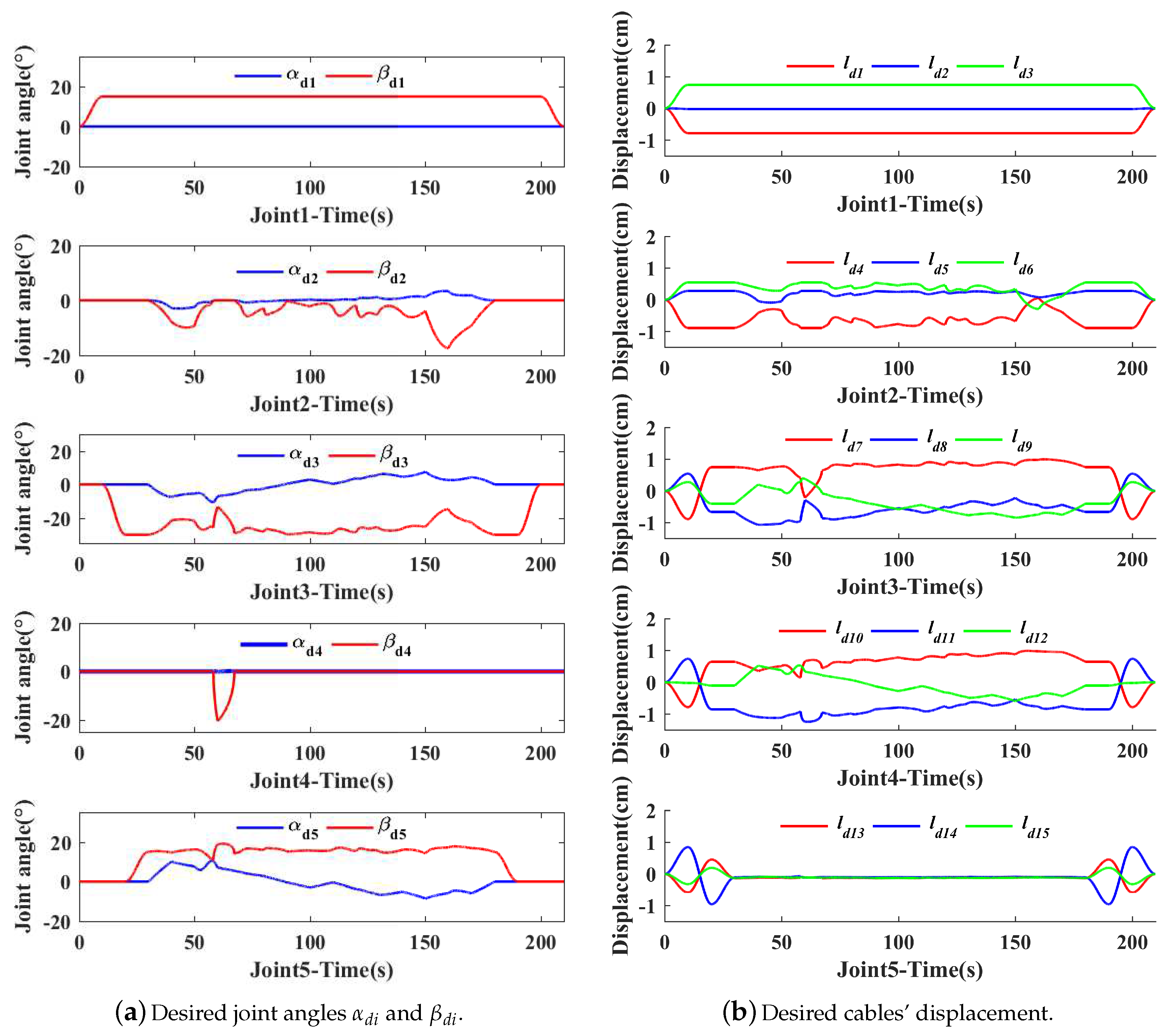
5.2. Experiment of Writing on a White Board

In order to verify the accuracy of the kinematics and effectiveness of the control scheme, the experiment of writing on a white board is implemented, where the controller (8) is used and the parameters can be selected as K p = 10 , K c = 10 , K d = 1 . The desired writing trajectory of end-effector is selected as Figure 7a.
With the desired joint angles α d i and β d i (shown in Figure 8a), which are calculated according to the end-to-joint kinematics (Figure 4) with desired writing trajectory X d (shown in Figure 7a), the end-effector’s trajectory solution can be calculated by joint-to-end kinematics (7), as shown in Figure 7b, thus verifying the accuracy of kinematics (1)–(7).
With the accurate kinematics, the controller (8) is implemented in the experiment, where the experiment process can be seen in Figure 7c, and the experimental results are shown in Figure 9. To quantify the tracking performance of CDHRM more clearly, the RMSE (root mean square error) of the desired cable displacement l d r (shown in Figure 8b) and the practical cable displacement l r (shown in Figure 9a) are calculated, and the results are shown in Table 3. According to the Figure 9b and Table 3, the CDHRM system has the effective tracking performance, where the tracking errors e r (shown in Figure 9b) of the desired cable displacement l d r and the practical cable displacement l r are quite small ( 10 4 cm, Table 3). Therefore, the accuracy of kinematics and the effectiveness of the control design are verified.

5.3. Experiment in the Underwater Environment

In this section, based on the accuracy of kinematics and the effectiveness of the control design, the CDHRM is tried to explore the potential application for some complicated scenarios in the underwater environment, which is provided by a container (length: 60 cm, width: 40 cm, height: 40 cm) filled with water (78.26 L). The controller (8) is used and the parameters can be selected as K p = 10 , K c = 10 , K d = 1 , which is consistent with the parameter setting of Section 5.2. Three experiment sets are designed in the underwater environment, which are as follows:
  • SET1: Writing without load
  • SET2: Writing with load
  • SET3: Grasping objects

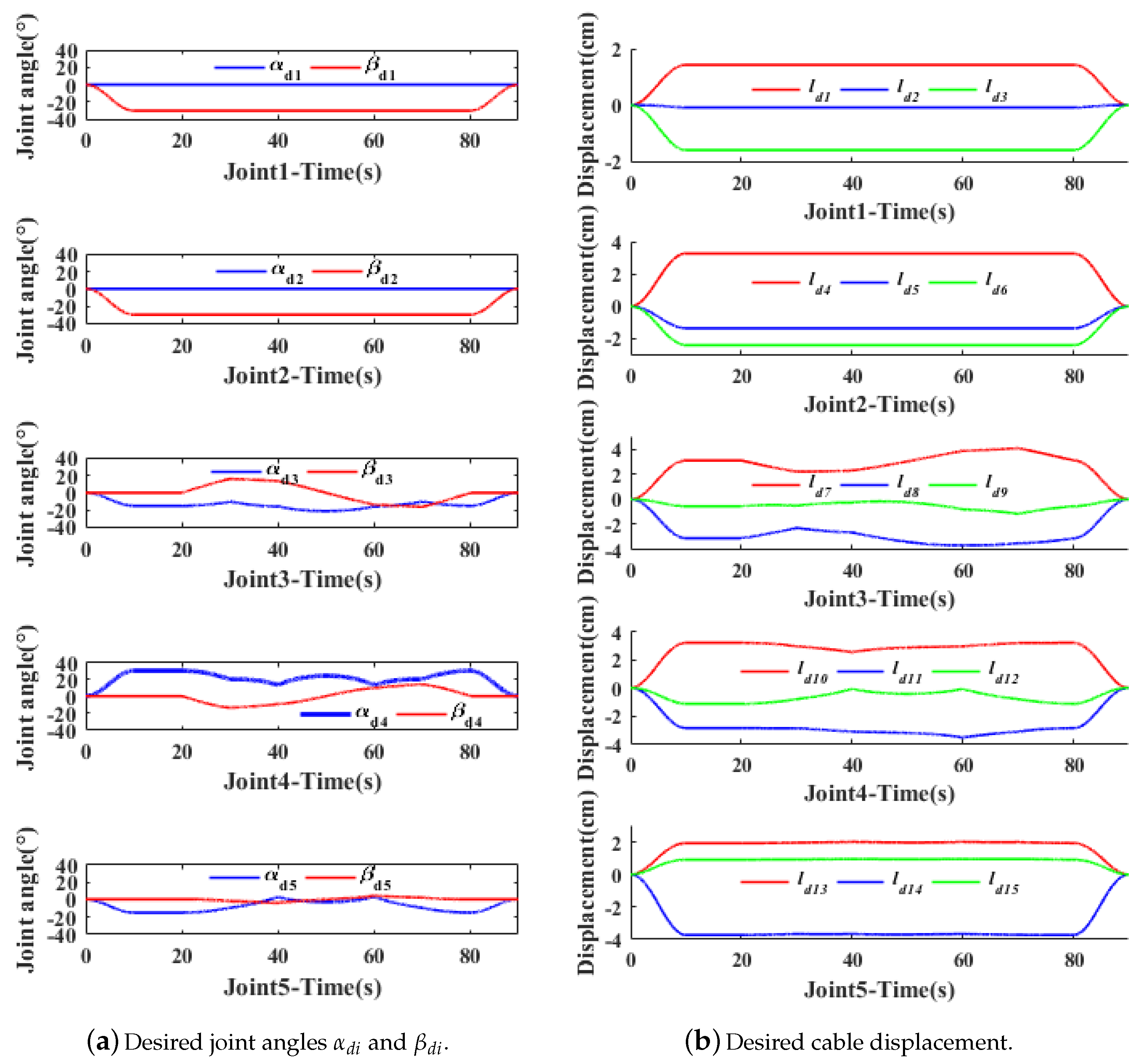
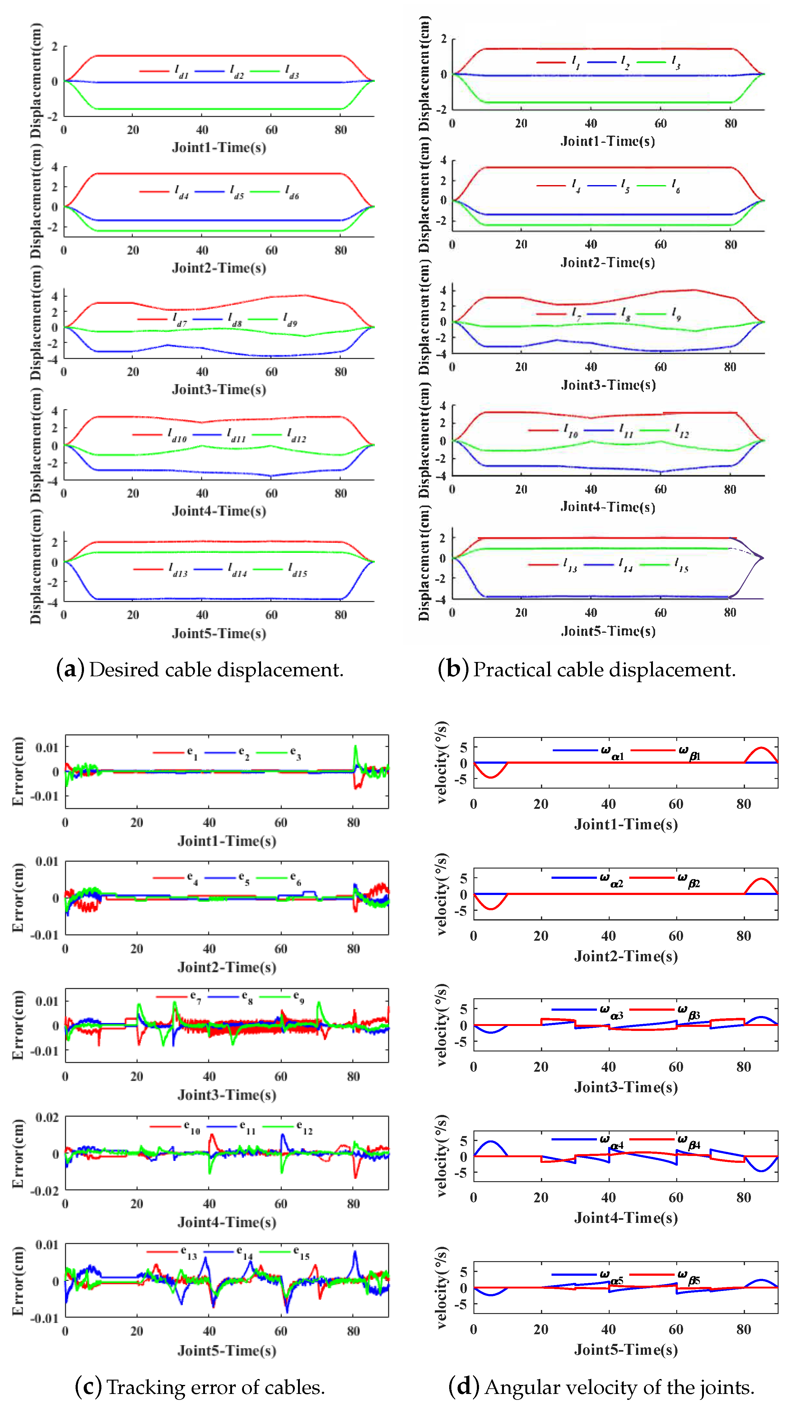
5.3.1. Experiment of SET1 in the Underwater Environment

The desired writing trajectory of end-effector in SET1 is selected as Figure 10a. With the desired joint angles α d i and β d i (shown in Figure 11a), which are calculated according to the end-to-joint kinematics (Figure 4). With the accurate kinematics, the controller (8) is implemented in the underwater experiment, where the practical writing trajectory of writing trajectory and the experiment process can be seen in Figure 10b,c.
According to the experiment results shown in Figure 12 and Table 3, the CDHRM system has the great tracking performance, where the tracking errors e r (shown in Figure 12b) of the desired cable displacement l d r and the practical cable displacement l r are quite small ( 10 4 cm, shown in Table 3), thus the good tracking performance in the underwater environment are verified.

5.3.2. Experiment of SET2 in the Underwater Environment

To verify the load carrying capacity of the CDHRM, the SET2 with the load of 500 g is implemented, where the load is installed in the end of the CDHRM. To maintain a fair experiment, the desired writing trajectory of end-effector is selected as the same as SET1 as shown in Figure 10a. The experiment process can be seen in Figure 13.
According to the experiment results shown in Figure 14 and Table 3, the CDHRM system has the good tracking performance with the load in the end-effector, where the tracking errors e r (shown in Figure 14c) of the desired cable displacement l d r and the practical cable displacement l r are as small as the errors in SET1 ( 10 4 cm, shown in Table 3), which means the load has little effect on the working performance for the CDHRM. Therefore, the effective load carrying capacity of CDHRM is verified.

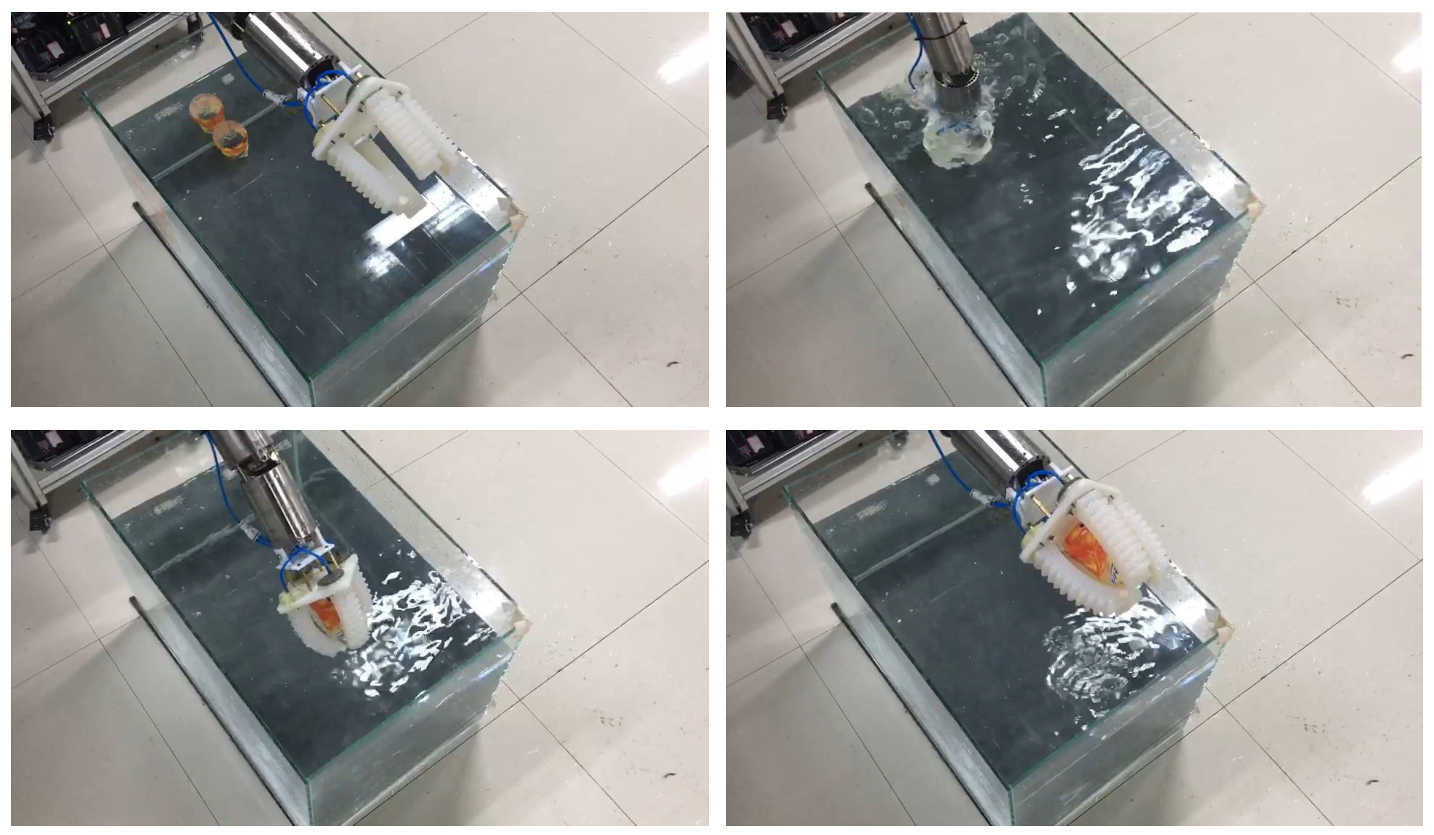
5.3.3. Experiment of SET3 in the Underwater Environment

To verify the grasping capacity in the underwater environment, the SET3 is implemented, where a gripper is installed in the end-effector of the CDHRM to grasp the objects in the bottom of container. The experiment process is shown in Figure 15.
According to Figure 15, an object was grasped from the bottom of the container successfully. With the experiment results shown in Figure 16 and Table 3, the CDHRM system has effective grasping performance, where the tracking errors e r (shown in Figure 16c) of the desired cable displacement l d r and the practical cable displacement l r are quite small ( 10 4 cm, shown in Table 3). Therefore, the effective load carrying capacity of CDHRM is verified.
With three experiments in the underwater environment tried in this section, it can be seen that the CDHRM has good tracking performance, load carrying and grasping capacity. Therefore, the potential for underwater applications of the designed CDHRM are verified.
Moreover, an experiment data comparison between different CDHRMs is implemented and the results are shown in Table 4. It can be seen that the CDHRM designed in this paper has similarly effective load carrying and tracking performance when working in an underwater environment.

6. Conclusions

In this paper, a novel CDHRM is developed to implement the tasks in some typical confined scenarios (e.g., pipe networks, narrow deep cavities, etc.), which is driven by multiple cables passing through the tubular structure from the base to the end-effector, and the joint numbers can be extended according to the specific task requirements. For the kinematic analysis of the proposed CDHRM, the cable-joint kinematics is established via the geometric model between the cable length and the joint angles, and the joint-end kinematics are established via the spatial coordinate transformation matrix. Thus, the mapping relationships among the cables, joints and end-effectors are clearly described. For the CDHRM with series-parallel connections and hyper-redundancy, a kinematic control scheme is developed and carried out for the practical experiment of writing on a board. The results verify the accuracy of kinematics and the effectiveness of the proposed control design.
Furthermore, based on the developed kinematic and control design, three experiments in the underwater environment are implemented, and the results verify that the designed CDHRM has good tracking, load carrying and grasping capacity, which has a good potential application prospects for complicated scenarios in an underwater environment.

Author Contributions

Conceptualization, J.T. and Z.C.; methodology, J.T. and Z.C.; software, J.L.; validation, Y.Z., F.H., J.L. and W.S.; formal analysis, Z.C.; investigation, J.L. and Z.C.; resources, W.S. and Z.C.; data curation, J.L.; writing—original draft preparation, Y.Z.; writing —review and editing, F.H. and Z.C.; visualization, S.Z.; supervision, S.Z. and J.G.; project administration, J.T. and Z.C.; funding acquisition, W.S. and Z.C.

Funding

This work is funded by the Natural Science Foundation of Zhejiang Province, China (No. LY19E050016), and National Natural Science Foundation of China (No.51705452 and No.61603332).

Conflicts of Interest

The authors declare no conflict of interest.

References

  1. Liu, P.; Bose, N.; Chen, K.; Chen, K.; Xu, Y. Development and optimization of dual-mode propellers for renewable energy. Renew. Energy 2018, 119, 566–576. [Google Scholar] [CrossRef]
  2. Brito, M.P.; Lewis, R.S.; Bose, N. Gwyn Griffiths Adaptive Autonomous Underwater Vehicles: An Assessment of Their Effectiveness for Oceanographic Applications. IEEE Trans. Eng. Manag. 2018, 66, 98–111. [Google Scholar] [CrossRef]
  3. Lewis, R.; Bose, N.; Lewis, S.; King, P.; Walker, D.; Devillers, R.; Ridgley, N.; Husain, T.; Munroe, J.; Vardy, A. MERLIN—A decade of large AUV experience at Memorial University of Newfoundland. In Proceedings of the 2016 IEEE/OES Autonomous Underwater Vehicles (AUV), Tokyo, Japan, 6–9 November 2016. [Google Scholar]
  4. Alexander, P.; Duncan, A.; Bose, N.; Wilkes, D.; Lewis, R.; Souza, P. Noise characterisation of the Aurora Australis while stationary in Antarctic sea ice. Ocean Eng. 2014, 82, 52–64. [Google Scholar] [CrossRef]
  5. Wang, Y.; Yan, F.; Chen, J.; Ju, F.; Chen, B. A new adaptive time-delay control scheme for cable-driven manipulators. IEEE Trans. Ind. Inf. 2018. [Google Scholar] [CrossRef]
  6. Chen, Z.; Yao, B.; Wang, Q. Accurate motion control of linear motors with adaptive robust compensation of nonlinear electromagnetic field effect. IEEE/ASME Trans. Mechatron. 2013, 18, 1122–1129. [Google Scholar] [CrossRef]
  7. Wang, Y.; Chen, J.; Yan, F.; Zhu, K.; Chen, B. Adaptive super-twisting fractional-order nonsingular terminal sliding mode control of cable-driven manipulators. ISA Trans. 2019, 86, 163–180. [Google Scholar] [CrossRef]
  8. Chen, Z.; Yao, B.; Wang, Q. μ-synthesis based adaptive robust control of linear motor driven stages with high-frequency dynamics: A case study. IEEE/ASME Trans. Mechatron. 2015, 20, 1482–1490. [Google Scholar] [CrossRef]
  9. Yuan, M.; Chen, Z.; Yao, B.; Zhu, X. Time optimal contouring control of industrial biaxial gantry: A high-efficient analytical solution of trajectory planning. IEEE/ASME Trans. Mechatron. 2017, 22, 247–257. [Google Scholar] [CrossRef]
  10. Chen, Z.; Pan, Y.J.; Gu, J. Integrated Adaptive Robust Control for Multilateral Teleoperation Systems under Arbitrary Time Delays. Int. J. Robust Nonlinear Control. 2016, 26, 2708–2728. [Google Scholar] [CrossRef]
  11. Sun, W.; Liu, Y.; Gao, H. Constrained sampled-data ARC for a class of cascaded nonlinear systems with applications to motor-servo systems. IEEE Trans. Ind. Inform. 2019, 15, 766–776. [Google Scholar] [CrossRef]
  12. Wang, Y.; Li, B.; Yan, F.; Chen, B. Practical adaptive fractional-order nonsingular terminal sliding mode control for a cable-driven manipulator. Int. J. Robust Nonlinear Control. 2019, 29, 1396–1417. [Google Scholar] [CrossRef]
  13. Sun, W.; Zhang, J.; Liu, Z. Two-time-scale redesign for anti-lock braking systems of ground vehicles. IEEE Trans. Ind. Electron. 2019, 66, 4577–4586. [Google Scholar] [CrossRef]
  14. Chen, Z.; Huang, F.; Yang, C.; Yao, B. Adaptive fuzzy backstepping control for stable nonlinear bilateral teleoperation manipulators with enhanced transparency performance. IEEE Trans. Ind. Electron. 2019. [Google Scholar] [CrossRef]
  15. Yao, J.; Deng, W. Active disturbance rejection adaptive control of hydraulic servo systems. IEEE Trans. Ind. Electron. 2017, 64, 8023–8032. [Google Scholar] [CrossRef]
  16. Yao, J.; Deng, W.; Jiao, Z. RISE-Based Adaptive Control of Hydraulic Systems with Asymptotic Tracking. IEEE Trans. Autom. Sci. Eng. 2017, 14, 1524–1531. [Google Scholar] [CrossRef]
  17. Li, C.; Li, C.; Chen, Z.; Yao, B. Advanced synchronization control of a dual-linear-motor-driven gantry with rotational dynamics. IEEE Trans. Ind. Electron. 2018, 65, 7526–7535. [Google Scholar] [CrossRef]
  18. Barbalata, C.; Dunnigan, M.W.; Petillot, Y. Coupled and Decoupled Force/Motion Controllers for an Underwater Vehicle-Manipulator System. J. Mar. Sci. Eng. 2018, 6, 96. [Google Scholar] [CrossRef]
  19. Barbieri, L.; Bruno, F.; Gallo, A.; Muzzupappa, M.; Russo, M.L. Design, prototyping and testing of a modular small-sized underwater robotic arm controlled through a Master-Slave approach. Ocean Eng. 2018, 158, 253–262. [Google Scholar] [CrossRef]
  20. Cianchetti, M.; Laschi, C.; Menciassi, A.; Dario, P. Biomedical applications of soft robotics. Nat. Rev. Mater. 2018, 3, 143–153. [Google Scholar] [CrossRef]
  21. Dalvand, M.M.; Nahavandi, S.; Howe, R.D. An Analytical Loading Model for n-Tendon Continuum Robots. IEEE Trans. Robot. 2018, 34, 1215–1225. [Google Scholar] [CrossRef]
  22. Jia, H.; Huang, Z.; Fei, Z.; Dyson, P.J.; Zheng, Z.; Wang, X. Bilayered Polyurethane/Dipole-dipole and H-bonding Interaction Reinforced Hydrogels as Thermo-responsive Soft Manipulators. J. Mater. Chem. B 2017, 5, 8193–8199. [Google Scholar] [CrossRef]
  23. Camarillo, D.B.; Carlson, C.R.; Salisbury, J.K. Configuration Tracking for Continuum Manipulators with Coupled Tendon Drive. IEEE Trans. Robot. 2009, 25, 798–808. [Google Scholar] [CrossRef]
  24. Navarro-Alarcon, D.; Yip, H.M.; Wang, Z.; Zhong, F.; Liu, Y.-H.; Zhang, T.; Li, P. Automatic 3-D Manipulation of Soft Objects by Robotic Arms With an Adaptive Deformation Model. IEEE Trans. Robot. 2016, 32, 429–441. [Google Scholar] [CrossRef]
  25. Choi, D.; Yi, B.; Kim, W. Design of a spring backbone micro endoscope. In Proceedings of the 2007 IEEE/RSJ International Conference on Intelligent Robots and Systems, San Diego, CA, USA, 29 October–2 November 2007; pp. 1815–1821. [Google Scholar]
  26. Ning, K.; Woergoetter, F. A Novel Concept for Building a Hyper-Redundant Chain Robot. IEEE Trans. Robot. 2009, 25, 1237–1248. [Google Scholar] [CrossRef]
  27. Hu, H.; Wang, P.; Zhao, B.; Li, M.; Sun, L. Design of a novel snake-like robotic colonoscope. In Proceedings of the 2009 IEEE International Conference on Robotics and Biomimetics (ROBIO), Guilin, China, 19–23 December 2009; pp. 1957–1961. [Google Scholar]
  28. Walker, I.D.; Hannan, M.W. A novel ’elephant’s trunk’ robot. In Proceedings of the 1999 IEEE/ASME International Conference on Advanced Intelligent Mechatronics, Atlanta, GA, USA, 19–23 September 1999; pp. 410–415. [Google Scholar]
  29. Lau, D.; Oetomo, D.; Halgamuge, S.K. Inverse Dynamics of Multilink Cable-Driven Manipulators with the Consideration of Joint Interaction Forces and Moments. IEEE Trans. Robot. 2015, 31, 479–488. [Google Scholar] [CrossRef]
  30. Roy, R.; Wang, L.; Simaan, N. Modeling and Estimation of Friction, Extension, and Coupling Effects in Multisegment Continuum Robots. IEEE/ASME Trans. Mechatron. 2017, 22, 909–920. [Google Scholar] [CrossRef]
  31. Xu, D.; Li, E.; Liang, Z. Kinematics and statics analysis of a novel cable-driven snake arm robot. In Proceedings of the 2017 Chinese Automation Congress (CAC), Jinan, China, 20–22 October 2017; pp. 439–444. [Google Scholar]
  32. Lau, D.; Oetomo, D.; Halgamuge, S.K. Generalized Modeling of Multilink Cable-Driven Manipulators with Arbitrary Routing Using the Cable-Routing Matrix. IEEE Trans. Robot. 2013, 29, 1102–1113. [Google Scholar] [CrossRef]
  33. Hassan, M.; Khajepour, A. Analysis of Bounded Cable Tensions in Cable-Actuated Parallel Manipulators. IEEE Trans. Robot. 2011, 27, 891–900. [Google Scholar] [CrossRef]
  34. Hannan, M.W.; Walker, I.D. Analysis and initial experiments for a novel elephant’s trunk robot. In Proceedings of the 2000 IEEE/RSJ International Conference on Intelligent Robots and Systems (IROS 2000), Takamatsu, Japan, 31 October–5 November 2000; pp. 330–337. [Google Scholar]
  35. Hannan, M.W.; Walker, I.D. Kinematics and the implementation of an elephant’s trunk manipulator and other continuum style robots. J. Robot. Syst. 2003, 20, 45–63. [Google Scholar] [CrossRef]
  36. McMahan, W.; Jones, B.A.; Walker, I.D. Design and implementation of a multi-section continuum robot: Air-Octor. In Proceedings of the 2005 IEEE/RSJ International Conference on Intelligent Robots and Systems, Edmonton, ALT, Cancda, 2–6 August 2005; pp. 2578–2585. [Google Scholar]
  37. Gravagne, I.A.; Walker, I.D. On the kinematics of remotely-actuated continuum robots. In Proceedings of the 2000 ICRA—Millennium Conference—IEEE International Conference on Robotics and Automation. Symposia Proceedings, San Francisco, CA, USA, 24–28 April 2000; Volume 3, pp. 2544–2550. [Google Scholar]
  38. Gravagne, I.A.; Walker, I.D. Kinematic transformations for remotely-actuated planar continuum robots. In Proceedings of the 2000 ICRA—Millennium Conference—IEEE International Conference on Robotics and Automation. Symposia Proceedings, San Francisco, CA, USA, 24–28 April 2000; Volume 1, pp. 19–26. [Google Scholar]
  39. Wooten, M.; Frazelle, C.; Walker, I.D.; Kapadia, A.; Lee, J.H. Exploration and Inspection with Vine-Inspired Continuum Robots. In Proceedings of the 2018 IEEE International Conference on Robotics and Automation (ICRA), Brisbane, QLD, Australia, 21–25 May 2018; pp. 1–5. [Google Scholar]
  40. Ning, K.; Woergoetter, F. A DOF state controllable driving shared solution for building a hyper-redundant chain robot. In Proceedings of the 2009 IEEE/RSJ International Conference on Intelligent Robots and Systems, St. Louis, MO, USA, 10–15 October 2009; pp. 5880–5885. [Google Scholar]
  41. Ning, K.; Woergoetter, F. To Paint What Is Seen: A System Implementation of a Novel Conceptual Hyper-Redundant Chain Robot with Monocular Vision. In Proceedings of the ISR 2010 (41st International Symposium on Robotics) and ROBOTIK 2010 (6th German Conference on Robotics), Munich, Germany, 7–9 June 2010; pp. 1–6. [Google Scholar]
  42. Ning, K.; Woergoetter, F. Control System Development for a Novel Wire-Driven Hyper-Redundant Chain Robot, 3D-Trunk. IEEE/ASME Trans. Mechatron. 2012, 17, 949–959. [Google Scholar] [CrossRef]
  43. Simaan, N. Snake-Like Units Using Flexible Backbones and Actuation Redundancy for Enhanced Miniaturization. In Proceedings of the 2005 IEEE International Conference on Robotics and Automation, Barcelona, Spain, 18–22 April 2005; pp. 3012–3017. [Google Scholar]
  44. Xu, K.; Simaan, N. Analytic Formulation for Kinematics, Statics, and Shape Restoration of Multibackbone Continuum Robots Via Elliptic Integrals. ASME J. Mechan. Robot. 2009, 2, 011006. [Google Scholar] [CrossRef]
  45. Yoon, H.; Yi, B. A 4-DOF flexible continuum robot using a spring backbone. In Proceedings of the 2009 International Conference on Mechatronics and Automation, Changchun, China, 9–12 August 2009; pp. 1249–1254. [Google Scholar]
  46. Buckingham, R.; Graham, A. Reaching the unreachable snake arm robots. In Proceedings of the International Symposium of Robotics, Siena, Italy, 19–22 October 2003; Available online: www.ocrobotics.com (accessed on 14 March 2019).
  47. Chenguang, L.; Mingyuan, Z.; Jianyong, L.; Long, W. Design of a portable snake-like search and rescue apparatus used in the gap. In Proceedings of the 2011 International Conference on Mechatronic Science, Electric Engineering and Computer (MEC), Jilin, China, 19–22 August 2011; pp. 676–679. [Google Scholar]
  48. Moses, M.S.; Murphy, R.J.; Kutzer, M.D.M.; Armand, M. Modeling Cable and Guide Channel Interaction in a High-Strength Cable-Driven Continuum Manipulator. IEEE/ASME Trans. Mechatron. 2015, 20, 2876–2889. [Google Scholar] [CrossRef] [PubMed] [Green Version]
  49. Xu, W.; Mu, Z.; Liu, T.; Liang, B. A modified modal method for solving the mission-oriented inverse kinematics of hyper-redundant space manipulators for on-orbit servicing. Acta Astronaut. 2017, 139, 54–66. [Google Scholar] [CrossRef]
  50. Xu, W.; Liu, T.; Li, Y. Kinematics, Dynamics, and Control of a Cable-Driven Hyper-Redundant Manipulator. IEEE/ASME Trans. Mechatron. 2018, 23, 1693–1704. [Google Scholar] [CrossRef]
  51. Tang, L.; Wang, J.G.; Zheng, Y.; Gu, G.; Zhu, L.; Zhu, X. Design of a cable-driven hyper-redundant robot with experimental validation. Int. J. Adv. Robot. Syst. 2018, 14, 1–12. [Google Scholar] [CrossRef]
Figure 1. Mechanical design of a cable-driven hyper-redundant manipulator (CDHRM).
Applsci 09 01142 g001aApplsci 09 01142 g001b
Figure 2. Multilevel mapping relationships of the manipulator.
Applsci 09 01142 g002
Figure 3. Geometric model of the universal joint.
Applsci 09 01142 g003
Figure 4. Inverse kinematics of CDHRM.
Applsci 09 01142 g004
Figure 5. PID-based control scheme of CDHRM.
Applsci 09 01142 g005
Figure 6. The real designed CDHRM system and its working space.
Applsci 09 01142 g006
Figure 7. End-effector trajectory and experiment process of writing on a white board.
Applsci 09 01142 g007
Figure 8. Desired joint angles and cables’ displacement of writing on a white board.
Applsci 09 01142 g008
Figure 9. Experimental results of writing on a white board.
Applsci 09 01142 g009aApplsci 09 01142 g009b
Figure 10. End-effector trajectory and experiment process of SET1 in the underwater environment.
Applsci 09 01142 g010aApplsci 09 01142 g010b
Figure 11. Desired joint angles and cable displacement of SET1 in the underwater environment.
Applsci 09 01142 g011
Figure 12. Experiment result of SET1 in the underwater environment.
Applsci 09 01142 g012
Figure 13. Experiment of SET2 in the underwater environment.
Applsci 09 01142 g013
Figure 14. Experiment result of SET2 in the underwater environment.
Applsci 09 01142 g014aApplsci 09 01142 g014b
Figure 15. Experiment of SET3 in the underwater environment.
Applsci 09 01142 g015
Figure 16. Experiment result of SET3 in the underwater environment.
Applsci 09 01142 g016
Table 1. The parameters of the CDHRM system.
SymbolPropertyValue
RRadius of tubular structure33.8 mm
DDistance from the tubular structure to universal joint12 mm
HLength of tubular structure106 mm
NNumber of joints5
Table 2. Equipment model selection.
EquipmentEquipment ModelQuantity
ActuatorsMaxon EC-max 3015
GearsPlanetary Gearhead GP 32 C15
Data acquisition deviceQuanser QPID1
Serve controllerESCON 50/5 40951015
Linear magnetic encoderLM1015
Table 3. RMSE of cable displacement l ( × 10 4 cm).
RMSE of l (Figure 9b)RMSE of l (Figure 12b)RMSE of l (Figure 14c)RMSE of l (Figure 16c)
Joint17.458.229.869.87
Joint221.659.879.259.01
Joint354.6815.8418.9614.71
Joint447.2019.9520.1916.90
Joint516.5617.8417.9713.93
Table 4. Experiment data comparison between different CDHRM.
LoadEnd-Effector VelocityEnd-Effector AccelerationTracking Performance
CDHRM in paper [50]2.5 kg≥0.25 m/s≥0.05 m/s 2 ≤10% (Cable tention)
CDHRM in paper [51]0.5 kg≤0.016 m/s\≤2% (End trajectory)
CDHRM in this paper0.5 kg≤0.086 m/s≤0.43 m/s 2 ≤0.011% (Cable length)

