Research on the Blow-Off Impulse Effect of a Composite Reinforced Panel Subjected to Lightning Strike


School of Mechanics, Civil Engineering and Architecture, Northwestern Polytechnical University, Xi’an 710129, China
*
Author to whom correspondence should be addressed.
Appl. Sci. 2019, 9(6), 1168; https://doi.org/10.3390/app9061168
Submission received: 24 January 2019
/
Revised: 11 March 2019
/
Accepted: 13 March 2019
/
Published: 19 March 2019
(This article belongs to the Special Issue Fatigue and Fracture of Non-metallic Materials and Structures)
Abstract
:The blow-off impulse effect of a composite reinforced panel subjected to lightning strike is studied combing electric-thermal coupling with explicit dynamic methods. A finite element model of a composite reinforced panel is established under the action of 2.6/10.5 µs impulse current waveform with current peak 60 kA. Blow-off impulse elements are selected according to numerical results of electric-thermal coupling analysis. Elements failure, pressure, and von Mises stress distribution are discussed when blow-off impulse analysis is completed. The results show that the blow-off impulse effect can alter the damage forms of a composite reinforced panel and causes the damage distribution to deviate from the initial fiber direction in each layer. Elements failure modes around the blow-off impulse area are similar to that around the attachment area of the lightning strike. The blow-off impulse effect can well model the internal damage, concave pit, and bulge phenomenon around the attachment area. Additionally, pressure contours are not presented as an anisotropic characteristic but an isotropic characteristic under the blow-off impulse effect, which indicates that the mechanical behavior of composite materials presents as an anisotropic characteristic in low pressure while as an isotropic characteristic in high pressure. This method is suitable to evaluate shock damage of a composite reinforced panel induced by lightning strike.
1. Introduction
With the rapid development of aircraft industry, carbon fiber/epoxy reinforced composite materials have been widely used in aircraft design in recent decades for its advantages such as lightweight, high specific modulus, high specific strength and designability, etc. However, composite materials have poor electric and thermal conductivity compared with traditional metal materials such as aluminum alloy and titanium alloy, which make aircraft structures more vulnerable to catastrophic damage in a lightning environment because of weak anti-lightning ability.
Both military aircraft and civil aircraft will inevitably fly in thunderstorm weather, and probably encounter lightning strike in the process of normal service. Relevant reports show that an aircraft may encounter one lightning strike per 1000–1500 h of flight and this is roughly equivalent to once a year for regular airliner aircraft. Thermal damage induced by lightning strike attributes to ablation, phase-transition, thermal shock, and the blow-off impulse effect, etc. While traditional thermal loading such as fire does not include the dynamical effects of thermal shock and blow-off impulse, etc. When high-energy lightning current attaches to the surface of a composite structure, tremendous Joule heat will be transmitted to the composite structure immediately in the form of conduction and radiation, which will generate great energy deposition and resulting in the temperature to rise rapidly around the attachment area. Furthermore, when the temperature exceeds the critical value of molten, vaporization and decomposition of material, a series of physic-chemical changes will be generated around the attachment area and three-phase transition of solid-liquid-vapor will also be occurred instantly [1]. Temperature is unevenly distributed due to the anisotropic characteristic of composite materials, and then leads to the uneven expansion of materials. Therefore, the gas generated by matrix vaporization is easily surrounded by the non-vaporized matrix and fibers, which will cause a rapid rise in internal pressure. The vapor spatter phenomenon which leads to a thermal explosion will occur when the internal pressure exceeds the constraint strength of surrounding materials, thus resulting in a reverse impact effect on the composite structure. This impact effect can be called the blow-off impulse effect [2]. The huge impact generated by the thermal explosion will cause more serious damage to the composite structure. Therefore, the blow-off impulse effect should be considered when the direct effects of lightning strike are analyzed.
At present, many scholars have investigated the thermo-dynamic response of composite materials and there have been abundant achievements on lightning damage of a composite structure. The representative studies on this experiment are as follows: Hirano et al. [3] carried out the lightning strike experiment of IM600/133 composite laminates, finding that damage modes of composite materials mainly include fiber fracture, matrix crack, and intra-laminar delamination etc. Deierling et al. [4] conducted an experiment to study the electric-thermal behavior of carbon fiber/epoxy composite materials subject to high-lightning current. The results reveal that lightning currents lead to a significant temperature rise around the attachment area, which is a result of the intense Joule heat effect generated in electric conductive fibers. Feraboli, Minller, and Kawakami et al. [5,6]. conducted research on composite specimens using simulated lightning strike, with the fundamental damage responses of specimens studied and the damage mechanism of composite materials subject to three different current peaks compared. Dong, Li, and Yin et al. [7,8,9,10] all reported a series of lightning strike experiments, which indicate that electric conductivity exerts a heavier effect on damage degree than thermal conductivity does. Furthermore, boundary conditions also have an obvious effect on the damage degree of composite materials during experiments.
There are also representative studies on numerical simulation of the thermo-dynamic response of composite materials. Ogasawara et al. [11] analyzed the temperature distribution in composite laminates from the perspective of electric-thermal coupling. The results indicate that Joule heat influences lightning strike damage significantly. Specifically, intra-laminar delamination is caused by the decomposition of resin and a concave pit is formed due to the sublimation of fibers. Abdelal et al. [12] predicted the thermal damage of composite panels subjected to lightning strike through electric-thermal coupling element. Meanwhile, the temperature-dependence material properties were considered as well. The results show that this simulation method is capable of capturing the damage size and the temperature profile in composite panels exactly. Naghipour et al. [13] studied the intra-laminar delamination of CFRP laminates induced by lightning strike using temperature-dependence interface elements. Wang et al. [14,15,16] has further conducted a series of studies on the thermo-dynamic response and the residual strength of composite materials after lightning strike, with fruitful results being achieved. Numerous studies on lightning strike protection have been conducted by many scholars [17,18,19,20,21]. Protective performances of different designs were compared and the best design scheme was proposed.
In general, the above studies of composite materials induced by lightning strike have important reference value and guiding significance. But previous studies mainly focused on the ablation analysis of composite materials, the blow-off impulse effect caused by the thermal explosion was rarely studied. Nevertheless, the structural response of composite materials subjected to lightning strike involves complex damage types, such as thermal shock wave, phase transition and thermal explosion, etc. Therefore, lightning strike response cannot be analyzed only by ablation damage and the blow-off impulse effect should be considered. The vaporized gas enclosed in materials will lead to a thermal explosion when thermal pressure continues to increase, then the inner explosion phenomenon will be formed and result in blow-off impulse damage. Therefore, it is necessary to study the blow-off impulse effect of composite materials under high temperature, high pressure, and high energy. However, there are few studies on the blow-off impulse effect of composite materials subjected to lightning strike so far, and the related reports are rare too. Only a small amount of studies about the thermal shock wave effect of composite materials under radiation conditions such as laser and X-Ray are reported. At present, studies concerning the blow-off impulse effect are mainly presented as follows: For example, Tang et al. [22,23,24] have conducted research about multi-physics effects on the surface of composite materials radiated by pulse, the material spatter caused by the pulse is called blow-off impulse. Huang et al. [25,26] studied the propagation rules of thermal shock wave in anisotropic material induced by X-Ray, damage characteristics of anisotropic material under strong radiation were also discussed. The results indicate that thermal shock waves exhibit different shapes under the radiation of soft and hard X-Ray, great differences exist in the form mechanisms of thermal shock wave, wave peak, penetration depth, gasification phenomenon, tensile intensity and so on.
In this paper, a method which integrates electric-thermal coupling with an explicit dynamic is put forward to study the blow-off impulse effect of a composite reinforced panel induced by lightning strike. The dynamic failure model of a composite reinforced panel is established and the temperature distribution in the benchmark skin is analyzed. Blow-off elements are obtained according to the temperature distribution in benchmark skin. The blow-off impulse effect of a composite reinforced panel subjected to lightning strike is then investigated. Finally, element failure, pressure, and von Mises stress distribution around the blow-off impulse area are discussed. The research achievements can be applied to the analysis of the damage mechanism of composite materials under the action of lightning strike, which has great engineering significance.
2. Material Properties and Calculation Model
2.1. Main Material Parameters
The temperature changes rapidly around the attachment area of a composite reinforced panel subjected to lightning strike. Related studies show that the local temperature may reach 10,000 °C and the high temperature will cause the variation of material properties, so the material parameters show obvious temperature-dependence in this case [12]. The influence of material properties that vary with temperature is considered in order to improve the accuracy and reliability of calculation results. The material type adopted in this research is an IM600/133 composite material. Mechanical, electric, and thermal properties of the IM600/133 composite material at different temperatures are given in Table 1, Table 2, Table 3 and Table 4.
2.2. Structure and Finite Element Models of a Composite Reinforced Panel
The size of the composite reinforced panel is 500 × 250 mm, with the height and width of the T stripper 38 and 50 mm, respectively. The reinforced core is filled with a mixture of fiber and resin, an adhesive of J-116B-δ0.15 is used to glue the benchmark skin and T stripper. The cross-section is shown in Figure 1, 24 layers of which are in the benchmark skin and the thickness of each layer is 0.15 mm, with a total thickness 3.6 mm and stacking sequence [45°/0°/−45°/90°/−45°/0°/45°/0°/45°/90°/−45°/0°]S. Stacking sequence of the left side in the T stripper is [45°/0°/−45°/0°/90°/0°/−45°/0°/90°/0°/45°/0°] and the right side is [−45°/0°/45°/0°/90°/0°/45°/0°/90°/0°/−45°/0°], with a thickness of 1.8 mm, respectively. Stacking sequence of the bottom layer in the T stripper is [45°/0°], with a thickness of 0.3 mm. Stacking sequences in each component of the composite reinforced panel are given in Table 5.
This research is studied in ANSYS software and is divided into two modules. Namely, an electric-thermal coupling module and blow-off impulse module. Firstly, electric-thermal coupling analysis is performed and the temperature distribution in the composite reinforced panel is obtained. Blow-off impulse elements are then selected according to the temperature distribution. Finally, blow-off impulse analysis is performed according to the distribution of blow-off impulse elements. Electric-thermal element SOLID69 is adopted in the electric-thermal coupling module, this element type has 8 nodes and 2 degrees of freedom per node. Therefore, the model can be divided into hexahedral elements. Boundary conditions are set as follows: thermal radiation coefficient ε is equal to 0.9 in the surface of benchmark skin and surrounding sides of the composite reinforced panel. The T stripper and the surrounding sides are grounded, so electric potential U is assumed to be 0. The bottom surface of the benchmark skin and T stripper are adiabatic. Element dimension is approximately 8.33 × 7.0 × 0.15 mm. There are 2640 elements in each layer of benchmark skin, 720 elements in each layer of the T stripper and 1440 elements in the bottom of the T stripper. The finite element model and boundary conditions of the composite reinforced panel are shown in Figure 2.
Lightning current is applied to the center-node in the benchmark skin of the composite reinforced panel. Current waveform applied in this research is a double exponential waveform, which can be expressed in the form:
where, I0 represents current constant; I(t) is transient current; α is reciprocal of wave-tail time; β is reciprocal of wave-front time; t is time.
Pulse current waveform is defined through a pair of parameters t1/t2 and current peak Ip [3,9,31]. Where, t1 is the time from 10% to 90% of the maximum current and t2 is the time from 10% to 50% through 90% of the maximum current. The relationship of t1/t2 is shown in Figure 3a. However, the most common waveform parameters used are Ip, t1, and t2 in an actual lightning strike experiment. The main parameters of lightning current adopted in this research and the waveform are shown in Figure 3b. Current duration is 80 μs and it is divided into 12 steps to load during the calculation, sub-time step is equal to 10 in each load step. The time and corresponding current values in each load step are given in Table 6.
2.3. Blow-Off Impulse Model of a Composite Reinforced Panel
According to the temperature distribution of the composite reinforced panel, blow-off impulse elements are obtained after the electric-thermal coupling analysis is done. SOLID69 is then replaced by the explicit dynamic element SOLID164 for blow-off impulse analysis in ANSYS software. This element type has 8 nodes and 3 degrees of freedom per node. The meshing method and number of meshes are the same as that in Section 2.2. At the same time, the initial composite materials model in the blow-off impulse area is replaced by a high-explosive material model which is described by Jones–Wilkins–Lee equation of state (JWL EOS). The pressure of JWL EOS is defined as follows:
where, p is the pressure of the high-explosive element. V is the initial relative volume. E0 is the initial explosion energy per unit volume. A, B, R1, R2, and ω are material constants.
The material type adopted for the area which expects blow-off elements is the 59# constitutive model. This represents that the material type of Mat_composite_failure_solid_model ranks No.59 in keyword user’s manual of ANSYS/LS-DYNA. The surrounding sides of the composite reinforced panel are fixed and the unified system of unit kg-m-s is adopted. The constitutive model 59# can be defined as follows:
where, Xt and Xc are longitudinal tensile and compressive strengths. Yt and Yc are transverse tensile and compressive strengths. Zt and Zc are normal tensile and compressive strengths. S12 is shear strength in-plane. S13 and S23 are transverse shear strengths. f is an ellipsoidal function. The whole calculation process is shown in Figure 4. The main parameters of the high-explosive model, JWL EOS and 59# constitutive model are given in Table 7.
3. Results and Discussion
3.1. Analysis of Electric-Thermal Coupling
Due to the fact that electric conductivity and thermal conductivity of fiber are much higher than that of the matrix and the anisotropic characteristic of carbon fiber/epoxy composite materials, composite materials present low electric conductivity and thermal conductivity as a whole. When lightning current attaches to the surface of composite materials, it will conduct internally along the attachment points and huge Joule heat will be generated during the conduction process within composite materials. Temperature distribution around the attachment area of the composite reinforced panel is shown in Figure 5 when the calculation is completed.
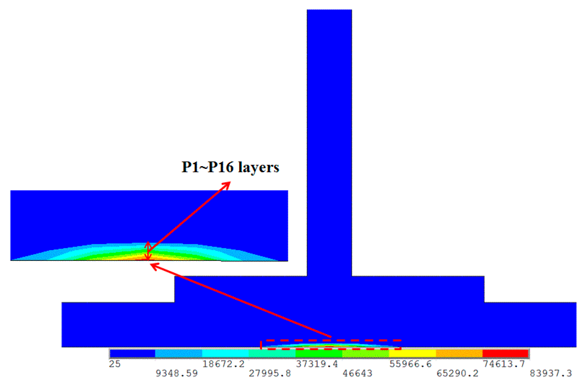
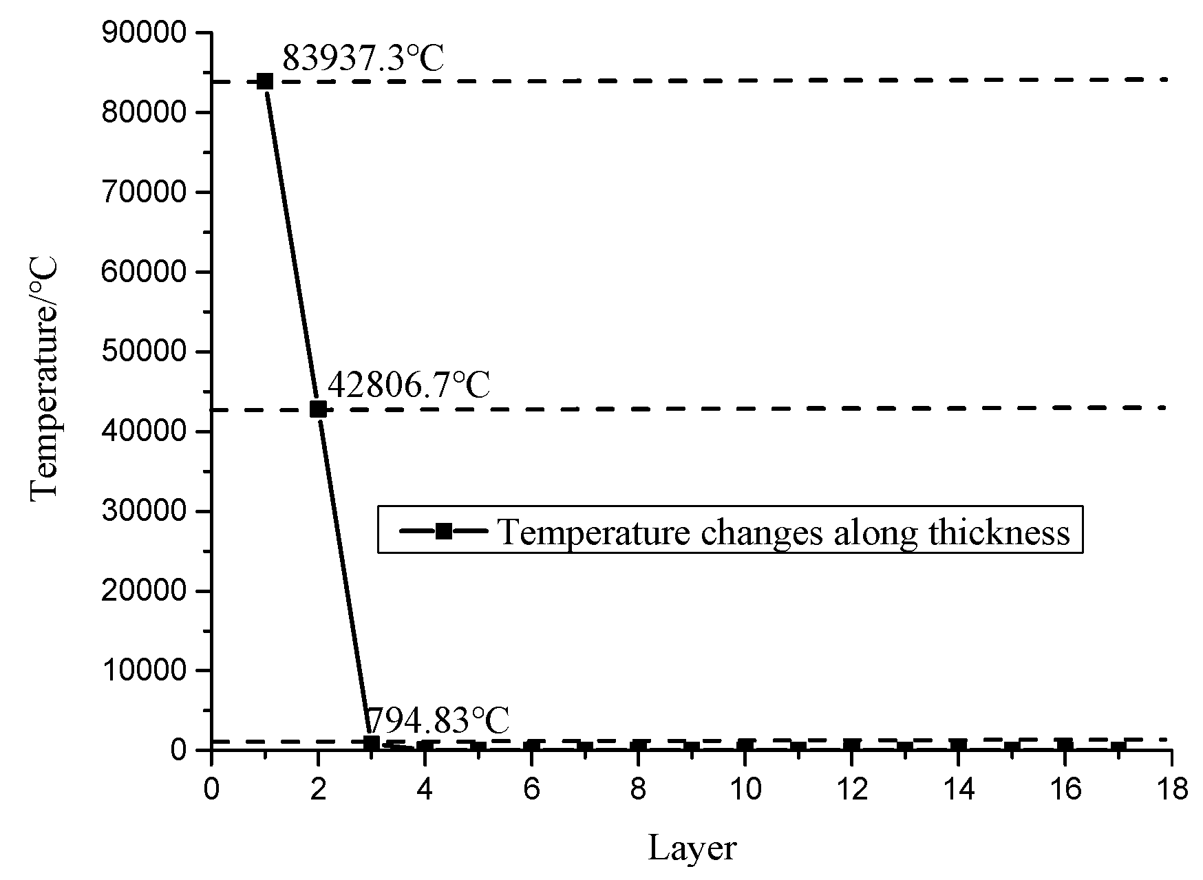
It can be seen from Figure 5 that the temperature profile around the attachment area resembles an ellipse, and the long axis of the ellipse is along fiber direction in P1 layer. The highest temperature is 83937.3 °C, which is much higher than the ablation and sublimation temperatures of carbon fiber. However, the temperature drops sharply along the thickness direction due to the low electric conductivity and thermal conductivity in the thickness direction. Figure 6 presents the temperature distribution in the cross-section and Figure 7 presents the temperature change in the top 17 layers of the benchmark skin. It can be seen from Figure 6 and Figure 7 that the temperatures around the attachment area mainly focus on the top three layers of benchmark skin, with very a small temperature rise in the P4–P16 layers. Temperatures in P16–P24 layers and the T stripper have almost no change. Therefore, it can be concluded that the Joule heat generated by the lightning current mainly causes significant thermal damage in the top three layers around the attachment area, with very little damage in other areas.
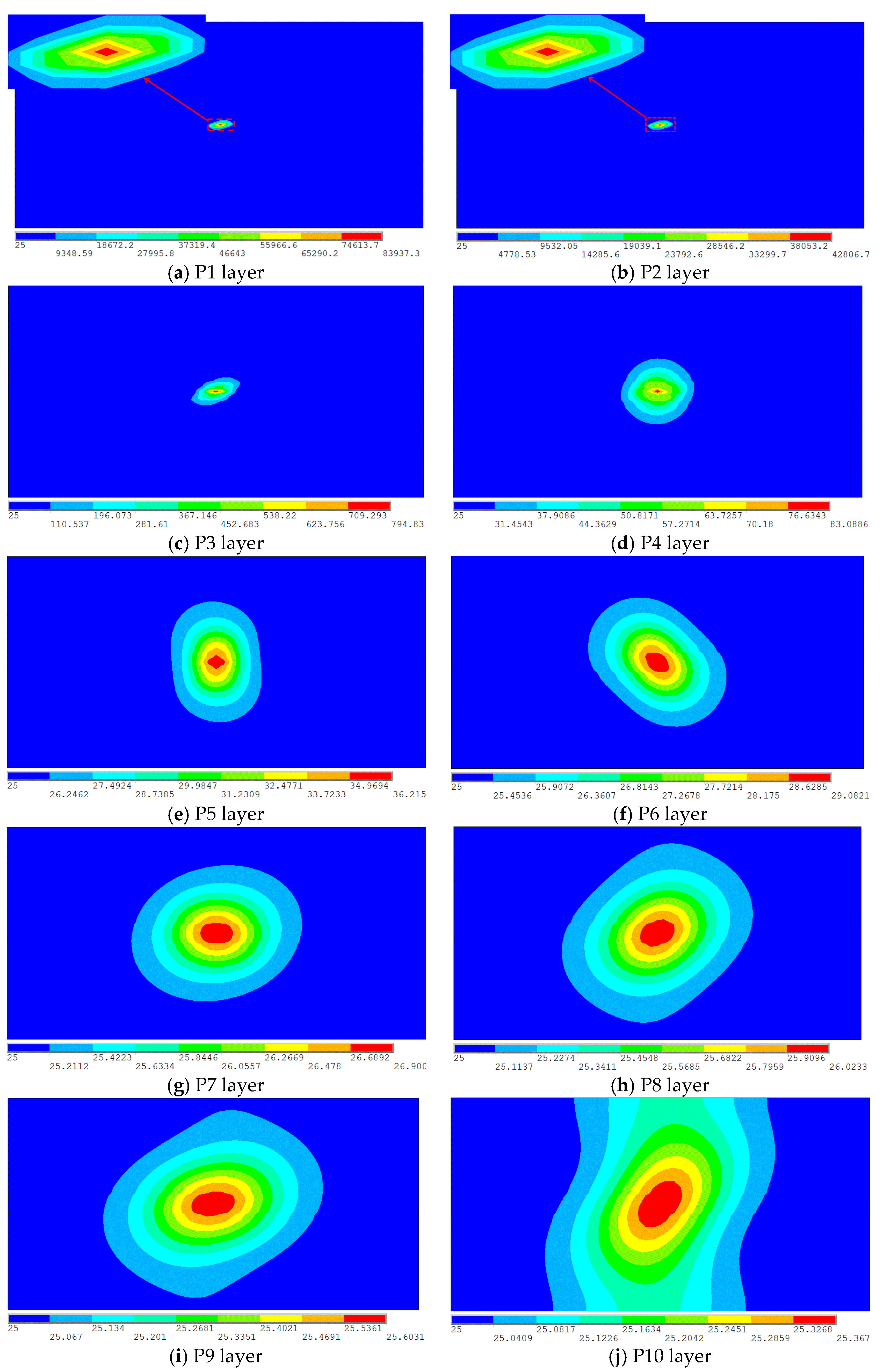
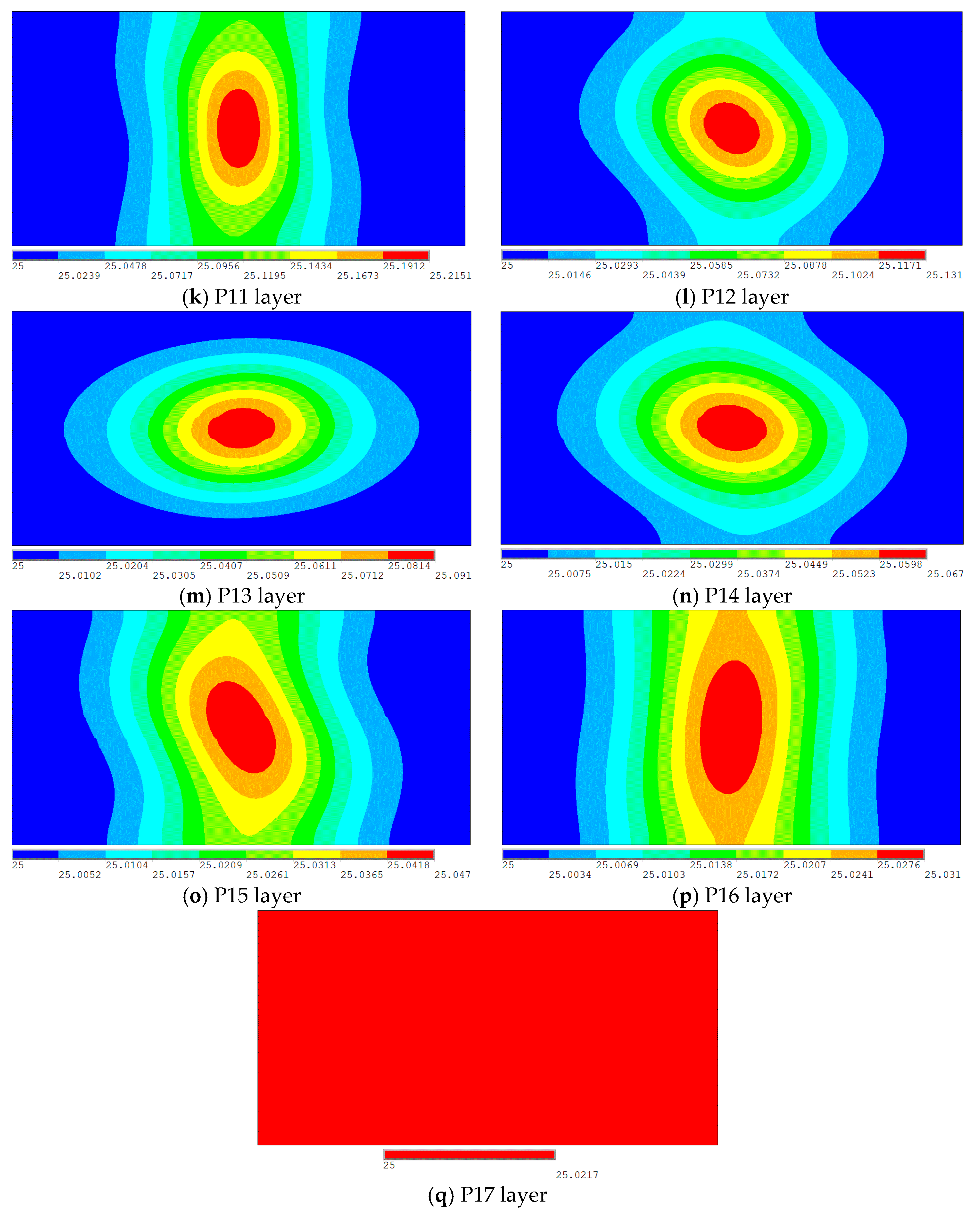
Figure 8 presents the temperature distribution in the top 17 layers of benchmark skin. It can be seen that the closer to the top layer, the higher the temperature will be. The temperature profile in the P1 layer is similar to an ellipse shape and the long axis of the ellipse is roughly along the fiber direction (45°). The influence between each layer is very significant, which can be verified from the temperature contours in P2 layer, P3 layer, P5 layer, P6 layer, and P8 layer. Stacking sequences in these layers are 0°, −45°, −45°, 0°, and 0°, respectively, but the temperature distribution is not along the fiber direction in each layer. These serious effects are mainly caused by the low thermal conductivity in the thickness and transverse direction. The Joule heat effect mainly concentrates on the top three layers of benchmark skin, which is due to the fact that the electric conductivity and thermal conductivity in the thickness direction are much lower than that in the fiber direction. Lightning current mainly conducts along fiber direction in P1 layer, P2 layer, and P3 layer, only a small amount of lightning currents conduct along the thickness direction. The high electric resistance blocks the conduction of lightning current along the thickness direction, which can be confirmed through the temperature distribution in the cross-section, as shown in Figure 6. For example, the highest temperatures in P1 layer and P2 layer are 83,937.3 and 42,806.7 °C, respectively. While the temperature in P3 layer has dropped to 794.83 °C, indicating that only the top two layers will be ablated around the attachment area under this current waveform. The temperature in P4 layer is just 83.0886 °C, which is lower than the molten temperature of resin. Temperatures around the attachment area are between 25 and 37 °C from P5 layer to P17 layer, which is in the range of the environment temperature. Since then, temperatures in inner layers of the benchmark skin as well as the T stripper are not on the rise, agreeing well with Figure 6 and Figure 7. At the same time, although the thermal conductivity in the fiber direction is much greater than that in the other two directions, the difference is far smaller than that of electric conductivity in the fiber direction and the other two directions. Therefore, the influence of thermal conductivity in the thickness direction on the temperature distribution of each layer can almost be ignored, except for the top three layers with high temperature.
3.2. Analysis of the Blow-Off Impulse
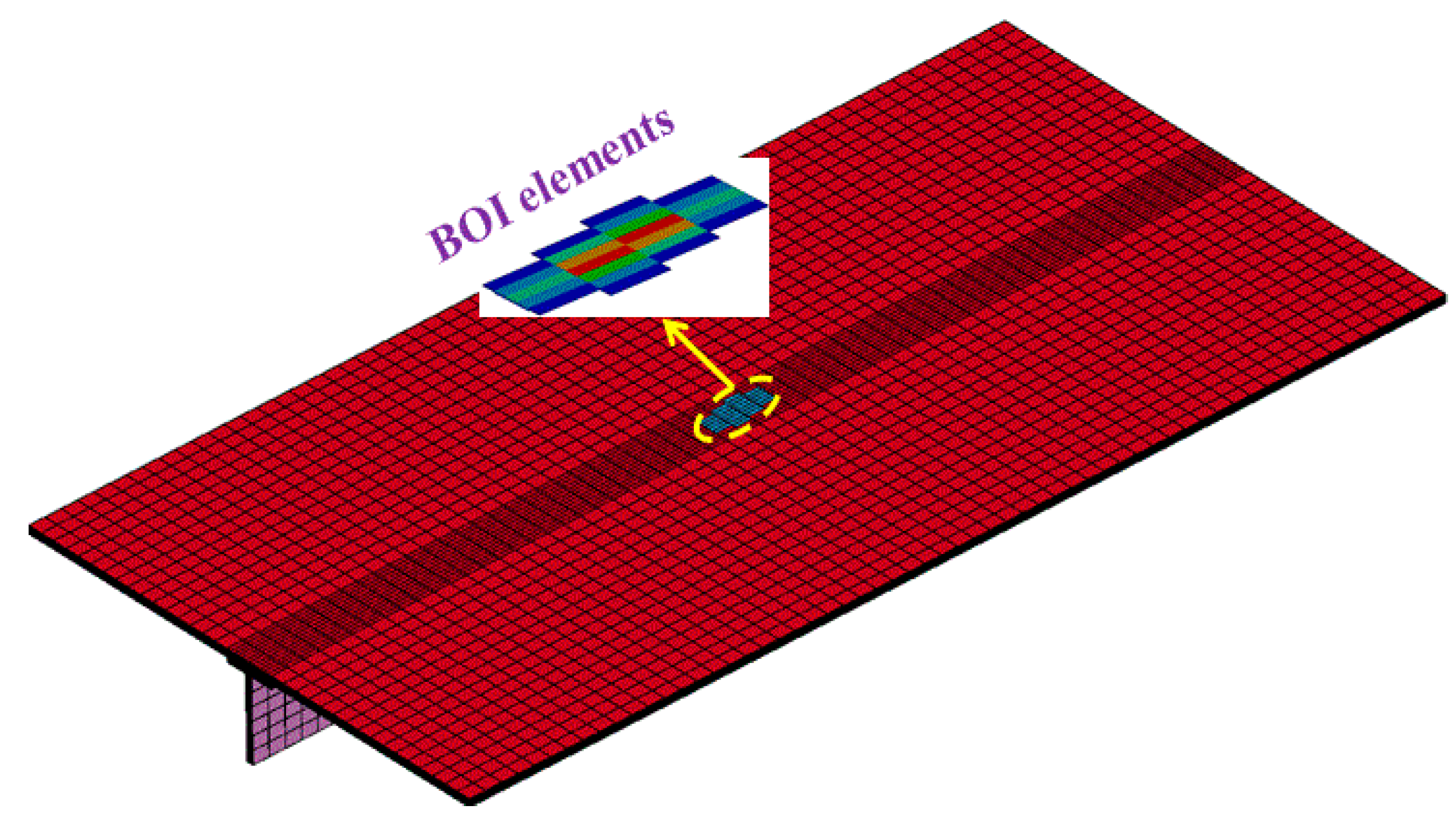
The elements with temperatures exceeding 3316 °C are not defined as failures in the electric-thermal coupling module, but selected as the blow-off impulse elements in the blow-off impulse module. Therefore, element failure is not considered in the electric-thermal coupling module. Figure 9 presents the finite element model of blow-off impulse, it can be seen from Figure 9 that there are 38 blow-off impulse elements in the center area of the composite reinforced panel, while the rest areas are non-blow-off impulse elements. These 38 blow-off impulse elements all concentrate on P1 layer and P2 layer of the benchmark skin. Solution time is 2 μs, the step length factor is set as 0.6, and the output step number is 22. Keyword file is output and submitted to LS-DYNA solver after it is modified in LS-PrePost. Failure elements are defined according to the maximum failure strain. As expressed in Equation (3), yield function can be built through strength parameters and stress tensor of composite materials. Elements will enter the plastic phase when f is greater than zero. Elements will then deform continuously subject to external load and the stiffness of composite materials will be reduced too. The maximum failure strain is defined in the keyword file of ANSYS/LS-DYNA. If the equivalent strains of elements are greater than the maximum failure strain, the elements are defined as failures and will be deleted.
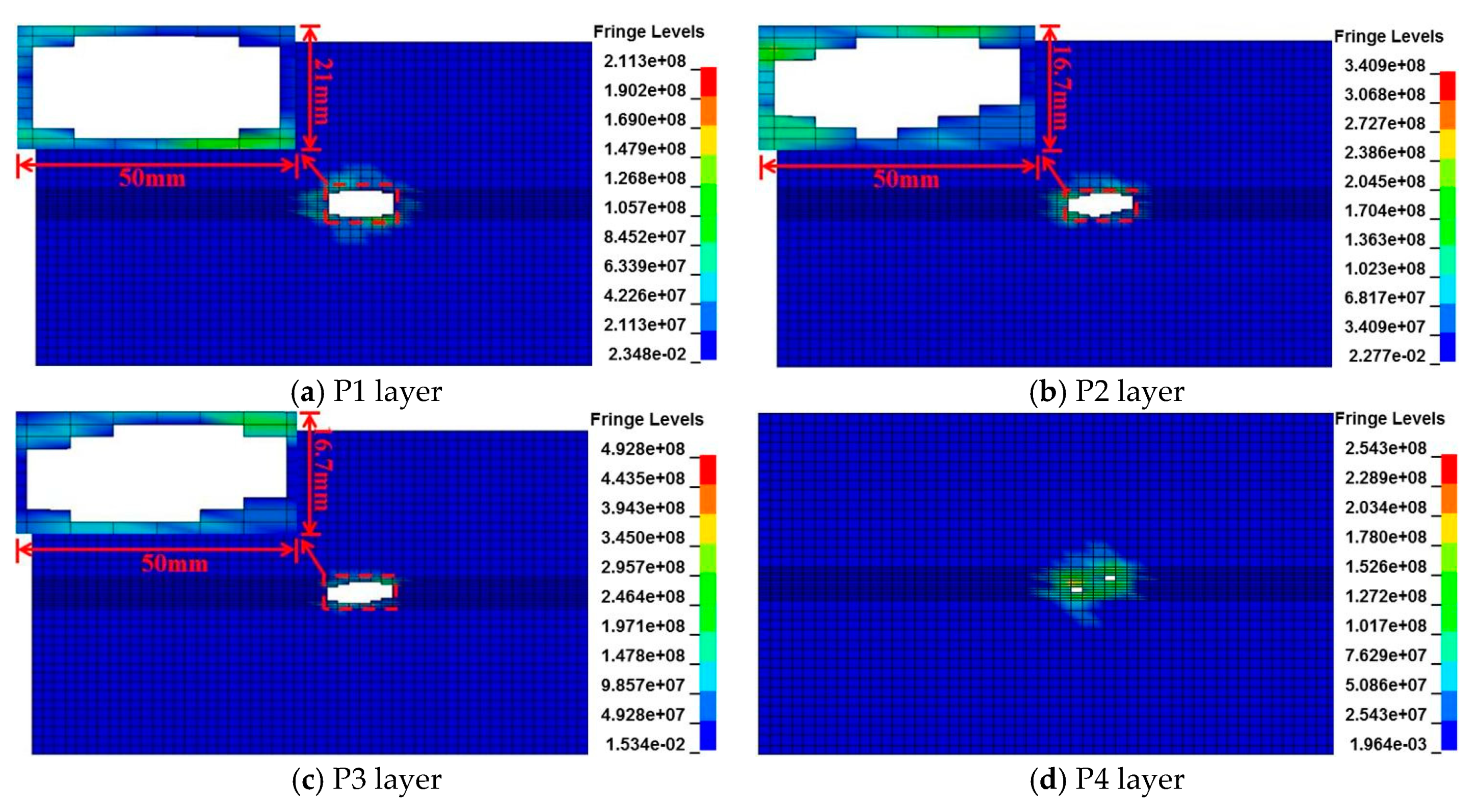
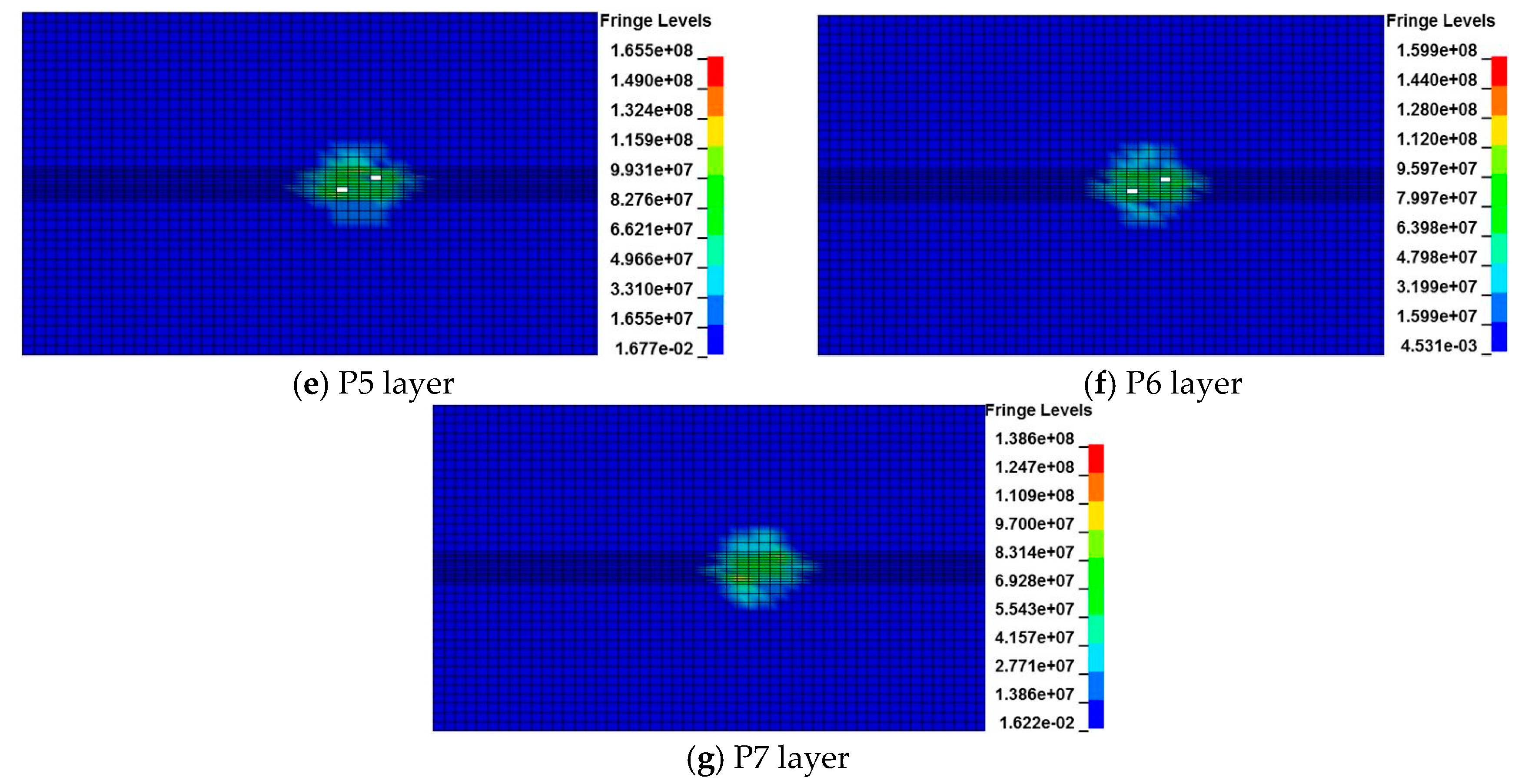
Figure 10 presents the contours of von Mises stress in the top seven layers when the blow-off impulse analysis is completed. It can be seen that the damage caused by blow-off impulse mainly concentrates on the center areas of each layer, and the element deletion phenomenon only appears in the top six layers of the benchmark skin. P1 layer is the most seriously damaged, with 38 elements deleted and size of the failure area is about 50 × 21 mm. However, the contours of von Mises stress is not along 45° in P1 layer but deviates from the fiber direction. In P2 layer and P3 layer, 27 and 40 elements are removed, respectively. The sizes of the failure areas in these two layers are almost the same. There are four elements deleted in P4 layer, P5 layer, and P6 layer, respectively, and no elements deleted after P7 layer. However, there is a large stress concentration phenomenon in the center area of P7 layer. Additionally, the influence on stress distribution between each layer is very significant. For example, stacking sequences of P2 layer and P3 layer are 0° and −45°, respectively, but the contours of von Mises stress are not along the fiber direction in each layer. It can be concluded that the damage forms caused by the blow-off impulse effect alter the initial damage distribution caused by the electric-thermal coupling effect, which makes the damage distribution t deviate from the initial fiber direction.
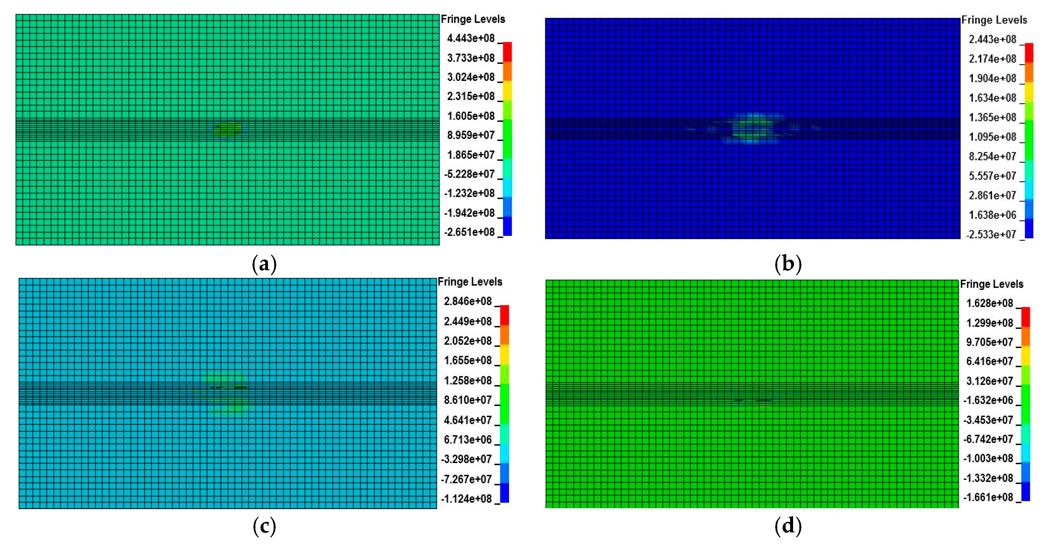
Figure 11 presents the pressure contours of the composite reinforced panel in several typical moments. It can be seen that the implosion effect starts to appear when time is equal to 0.099 µs and great pressure is formed immediately. The maximum pressure is 4.443 × 10⁸ N, but no elements are deleted at this moment. The element deletion phenomenon starts to appear on the top three layers when time is equal to 0.4 µs. Six layers exhibit element deletion phenomenon when time is equal to 1.5 µs, and an obvious concave pit is formed around the blow-off impulse area. But the pressure is not as large as when the implosion effect starts, the maximum pressure is 2.846 × 10⁸ N at this moment. The blow-off impulse effect is completed when time is equal to 2 µs, and the maximum damage is reached at this point. A large concave pit is formed around the blow-off impulse area and the depth of the concave pit is about 1.088 mm, as shown in Figure 12. Additionally, it also can be seen from Figure 12 that the element deletion phenomenon also occurs in the T stripper under the action of the blow-off impulse, indicating that the shock wave may cause some inner damage that cannot be seen on the surface. The element bulge phenomenon appears around the edges of element failure and the bottom of the concave pit is uneven. It can be concluded that the blow-off impulse effect not only causes external damage in the benchmark skin but also causes internal damage in the T stripper.
Figure 13 presents the pressure contours in blow-off impulse elements at the beginning, middle, and end of the calculation, respectively. Figure 14 presents the pressure change of blow-off impulse elements at different moments. It can be seen from Figure 13 and Figure 14 that the pressure increases sharply when the explosion begins and the maximum pressure is 4.181 × 10⁹ N. The pressure then decreases sharply and the decrease-rate becomes slow and eventually tends to balance. However, the volume of blow-off impulse elements expands rapidly in the process of the explosion, then the volume reaches the maximum when the blow-off impulse analysis is completed, which can reflect the bulge phenomenon around the attachment area of lightning strike.
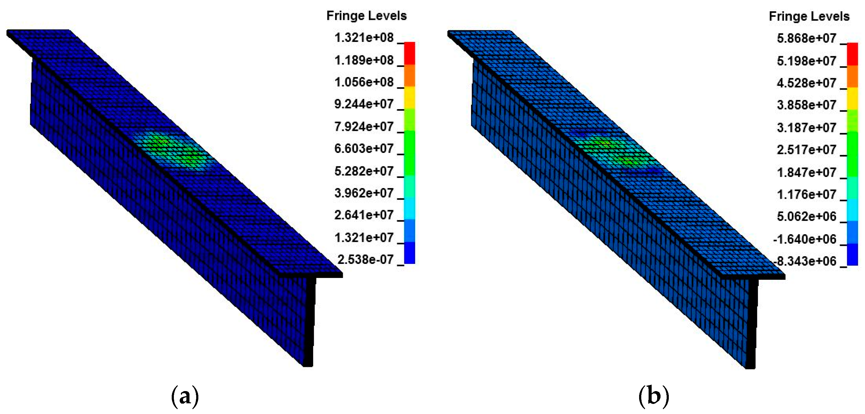
Figure 15 presents the overall pressure contours of the composite reinforced panel after the blow-off impulse analysis is completed. It can be seen that an obvious bulge phenomenon appears around the blow-off impulse area, and the element failure mode around the blow-off impulse area is similar to that around the attachment area of lightning strike. Therefore, the blow-off impulse effect can reflect the damage forms of the composite reinforced panel induced by lightning strike and should be considered. Additionally, the pressure around the blow-off impulse area presents as isotropic rather than anisotropic, which agrees well with the fact that the mechanical properties of composite materials present as anisotropic in low pressure and isotropic in high pressure [25,26]. Figure 16 presents the von Mises stress and pressure in the T stripper. It can be seen that there is no element deletion on the surface of the T stripper, but some internal elements are deleted as shown in Figure 12. This indicates that the blow-off impulse effect has a serious influence on the center areas in the top six layers of the benchmark skin, while the influences on the T stripper and other areas are relatively less serious.
Mesh quality and element dimensions have a great influence on the calculation results. In order to study the influence of mesh quality on calculation results, the damage degree of a composite reinforced panel with five kinds of element dimensions are compared. Calculation results for different element dimensions are given in Table 8. It can be seen that the error will increase with the increase of element dimensions. Although failure area errors change greatly with the increase of the element dimension, damage depth errors change little. However, there will be no blow-off impulse elements around the attachment area if the element dimension is larger than 10.0mm in length direction. Therefore, the element dimension should be as small as possible to enable better calculation results.
4. Conclusions
Based on the anti-lightning strike background of composite materials widely used in aircraft structure design, the thermal explosion phenomenon of composite materials is rarely studied. The blow-off impulse effect of a composite reinforced panel induced by lightning strike is studied through numerical simulation in this paper. A method integrating electric-thermal coupling with an explicit dynamic is proposed in order to study the blow-off impulse effect of a composite reinforced panel. The damage mechanism of a composite reinforced panel caused by the blow-off impulse effect is discussed. The conclusions can be summarized as follows:
- The blow-off impulse effect alters the damage distribution caused by the electric-thermal coupling effect, which makes the damage distribution deviate from the initial fiber direction in each layer.
- The blow-off impulse effect could well present the internal damage, concave pit, and bulge phenomenon around the attachment area of lightning strike, and the failure modes in the blow-off impulse area are similar to the damage forms caused by lightning strike.
- Pressure increases sharply when explosion begins, and then decreases gradually with the increase of time and tends to balance in the end. The pressure of composite materials is not presented as anisotropic but isotropic, agreeing well with the observed characteristic that mechanical behavior of composite materials exhibits anisotropic in low pressure while isotropic in high pressure.
The results obtained in this study can reflect the dynamical damage behavior of composite materials induced by lightning strike to some extent. However, phase transition and delamination are other important damage modes of composite materials, which have not been involved in this study. Therefore, this field needs to be further considered in future investigations.
Author Contributions
Data curation, S.J. and W.H.; formal analysis, S.J., F.W., W.H. and B.X.; methodology, S.J., F.W. and B.X.; writing—original draft, S.J. and F.W.
Funding
This research was funded by the National Natural Science Foundation of China, grant number: 51875463 & 51475369, the Natural Science Basic Research Plan in Shaanxi Province of China, grant number: 2018JM1001.
Acknowledgments
This study is supported by the National Natural Science Foundation of China (No.: 51875463 & No.: 51475369), the Natural Science Basic Research Plan in Shaanxi Province of China (No.: 2018JM1001).
Conflicts of Interest
The authors declare no conflict of interest.
References
- Katunin, A.; Krukiewicz, K.; Turczyn, R.; Sul, P.; Lasica, A. Synthesis and characterization of the electrically conductive polymeric composite for lightning strike protection of aircraft structures. Compos. Struct. 2017, 159, 773–783. [Google Scholar]
- Liu, Z.Q.; Yue, Z.F.; Wang, F.S.; Ji, Y.Y. Combining analysis of coupled electrical-thermal and Blow-off impulse effects on composite laminate induced by lightning strike. Appl. Compos. Mater. 2015, 22, 189–207. [Google Scholar] [CrossRef]
- Hirano, Y.; Katsumata, S.; Iwahori, Y.; Todoroki, A. Artificial lightning testing on graphite/epoxy composite laminate. Compos. Part A Appl. Sci. Manuf. 2010, 41, 1461–1470. [Google Scholar] [CrossRef]
- Deierling, P.E.; Zhupanska, O.I. Experimental study of high electric current effects in carbon/epoxy composites. Compos. Sci. Technol. 2011, 71, 1659–1664. [Google Scholar] [CrossRef]
- Feraboli, P.; Minller, M. Damage resistance and tolerance of carbon/epoxy composite coupons subjected to simulated lightning strike. Compos. Part A Appl. Sci. Manuf. 2009, 40, 954–967. [Google Scholar]
- Kawakami, H.; Feraboli, P. Lightning strike damage resistance and tolerance of scarf-repaired mesh-protected carbon fiber composites. Compos. Part A Appl. Sci. Manuf. 2011, 42, 1247–1262. [Google Scholar]
- Dong, Q.; Guo, Y.L.; Sun, X.C.; Jia, Y.X. Coupled electrical-thermal-pyrolytic analysis of carbon fiber/epoxy composites subjected to lightning strike. Polymer 2015, 56, 385–394. [Google Scholar] [CrossRef]
- Dong, Q.; Guo, Y.L.; Chen, J.L.; Yao, X.L.; Yi, X.S.; Ping, L.; Jia, Y.X. Influencing factor analysis based on electrical-thermal-pyrolytic simulation of carbon fiber composites lightning damage. Compos. Struct. 2016, 140, 1–10. [Google Scholar] [CrossRef]
- Li, S.L.; Yin, J.J.; Yao, X.L.; Chang, F. Damage analysis for carbon fiber/epoxy composite exposed to simulated lightning current. J. Reinf. Plast. Compos. 2016, 35, 1201–1213. [Google Scholar]
- Yin, J.J.; Li, S.L.; Yao, X.L.; Chang, F. Lightning strike ablation damage characteristic analysis for carbon fiber/epoxy composite laminate with fastener. Appl. Compos. Mater. 2016, 23, 821–837. [Google Scholar]
- Ogasawara, T.; Hirano, Y.; Yoshimura, A. Coupled thermal-electrical analysis for carbon fiber/epoxy composites exposed to simulated lighting current. Compos. Part A Appl. Sci. Manuf. 2010, 41, 973–983. [Google Scholar] [CrossRef]
- Abdelal, G.; Murphy, A. Nonlinear numerical modeling of lightning strike effect on composite panels with temperature dependent material properties. Compos. Struct. 2014, 109, 268–278. [Google Scholar] [CrossRef]
- Naghipour, P.; Pineda, E.J.; Arnold, S.M. Simulation of lightning-induced delamination in un-protected CFRP laminates. Appl. Compos. Mater. 2016, 23, 523–535. [Google Scholar] [CrossRef]
- Wang, F.S.; Ji, Y.Y.; Yu, X.S.; Chen, H.; Yue, Z.F. Ablation damage assessment of aircraft carbon fiber/epoxy composite and its protection structures suffered from lightning strike. Compos. Struct. 2016, 145, 226–241. [Google Scholar] [CrossRef]
- Wang, F.S.; Ding, N.; Liu, Z.Q.; Ji, Y.Y.; Yue, Z.F. Ablation damage characteristic and residual strength prediction of carbon fiber/epoxy composite suffered from lightning strike. Compos. Struct. 2014, 117, 222–233. [Google Scholar] [CrossRef]
- Wang, F.S.; Yu, X.S.; Jia, S.Q.; Li, P. Experimental and numerical study on the residual strength of carbon/epoxy composite after lightning strike. Aerosp. Sci. Technol. 2018, 75, 304–314. [Google Scholar] [CrossRef]
- Gagné, M.; Therriault, D. Lightning strike protection of composites. Prog. Aerosp. Sci. 2014, 64, 1–16. [Google Scholar] [CrossRef]
- Wang, B.; Duan, Y.G.; Xin, Z.B.; Yao, X.L.; Abliz, D.; Ziegmann, G. Fabrication of an enriched graphene surface protection of carbon fiber/epoxy composites for lightning strike via a percolating-assisted resin film infusion method. Compos. Sci. Technol. 2018, 158, 51–60. [Google Scholar] [CrossRef]
- Dhanya, T.M.; Chandra, S.Y. Lightning strike effect on carbon fiber reinforced composites-effect of copper mesh protection. Mater. Today. Commun. 2018, 16, 124–134. [Google Scholar] [CrossRef]
- Soulas, F.; Espinosa, C.; Lachaud, F.; Guinard, S. A method to replace lightning strike tests by ball impacts in the design process of lightweight composite aircraft panels. Int. J. Impact. Eng. 2018, 11, 165–176. [Google Scholar] [CrossRef]
- Vipin, K.; Tomohiro, Y.; Takao, O.; Hirano, Y.; Goto, T.; Takahashi, T.; Hassen, A.A.; Ogasawara, T. Polyaniline-based all-polymeric adhesive layer: An effective lightning strike protection technology for high residual mechanical strength of CFRPs. Compos. Sci. Technol. 2019, 172, 49–57. [Google Scholar]
- Zhang, K.; Tang, W.H.; Fu, K.K. Modeling of dynamic behavior of carbon fiber-reinforced polymer (CFRP) composite under X-ray radiation. Materials 2018, 11, 143. [Google Scholar] [CrossRef]
- Tang, W.H.; Wang, D.R.; Huang, X. The sublimation energy versus temperature and pressure and its influence on Blow-off Impulse. Int. Conf. Appl. Math. Mech. Phys. 2011, 5, 1492–1495. [Google Scholar]
- Chen, H.; Tang, W.H.; She, J.H.; Ran, X.W.; Xu, Z.H. The PUFF equation of state parameters for synthetic rubber. Mech. Mater. 2011, 43, 69–74. [Google Scholar] [CrossRef]
- Huang, X.; Tang, W.H.; Jiang, B.H.; Guo, X. The numerical simulation of 2-D thermal shock wave induced by X-Ray in anisotropic material. Chin. J. High. Pres. Phys. 2011, 1, 41–47. (In Chinese) [Google Scholar]
- Huang, X.; Tang, W.H.; Jiang, B.H.; Ran, X.W. Anisotropic constitutive model and its application in simulation of thermal shock wave propagation for cylinder shell composite. Int. Conf. Appl. Math. Mech. Phys. 2011, 9, 1823–1828. [Google Scholar]
- Abry, J.C.; Bochard, S.; Chateauminois, A.; Salvia, M.; Giraud, G. In situ detection of damage in CFRP laminates by electrical resistance measurements. Compos. Sci. Technol. 1999, 59, 925–935. [Google Scholar] [CrossRef]
- Lago, F.; Gonzalez, J.J.; Freton, P.; Uhlig, F.; Piau, G. A numerical modeling of an electric arc and its interaction with the anode: part III. Application to the interaction of a lightning strike and an aircraft in flight. J. Phys. D Appl. Phys. 2006, 39, 2294–2310. [Google Scholar] [CrossRef]
- Chen, J.K.; Sun, C.T.; Chang, C.I. Failure analysis of a graphite/epoxy laminate subjected to combined thermal and mechanical loading. J. Compos. Mater. 1985, 19, 408–423. [Google Scholar] [CrossRef]
- Zaman, W.; Li, K.Z.; Ikram, S.; Li, W.; Zhang, D.S.; Guo, L.J. Morphology, thermal response and anti-ablation performance of 3D-four directional pitch-based carbon/carbon composites. Corros. Sci. 2012, 61, 134–142. [Google Scholar] [CrossRef]
- Aircraft Lightning Environment and Related Test Waveforms; Aerospace Recommended Practice ARP 5412; SAE: Warrendale, PA, USA; Troy, MI, USA, 2005.
Figure 1.
Cross-section of the composite reinforced panel.

Figure 2.
Finite element model and boundary conditions of the composite reinforced panel. (a) Boundary conditions in benchmark skin; (b) boundary conditions in the T stripper.
Figure 2.
Finite element model and boundary conditions of the composite reinforced panel. (a) Boundary conditions in benchmark skin; (b) boundary conditions in the T stripper.

Figure 3.
Double exponential impulse current waveform. (a) Relationship of t1/t2; (b) waveform of 2.6/10.5 μs-0 kA.
Figure 3.
Double exponential impulse current waveform. (a) Relationship of t1/t2; (b) waveform of 2.6/10.5 μs-0 kA.

Figure 4.
Calculation process of blow-off impulse analysis.

Figure 5.
Temperature distribution around the attachment area of the composite reinforced panel. (Unit: °C).
Figure 5.
Temperature distribution around the attachment area of the composite reinforced panel. (Unit: °C).

Figure 6.
Temperature distribution in the cross-section of the composite reinforced panel. (Unit: °C).
Figure 6.
Temperature distribution in the cross-section of the composite reinforced panel. (Unit: °C).

Figure 7.
Temperature change along the thickness direction.

Figure 8.
Temperature distribution of the top 17 layers in the benchmark skin of the composite reinforced panel. (Unit: °C).
Figure 8.
Temperature distribution of the top 17 layers in the benchmark skin of the composite reinforced panel. (Unit: °C).


Figure 9.
Finite element model of the blow-off impulse of the composite reinforced panel.

Figure 10.
Contours of von Mises stress on the top seven layers of the benchmark skin.


Figure 11.
Pressure contours in several typical moments. (a) t = 0.099 µs; (b) t = 0.4 µs; (c) t = 1.5 µs; (d) t = 2 µs.
Figure 11.
Pressure contours in several typical moments. (a) t = 0.099 µs; (b) t = 0.4 µs; (c) t = 1.5 µs; (d) t = 2 µs.

Figure 12.
Damage forms in the cross-section of the composite reinforced panel.

Figure 13.
Pressure contours in blow-off impulse elements. (a) t = 0.0096 µs; (b) t = 1 µs; (c) t = 2 µs.
Figure 13.
Pressure contours in blow-off impulse elements. (a) t = 0.0096 µs; (b) t = 1 µs; (c) t = 2 µs.

Figure 14.
Pressure change of blow-off impulse elements.

Figure 15.
Overall pressure contours of the composite reinforced panel.

Figure 16.
Contours of von Mises and pressure in the T stripper. (a) Contours of von Mises stress; (b) pressure contours.
Figure 16.
Contours of von Mises and pressure in the T stripper. (a) Contours of von Mises stress; (b) pressure contours.


Table 1.
Mechanical properties of IM600/133 composite material.
| Temperature/°C | Ex/GPa | Ey/GPa | Ez/GPa | μxy | μyz | μxz | Gxy/GPa | Gyz/GPa | Gxz/GPa |
|---|---|---|---|---|---|---|---|---|---|
| 25 | 137 | 8.2 | 8.2 | 0.02 | 0.34 | 0.02 | 4.36 | 3 | 4.36 |
| 200 | 137 | 6.56 | 6.56 | 3.488 | 2.4 | 3.488 | |||
| 260 | 137 | 0.082 | 0.082 | 0.03488 | 0.024 | 0.03488 | |||
| 600 | 137 | 0.0041 | 0.0041 | 0.001744 | 0.0012 | 0.001744 | |||
| 3316 | 137 | 0.0041 | 0.0041 | 0.001744 | 0.0012 | 0.001744 |
| Temperature/°C | Electric Resistances/Ω·m | ||
|---|---|---|---|
| Longitudinal | Transverse | Thickness | |
| 27 | 6.224 × 10⁻⁵ | 0.3558 | |
| 127 | 5.948 × 10⁻⁵ | 0.3362 | |
| 227 | 5.676 × 10⁻⁵ | 0.3195 | |
| 327 | 5.429 × 10⁻⁵ | 0.3043 | |
| 427 | 5.2 × 10⁻⁵ | 0.2906 | |
| 457 | 5.139 × 10⁻⁵ | 0.0547 | |
| 527 | 4.994 × 10⁻⁵ | ||
| 627 | 4.801 × 10⁻⁵ | ||
| 727 | 4.627 × 10⁻⁵ | ||
| 827 | 4.459 × 10⁻⁵ | ||
| 3316 | 13.442 × 10⁻⁵ | ||
Table 3.
Thermal expansion coefficients of IM600/133 composite material.
| Temperature/℃ | Thermal Expansion Coefficients/°C−1 | ||
|---|---|---|---|
| Longitudinal | Transverse | Thickness | |
| 25 | 1.8 × 10⁻⁸ | 2.16 × 10⁻⁵ | |
| 200 | 5.4 × 10⁻⁸ | 3.78 × 10⁻⁵ | |
| 260 | 5.4 × 10⁻⁸ | 3.78 × 10⁻⁵ | |
| 600 | 5.4 × 10⁻⁸ | 3.78 × 10⁻⁵ | |
| 3316 | 5.4 × 10⁻⁸ | 3.78 × 10⁻⁵ | |
| 3317 | 5.4 × 10⁻⁸ | 3.78 × 10⁻⁵ | |
| Temperature/°C | Thermal Conductivity/W·m−1·°C−1 | Specific Heat/J·kg−1·°C−1 | Density/kg/m3 | ||
|---|---|---|---|---|---|
| Longitudinal | Transverse | Thickness | |||
| 25 | 11.8 | 0.609 | 1065 | 1520 | |
| 330 | 6.02 | 0.31 | 2050 | ||
| 360 | 5.46 | 0.28 | 4250 | ||
| 500 | 2.8 | 0.14 | 4200 | 1170 | |
| 525 | 2.33 | 0.12 | 1800 | ||
| 815 | 1.4 | 0.072 | 1850 | ||
| 3316 | 1.4 | 0.072 | 2300 | ||
Table 5.
Stacking sequences in each component of the composite reinforced panel.
| Benchmark Skin | Angle/° | Left Side of T Stripper | Right Side of T Stripper | Bottom of T Stripper | Angle/° | |||
|---|---|---|---|---|---|---|---|---|
| Layer | Angle/° | Layer | Angle/° | |||||
| P1 | P24 | 45 | P25 | 45 | P37 | −45 | P49 | 45 |
| P2 | P23 | 0 | P26 | 0 | P38 | 0 | P50 | 0 |
| P3 | P22 | −45 | P27 | −45 | P39 | 45 | ||
| P4 | P21 | 90 | P28 | 0 | P40 | 0 | ||
| P5 | P20 | −45 | P29 | 90 | P41 | 90 | ||
| P6 | P19 | 0 | P30 | 0 | P42 | 0 | ||
| P7 | P18 | 45 | P31 | −45 | P43 | 45 | ||
| P8 | P17 | 0 | P32 | 0 | P44 | 0 | ||
| P9 | P16 | 45 | P33 | 90 | P45 | 90 | ||
| P10 | P15 | 90 | P34 | 0 | P46 | 0 | ||
| P11 | P14 | −45 | P35 | 45 | P47 | −45 | ||
| P12 | P13 | 0 | P36 | 0 | P48 | 0 | ||
Table 6.
The time and current value in each load step of 2.6/10.5 μs-60 kA.
| Load step | 1 | 2 | 3 | 4 | 5 | 6 | 7 | 8 | 9 | 10 | 11 | 12 |
| Time/μs | 1 | 2 | 2.6 | 3 | 7 | 10 | 10.5 | 11 | 15 | 30 | 50 | 80 |
| Load/kA | 46.3 | 58.9 | 60 | 59.5 | 42.6 | 31.5 | 30.3 | 28.5 | 19.1 | 4.2 | 0.57 | 0.028 |
Table 7.
Main parameters of the high-explosive model, JWL EOS, and 59# constitutive model.
| Parameters | ρ/kg/m3 | D/m/s | PCJ/GPa | A/GPa | B/GPa | R1 | R2 | ω | E0/kJ |
| Value | 1520 | 6718 | 18.5 | 540.9 | 9.4 | 4.5 | 1.1 | 0.35 | 8 × 10⁶ |
| Parameters | Xc/MPa | Xt/MPa | Yc/MPa | Yt/MPa | Zc/MPa | Zt/MPa | S12/MPa | S13/MPa | S23/MPa |
| Value | 1281 | 1708 | 192 | 34 | 280 | 52 | 128 | 128 | 96 |
Table 8.
Comparison of calculation results for different element dimensions.
| Serial Number | Element Dimension/mm | Damage Depth/mm | Error | Failure Area/mm2 | Error |
|---|---|---|---|---|---|
| Mesh-1 | 8.33 × 7.0 × 0.15 | 1.088 | - | 1050 | - |
| Mesh-2 | 8.47 × 7.0 × 0.15 | 1.080 | 7.30% | 936 | 10.8% |
| Mesh-3 | 8.62 × 7.0 × 0.15 | 0.962 | 11.58% | 864 | 17.7% |
| Mesh-4 | 8.92 × 7.0 × 0.15 | 0.615 | 43.47% | 670 | 36.2% |
| Mesh-5 | 10.0 × 7.0 × 0.15 | 0.550 | 49.48% | 500 | 52.3% |
© 2019 by the authors. Licensee MDPI, Basel, Switzerland. This article is an open access article distributed under the terms and conditions of the Creative Commons Attribution (CC BY) license (http://creativecommons.org/licenses/by/4.0/).
Share and Cite
MDPI and ACS Style
Jia, S.; Wang, F.; Huang, W.; Xu, B. Research on the Blow-Off Impulse Effect of a Composite Reinforced Panel Subjected to Lightning Strike. Appl. Sci. 2019, 9, 1168. https://doi.org/10.3390/app9061168
AMA Style
Jia S, Wang F, Huang W, Xu B. Research on the Blow-Off Impulse Effect of a Composite Reinforced Panel Subjected to Lightning Strike. Applied Sciences. 2019; 9(6):1168. https://doi.org/10.3390/app9061168
Chicago/Turabian StyleJia, Senqing, Fusheng Wang, Weichao Huang, and Bin Xu. 2019. "Research on the Blow-Off Impulse Effect of a Composite Reinforced Panel Subjected to Lightning Strike" Applied Sciences 9, no. 6: 1168. https://doi.org/10.3390/app9061168
Note that from the first issue of 2016, this journal uses article numbers instead of page numbers. See further details here.