Mechanical Performance of Built-Up Columns Composed of Four Cold-Formed Square Steel Tubes


1
Jiangsu Key Laboratory of Environmental Impact and Structural Safety in Engineering, China University of Mining and Technology, Xuzhou 221116, China
2
Key Laboratory of Deep Geotechnical and Underground Engineering, China University of Mining and Technology, Xuzhou 221116, China
3
Jiangsu Collaborative Innovation Center for Building Energy Saving and Construction Technology, Xuzhou 221116, China
*
Author to whom correspondence should be addressed.
Appl. Sci. 2019, 9(6), 1204; https://doi.org/10.3390/app9061204
Submission received: 15 February 2019
/
Revised: 14 March 2019
/
Accepted: 19 March 2019
/
Published: 21 March 2019
(This article belongs to the Section Civil Engineering)
Abstract
:This study presents an experimental investigation into the mechanical performance of built-up columns composed of four cold-formed square steel tubes under axial load. The four tubes were assembled together with several C-shaped connectors through two self-tapping screws in each junction. The influence of parameters including spacing between tubes, type of connectors and transverse diaphragm were analyzed based on the failure modes, ultimate loads, load-displacement relationships and load-strain relationships measured in the tests. Moreover, a further numerical analysis was carried out to study the effect of the number of connectors, web height of connectors and installing connectors at column ends by means of the verified finite element models. Finally, the numerical results were compared with the strengths predicted by the AISI-S100-2012 code. Results show that the performance of built-up columns can be influenced by the change in the number of connectors and ratio of web height of connectors to spacing between tubes as well as the installation of connectors at column ends. In addition, the current AISI-S100-12 specifications do not provide a good prediction of the built-up columns composed of four cold-formed square steel tubes.
1. Introduction
Galvanized lipped channel sections are mainly used as the bearing components in cold-formed steel (CFS) wall-stud systems, which are confined to low-rise buildings. To apply this system to taller buildings [1,2,3,4], several lipped channel sections are usually combined to form built-up sections. However, the inherent open and thin-walled characteristics of lipped channel sections cause them to suffer from local buckling and distortional buckling. Further, these buckling modes increase the complexity of bearing capacity calculation and greatly cause the decrease of bearing capacity. Therefore, recent research has primarily focused on eliminating the occurrence of such buckling modes and improving the bearing capacity of cold-formed thin-walled built-up sections.
The most common built-up section is the combination of two channels placed back-to-back. Either they were welded together and researched by Dabaon, M. [5,6] and Hosseini Hashemi, B. [7] or connected through self-tapping screws and tested by Stone, T. A. [8] and Lu, Y. [9] Later the channel section is improved at the web stiffened lipped channel section by Anbarasu, M. [10]. In this way, the local buckling of web could be avoided. Maia and Vieira [11] combined two angle steel through battened plates, which are connected to the angles by bolt or welding. EI Aghoury, M. A. [12,13,14] increased the number of angles from two to four to form a box section. In addition, he investigated the effect of the relationship between the slenderness ratio of angles between batten plates and overall slenderness of the column on the compression stability of the built-up section. Similarly, Reyes, W. [15] and Whittle, J. [16] directly welded two C-shaped sections to form a box section and investigated the effect of weld spacing on the stability performance of the box section. However, according to the results obtained in the above literatures, these built-up sections formed by open sections cannot effectively eliminate the occurrence of the local buckling of elements.
Therefore, Liu, X. and Zhou, T. [17] made some improvements on the form of the built-up section, that is, they combined three lipped channel sections into a T-shaped section. The local buckling of elements was effectively eliminated, but the calculation of bearing capacity is still very complicated due to torsional buckling and flexural-torsional buckling. To avoid these defects of the open sections, Aoki, T. and Ji, B. [18] proposed an innovative fabricated column made of steel plates and steel tubes whose sections were closed. The mechanical properties of these sections were also studied in the subsequent literature [19,20,21]. Although their bending and torsional stiffness are improved, the steel plates and steel tubes were connected by welding, which prevented rapid construction. In addition, the hollow flange section [22,23,24] is also proposed to replace the open sections. Kesawan, S. and Mahendran, M. [25] performed an investigation on the structural performance characteristics of intermittently screw/rivet fastened steel hollow flange sections which are structurally efficient compared to the conventional open channel sections. However, the built-up sections can achieve a good mechanical performance unless a very small rivet spacing (<20 mm) was used.
Based on the above literatures, a novel built-up section is proposed, which is formed by four galvanized cold-formed thin-walled square steel tubes assembled through self-tapping screws. However, for the novel section, the great difference from the most frequently used built-up sections (built-up section composed of open channel sections) is that the component is a square tube with a small section size, which is generally 40 mm × 40 mm with a thickness between 0.9–2 mm. These tubes are usually assembled by several connectors, and each joint is generally connected by two self-tapping screws. The cross-sectional height of connectors is preferably not less than the cross-sectional width of tubes. Furthermore, the thickness of the connectors should be the same as that of the tubes. As the novel built-up section is mainly used in the wall and floor in CFS systems, its cross-sectional width is generally between 90–240 mm. However, it is not appropriate to apply the research results of open sections governed by local buckling directly to the novel built-up section. In addition, the study of the multi-tube built-up columns including more than two components is very limited [26]. Most of the widely used multi-tube built-up columns are made of hot rolled steel, whose joints are welded together or bolted with high strength [27]. The instability behaviour of the built-up section made of hot rolled steel connected by welding or bolting is different from that of the built-up section composed of a cold-formed thin-walled square tube assembled through screws. Furthermore, the force on each components of multi-tube columns may not be the same. This structural characteristic determines that the multi-tube built-up column including more than two components is affected more seriously by shear force than a double-chord built-up column. Therefore, it is questionable to apply the research results of a double-chord built-up column directly to a multi-tube built-up column.
This study aims to investigate the mechanical performance of the novel built-up column and to explore some structural parameters that can improve the performance. The performance of the novel built-up columns was firstly experimentally investigated. The failure load, failure deformation, load-displacement curve and load-strain curve were measured. The influence parameters, including spacing between tubes, connectors’ type and transverse diaphragm, were taken into account in tests. Then, a series of numerical models were established and verified by experimental results. The influence of the numbers of connectors, web height of connector and adding connectors at column ends were analyzed by those numerical models. Finally, the numerical results were compared with the North American Specification.
2. Experimental Analysis
2.1. Test Specimens
This test was carried out in the Jiangsu Key Laboratory Environmental Impact and Structural Safety in Engineering. The four tested specimens were made up of four galvanized cold-formed thin-walled square steel tubes with identical length (3000 mm) and cross-sectional dimension (40 mm × 40 mm × 1.5 mm). The detailed structure of these specimens are shown in Figure 1. Those tubes were assembled together by means of batten plates and each junction was connected by two self-tapping screws that conformed to specification. The screw was placed at the trisected point of web height of the batten plate. The connection details are shown in Figure 1. The C-shaped connector (batten plate) with a cross-sectional dimension 40 mm × 10 mm × 1.5 mm was formed by the bending of galvanized cord-formed thin-walled steel sheet. Both ends of specimens were connected with U-shaped tracks through self-tapping screws (ST4.8), which fell into two categories, U150 (150 mm × 60 mm × 1.5 mm) and U240 (240 mm × 60 mm × 1.5 mm).
The nomenclature and dimension of each specimen are listed in Table 1. In this experiment, two sizes of spacing between tubes were designed to investigate their influence on the stability of built-up columns, which were 110 mm and 200 mm respectively. The influence parameter of the connector’s type is studied in such a way that the C-shaped connectors around the column were replaced with a loop formed by the bending of the steel strip. Furthermore, several X-type steel plates (transverse diaphragm) were welded with the four steel tubes to investigate their influence on the performance of the novel built-up section.
2.2. Test Setup and Procedure
The specimens were loaded horizontally by a testing equipment as shown in Figure 2. The specimens were fixed together with the loading frame through the stay bolts and fixed together with the loading plate through bolts. The horizontality of specimens was calibrated by a levelling rod. This loading equipment ensured the axial loading to the maximum extent possible. This was mainly because, the non-axial displacements of cylindrical steel block used to transfer the load were limited by two steel plates with openings. In addition, the cylindrical steel block had a slot along the generatrix, and the bulge at the edge of the openings of two steel plates could just fit into the slot. Therefore, the rotational displacement of the cylindrical steel block was also limited.
As shown in Figure 2, the load was applied by a hydraulic jack of 500 kN capacity and measured by a load cell of 500 kN capacity. The measure devices were shown in Figure 3. Two Linear Variable Displacement Transducer (LVDT) (D1 and D2) were used to measure the axial shortening of the specimens along y-axis. Eight (LVDT) transducers (Dv1–Dv4 and Dh1–Dh4) were placed at the flange and web of four tubes at half the height of the column to measure the lateral displacement. In addition, the lateral displacement along z-axis at quarter and three quarter of the length of the column was measured by the LVDT Dv1/4 and Dv3/4. Sixteen strain gauges (T1-1–T4-4) were pasted on the four sides of the four tubes at mid-height and four strain gauges (B1–B4) were glued at the web of the connectors. A data acquisition system was adopted to record the applied load and readings of the LVDTs and strain gauges. The load increment was 5 kN/5 min until the column buckled. In the post-buckling range, the compression was increased with displacement control in a rate of 0.03 mm/s. Prior to testing, a preload was applied to specimens to make full contact with the loading frame.
2.3. Material Properties
The material properties of tubes, connectors and tracks were measured in this paper. The material grade of tubes, connectors and tracks were Q345 stipulated in GB50018-2002 [28]. All the connectors and U-shaped tracks were fabricated from the same batch of steel sheets. The dimensions of the tensile coupon were conformed to the GB/T 228.1-2010 standard [29]. An electronic universal material testing machine was used to apply load and record readings. An extensometer having a gauge length of 50 mm was attached to each coupon and the corresponding readings were used to determinate the elastic modulus. The relationships between stress and strain of tubes and steel sheets are shown in Figure 4. The measured yield and ultimate stresses are listed in Table 2.
3. Test Results
3.1. Failure Mode
The ultimate loads of the four specimens are listed in Table 3. The deformed shapes at failure of the four specimens were shown in Figure 5. Only one mode of failure was observed in the tests, which was flexural buckling. For the four specimens, lateral deformations at the middle length of the column were visible when the loads were close to the peak. After the loads crossed the peak, the bending deformations increased rapidly. It is worth noting that all the specimens generated lateral displacement on both the x-axis and z-axis. However, the displacement on the x-axis was more pronounced. In addition, after the tubes bended, on the one hand, the end of the tubes was detached from the web of track (Figure 6a), and on the other hand, the angle between C-shaped connector and tube was no longer perpendicular (Figure 6b). The connectors rotated as the tubes bended, which led to the joint of the connector and tube being similar to a hinge point. The rotation of connectors was due to the non-negligible extrusion deformation of the tube plate caused by screws. This indicates that the bending deformation of tubes cannot effectively be avoided by the small web height of connectors and only two screws adopted for connecting connector and tube. Maia and Vieira [11] once concluded that the type of connection is more important than the size of connectors. Therefore, the influence of screws connection should be investigated in future research.
Figure 7 shows the load-strain curves of connectors. It can be seen from Figure 7 that the strain of connectors for S1, S2 and S4 are small and most of them are lower than 25 με. This finding shows that the deformation of connectors are mainly in the form of rigid motion, which indirectly validates the hinge points observed in Figure 6b. As shown in Figure 6c, it can be seen that a fracture occurred at the weld, which connected the X-type transverse diaphragm and tubes (S4). This shows that the X-type transverse diaphragm does play a role in resisting the relative deformation between tubes. However, the transverse diaphragm does not play a role in improving the carrying capacity, for the bearing capacity of S4 is 12.3% lower than that of S1. Figure 6d shows the distortion of the steel strip and pullout of the screws. The steel strip has undergone a large deformation, which can be verified by the large strain values as shown in Figure 7(S3). Although the loop formed by steel strips does not have rigid motion like C-shaped connectors, the steel strip cannot restrain the flexural deformation of tubes well because of the poor bending resistance. Therefore, the bearing capacity of specimen S3 is 15.85% lower than that of S1. The spacing between tubes of S1 and S2 are 200 mm and 110 mm, respectively, with a difference of 2.65% in ultimate bearing capacity, which illustrates that the factor of spacing between tubes has no obvious effect on improving the ultimate load of novel built-up columns.
3.2. Load-Lateral Displacement Curves
The load-lateral displacement relationships for specimen S1 are plotted in Figure 8. Dv1/4 and Dv3/4 represent the displacement at the column quarter-length point along the z-axis (see Figure 3). As can be seen from Figure 8, the deformation of a quarter point near the loading end is different from that of a quarter point far away from the loading end, which means that the deformation of the column is not perfectly symmetric. In addition, Dv1 and Dh3 represent the deformation at the column mid-length point along the z-axis and the x-axis respectively. To further investigate the effect of the transverse diaphragm, the mid-length lateral deformation of S4 and S1 are compared. The displacement of S4 at the ultimate load in the X and Z directions is 20.67 mm and 7.15 mm respectively, and the ratio of them is 2.89, but the displacements of S1 is 23.74 mm and 14.02 mm respectively, and the ratio of them is 1.69. The comparison indicates that the deformation of S4 is closer to one-way bending than that of S1. It is possible that the transverse diaphragms of S4 enhance the torsional resistance of the built-up section. To sum up, the transverse diaphragm could improve the torsional resistance of the built-up section. But it does not work on improving the bearing capacity of the built-up column.
3.3. Load-Strain Curves
For ease of description, the four tubes (T1, T2, T3 and T4) belonging to the same built-up column are numbered. Figure 9 plots the strain of tubes of S1 versus the load. It is specified that the compression strain is negative and the tensile strain is positive. It can be seen that the curves kept growing linearly at the initial stage and the load dropped especially fast after the curve reached the peak point. The tube T1 and T3 kept in compression zone throughout the loading process. The tubes T2 and T4 went into tensile zone in the post-buckling stage. In addition, it can be found that not all the four tubes generated strain at the initial stage of loading. When the load didn’t exceed 20 kN, the value of strain for tubes (except tube T1) was small, which means that the four tubes are not subjected to load at the same time. According to Table 2, the yield stress of the tube is 375 MPa and the Young’s modulus is 204 GPa. Therefore, the yield strain is 1850 με derived from 375 MPa divided by 204 GPa. It can be known from Figure 9 that most of the strain of four tubes are smaller than the yield strain during the whole loading process. Moreover, only a portion of the strain exceeds 1850 με in the post-buckling phase. That is to say, there are very few cross-section areas that went into the plastic zone. The above shows that the four tubes lost stability before the strain of the tubes reached the yield value. The bearing capacity of the steel tube has not been fully utilized during the loading process. Therefore, it is necessary to improve the structure so as to maximize the bearing capacity of the four tubes.
From the above test results and analysis, it can be concluded that changing the spacing between tubes, replacing the C-shaped connectors with loops formed by steel strips and setting the transverse diaphragm have no effect on improving the bearing capacity of built-up columns. Therefore, it is necessary to further study the influence of more factors on the bearing capacity performance of built-up columns by means of the finite element method.
4. Numerical Analysis
4.1. Numerical Models
The tubes, connectors and tracks of built-up columns were modeled by commercial ANSYS software with SHELL181 element, which has four nodes and six degrees of freedom at each node. Since the two ends of the column was not rigidly connected to the web of the tracks, the nodes on the end of tubes and the nodes on the web of the tracks in the vicinity were modelled as contact pairs. The contact segment between tubes and tracks was simulated by element of TARGE 170 and CONTA 175. In addition, the transverse diaphragm was modeled with BEAM188 element. For the screws used in tests, since no damage was found in the test, the self-tapping screw was simulated by coupling the displacement in three directions. The elastic modulus and yield strength of the tubes, connectors and tracks are referred in Table 2. Elastic perfect plastic stress-strain curve complying with isotropic hardening and Von Mises yield criterion was adopted for the material model. In addition, the loading end of the column was restrained against translational and rotational degrees of freedom in both X and Z directions. The other end was restrained against all three translational degrees of freedom and two rotational degrees of freedom in both X and Z directions. The linear load was applied on the node of tubes directly in the finite element models. An initial imperfection in the form of half of a sine wave was introduced into finite element models with an amplitude of 1/1000 of column length [30,31,32]. Residual stresses were not included in the model for it had little effect on the performance of built-up column [33,34]. The arc-length method was used in solving the nonlinear system of equations.
4.2. Validation of Finite Element Model
The numerical models were verified by the test results. The comparison results including ultimate loads, failure shapes and load-axial shortening curve (take S1 as an example) are given in Table 3, Figure 10 and Figure 11. From the Table 3, it can be seen that, the difference between numerical results and test results are within 10%. Moreover, as you can see in Figure 10, both the simulations and experiments exhibit similar failure modes. The ultimate loads and the failure shapes obtained from numerical analysis are in good agreement with those from tests. As for the comparison of load-axial shortening curves, there are some differences in the axial displacement corresponding to the peak value of the curves (see Pu-FEA (couple) in Figure 11a. The difference may be due to the fact that there is a small slip at the screw connection in the tested component, while the slippage of each connection adds up to a considerable axial displacement. Therefore, another numerical model, in which the screw was simulated by the nonlinear spring element Combin39 [35] (Slippage can be considered. The spring stiffness was shown in Figure 11b), was established and compared with the experimental results, as shown in Figure 11a. It can be seen that the curve of Pu-FEA (COMBIN 39) meets the tested curve better. The new established finite element model is used to the in-depth study of the influence of the web height of connector and number of connectors on the bearing character of built-up columns.
4.3. Effect of Web Height of Connector
According to the experiments, the connectors having web height of 40 mm cannot effectively restrain the deformation of tubes, so the web height of the connector becomes a factor to be considered in the numerical analysis. The influence of web height of the connector on the mechanical performance of built-up column was analyzed by means of a dimensionless parameter named as web height/spacing ratio, that is, the ratio of the web height of connector to the spacing between tubes. The models for comparison were established based on S1 and the web height of the connectors was 50 mm, 60 mm, 80 mm and 100 mm respectively, and the corresponding web height/spacing ratios were 0.25, 0.3, 0.4 and 0.5 respectively. The number of screws in each junction were kept at two.
The change of bearing capacity with the web height/spacing ratio is shown in Figure 12. From the figure, we can see that the bearing capacity of the built-up column increased obviously with the increase of web height/spacing ratio. When the web height/spacing ratio is 0.5, the local plastic deformation of tubes was observed during the post-buckling period (see Figure 13). This indicates that with the increase of the web height/spacing ratio, the ability of the connector to restrain the deformation of tubes is improved, and the composed action between tubes is also strengthened. However, when the parameter increases from 0.4 mm to 0.5 mm, the bearing capacity of the built-up column increases only 2.6 %. The increasing range decreases significantly after the parameter is greater than 0.4. This shows that the increase in the web height/spacing ratio does not result in a sustained significant increase in the bearing capacity of the built-up column. Therefore, for the built-up column with length of 3000 mm, the ratio of the web height of connector to the spacing between the tubes is suggested to be 0.4.
4.4. Effect of Number of Connector
To investigate the effect of the number of connectors on the performance of the built-up column, the numerical models with column length ranged from 600–3000 mm were established and each column length had a variable number of connectors, varying from 0–7. An increase in the number of connectors means a decrease in the spacing between connectors. The remaining dimension of these models were consistent with that of the specimen S1, and the details were listed in Table 4. The load-axial shortening curves of models with different number of connectors were compared, as shown in Figure 14. Note that, the number of connectors described here refers to the number of connectors in only one side of the built-up column. From Figure 14, it can be observed that with the increase of the number of connectors, the peak of the curves increases and the ductility of the columns also improves, which shows that increasing the number of connectors can improve the mechanical performance of the built-up column.
Furthermore, the effect of the number of connectors was also analyzed from the aspect of the strength-to-weight (STW) ratio, as listed in Table 4. Note, the strength-to-weight ratio is derived from dividing the ultimate capacity obtained from the numerical calculation by the total weight of the models. As listed in Table 4, for the columns having length of 2400 mm and 3000 mm, when the column length is the same, the STW ratio increases with the increase in the number of connectors. For example, for the column with length of 3000 mm, the ultimate load of the model with 7 connectors is increased by 54% compared with the model without connectors, and the STW ratio is improved by 28%. However, for the columns with length of 600 mm, 1200 mm and 1800 mm, the STW ratio decreases as the number of connectors increases. For example, for the column with length of 1800 mm, the ultimate load of the model with 4 connectors is only increased by 8% compared with the model without connectors, but the STW ratio is reduced by 9%. This shows that the increase in the number of connectors can improve the economic performance of long columns but reduce the economic performance of middle and short columns.
Finally, in order to better improve the mechanical performance of the built-up column from the structure, two additional connectors were mounted at both ends of S1. The results of the model with end connectors were listed in Table 4 as L3000S700-5 (end). It can be observed that the bearing capacity of L3000S700-5 (end) is increased by 14.2% compared to that of L3000S700-3 (S1, same spacing between connectors), but decreased by 3.4% compared to that of L3000S500-5 (same number of connectors). This shows that the performance of the built-up column can be improved by mounting connectors at the column ends without changing the spacing between connectors. However, on the premise of the same number of connectors, it has a more obvious effect on improving the mechanical performance to reduce spacing between connectors than to install connectors at column ends.
5. Comparisons with AISI-S100-12 Code
The strengths of the novel built-up section are evaluated according to the current AISI-S100-12 code [36] of practice. The comparison between numerical results and predictions are shown in Table 4. It is clear that the AISI-S100-12 is conservative for the built-up columns without connectors, and the conservatism increased with the increase of column length. For the columns having connectors, it can be seen that the predictions are unconservative for the built-up columns with length of 3000 mm, 2400 mm and 1800 mm. The ratio of P-FEA/Pu-AISI decreased with the increase of column length. Especially for the columns with a length of 3000 mm, the ratios of P-FEA/Pu-AISI were between 0.58 and 0.84, which were far less than 1. This may be due to the fact that the slenderer the column, the weaker the restraint effect of the connectors, which leads to the poor combination effect between tubes. However, the predictions are conservative for the columns with length of 1200 mm and 600 mm. In addition, the comparisons show that the code does not provide a good prediction, with a mean of 1.11 and a coefficient of variation (COV) of 0.556.
6. Conclusions
The performance of built-up columns composed of four cold-formed steel tubes assembled by several connectors were experimentally and numerically investigated. The conclusions are as follows:
- (1)
- The experimental results showed that the built-up columns composed of four cold-formed thin-walled steel square tubes failed in flexural buckling.
- (2)
- It has no effect on improving the mechanical performance of built-up columns to change spacing between tubes and to replace the C-shaped connectors with loops formed by steel strip as well as to install a transverse diaphragm. However, the performance can obviously be improved by the change of number of connectors and ratio of web height of connectors to spacing between tubes as well as the installation of connectors at column ends. For the built-up column with length of 3000 mm, it is suggested that the web height/spacing ratio should be 0.4.
- (3)
- The increase in the number of connectors can improve the economic performance of longer columns but reduce the economic performance of shorter columns. In addition, the performance of the built-up column can be improved by mounting connectors at the column ends without changing the spacing between connectors. However, on the premise of the same number of connectors, it has a more obvious effect on improving the mechanical performance to reduce spacing between connectors than to install connectors at column ends.
- (4)
- The current AISI-S100-12 code does not provide a good prediction to the novel built-up columns composed of four cold-formed steel tubes.
In further study, the influence of the number of screws connecting the tubes and connectors on the combination action between tubes will be investigated.
Author Contributions
Conceptualization, X.C. and J.X.; software, X.C. and R.M.; validation, X.C. and B.X.; formal analysis, X.C.; investigation, X.C., B.X. and R.M.; Funding acquisition, J.X.; writing—original draft preparation, X.C.; writing—review and editing, X.C. and J.X.
Funding
This research was funded by Fundamental Research Funds for the Central Universities (2018ZDPY04).
Acknowledgments
The authors wish to thank the reviewers for constructive comments and suggestions that have helped to improve our manuscript.
Conflicts of Interest
The authors declare no conflict of interest.
References
- Fiorino, L.; Macillo, V.; Landolfo, R. Shake table tests of a full-scale two-story sheathing-braced cold-formed steel building. Eng. Struct. 2017, 151, 633–647. [Google Scholar] [CrossRef]
- Fiorino, L.; Terracciano, M.T.; Landolfo, R. Experimental investigation of seismic behaviour of low dissipative CFS strap-braced stud walls. J. Constr. Steel Res. 2016, 127, 92–107. [Google Scholar] [CrossRef]
- Accorti, M.; Baldassino, N.; Zandonini, R.; Scavazza, F.; Rogers, C.A. Response of CFS Sheathed Shear Walls. Structures 2016, 7, 100–112. [Google Scholar] [CrossRef]
- Shamim, I.; Rogers, C.A. Steel sheathed/CFS framed shear walls under dynamic loading: Numerical modelling and calibration. Thin Walled Struct. 2013, 71, 57–71. [Google Scholar] [CrossRef]
- Dabaon, M.; Ellobody, E.; Ramzy, K. Experimental investigation of built-up cold-formed steel section battened columns. Thin Walled Struct. 2015, 92, 137–145. [Google Scholar] [CrossRef]
- Dabaon, M.; Ellobody, E.; Ramzy, K. Nonlinear behaviour of built-up cold-formed steel section battened columns. J. Constr. Steel Res. 2015, 110, 16–28. [Google Scholar] [CrossRef]
- Hosseini Hashemi, B.; Jafari, M.A. Evaluation of Ayrton-Perry formula to predict the compressive strength of batten columns. J. Constr. Steel Res. 2012, 68, 89–96. [Google Scholar] [CrossRef]
- Stone, T.A.; LaBoube, R.A. Behavior of cold-formed steel built-up I-sections. Thin Walled Struct. 2005, 43, 1805–1817. [Google Scholar] [CrossRef]
- Lu, Y.; Zhou, T.; Li, W.; Wu, H. Experimental investigation and a novel direct strength method for cold-formed built-up I-section columns. Thin Walled Struct. 2017, 112, 125–139. [Google Scholar] [CrossRef]
- Anbarasu, M.; Kanagarasu, K.; Sukumar, S. Investigation on the behaviour and strength of cold-formed steel web stiffened built-up battened columns. Mater. Struct. 2015, 48, 4029–4038. [Google Scholar] [CrossRef]
- Maia, W.F.; Vieira, L.C.M., Jr.; Schafer, B.W.; Malite, M. Experimental and numerical investigation of cold-formed steel double angle members under compression. J. Constr. Steel Res. 2016, 121, 398–412. [Google Scholar] [CrossRef]
- El Aghoury, M.A.; Salem, A.H.; Hanna, M.T.; Amoush, E.A. Strength of cold formed battened columns subjected to eccentric axial compressive force. J. Constr. Steel Res. 2015, 113, 58–70. [Google Scholar] [CrossRef]
- El Aghoury, M.A.; Salem, A.H.; Hanna, M.T.; Amoush, E.A. Ultimate capacity of battened columns composed of four equal slender angles. Thin Walled Struct. 2013, 63, 175–185. [Google Scholar] [CrossRef]
- El Aghoury, M.A.; Salem, A.H.; Hanna, M.T.; Amoush, E.A. Experimental investigation for the behaviour of battened beam-columns composed of four equal slender angles. Thin Walled Struct. 2010, 48, 669–683. [Google Scholar] [CrossRef]
- Reyes, W.; Guzmán, A. Evaluation of the slenderness ratio in built-up cold-formed box sections. J. Constr. Steel Res. 2011, 67, 929–935. [Google Scholar] [CrossRef]
- Whittle, J.; Ramseyer, C. Buckling capacities of axially loaded, cold-formed, built-up C-channels. Thin Walled Struct. 2009, 47, 190–201. [Google Scholar] [CrossRef]
- Liu, X.; Zhou, T. Research on axial compression behavior of cold-formed triple-lambs built-up open T-section columns. J. Constr. Steel Res. 2017, 134, 102–113. [Google Scholar] [CrossRef]
- Aoki, T.; Ji, B. Experimental Study on Buckling Strength of Tri-Tube Steel Members. In Proceedings of the 3th International Conference on Coupled Instabilities in Metal Structures, Lisbon, Portual, 21–23 September 2000; pp. 283–290. [Google Scholar]
- Heidarpour, A.; Cevro, S.; Song, Q.; Zhao, X. Behaviour of stub columns utilising mild-steel plates and VHS tubes under fire. J. Constr. Steel Res. 2014, 95, 220–229. [Google Scholar] [CrossRef]
- Heidarpour, A.; Cevro, S.; Song, Q.; Zhao, X. Behaviour of innovative stub columns utilising mild-steel plates and stainless steel tubes at ambient and elevated temperatures. Eng. Struct. 2013, 57, 416–427. [Google Scholar] [CrossRef]
- Javidan, F.; Heidarpour, A.; Zhao, X.; Minkkinen, J. Performance of innovative fabricated long hollow columns under axial compression. J. Constr. Steel Res. 2015, 106, 99–109. [Google Scholar] [CrossRef]
- Kesawan, S.; Mahendran, M. Fire design rules for LSF walls made of hollow flange channel sections. Thin Walled Struct. 2016, 107, 300–314. [Google Scholar] [CrossRef]
- Kesawan, S.; Mahendran, M. Predicting the performance of LSF walls made of hollow flange channel sections in fire. Thin Walled Struct. 2016, 98, 111–126. [Google Scholar] [CrossRef]
- Kesawan, S.; Mahendran, M. Thermal performance of load-bearing walls made of cold-formed hollow flange channel sections in fire. Fire Mater. 2015, 40, 704–730. [Google Scholar] [CrossRef]
- Kesawan, S.; Mahendran, M.; Dias, Y.; Zhao, W. Compression tests of built-up cold-formed steel hollow flange sections. Thin Walled Struct. 2017, 116, 180–193. [Google Scholar] [CrossRef]
- Guo, Y.; Wang, J. Instability behavior and application of prismatic multi-tube latticed steel column. J. Constr. Steel Res. 2009, 65, 12–22. [Google Scholar] [CrossRef]
- Guo, Y.; Zhang, B.; Zhao, S.; Dou, C.; Pi, Y. Ultimate Resistance Design of Shuttle-Shaped Steel Tubular Latticed Columns. J. Struct. Eng. 2014, 140, 4014076. [Google Scholar] [CrossRef]
- Technical code of cold-formed thin-wall steel structures. In GB 50018-2002; China Planning Press: Beijing, China, 2002.
- Metallic materials—Tensile testing at ambient temperature. In GB/T 228.1-2010; Standards Press of China: Beijing, China, 2010.
- Bertocci, L.; Comparini, D.; Lavacchini, G.; Orlando, M.; Salvatori, L.; Spinelli, P. Experimental, numerical, and regulatory P-Mx-My domains for cold-formed perforated steel uprights of pallet-racks. Thin Walled Struct. 2017, 119, 151–165. [Google Scholar] [CrossRef]
- Szymczak, C.; Kujawa, M. Buckling of thin-walled columns accounting for initial geometrical imperfections. Int. J. Nonlin. Mech. 2017, 95, 1–9. [Google Scholar] [CrossRef]
- Orlando, M.; Lavacchini, G.; Ortolani, B.; Spinelli, P. Experimental capacity of perforated cold-formed steel open sections under compression and bending. Steel Compos. Struct. 2017, 24, 201–211. [Google Scholar]
- Young, B.; Ellobody, E. Design of cold-formed steel unequal angle compression members. Thin Walled Struct. 2007, 45, 330–338. [Google Scholar] [CrossRef]
- Ellobody, E.; Young, B. Behavior of Cold-Formed Steel Plain Angle Columns. J. Struct. Eng. 2005, 131, 457–466. [Google Scholar] [CrossRef]
- Ye, J.; Feng, R.Q.; Chen, W.; Liu, W. Behavior of cold-formed steel wall stud with sheathing subjected to compression. J. Constr. Steel Res. 2016, 116, 79–91. [Google Scholar] [CrossRef]
- North American specification for the design of cold-formed steel structural members. In AISI-S100-12; American Iron and Steel Institute: Washington, DC, USA, 2012.
Figure 1.
Configurations of specimens (unit: mm).

Figure 2.
Loading devices.
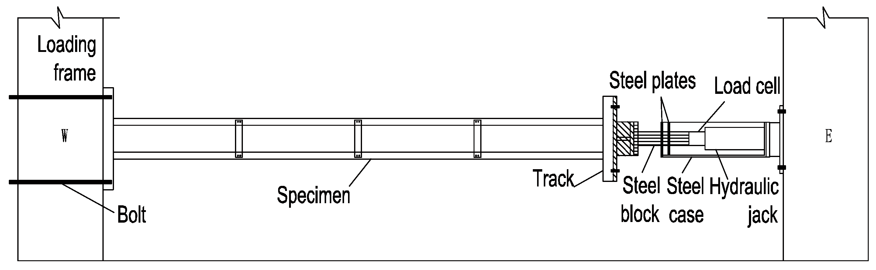
Figure 3.
Measuring devices.

Figure 4.
Stress–strain curves: (a) Tube; (b) Steel plate (connector and track).
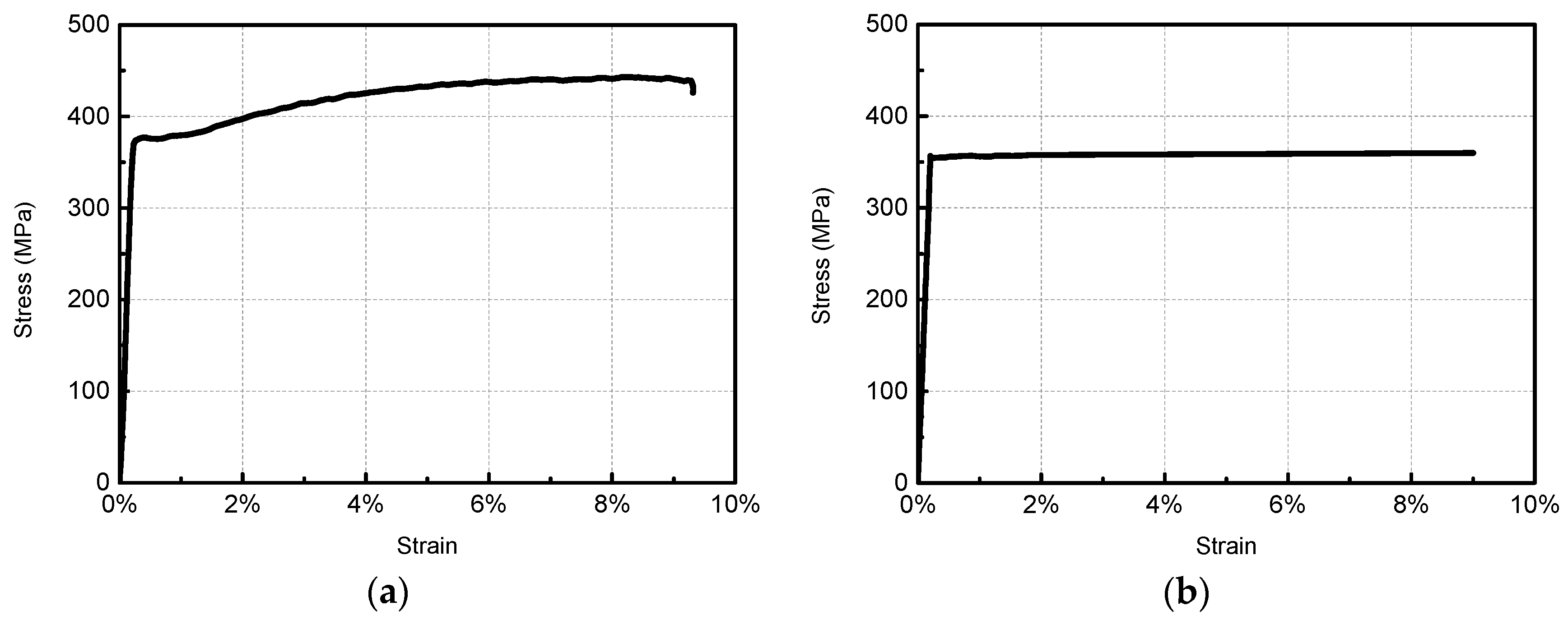
Figure 5.
Deformed shapes at failure: (a) S1; (b) S2; (c) S3; (d) S4.

Figure 6.
Detailed deformed shapes of specimens: (a) Separation of tubes and track; (b) Rotation of connectors with the bending deformation of tubes; (c) Crack of welding seam; (d) Distortion of steel strip and pullout of the screws.
Figure 6.
Detailed deformed shapes of specimens: (a) Separation of tubes and track; (b) Rotation of connectors with the bending deformation of tubes; (c) Crack of welding seam; (d) Distortion of steel strip and pullout of the screws.
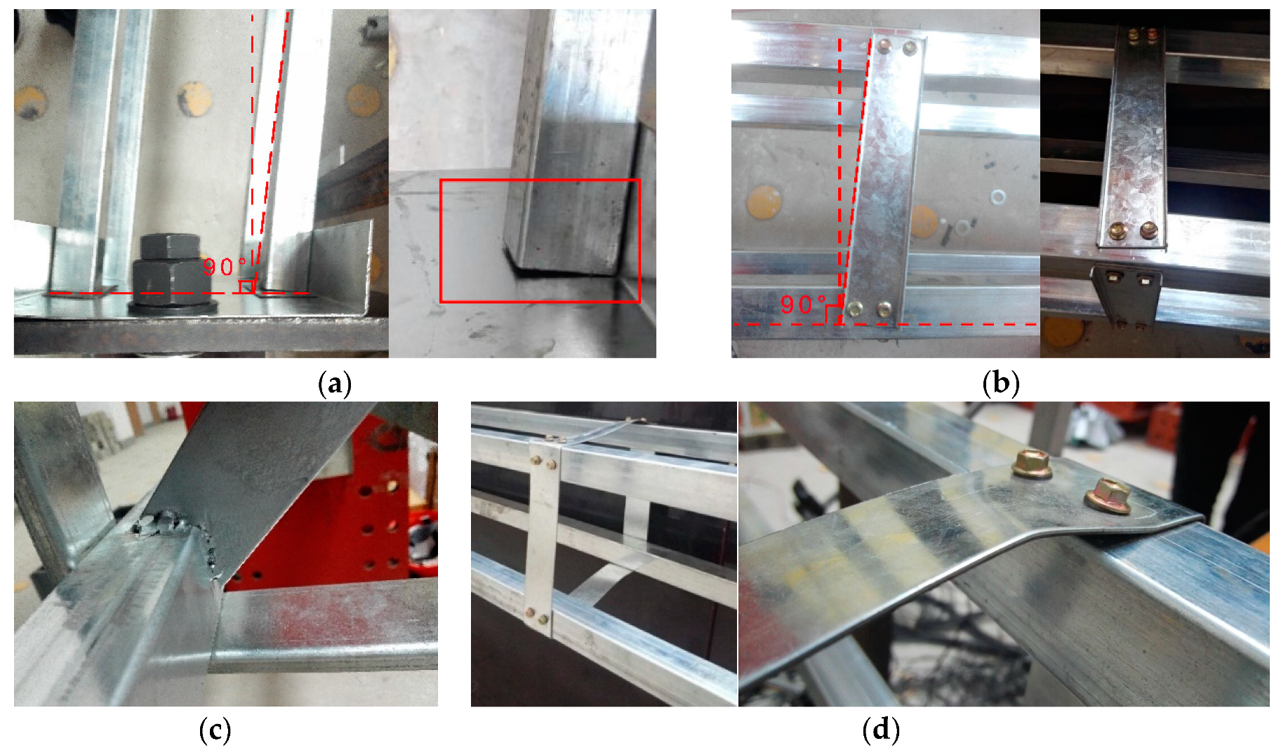
Figure 7.
Load-strain curves of connectors: (a) S1; (b) S2; (c) S3; (d) S4.
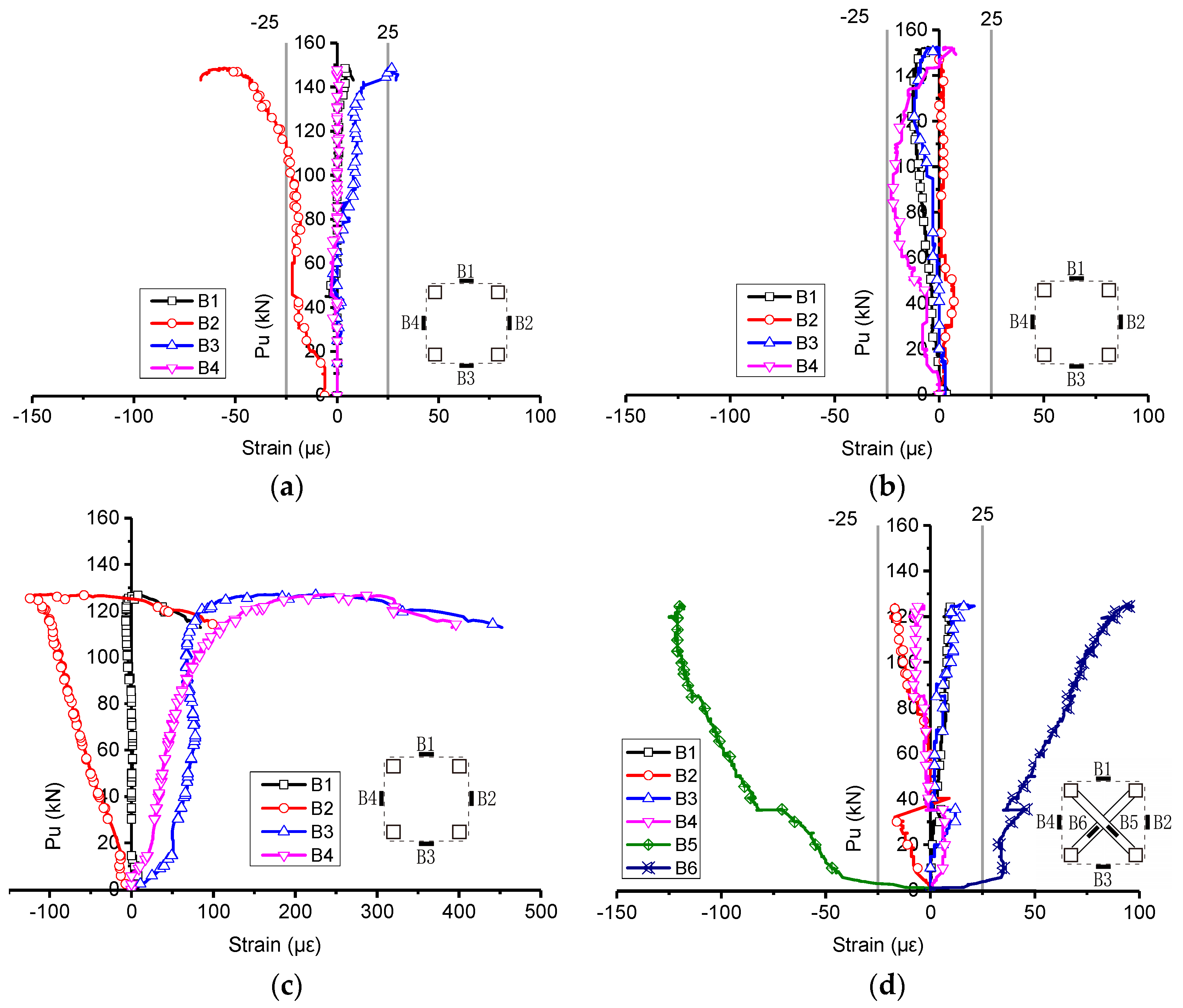
Figure 8.
Load-lateral displacement curves: (a) Lateral displacement at quarter-length point of S1; (b) Lateral displacement at half-length point of S1 and S4.
Figure 8.
Load-lateral displacement curves: (a) Lateral displacement at quarter-length point of S1; (b) Lateral displacement at half-length point of S1 and S4.
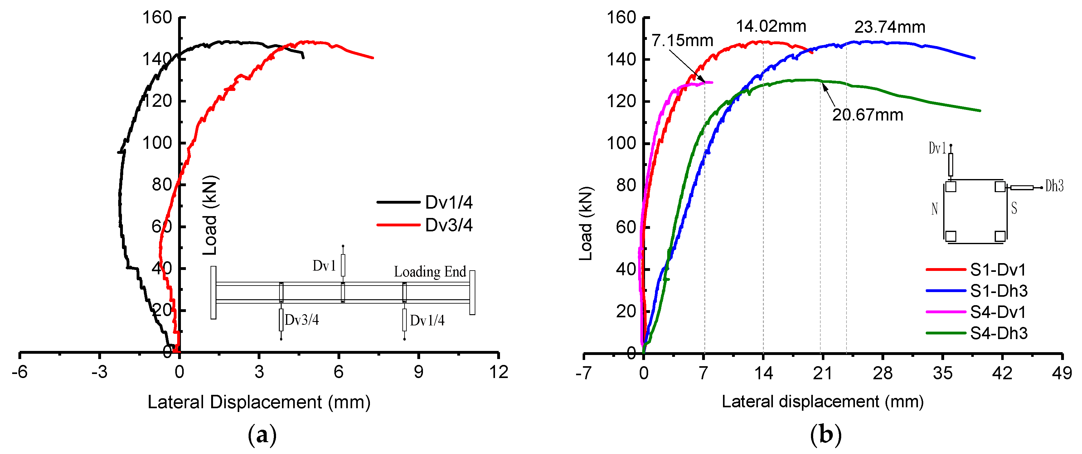
Figure 9.
Load-strain curves of tubes of S1: (a) T1; (b) T2; (c) T3; (d) T4.
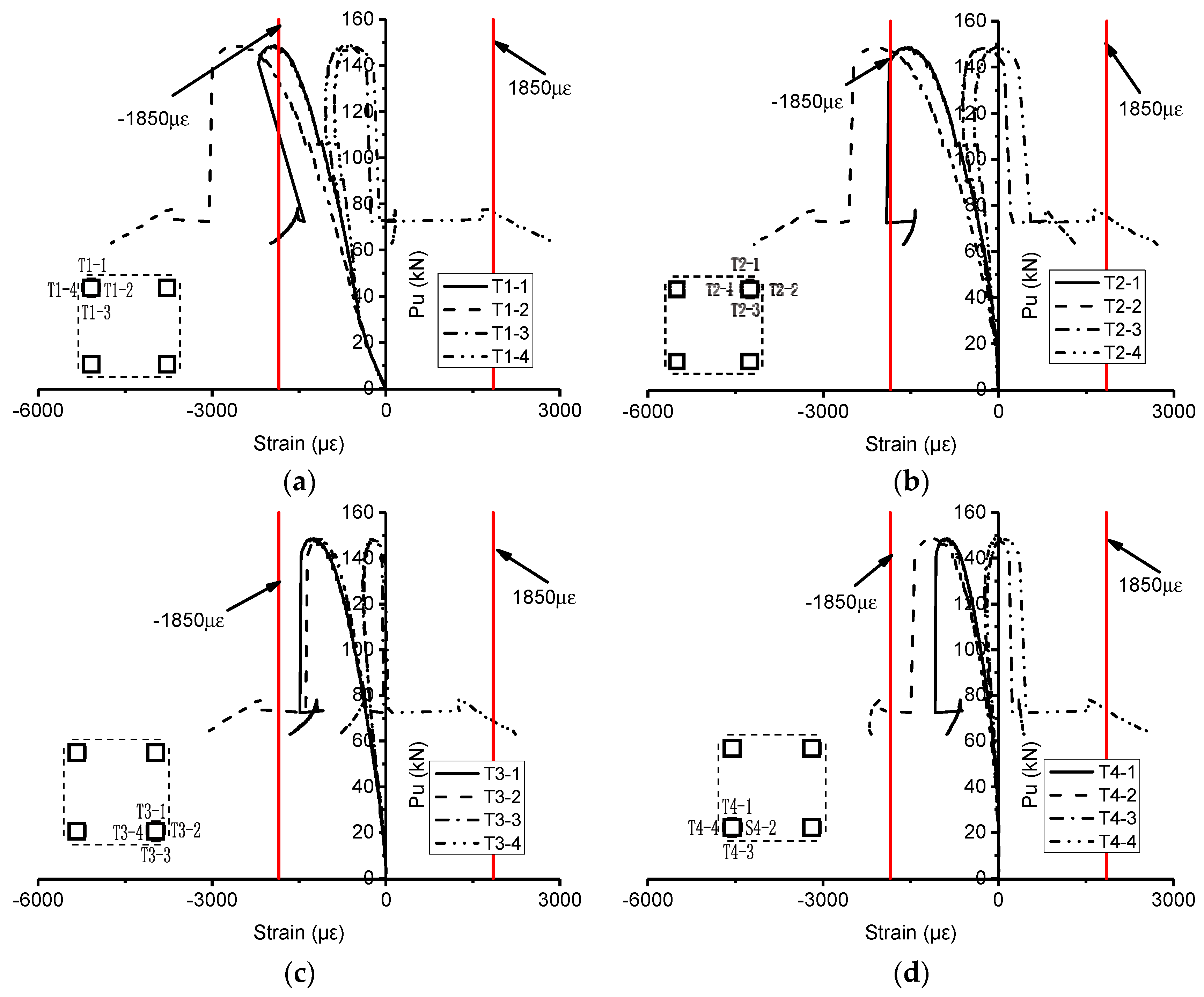
Figure 10.
Mises stress of specimens (unit: N/m2).
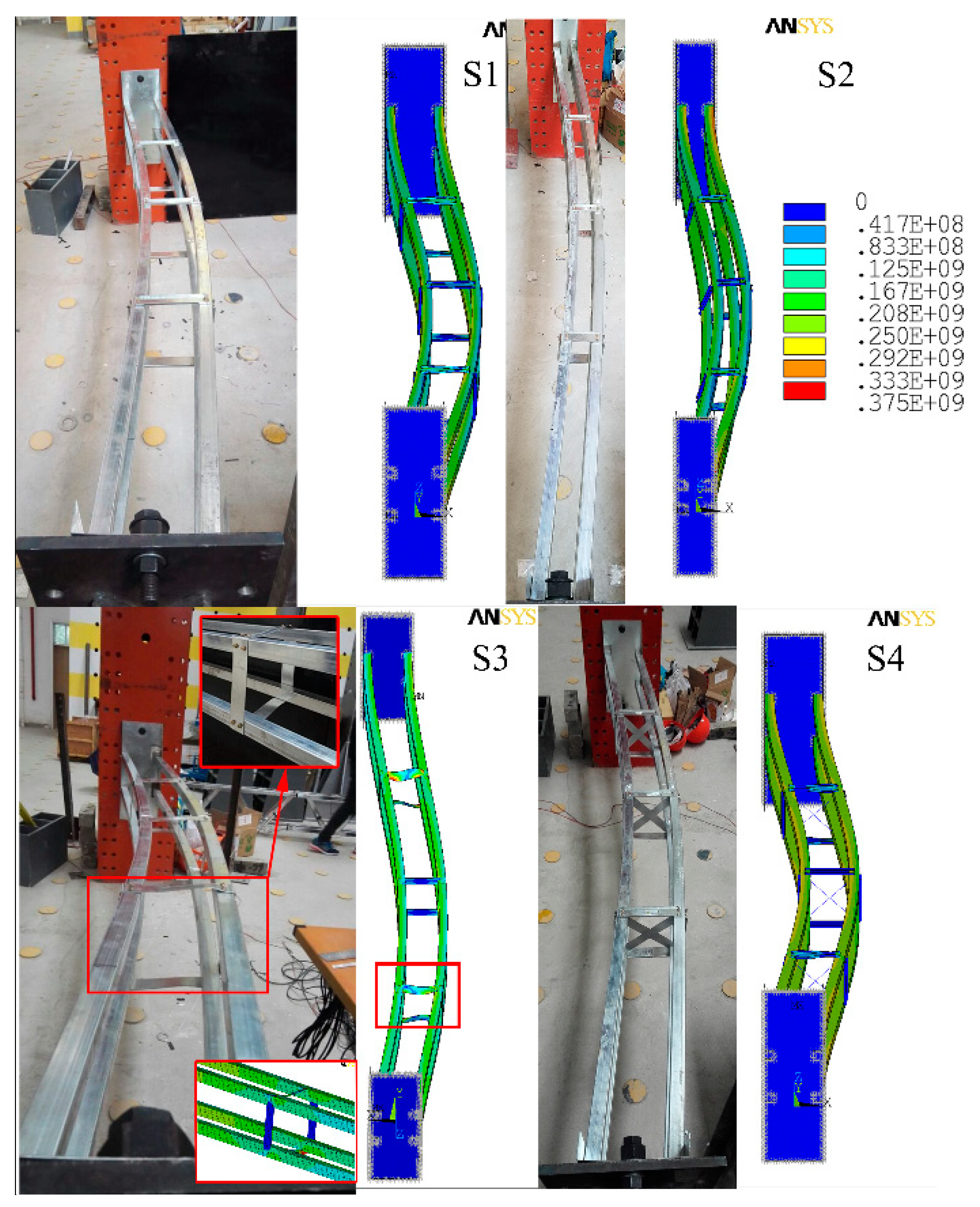
Figure 11.
Numerical simulation results and details (a) Load-axial shortening curves of S1; (b) Curve of spring force and displacement.
Figure 11.
Numerical simulation results and details (a) Load-axial shortening curves of S1; (b) Curve of spring force and displacement.
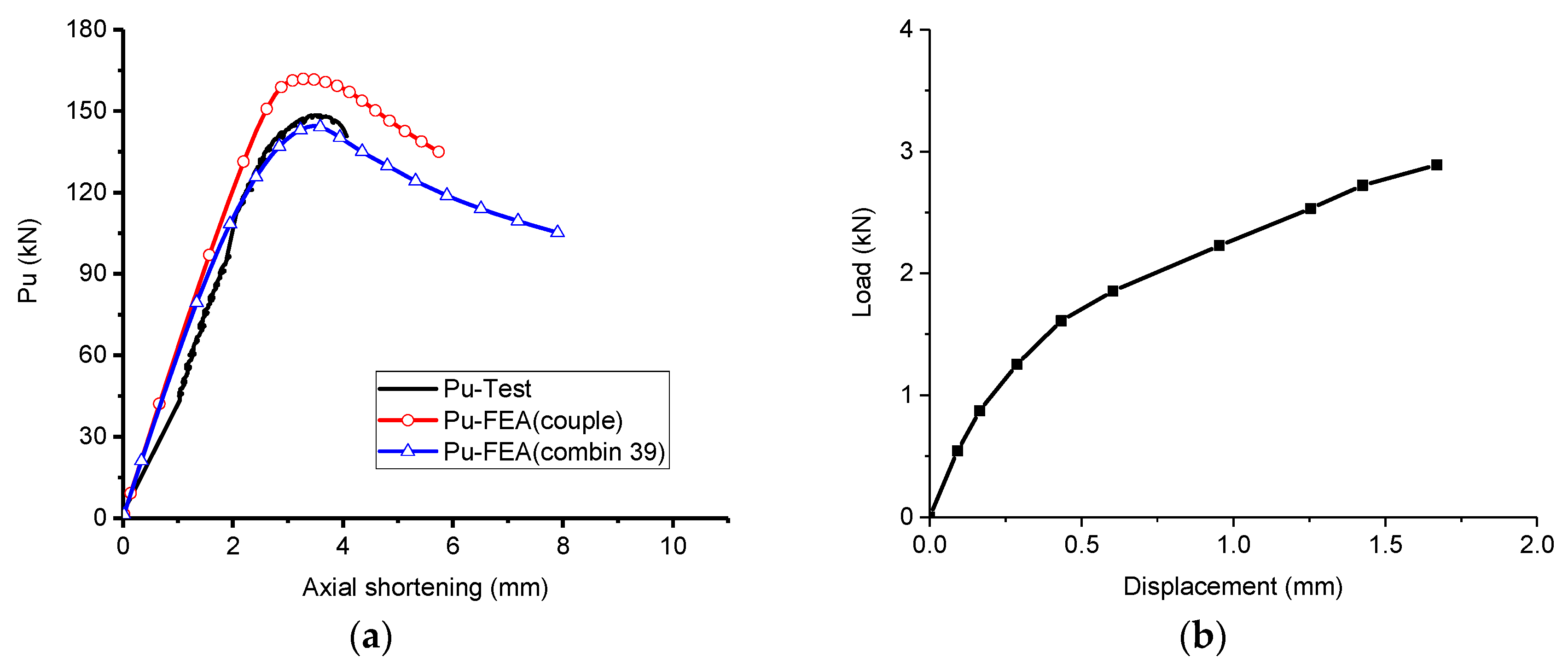
Figure 12.
Effect of web height of connector and adding connector at column ends.

Figure 13.
Plastic depressed deformation and Mises stress of tubes (unit: N/m2).
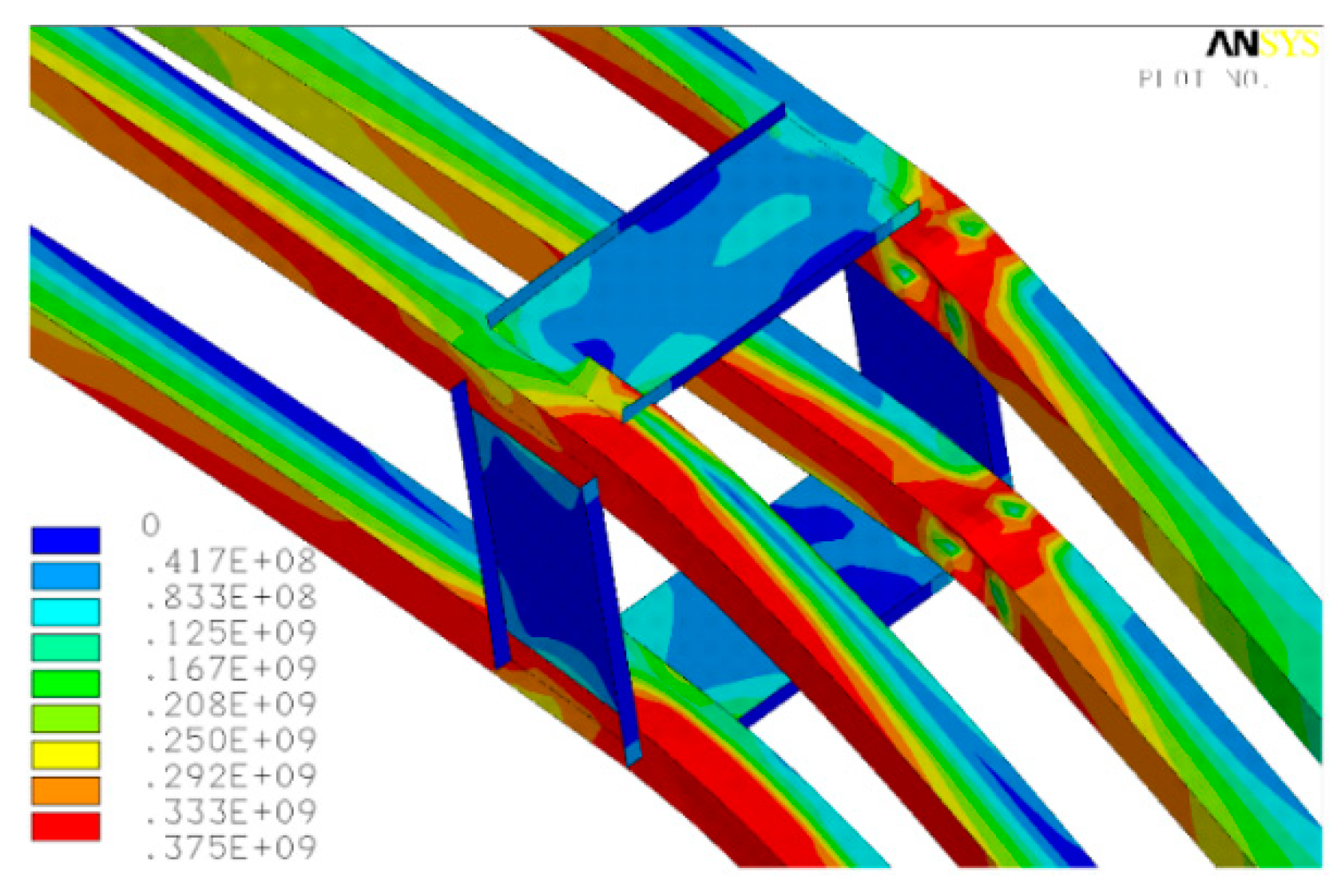
Figure 14.
Effect of number of connectors: (a) column length is 600 mm; (b) column length is 1200 mm; (c) column length is 1800 mm; (d) column length is 2400 mm; (e) column length is 3000 mm.
Figure 14.
Effect of number of connectors: (a) column length is 600 mm; (b) column length is 1200 mm; (c) column length is 1800 mm; (d) column length is 2400 mm; (e) column length is 3000 mm.


Table 1.
Details of specimens.
| No. | Specimen | Length (mm) | S 1 (mm) | W 2 (mm) | Section Form of Batten Plate | Transverse Diaphragm |
|---|---|---|---|---|---|---|
| S1 | L3000-S700-W200 | 3000 | 700 | 200 | channel | no |
| S2 | L3000-S700-W110 | 3000 | 700 | 110 | channel | no |
| S3 | L3000-S700-W200-Strip | 3000 | 700 | 200 | strip | no |
| S4 | L3000-S700-W200-X | 3000 | 700 | 200 | channel | yes |
1S: Spacing between connectors. 2W: Spacing between tubes.
Table 2.
Material properties.
| Specimen | Yield Stress σy (MPa) | Ultimate Stress σu (MPa) | σu/σy | Young’s Odulus E (GPa) | |
|---|---|---|---|---|---|
| tubes | 1 | 378 | 450 | 1.191 | 193 |
| 2 | 372 | 447 | 1.202 | 203 | |
| 3 | 375 | 451 | 1.204 | 216 | |
| Average values | 375 | 450 | 1.199 | 204 | |
| connectors and tracks | 1 | 352 | 360 | 1.022 | 180 |
| 2 | 343 | 349 | 1.017 | 165 | |
| 3 | 355 | 363 | 1.023 | 174 | |
| Average values | 350 | 357 | 1.021 | 173 | |
Table 3.
Results of test and finite element analysis.
| No. | Specimen | P-Test kN | P-FEA kN | P-FE/P-Test |
|---|---|---|---|---|
| S1 | L3000-S700-W200 | 148.55 | 161.01 | 1.08 |
| S2 | L3000-S700-W110 | 152.48 | 162.94 | 1.07 |
| S3 | L3000-S700-W200-Strip | 125.00 | 132.90 | 1.06 |
| S4 | L3000-S700-W200-X | 130.25 | 132.52 | 1.02 |
Table 4.
Strength-to-weight (STW) ratio of built-up columns and comparison between numerical results and design strength according to AISI-S100-12.
Table 4.
Strength-to-weight (STW) ratio of built-up columns and comparison between numerical results and design strength according to AISI-S100-12.
| No. | Specimen | L (mm) | N | S (mm) | P-FEA (kN) | STW Ratio | Pu-AISI (kN) | P-FEA/Pu-AISI |
|---|---|---|---|---|---|---|---|---|
| 1 | L3000S400-7 | 3000 | 7 | 400 | 202.0 | 773 | 303.3 | 0.67 |
| 2 | L3000S500-5 | 3000 | 5 | 500 | 190.3 | 765 | 295.5 | 0.64 |
| 3 | L3000S700-5 (end) | 3000 | 5 | 700 | 183.9 | 739 | 275.8 | 0.67 |
| 4 | L3000S600-4 | 3000 | 4 | 600 | 179.1 | 738 | 286.3 | 0.63 |
| 5 | L3000S700-3 L3000-S700-W200 L3000-S700-W110 L3000-S700-W200-Strip L3000-S700-W200-X | 3000 | 3 | 700 | 161.0 (148.6) (152.5) (132.9) (132.5) | 682 (629) (667) (543) (546) | 275.8 (275.8) (263.7) (275.8) (275.8) | 0.58 (0.54) (0.58) (0.48) (0.48) |
| 6 | L3000S1000-2 | 3000 | 2 | 1000 | 152.9 | 665 | 238.2 | 0.64 |
| 7 | L3000S1500-1 | 3000 | 1 | 1500 | 139.5 | 623 | 166.3 | 0.84 |
| 8 | L3000S3000-0 | 3000 | 0 | 3000 | 131.1 | 603 | 45.2 | 2.90 |
| 9 | L2400S400-5 | 2400 | 5 | 400 | 256.0 | 1248 | 303.7 | 0.84 |
| 10 | L2400S500-4 | 2400 | 4 | 500 | 242.4 | 1218 | 295.9 | 0.82 |
| 11 | L2400S600-3 | 2400 | 3 | 600 | 233.6 | 1212 | 286.7 | 0.81 |
| 12 | L2400S700-2 | 2400 | 2 | 700 | 206.4 | 1106 | 276.2 | 0.75 |
| 13 | L2400S1200-1 | 2400 | 1 | 1200 | 195.5 | 1084 | 210.2 | 0.93 |
| 14 | L2400S2400-0 | 2400 | 0 | 2400 | 196.4 | 1128 | 70.6 | 2.78 |
| 15 | L1800S400-4 | 1800 | 4 | 400 | 292.0 | 1879 | 304.0 | 0.96 |
| 16 | L1800S500-3 | 1800 | 3 | 500 | 302.1 | 2024 | 296.3 | 1.02 |
| 17 | L1800S600-2 | 1800 | 2 | 600 | 276.2 | 1932 | 287.0 | 0.96 |
| 18 | L1800S900-1 | 1800 | 1 | 900 | 262.9 | 1922 | 252.2 | 1.04 |
| 19 | L1800S1800-0 | 1800 | 0 | 1800 | 269.6 | 2065 | 125.5 | 2.15 |
| 20 | L1200S300-3 | 1200 | 3 | 300 | 335.7 | 3176 | 310.4 | 1.08 |
| 21 | L1200S400-2 | 1200 | 2 | 400 | 339.7 | 3415 | 304.3 | 1.12 |
| 22 | L1200S600-1 | 1200 | 1 | 600 | 326.2 | 3498 | 287.3 | 1.14 |
| 23 | L1200S1200-0 | 1200 | 0 | 1200 | 322.5 | 3705 | 210.6 | 1.53 |
| 24 | L600S300-1 | 600 | 1 | 300 | 336.6 | 6768 | 310.6 | 1.08 |
| 25 | L600S600-0 | 600 | 0 | 600 | 340.9 | 7832 | 287.4 | 1.19 |
| Mean | 1.11 | |||||||
| COV | 0.56 |
Note: LXSY-N: LX denotes the length of built-up column is X mm; SY denotes spacing between connectors is Y mm; N denotes the number of connectors is N. S denotes the spacing between connectors. The data in brackets denote the results of four specimens obtained from tests.
© 2019 by the authors. Licensee MDPI, Basel, Switzerland. This article is an open access article distributed under the terms and conditions of the Creative Commons Attribution (CC BY) license (http://creativecommons.org/licenses/by/4.0/).
Share and Cite
MDPI and ACS Style
Chen, X.; Xia, J.; Xu, B.; Ma, R. Mechanical Performance of Built-Up Columns Composed of Four Cold-Formed Square Steel Tubes. Appl. Sci. 2019, 9, 1204. https://doi.org/10.3390/app9061204
AMA Style
Chen X, Xia J, Xu B, Ma R. Mechanical Performance of Built-Up Columns Composed of Four Cold-Formed Square Steel Tubes. Applied Sciences. 2019; 9(6):1204. https://doi.org/10.3390/app9061204
Chicago/Turabian StyleChen, Xiaomiao, Junwu Xia, Bo Xu, and Renwei Ma. 2019. "Mechanical Performance of Built-Up Columns Composed of Four Cold-Formed Square Steel Tubes" Applied Sciences 9, no. 6: 1204. https://doi.org/10.3390/app9061204
Note that from the first issue of 2016, this journal uses article numbers instead of page numbers. See further details here.