Leg Trajectory Planning for Quadruped Robots with High-Speed Trot Gait


State Key Laboratory of Robotics and System, Harbin Institute of Technology, Harbin 150001, China
*
Author to whom correspondence should be addressed.
Appl. Sci. 2019, 9(7), 1508; https://doi.org/10.3390/app9071508
Submission received: 14 March 2019
/
Revised: 7 April 2019
/
Accepted: 9 April 2019
/
Published: 11 April 2019
(This article belongs to the Special Issue Advances in Mechanical Systems Dynamics)
Abstract
:In this paper, a single leg platform for quadruped robots is designed based on the motivation of high-speed locomotion. The leg is designed for lightweight and low inertia with a structure of three joints by imitating quadruped animals. Because high acceleration and extensive loadings will be involved on the legs during the high-speed locomotion, the trade-off between the leg mass and strength is specifically designed and evaluated with the finite element analysis. Moreover, quadruped animals usually increase stride frequency and decrease contact time as the locomotion speed increases, while maintaining the swing duration during trot gait. Inspired by this phenomenon, the foot-end trajectory for quadruped robots with a high-speed trot gait is proposed. The gait trajectory is planned for swing and stance phase; thus the robot can keep its stability with adjustable trajectories while following a specific gait pattern. Especially for the swing phase, the proposed trajectory can minimize the maximum acceleration of legs and ensure the continuity of position, speed, and acceleration. Then, based on the kinematics analysis, the proposed trajectory is compared with the trajectory of Bézier curve for the power consumption. Finally, a simulation with Webots software is carried out for verifying the motion stability with two trajectory planning schemes respectively. Moreover, a motion capture device is used for evaluating the tracking accuracy of two schemes for obtaining an optimal gait trajectory suitable for high-speed trot gait.
1. Introduction
Legged robots are more suitable for applications with rough terrain and complex cluttered environments compared to wheeled robots [1,2,3]. With respect to the leg length, quadruped robots can freely select contact points while making contact with the environment. Therefore, it is promising that they can be used for rescuing people in forests and mountains, climbing stairs, to carry payloads in construction sites, and so on [4]. Recently, several quadruped robots are being developed which are equipped with hydraulic actuators or electric actuators. For example, Boston Dynamics developed a series of robots equipped with hydraulic actuators with high energy density. Hydraulic drive quadruped robots, such as Big Dog [5] and HyQ [6], make use of the characteristics of the high power density of hydraulic pressure to realize a stronger carrying capacity and motion ability. However, their large noise and size have limited their applications to outdoor applications. Moreover, they require additional hydraulic source and oil circuit, which often makes the structure more complex. Different from that, quadruped robots equipped with electric actuators can even be used to indoor environments, such as SpotMini [7], ANYmal [8], and MIT Cheetah [9,10,11]. Amongst them, MIT Cheetah realized a fast, efficient design with advanced proprioceptive actuator design [9]. ANYmal applies a bioinspired actuator design, making it robust against impact, while allowing accurate torque measurement at the joints. However, the complicated actuator design also increases cost and compromises the power output of the robot [4]. SpotMini did not publish their detailed researches; however, public media has released its capabilities, such as climbing stairs and stabilizing several gaits [7].
On the other hand, high-speed locomotion involves high acceleration and extensive loadings on the legs, which brings a trade-off between weight and strength of legs [12]. There are generally two main ways to apply the leg motors for quadruped robots: putting the motor at each joint and concentrating the motor at the shoulder. Quadruped robots, such as ANYmal, adopt the method of putting motors at each joint to achieve a fully actuated motion with high compliant series elastic actuation, suitable for highly dynamic motions. Although by using this method the quadruped robots are easier to control and can walk steadily, the swing speed of their legs is slow, which leads to low walking speed. Some quadruped robots, such as SpotMini and MIT Cheetah, adopt the method of putting motors at the shoulder. This strategy can make the leg mass and inertia of the swinging parts of the legs very low and achieve a high running locomotion. Moreover, as for the leg structure of quadruped robots, the main leg structure is a two-joint structure, which is used in most quadruped robots, such as ANYmal, Wildcat [13], SpotMini, etc. This structure is simple, intuitive, and easy to control. However, from a biological point of view, toed animals, such as tigers, leopards, lions, and wolves, have a three-joint structure in their legs, which imparts great advantages in running speed and energy efficiency. MIT Cheetah adopted the three-part structure, which achieved a 6 m/s running speed, and the ability to cross obstacles with high energy efficiency [14]. Also, Cheetah-cub designed with pantograph leg configuration to simplify the control of three links with only two joints and reached a running trot with short flight phases [15]. Besides, a real “cat-sized” robot called Pneupard also explored this same pantograph method [16]. The method of putting motors at the shoulder has been proved to be effective on the high running locomotion. However, there is still a lack of analysis with infinitesimal kinematics for a favorable leg structure of quadruped robots with high-speed locomotion.
Except for the suitable leg design, the stable gait trajectory is the basis of movement stability for quadruped robots. Quadruped animals can achieve various gait patterns such as walk, trot, pronk, bound, half-bound, rotary gallop, transverse gallop, etc. [17]. Among them, the trot gait is the most widely used gait, which is very simple and effective. The duration of leg swing is always constant for both trot and gallop gait, although quadruped animals adjust their stride frequency while trotting, and adjust stride length for gallop gait [17]. Also, the leg trajectory planning is important for robots’ stability with adjustable trajectories. Saputra et al. designed a Bézier curve based passive neural control method applied in bioinspired locomotion for decreasing the computational cost [18]. Lee et al. designed a trajectory with a Nonuniform Basis Spline (NUBS) curve to effectively overcome obstacles [19]. Hyun et al. used properties of the Bézier curve for desirable swing-leg dynamics [11]. However, suitable gait trajectories considering energy efficiency are seldom researched.
Therefore, in this paper, the motivation is to design an electrically actuated leg platform for quadruped robots with high-speed locomotion. The method of putting motors at the shoulder is adopted for reducing the leg inertia during the swing. In particular, the suitable leg structure and high-efficiency gait trajectory are analyzed and verified on the leg platform. The novel designed leg trajectory combines cosine curve, quintic curve, and hexagonal curve to minimize the maximum acceleration of legs and ensure the continuity of position, speed, and acceleration during high-speed trot gait. The efficiency is evaluated by measuring the endpoint acceleration, stability, and power consumption compared with the Bézier curve [9]. Furthermore, an optotrak sensor is used for measuring the actual foot-end trajectory of the two schemes. The sensor can track and analyze kinetics and dynamic motion in real-time, which is a more direct and precise method to measure the actual endpoint position, especially when the motor encoder has low precision.
The remainder of this paper is organized as follows. Section 2 introduces the detailed design of the leg and the finite element analysis of the leg for the trade-off between the leg weight and strength. Moreover, the inverse kinematic analysis of the single leg gait and two different gait trajectory planning schemes are given. Section 3 gives the simulation result of two schemes in trajectory planning with Webots and experimental results measured with the optotrak sensor. Section 4 will discuss the simulation and experimental results. At last, the conclusion and direction of future works are given.
2. Materials and Methods
2.1. Leg Design of the Quadruped Robot
2.1.1. Leg Structure Comparison with Kinematics Analysis
The two-joint and three-joint articulated leg structures were considered during the initial leg structure design. By comparing the differences on the aspect of geometry and kinematics, the manipulability, obstacle avoiding ability, and occupied space for legs were analyzed.
Figure 1 shows the schematic for the three-joint leg structure on the left and two-joint leg structure on the right. It is assumed that the total link lengths for both two leg structures are identical and decided by the height of robots. The manipulability which measures at state with respect to manipulation vector is defined as Equation (1) [20]:
For the three-joint leg structure, the Jacobian matrix can be calculated as Equation (2):
Therefore, the manipulability can be calculated with .
Similar, the Jacobian matrix for the two-part leg structure can be calculated as Equation (3):
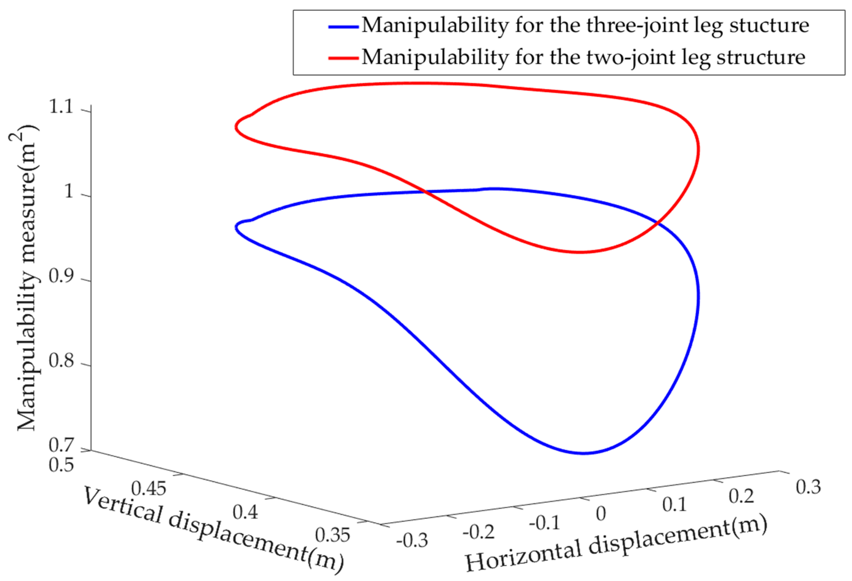
The manipulability can be calculated with . Here the lengths of , , and are given in the Table 1. For the two-joint leg structure, the manipulability can get a maximum value when the equates to . For comparing the manipulability of two leg structures during one gait cycle, the Bézier curve for the swing phase and the cosine function for the stance phase were used. The manipulability during one gait cycle is shown in Figure 2.
The leg structure should also protract the leg with enough ground clearance to avoid obstacles. Therefore, we compared the angles and , as shown in Figure 1, which can be calculated with Equations (4) and (5):
where h represents the height between the shoulder part of leg to the ground. The obstacle avoiding ability for the three-joint and two-joint leg structures is shown in Figure 3.
At last, the space occupied for two leg structures was also compared. Assuming that and , we can get
Setting and considering the height of the quadruped, the result can be obtained as shown in Figure 4.
The leg configuration between the three-joint and two-joint structures can be more clearly found in Figure 5. From these kinematics analyses, it can be found that, when h is selected as 0.343 in our leg design, the three-part leg structure has enough ground clearance to avoid obstacles. The occupied space after retracting the leg for the three-joint leg structure is much smaller than that of the two-joint leg structure when h is set as 0.343 m; the manipulability is similar between the two leg structures. By combining the biological point of view and these kinematics analyses, the three-joint leg structure was determined.
2.1.2. Detailed Leg Design with Three-joint Leg Structure
The leg was designed for high-speed locomotion of quadrupeds and inspired by the design of MIT Cheetah [9]. The physical leg parameters are shown in Table 1. The total mass of the leg is ~5.5 kg, where the swing part (1.284 kg) only occupies 23% of total mass. Moreover, the center of leg mass is only 84 mm away from the rotation center of the shoulder module, which helps reduce leg inertia during the swing. Shoulder and knee actuators with planetary gears are coaxially located at the shoulder module part for achieving a coupled motion of two joints, as shown in Figure 6, thus that the mass and leg inertia can be decreased. In detail, the knee actuator drives the knee joint through a parallel linkage, while the shoulder actuator directly drives the shoulder joint. The leg consists of the thigh, calf, and foot, where a parallel linkage connects the calf and foot. Therefore, two parallel linkages can drive the motion of the foot and thigh in parallel without an extra actuator on foot.
The detailed design of the shoulder module is shown in Figure 7. There are two identical motors, including a knee motor and a shoulder motor in the shoulder module. The shoulder motor drives the knee motor part and thigh part to rotate through the hollow motor shaft and a planetary gear reducer. The shoulder module is designed as a thin-walled structure and is very compact in order to reduce its mass. The hollow motor shafts and gears are made of T4 titanium alloy to ensure their strength. On the contrary, the elements bearing less stress are made of 7075 aluminum alloy to ensure their light weight.
Actuators for quadruped robots with high-speed locomotion should provide high torque density which manages the dynamic physical interactions well. The proprioceptive actuator paradigm achieves a combination of high-bandwidth force control, high torque density, as well as impact mitigation [9]. For example, NABi-V2 utilizes six-back drivable high-power density electromagnetic actuators with a low gear ratio single-phase planetary gearbox to realize proprioceptive, force-controlled dynamic locomotion [12]. Similarly, a single-stage planetary gear reduction (main material is titanium alloy, and weight is 0.113 kg) with low gear ratio (6:1) combined with high torque density frameless motors was applied during our leg design.
Moreover, during the high-speed locomotion, when the leg touched the ground, both linkages were pulled by two opposite forces, and neither bending moment nor torque is applied on the linkages. Therefore, these two linkages can be very thin. Hollow shafts are used in the joints of the leg, and ribbed plates are applied on the legs, which also decrease the total mass. In particular, the joints of linkages are so small that standard bearings cannot be used, so wear washers and dry bushing were adopted, which can effectively reduce the friction of linkages’ joint by the self-lubrication characteristics of the dry bushing.
2.2. Finite Element Analysis (FEA) of the Leg
As mentioned above, there is a trade-off between the total leg weight and its strength. Therefore, in order to reduce the total weight and inertia of the leg without losing too much strength, the leg structure is mainly connected by ribbed plates with only 4-mm-thin plates in the middle, and the inclination angle of ribbed plates is 45 degrees to facilitate better performance of bearing pressure and bending moment. What is more, many thin-walled structures and lightweight materials were used in both motor and leg structure, which is likely to lead to insufficient strength and stiffness. Therefore, it is necessary to confirm the strength of the leg by Finite Element Analysis (FEA).
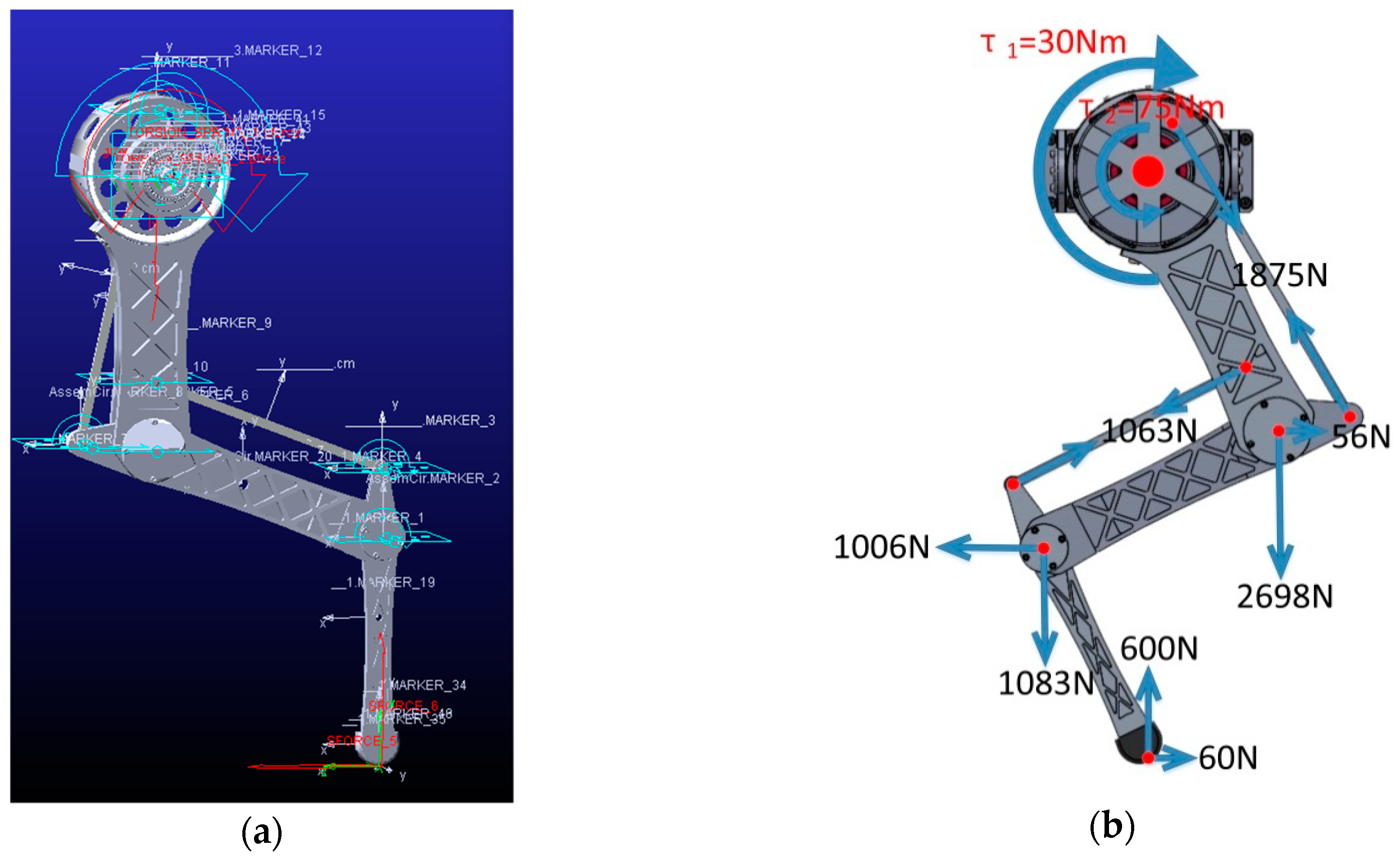
During the locomotion of a quadruped robot, the leg movement mainly consists of two parts: a stance phase and a swing phase. The stance phase is a moment when the legs are stressed, and the weight of the robot body is supported by only two legs in the middle of the stance phase during trot and bound gaits. Considering that the quadruped robot needs to complete tasks like jumping over obstacles, which may generate an impact 2 to 3 times the weight of body [13], it is estimated that the total weight of the designed quadruped robot is ~40 kg, so the maximum impact distributed to each leg is !600 N. At the same time, the legs need to give the body a forward motion force, which was set to 1/10 of the impact (60 N). These two forces are applied to the endpoint of the leg model imported into Adams as load forces, and the forces generated in each part of the leg can be measured as shown in Figure 8.
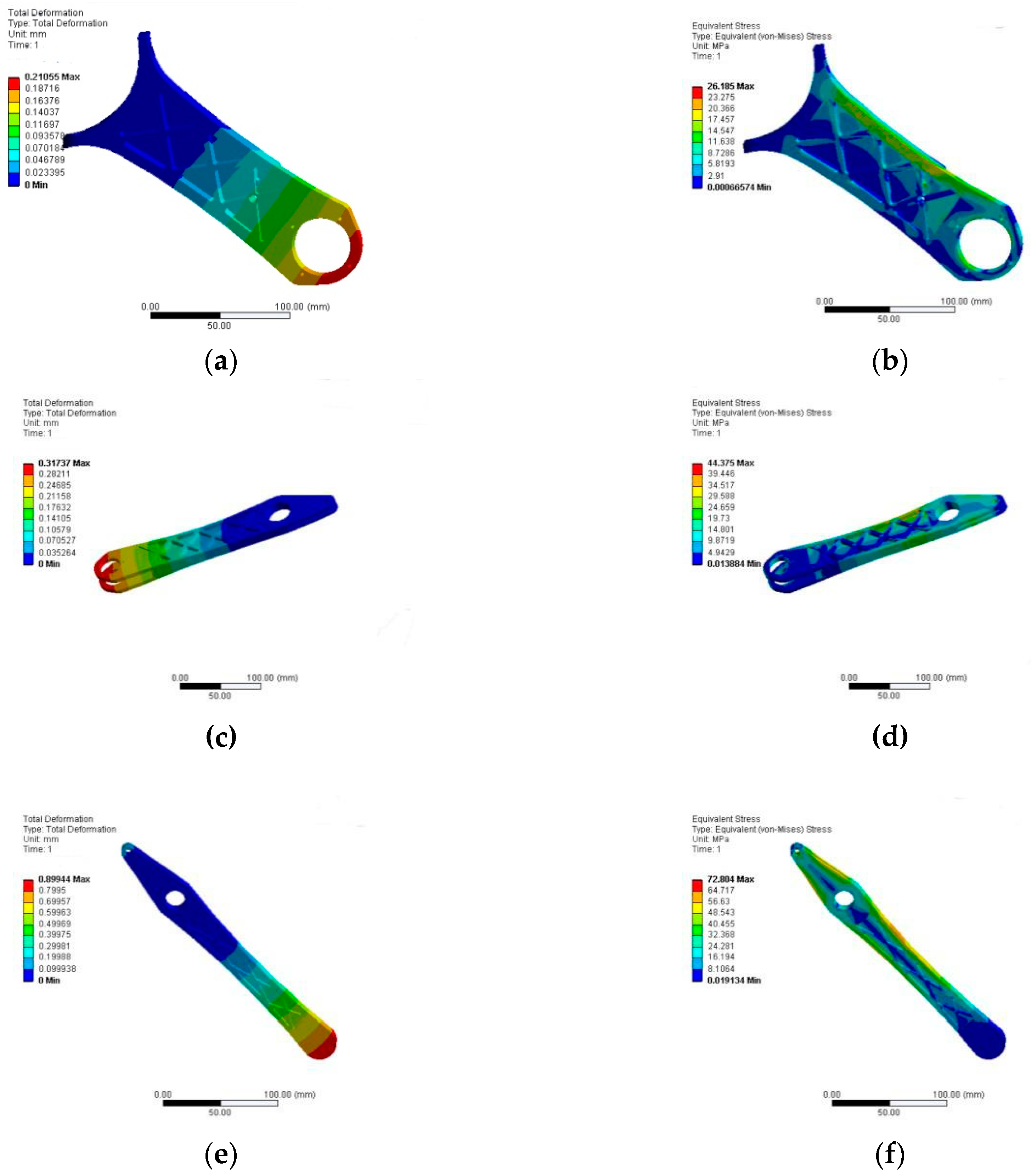
From the force analysis result, we know that each joint of the leg bears a large force under the ultimate load at the endpoint of the leg. In order to increase accuracy during the strength and stiffness checking, the forces obtained by the force analysis in Adams was further used as the load input for the deformation and stress analyses of each part by FEA with ANSYS software. The results are shown in Figure 9.
It can be found that the maximum stress on each part of the leg is 245.6 Mpa, that is, less than 455 Mpa, which is the material strength of the 7075 aluminum alloy, and the structural strength of the leg meets the requirements with a high safety factor of 1.85. Also, there is a certain amount of deformation as a result of using a thin-walled structure and light aluminum alloy material resulting in lower stiffness brought about by the relatively lower weight of the leg. Moreover, from the view of natural animal running, the contact between their legs and the ground is a flexible contact rather than a rigid contact, which can decrease the peak force between feet and the ground and make the legs bear larger force. Therefore, the structure of the leg having a certain amount of deformation during the movement can be beneficial for buffering.
2.3. Inverse Kinematic Analysis
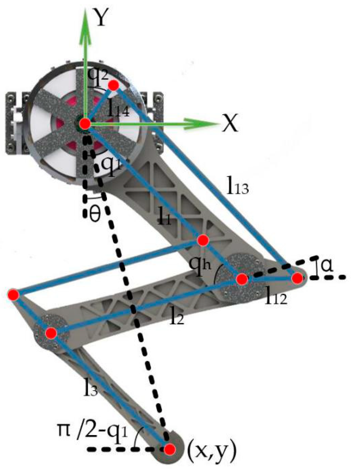
In order to accomplish the foot-point trajectory control of the leg, it is necessary to derive the inverse kinematics formula for the leg. The leg model is shown in Figure 10, where q1 represents the rotation angle of the shoulder part. Because the knee motor rotates by the shoulder motor, the actual rotation angle of the knee part will be (q1 + q2).
The final expression formulas are shown as Equations (8)–(10):
where, qh is the angle between the calf and the thigh; θ is the angle of leg’s endpoint with the opposite direction of Y; l1, l2, l3, l12, l13, and l14 are the length of the linkages in the four-bar structure; α is the angle between the calf and the linkage l12; and (x,y) is the coordinate of the endpoint of the leg.
2.4. Leg Trajectory Planning
2.4.1. Stance Phase Trajectory Design
The leg movement of a quadruped robot can be divided into two phases: the stance phase and the swing phase. Consider that high acceleration and extensive loadings will be exerted on the legs during the stance phase. If only the position control is used, it will easily bring a greater rigid impact to the quadruped robot’s body, which does not benefit stable walking or running and will also cause damage to the structure. Therefore, the stance and swing phases are separately designed with position control and impedance control. When the leg contacts the ground, an impedance control method will be applied to ensure the flexible contact between the leg and ground, which can reduce the impact effectively [21,22].
In order to reduce the impact between the leg and ground when the leg leaves or touch the ground, the X-direction motion of the stance phase is designed as a uniform velocity. The formulas of the X-direction of the stance phase are shown as Equations (11) and (12):
where L is the leg stride in a gait cycle, Tst is the time of the stance phase, and Vdesire is the desired speed of the robot.
Consider that the cosine function has a good performance in smoothness, so the cosine function, which was also used in other robots [19,23], was used in the trajectory of the stance phase. Considering that the leg will bear an impact and generate deformation when it touches the ground and the impedance control is used to resist impact in the stance phase, it needs a virtual displacement △ to ensure the body stability of quadruped robot. The Y-direction formula of support phase is shown as Equation (13):
2.4.2. Swing Phase Trajectory Design
The objective of the swing phase trajectory design is to protract the leg with enough ground clearance for avoiding obstacles and to have desirable swing leg retraction rate for reducing energy losses of running during touch down motion [24]. Consider that the leg is not affected by environmental forces so it can achieve higher speed and acceleration. Therefore, the period of the swing phase Tsw is defined as 0.25 s, calculated according to the maximum rotation speed of motors. Two schemes of the trajectory in the swing phase are proposed based on the spline curve and Bézier curve respectively.
Scheme I: Trajectory design with spline curve
The basic principle of this scheme is to minimize the maximum acceleration of legs as much as possible during the swing phase and ensure the continuity of position, speed, and acceleration. The planning trajectory is shown in Figure 11 with four increased velocities.
In order to avoid the high order polynomial trajectory planning, the trajectory in the swing phase is divided into 0 to 0.5TSW and 0.5TSW to TSW in the X direction. During 0 to 0.5TSW, for guaranteeing the touch-down and leave-off points between the swing phase and stance phase have better smoothness, it is necessary to ensure the position, speed, and acceleration continuously, which are given by Equations (14), (15), and (16):
Similarly, for ensuring the acceleration changes slightly and smoothly in the X direction and limiting the trajectory length of the swing phase to be appropriate, the time reaching zero velocity, TSW,VSW,x=0, which is a variable parameter with Vdesire, should be limited by Equation (17):
In the X direction, the trajectory is in the acceleration stage before 0.5TSW, and then in the deceleration stage. At the time of 0.5TSW, in order to ensure that the acceleration is small and continuous between the two stages, the acceleration and position should be zero, which are given by Equations (18) and (19):
From Equations (14) to (19) above, the five-order spline curves in the direction of X can be fitted from 0 to 0.5TSW, and the curves between 0.5TSW and TSW are obtained symmetrically.
The trajectory in the Y direction is also divided into two parts: 0 to 0.5TSW and 0.5TSW to TSW. It is also necessary to ensure that the position, velocity, and acceleration are continuous at the moment connecting the stance phase and swing phase in the part of 0 to 0.5TSW, which are given by Equations (20)–(22):
The highest position of the swing phase is limited at P1, in which the velocity and acceleration are zero, which are given by Equations (23)–(25):
Therefore, the five-order spline curve in the Y direction during the period from 0 to 0.5TSW can be fitted by Equations (20) to (25). For a smooth change between 0 to 0.5TSW and 0.5TSW to TSW, one extra condition is added for ensuring the jerk continuously. Thus, a six-order spline curve can be fitted.
Scheme II: Bézier curve
In this scheme, the trajectory of the swing phase can be obtained by Bézier curve, which is a smooth curve controlled by several points. MIT Cheetahs also used this curve to obtain a smooth swing phase trajectory [9], and a similar method was used in a quadruped robot, called AiDIN-IV [19]. The formula is written as Equation (26):
where Pi is the fitting point. The Bézier curve has several properties: (1) double coincidence fitting points determine a zero-velocity point; (2) triple coincidence fitting points determine a zero acceleration point; (3) and , . According to these properties, a smooth curve can be obtained by twelve control points as shown in Table 2. The shape of the trajectory is shown in Figure 12.
3. Results
3.1. The Features of Two Schemes
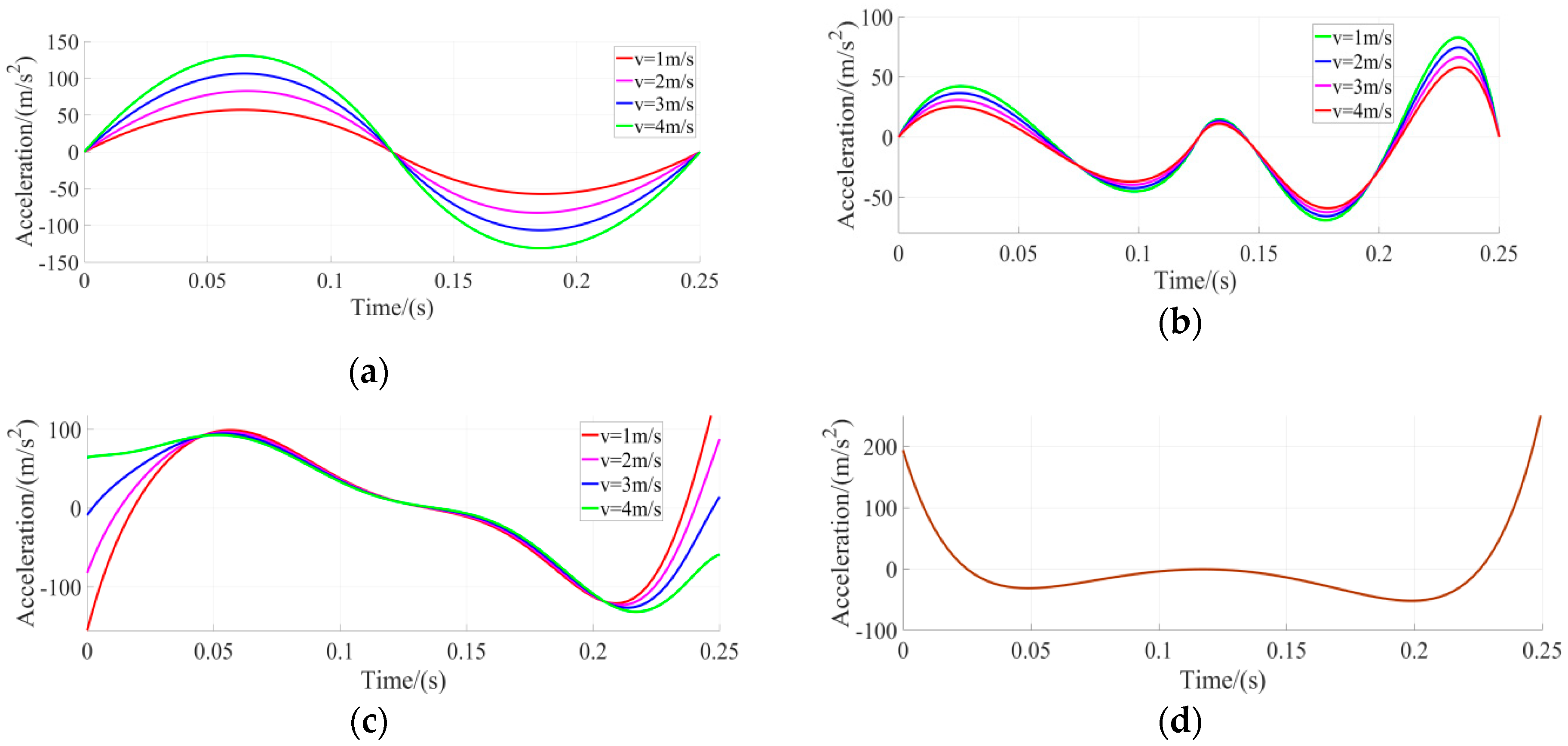
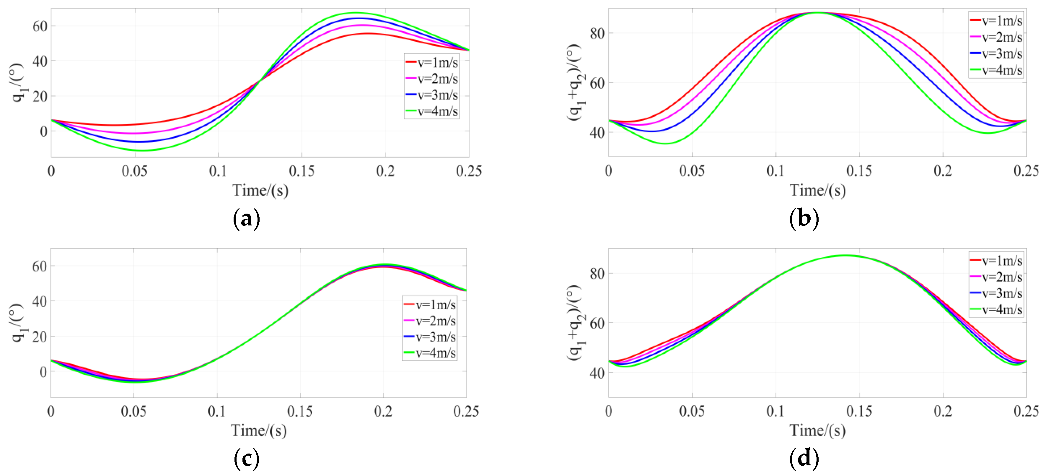
Comparing the swing phase trajectory acceleration of spline curve with that of the Bézier curve as shown in Figure 13, a curve with continuous acceleration cannot be obtained. Moreover, the acceleration of the Bézier curve at a contact point with the stance phase cannot reach 0, which means that there will be an impact force on the ground, and the maximum value of its acceleration curve is also larger than that in the spline curve. As to the spline curve trajectory, it will be more difficult to obtain the trajectory. Although there are many fitting conditions, it can obtain continuous curves with the stance phase, velocity, and acceleration, because the impact on the ground will be relatively small. However, from the analysis of Figure 14, in both schemes, the rotation angle for the shoulder and knee motors are changed continuously.
3.2. Simulation
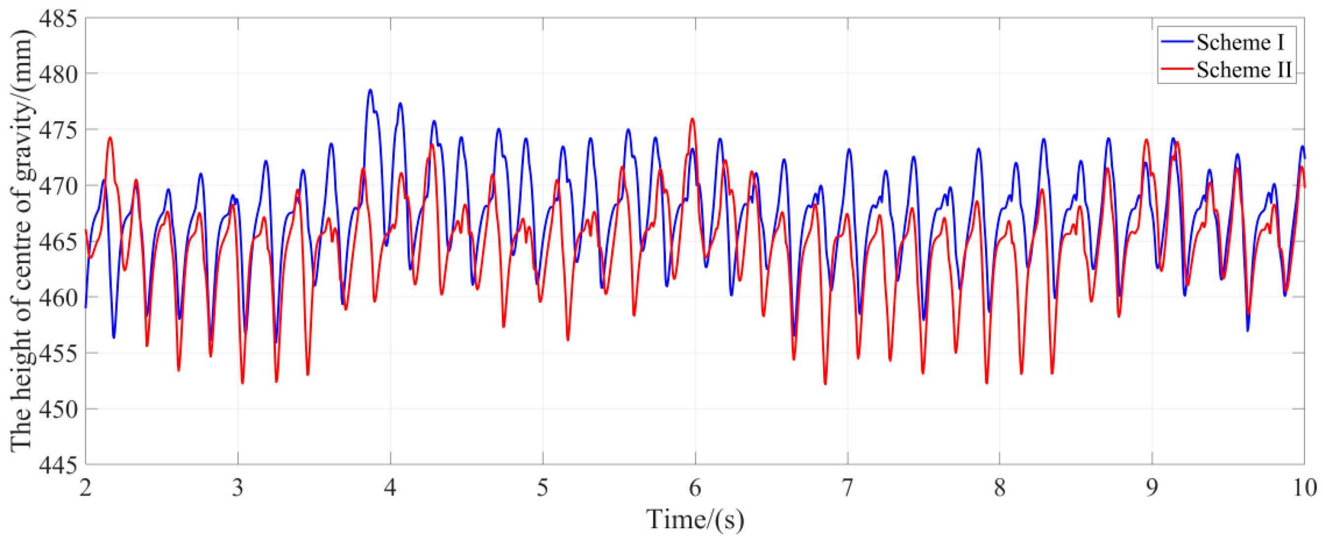
From the above results, it can be seen that the two leg trajectories have different properties, but their movement stability performance on a quadruped robot is still unknown. Therefore, in this section, the Webots software (Cyberbotics Ltd.) is introduced to simulate the motion stability of a quadruped robot under two high-speed gait trajectories. A model, which has the same physical parameters of the designed leg, was built, and two different gait trajectories were applied. The simulation results are shown in Figure 15. The desired speed was set as 2 m/s, which is a relatively high speed for quadruped robots. During the stance phase, an impedance controller was added for both of two schemes with appropriately set parameters of K = 80 Nm/rad and C = 5 Nms/rad. A distance sensor was placed in the center of the robot to measure the height change of the center of gravity of the quadruped robot from the ground for testing the new proposed gait trajectory and comparing the stability between two gait trajectories as shown in Figure 16.
3.3. Experiment
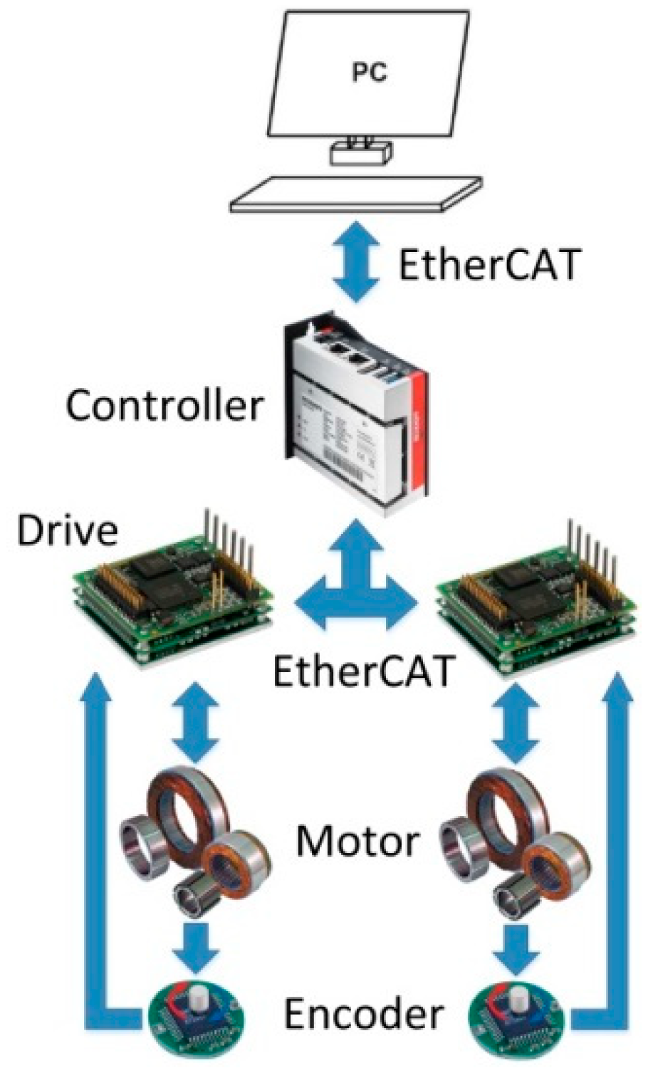
The hardware configuration of the single leg platform main consists of a PC, a controller (C6015, Beckhoff), two motor drives (G-SOLTWI10/200EE1, Elmo), two frameless motors (127P1, 380W, Allied Motion), and rotary magnetic encoders (RMB20SC13BC10, Renishaw), as shown in Figure 17. The controller has a dual-core CPU of 1.92 GHz with a rapid data computing capability. Moreover, the size of the controller is only 96 mm x 91 mm x 41 mm, which can greatly save space. The custom driven unit with a frameless motor with high torque density was specific designed, which significantly reduces the weight of the leg structure. Additionally, this motor can provide a sufficient torque of 21 Nm for high-speed running and jumping. Considering that the legs will bear periodic impact load during movement, magnetic encoders were used in the leg that can separate the encoder from the rotating shaft and avoid damage caused by the impact between the encoder and the shaft.
During the high-speed locomotion of the quadruped robot, its legs need to swing periodically and quickly, so the legs need to complete a swing trajectory in a very short time, which requires that the control cycle time be short enough to follow the trajectory [24]. Therefore, both the controller and drives need to have high real-time computing ability and high signal transmission speed. Therefore, an EtherCAT bus was chosen from PC to driver. The EtherCAT bus has a high transmission rate, and the control cycle time can reach the level of a microsecond, which can meet the high real-time requirement of the movement of the leg.
The control program was designed by TwinCAT 3 which can provide abundant modules to realize different kinds of motion control in Visual Studio. The Beckhoff C6015 controller has a dual-core structure, which can process different data in parallel, and the communication between the two cores is simple and efficient. Therefore, one of the cores can be used for trajectory selection and trajectory planning, and the other core can be used to send command signals to the motor to ensure real-time movement of the legs.
The experimental platform was constructed as shown in Figure 18. The NDI Optotrak Certus was used to trace the endpoint of the leg to measure the actual trajectories of the two schemes (Vdesire = 2 m/s). The marker was fixed on the endpoint of the foot. The experimental results are shown in Figure 19, from which we can see that the leg can trace the desired trajectory.
Whether the movement is stable and the power consumption is low are directly related to the efficiency of the trajectory design. For evaluating the efficacy of two trajectory planning methods, during the test, the voltage and current of the battery, the angular velocity of the motors, and the torque output of the motors in two schemes were sampled simultaneously. Also, the following Formulas (27) and (28) were used to calculate the consumption power. Finally, the power consumption can be obtained as shown in Figure 20, and the energy consumption is compared in Table 3. In particular, the time traces of the energetics of legs swing with Vdesired = 2 m/s for two schemes can be found in Figure 21.
4. Discussion
Our leg design concentrates all the motors on the shoulder joint. Hence the center of mass is near to the center of rotation, which makes the inertia of the swing leg change smaller so that the leg can achieve higher acceleration and a faster response. This leg configuration is also adopted by several quadrupeds, such as the MIT cheetah [25], Laikago robot [26], and SpotMini [7]. For the manufactured leg, it can be found that the swing inertia of the knee joint, which mainly provides the movement in the vertical direction, is very low and its movement is very flexible. Also, the force the quadruped robots bear most is also in the vertical direction. Hence such a leg structure is suitable to the high-speed movement and jumping for quadruped robots. Differing from the leg of MIT cheetahs, which was made with a bioinspired fabrication method [14], our leg structure is mainly connected by ribbed plates with only 4-mm-thin plates in the middle. The structure has a better performance of bearing pressure and bending moment and is simpler for manufacturing. In particular, wear washers and dry bushings were adopted in our joints design to reduce the friction of linkages’ joint by the self-lubrication characteristics of the dry bushing.
Moreover, two high torque density motors are used in the single leg, which can provide a strong power regardless of a low gear ratio. The coaxial motor configuration can achieve a coupled motion of two shoulder and knee joints, which has also been adopted by several quadrupeds, such as MIT cheetah [25] and Laikago robot [26]. The used single-stage gear can greatly decrease the size and mass of the reducer as well as reducing the energy loss in the process of mechanical transmission, making a significant contribution to energy efficiency.
From the acceleration curves of the two schemes, it is obvious that the gait trajectory of spline curve in scheme 1 can ensure the continuity of acceleration, and the acceleration of the contact point between swing phase and stance phase is almost zero in scheme 1, which means no additional impact is generated from the ground. Because of the characteristics of the Bézier curve, the gait trajectory planned finds it difficult to achieve continuity of acceleration, and the acceleration of the legs once in contact with the ground is not zero. Therefore, there will be an impact on the legs, which will affect the walking stability of the quadruped robot. Besides, the shape of the curve in Figure 13c resembles human gait ground reaction forces [27]. According to Marc Raibert’s virtual leg principle [28], a quadruped gait that uses four legs in two pairs, such as trot and pace, could be viewed as an equivalent biped, which means that human gait somewhat resembles quadruped gait. That may be the reason why the curves are similar, and it also proves that the gait trajectory is close to a biological gait. The characteristics of these two schemes were also evaluated with the simulation in Webots. During the simulation, the robot used the gait of scheme 1 and can walk more steadily with less body shaking; however, the quadruped robot, while using the gait of scheme 2, suffers from minor shaking, although it can walk normally. According to the change of the height of gravity center, the maximum difference of gravity center height in the scheme I is 22.62 mm, while that of scheme II is 23.79 mm. Overall, it can be seen that the gait stability of scheme I is better than that of scheme II especially for the change of pitch angle.
Furthermore, the power consumption for the two schemes indicates that scheme 1 consumes less battery energy and has higher efficiency than that of scheme 2, as shown in Figure 20 and Table 3 in the results section, although scheme 1 consumes more mechanical energy. Besides, the RMS knee current, which corresponds to heating in scheme 1, is similar to that of scheme 2. While the RMS shoulder current in scheme 1 is much smaller than that in scheme 2. Hence, scheme 1 is superior to scheme 2 in energy consumption. In particular, from Figure 21, which shows the time traces of the energetics of legs swing with two schemes, it can be found that, due to the acceleration discontinuity of scheme 2, there is greater power consumption for the leave-off motion than the touch-down motion between the swing leg and ground.
5. Conclusions
In this paper, a leg structure for the quadruped robot was designed, which has low inertia, lightweight, and is suitable for high-speed locomotion. Moreover, it was verified to be robust enough by stress and deformation analysis. After that, two schemes based on the spline curve and Bézier curve were proposed respectively to plan the leg trajectories. Swing phase and stance phase trajectories were designed individually in different perspectives while guaranteeing continuous and smooth transitions. By comparing their acceleration curves, Webots simulation results, actual trajectory, and energy consumption, we conclude that the spline curve trajectory has better stability, lower energy consumption, and higher energy efficiency for the movement of quadruped robots. This paper also provides an available method to design the leg trajectory according to the stability and efficiency of robots. In future, the planned gait trajectory following a specific gait pattern will be tested on the aspect of stability and high-speed locomotion. The adaptability to terrain obstacles/slopes will also be evaluated.
Author Contributions
Conceptualization, S.Z., X.Z., X.L. and H.Z. (Haitao Zhou); methodology, X.Z., S.Z. and H.Z. (Hongji Zhang); formal analysis, X.Z. and H.Z. (Hongji Zhang); writing—original draft preparation, X.Z.; funding acquisition, S.Z. and Y.F.; writing—review and editing, S.Z., X.Z., X.L., H.Z. (Haitao Zhou) and Y.F.
Funding
This research was funded by the National Natural Science Foundation of China (Grant No. 61703124), the Self-Planned Task of State Key Laboratory of Robotics and System (HIT) (SKLRS201801A02), and the Innovative Research Groups of the National Natural Science Foundation of China (51521003).
Conflicts of Interest
The authors declare no conflicts of interest.
References
- Li, X.; Zhou, H.; Feng, H.; Zhang, S.; Fu, Y. Design and experiments of a novel hydraulic wheel-legged robot (WLR). In Proceedings of the 2018 IEEE/RSJ International Conference on Intelligent Robots and Systems (IROS), Madrid, Spain, 1–5 October 2018; pp. 3292–3297. [Google Scholar]
- Fu, Y.; Luo, J.; Ren, D.; Zhou, H.; Li, X.; Zhang, S. Research on impedance control based on force servo for single leg of hydraulic legged robot. In Proceedings of the 2017 IEEE International Conference on Mechatronics and Automation (ICMA), Takamatsu, Japan, 6–9 August 2017; pp. 1591–1596. [Google Scholar]
- Bellicoso, C.D.; Jenelten, F.; Gehring, C.; Hutter, M. Dynamic locomotion through online nonlinear motion optimization for quadrupedal robots. IEEE Robot. Autom. Lett. 2018, 3, 2261–2268. [Google Scholar] [CrossRef]
- Hwangbo, J.; Lee, J.; Dosovitskiy, A.; Bellicoso, D.; Tsounis, V.; Koltun, V.; Hutter, M. Learning agile and dynamic motor skills for legged robot. Sci. Robot. 2019, 4, 1–13. [Google Scholar] [CrossRef]
- Raibert, M.; Blankespoor, K.; Nelson, G.; Playter, R. BigDog, the rough-terrain quadruped robot. Int. Fed. Autom. Control 2008, 41, 10822–10825. [Google Scholar] [CrossRef]
- Semini, C.; Tsagarakis, N.G.; Guglielmino, E.; Focchi, M.; Cannella, F.; Caldwell, D.G. Design of HyQ—A hydraulically and electrically actuated quadruped robot. J. Syst. Control Eng. 2011, 225, 831–849. [Google Scholar] [CrossRef]
- Spotmini Autonomous Navigation. Available online: https://youtu.be/Ve9kWX_KXus (accessed on 11 August 2018).
- Hutter, M.; Gehring, C.; Lauber, A.; Gunther, F.; Bellicoso, C.D.; Tsounis, V.; Fankhauser, P.; Diethelm, R.; Bachmann, S.; Bloesch, M.; et al. ANYmal—Toward legged robots for harsh environments. Adv. Robot. 2017, 31, 918–931. [Google Scholar] [CrossRef]
- Hyun, D.J.; Seok, S.; Lee, J.; Kim, S. High speed trot-running: Implementation of a hierarchical controller using proprioceptive impedance control on the MIT Cheetah. Int. J. Robot. Res. 2014, 33, 1417–1445. [Google Scholar] [CrossRef] [Green Version]
- Bledt, G.; Powell, M.J.; Katz, B.; Carlo, J.D.; Wensing, P.M.; Kim, S. MIT Cheetah 3: Design and control of a robust, dynamic quadruped robot. In Proceedings of the 2018 IEEE/RSJ International Conference on Intelligent Robots and Systems (IROS), Madrid, Spain, 1–5 October 2018; pp. 2245–2252. [Google Scholar]
- Wensing, P.M.; Wang, A.; Seok, S.; Otten, D.; Lang, J.; Kim, S. Proprioceptive actuator design in the MIT cheetah: Impact mitigation and high-bandwidth physical interaction for dynamic legged robots. IEEE Trans. Robot. 2017, 33, 509–522. [Google Scholar] [CrossRef]
- Yu, J.; Hooks, J.; Zhang, X.; Ahn, M.S.; Hong, D. A proprioceptive, force-controlled, non-anthropomorphic biped for dynamic locomotion. In Proceedings of the 2018 IEEE-RAS 18th International Conference on Humanoid Robots (Humanoids), Beijing, China, 6–9 November 2018; pp. 489–496. [Google Scholar]
- WildCat-The World’s Fastest Quadruped Robot. Available online: https://www.bostondynamics.com/wildcat (accessed on 14 March 2019).
- Ananthanarayanan, A.; Azadi, M.; Kim, S. Towards a bio-inspired leg design for high-speed running. Bioinspir. Biomin. 2012, 7, 046005. [Google Scholar] [CrossRef]
- Spröwitz, A.; Tuleu, A.; Vespignani, M.; Ajallooeian, M.; Badri, E.; Ijspeert, A.J. Towards dynamic trot gait locomotion-design, control, and experiments with Cheetah-cub, a compliant quadruped robot. Int. J. Robot. Res. 2013, 32, 932–950. [Google Scholar] [CrossRef]
- Rosendo, A.; Liu, X.; Nakatsu, S.; Shimizu, M.; Hosoda, K. A combined cpg-stretch reflex study on a musculoskeletal pneumatic quadruped. Biomimetic and Biohybrid Systems. Living Mach. 2014, 417–419. [Google Scholar] [CrossRef]
- Walter, R.M.; Carrier, D.R. Ground forces applied by galloping dogs. J. Exp. Biol. 2007, 210, 208–216. [Google Scholar] [CrossRef] [PubMed] [Green Version]
- Saputra, A.A.; Tay, N.N.W.; Toda, Y.; Botzheim, J.; Kubota, N. Bézier curve model for efficient bio-inspired locomotion of low cost four legged robot. In Proceedings of the 2016 IEEE/RSJ International Conference on Intelligent Robots and Systems (IROS), Daejeon, South Korea, 9–14 October 2016. [Google Scholar]
- Lee, Y.L.; Lee, Y.H.; Lee, H.; Phan, L.T.; Kang, H.; Kim, U.; Jeon, J.; Choi, H.R. Trajectory design and control of quadruped robot for trotting over obstacles. In Proceedings of the 2017 IEEE/RSJ International Conference on Intelligent Robots and Systems (IROS), Vancouver, BC, Canada, 24–28 September 2017; pp. 4897–4902. [Google Scholar]
- Yoshikawa, T. Manipulability of Robotics Mechanism. Inter. J. Robot. Res. 1985, 4, 3–9. [Google Scholar] [CrossRef]
- Hogan, N. Impedance control—An approach to manipulation. I. Theory. II. Implementation. III. Applications. J. Dyn. Syst. Meas. Control 1985, 107, 1–24. [Google Scholar] [CrossRef]
- Jung, S.; Hsis, T.C.; Bonitz, R.G. Force tracking impedance control of robot manipulators under unknown environment. IEEE Trans. Control Syst. Technol. 2004, 12, 474–483. [Google Scholar] [CrossRef]
- Liu, M.; Xu, F.; Jia, K.; Yang, Q.; Tang, C. A stable walking strategy of quadruped robot based on foot trajectory planning. In Proceedings of the 2016 3rd International Conference on Information Science and Control Engineering (ICISCE), Beijing, China, 8–10 July 2016; pp. 799–803. [Google Scholar]
- Haberland, M.; Karssen, J.G.D.; Kim, S.; Wisse, M. The effect of swing leg retraction on running energy efficiency. In Proceedings of the 2011 IEEE/RSJ International Conference on Intelligent Robots and Systems, San Francisco, CA, USA, 25–30 September 2011; pp. 3957–3962. [Google Scholar]
- Lee, J. Hierarchical Controller for Highly Dynamic Locomotion Utilizing Pattern Modulation and Impedance Control: Implementation on the MIT Cheetah Robot. Master’s Thesis, MIT, Cambridge, MA, USA, 2013. [Google Scholar]
- Laikago: A Four Leg Robot Is Coming to You. Available online: https://www.youtube.com/watch?v=d6Ja643GqL8 (accessed on 14 March 2019).
- Handzic, I.; Reed, K.B. Validation of a passive dynamic walker model for human gait analysis. In Proceedings of the 2013 35th Annual International Conference of the IEEE Engineering in Medicine and Biology Society (EMBC), Osaka, Japan, 3–7 July 2013; pp. 6945–6948. [Google Scholar]
- Raibert, M.; Chepponis, M.; Brown, H.B., Jr. Running on four legs as though they were one. IEEE J. Robot. Autom. 1986, 2, 70–82. [Google Scholar] [CrossRef]
Figure 1.
Schematic for the three-joint and two-joint leg structures.

Figure 2.
Manipulability for the three-joint and two-joint leg structure.

Figure 3.
Obstacle avoiding ability of the three-joint and two-joint leg structures.

Figure 4.
Occupied space after retracting the leg for the three-joint and two-joint leg structures.

Figure 5.
Leg configuration comparisons between the three-joint and two-joint leg structures.

Figure 6.
Structural design of one leg of the quadruped.

Figure 7.
Detailed design of the shoulder module.

Figure 8.
Force calculation by Adams. (a) Leg model imported in Adams. (b) Forces measured in each part of the leg.
Figure 8.
Force calculation by Adams. (a) Leg model imported in Adams. (b) Forces measured in each part of the leg.

Figure 9.
Finite Element Analysis (FEA): (a) The total deformation of the thigh; (b) the equivalent stress of the thigh; (c) the total deformation of the calf; (d) the equivalent stress of the calf; (e) the total deformation of the foot; (f) the equivalent stress of the foot; (g) the total deformation of the linkage connecting the knee motor and knee joint; (h) the equivalent stress of the linkage connecting the knee motor and knee joint; (i) the total deformation of the linkage connecting the thigh and foot; (j) the equivalent stress of the linkage connecting the thigh and foot; (k) the total deformation of the shoulder motor shaft; (l) the equivalent stress of the shoulder motor shaft; (m) the total deformation of the knee motor shaft; (n) the equivalent stress of the knee motor shaft; (o) the total deformation of the component connecting the thigh and the shoulder motor; and (p) the equivalent stress of the component connecting the thigh and the shoulder motor.


Figure 10.
Inverse kinematics model of the leg.

Figure 11.
The spline curve trajectory.

Figure 12.
The Bézier curve trajectory.

Figure 13.
The endpoint acceleration of the leg calculated by MATLAB during the swing phase: (a) The acceleration in the X direction for the spline curve trajectory; (b) the acceleration in the Y direction for the spline curve trajectory; (c) the acceleration in the X direction for the Bézier curve trajectory; and (d) the acceleration in the Y direction for the Bézier curve trajectory.

Figure 14.
The motor rotation angle calculated by MATLAB during the swing phase: (a) The shoulder motor rotation angle in the spline curve trajectory, (b) the knee motor rotation angle in the spline curve trajectory, (c) the shoulder motor rotation angle in the Bézier curve trajectory, and (d) the knee motor rotation angle in the Bézier curve trajectory.

Figure 15.
The simulation of the movement running at Vdesire = 2 m/s with trot gait: (a) The quadruped robot runs by the spline curve trajectories and (b) the quadruped robot runs by the Bézier curve trajectories.
Figure 15.
The simulation of the movement running at Vdesire = 2 m/s with trot gait: (a) The quadruped robot runs by the spline curve trajectories and (b) the quadruped robot runs by the Bézier curve trajectories.

Figure 16.
Simulation results with Webots for the height of the center of mass (CoM).

Figure 17.
The hardware configuration.

Figure 18.
Experimental platform. (a) One leg experimental platform. (b) Trajectory measurement with Optotrak sensor.
Figure 18.
Experimental platform. (a) One leg experimental platform. (b) Trajectory measurement with Optotrak sensor.

Figure 19.
The desired and actual trajectory with Vdesired = 2 m/s. (a) The trajectory of the scheme I. (b) The trajectory of the scheme II.
Figure 19.
The desired and actual trajectory with Vdesired = 2 m/s. (a) The trajectory of the scheme I. (b) The trajectory of the scheme II.

Figure 20.
Power consumption of two schemes in Vdesired = 2 m/s.

Figure 21.
Time traces of the energetics of legs swing with two schemes. (a) The battery power consumption of the scheme I with spline curve in swing phase. (b) The battery power consumption of the scheme 2 with Bézier curve in swing phase.
Figure 21.
Time traces of the energetics of legs swing with two schemes. (a) The battery power consumption of the scheme I with spline curve in swing phase. (b) The battery power consumption of the scheme 2 with Bézier curve in swing phase.


Table 1.
Physical leg parameters.
| Parameter | Symbol | Value | Units |
|---|---|---|---|
| Leg Mass | m | 5.500 | kg |
| Thigh Mass | m1 | 0.670 | kg |
| Thigh Length | l1 | 0.245 | m |
| Calf Mass | m2 | 0.446 | kg |
| Calf Length | l2 | 0.220 | m |
| Foot Mass | m3 | 0.168 | kg |
| Foot Length | l3 | 0.201 | m |
Table 2.
The 12-control point of Bézier curve.
| Pn | X (mm) | Y (mm) |
|---|---|---|
| P0 | −170 | −470 |
| P1 | −(170 + Vdesire/((n + 1)Tsw)) | −470 |
| P2 | −300 | −360 |
| P3 | −300 | −360 |
| P4 | −300 | −360 |
| P5 | 0 | −360 |
| P6 | 0 | −360 |
| P7 | 0 | −320 |
| P8 | 300 | −320 |
| P9 | 300 | −320 |
| P10 | 170 + Vdesire/((n + 1)Tsw) | −470 |
| P11 | 170 | −470 |
Table 3.
Energy consumption of two schemes in Vdesired = 2 m/s within 17 s.
| Mechanical Energy Consumption (J) | Battery Energy Consumption (J) | Efficiency | RMS Shoulder Current (A) | RMS Knee Current (A) | |
|---|---|---|---|---|---|
| Scheme I | 71.60 | 104.28 | 68.66% | 0.7735 | 0.2885 |
| Scheme II | 64.89 | 108.24 | 59.95% | 0.8163 | 0.2733 |
© 2019 by the authors. Licensee MDPI, Basel, Switzerland. This article is an open access article distributed under the terms and conditions of the Creative Commons Attribution (CC BY) license (http://creativecommons.org/licenses/by/4.0/).
Share and Cite
MDPI and ACS Style
Zeng, X.; Zhang, S.; Zhang, H.; Li, X.; Zhou, H.; Fu, Y. Leg Trajectory Planning for Quadruped Robots with High-Speed Trot Gait. Appl. Sci. 2019, 9, 1508. https://doi.org/10.3390/app9071508
AMA Style
Zeng X, Zhang S, Zhang H, Li X, Zhou H, Fu Y. Leg Trajectory Planning for Quadruped Robots with High-Speed Trot Gait. Applied Sciences. 2019; 9(7):1508. https://doi.org/10.3390/app9071508
Chicago/Turabian StyleZeng, Xuanqi, Songyuan Zhang, Hongji Zhang, Xu Li, Haitao Zhou, and Yili Fu. 2019. "Leg Trajectory Planning for Quadruped Robots with High-Speed Trot Gait" Applied Sciences 9, no. 7: 1508. https://doi.org/10.3390/app9071508
Note that from the first issue of 2016, this journal uses article numbers instead of page numbers. See further details here.