1. Introduction
Tunable filters have been attracting attention over recent years as they are one of the key building blocks for reconfigurable radio front ends, multiband and subsystems. Frequency tunability in planar technology has been widely investigated in the literature [
1]. To bypass the Q-factor limitations of planar technology, an alternative solution consists in using substrate integrated waveguide (SIW) technology [
2]. Due to a higher quality factor and good integrating abilities with planar circuits, SIW is considered a good candidate for many microwave applications. In particular, SIW seems a very good candidate to cope with constraints induced by new trends in the development of communication satellites. In that context, there is a real need for innovative tuning devices that can address several frequency plans. Recent scientific literature has described several technological options to achieve the tuning of SIW filters [
3]. Amongst them, solutions based on piezoelectrical or mechanical technologies [
4,
5] are not suitable as they cannot match all the constraints induced by our spatial application (size, weight, speed, power consumption, etc.). Thus, a choice was made to design a solution based on electrically-controlled microelectronic devices (diodes, transistors, radio frequency micro-electrical-mechanical systems (RF-MEMS), etc.) implemented on the top of an SIW structure. In order to make an SIW filter tunable, the authors of [
6] proposed a new concept using vertical metallic posts inserted into the cavity. A 5% frequency shift around 10 GHz was achieved by either connecting or disconnecting the metallic posts. Depending on the purpose of the desired tuning device, digital or analog tuning is required. In this study, the need to switch between frequency plans is addressed by a focus on digital tuning. In [
7], the digital tunability of cavities using packaged RF-MEMS switches from the Omron Corporation resulted in a filter with a 28% tuning range, from 1.2 to 1.6 GHz. The relative bandwidth was between 3.2% and 4.2% over the tuning range, and the use of bias and MEMS switches was demonstrated to tightly prescribe the tuning frequency range. However, the use of numerous bias currents for both coarse and fine tuning implies the degradation of the Q-factor. A different switching device was used in [
8], with tunability achieved using PIN diodes implemented upon cavities. The filter presented a 25% tuning range from 1.55 to 2 GHz, with 2.3% to 3% relative bandwidth. To satisfy high-frequency applications, another tunability technique was applied on evanescent-mode cavities, as described in [
9]. It was performed by using open-ended microstrip stubs, whose lengths can be adjusted by RF-MEMS switches. A frequency shift of 4% was realized. The fractional bandwidth and the minimum insertion losses were approximately 3.6% and 4.57 dB, respectively. Analysis of previous results indicates that RF-MEMS appears to be a good choice for tuning, especially when high-frequency filters are needed.
In this paper, the emphasis is on experimental results from the design of a single fourth-order tunable filter with two contiguous states, able to address four contiguous frequency plans. The single filter is intended to replace a switched bank of four independent filters. However, the final aim of this study is to demonstrate the mastery of frequency shift using additional wire bondings.
Tunability was achieved using a combination of metallic posts, additional wire bondings and commercial off-the-shelf RF-MEMS. The position of the metallic posts defined the potential achievable frequency range whereas the additional wire bondings determined the accessible frequency shift within this potential achievable range. Finally, the RF-MEMS played the role of a switching device which enables the selection of the desired states according to specifications. The filter was designed in X-band. The proposed filter and biasing network were built on the same alumina substrate plate.
2. Tunable Resonator Topology
The design procedure of a resonant SIW cavity is similar to that of a conventional rectangular waveguide cavity. Energy is coupled to the cavity by input/output irises and tapered microstrip lines. The cavity is realized on a 635 µm thick alumina substrate (εr = 9.9, tgδ = 3 × 10
−4). In order to achieve tunability, a metallic inductive post is introduced into the cavity and isolated from the top metallic face by a gap. For consistency, we use the term “tuning post” to define the metallic inductive post used as the tuning element. Depending on the position and the state of the tuning post, whether connected or not to the top metallic face of the cavity, the cavity resonance undergoes a frequency shift. Placing the tuning post in the center of the cavity, where the electric field is at its maximum, produces a large frequency shift. As the tuning post is placed further away from the center, the frequency shift decreases, and reaches a minimum close to the edges of the cavity [
6]. As a first approach and in order to investigate SIW cavity behavior, the switching described here was executed using four wire bondings.
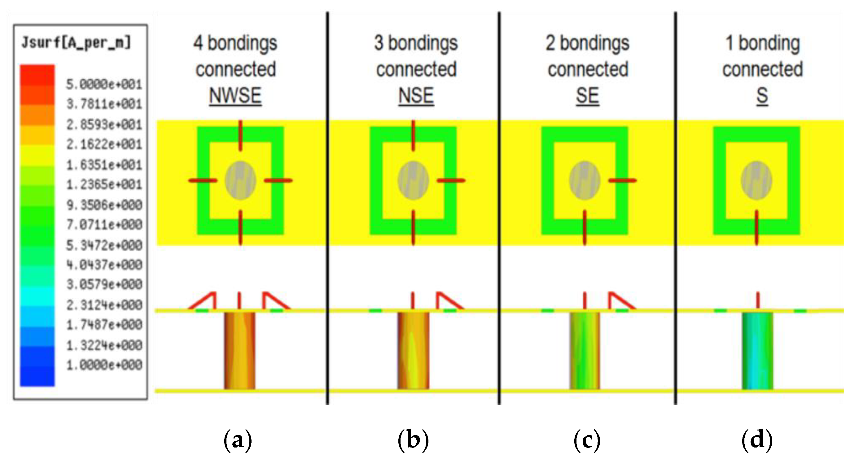
The four wire bondings shown in
Figure 1 were manually disconnected one at a time and the electrical response was measured. For consistency, the wire bondings are labeled according to their direction (
Figure 1 and
Figure 2)—N, W, S and E being North, West, South and East, respectively.
Hence, we obtained five different results beginning from the state NWSE, where all wire bondings are connected, and finishing at the state U (standing for unconnected), where no wire bonding remains.
Figure 2 illustrates the measurement results.
Assuming the state NWSE as the nominal starting state, the cavity resonated at a frequency of 11.68 GHz with all four wire bondings connected.
Table 1 summarizes measurements of the frequency shift on the transmission coefficient peak as a function of the disconnected wire bondings. The frequency shift between the two extreme states (NWSE and U) was approximately 817 MHz (Xpost = 1.9 mm). To explain this effect, the extent to which the EM field was perturbed must be considered. When the tuning post was connected with four wire bondings, a surface current was induced on the tuning post, causing a large perturbation inside the cavity.
Consequently, each time a wire bonding was disconnected (transitioning from states NWSE to NSE to SE to S to U), the induced surface current decreased, causing a smaller perturbation than the previous state until no current was induced on the tuning post, i.e., state (U).
Figure 3 shows a simulation of induced currents on a tuning post inside a cavity, as a function of the number of connected wire bondings. The induced current on the tuning post increased as the number of connected wire bondings increased. Another cavity prototype was also realized, with a tuning post at the center of the cavity (Xpost = 0 mm). The same strategy and measurements were applied as previously described, following the procedure of disconnecting wire bondings one at a time. The results, summarized in
Table 1, show that the frequency shift with the tuning post at the center was higher than when that at the edge (2910 MHz for Xpost = 0 mm). In both cases, the maximum frequency shift was obtained between configurations U and S, whereas the lowest one was between states NWSE and NSE (see
Table 1). The unloaded quality factor of this resonator varied between 440 (state NWSE) and 500 (state U) (Xpost = 1.9 mm), and was significantly better than that of standard planar resonators, e.g., stub resonators.
Consequently, there are two ways to control frequency shift, depending on the position of the tuning post and the number of connected wire bondings. The first parameter (post location on the cavity) enabled the definition of the frequency range of the tuning, whereas the second (number of wire bondings) allowed the control of the magnitude of frequency shift. However, the variation in magnitude was limited by the tuning range as defined by the position of the post.
3. Tunable Filter Design
3.1. Specifications and SIW Filter Design
In the context of communication satellite application, one possible targeted digitally tunable two-state filter should be able to discretely control a bandwidth of 250 MHz, with a central frequency ranging from 10.825 GHz to 11.075 GHz, through 250 MHz steps.
The design here of a two-state tunable filter electrically controlled using RF-MEMS fits the above specifications.
First, this required the design of a simple fourth-order Chebyshev SIW bandpass filter. SIW band-pass filters have been broadly studied in the literature [
10] and the design procedure is quite similar to that of a conventional rectangular waveguide filter. The circuit was realized on a 635 µm thick alumina substrate (εr = 9.9, tgδ = 3 × 10
−4) and was fed by a tapered microstrip line.
3.2. Implementation of Tuning Elements
The challenge then became how to make the filter tunable. So far, we have detailed our tunability solution using wire bondings. This technique was then adapted to our specifications with a combination of electrically controlled devices, using a commercial RF-MEMS switch from Radant. In comparison with a semi-conductor junction, RF-MEMS technology offers low insertion losses, near zero power consumption, large power handling and very high linearity (>60 dBm) [
11,
12,
13,
14,
15]. In [
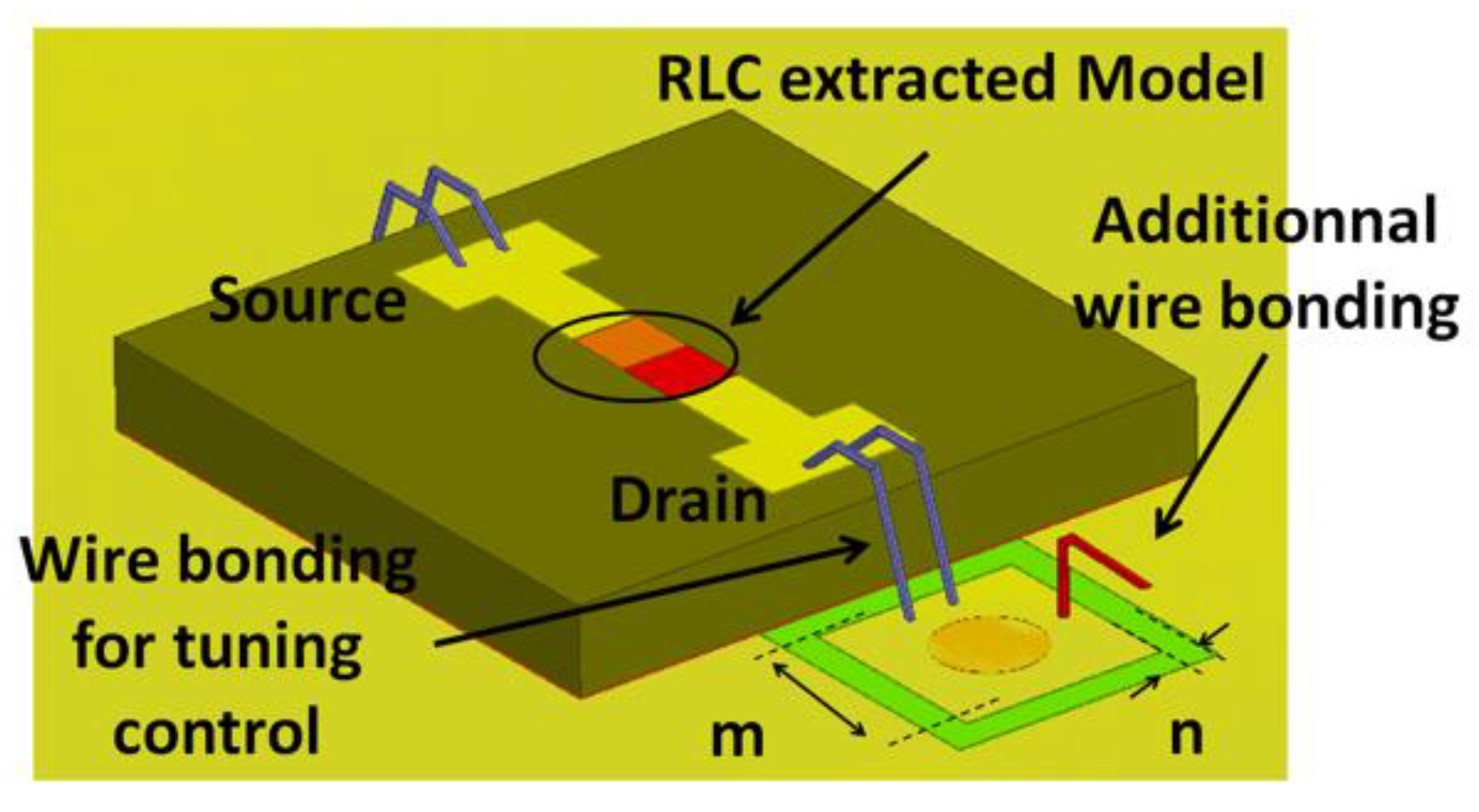
11], the authors claimed that RF-MEMS switches have a figure of merit (FOM) of ~10–20 THz, and that a comparable FOM for semiconductor technologies is 250–500 GHz, which is 20–40 times less effective than that of RF-MEMS. A 90 V actuation applied to the gate provides an electrostatic force on the RF-MEMS cantilever, allowing the RF signal to pass through the source-drain path. For high-frequency structure simulator (HFSS) purposes, RF-MEMS were modeled by a similar 3D package with an incorporated RLC Model (shown in
Figure 4) based on S-parameter data supplied by the manufacturer.
In
Table 1, the results show that there are two configurations that can be used to obtain a frequency shift close to the specifications (250 MHz): states S to SE with the tuning post at the edge (Xpost = 1.9 mm), and states NSE to NWSE with the tuning post at the center (Xpost = 0 mm). It is worth noting that the quality factor is less impacted when the tuning post is placed at the edge.
We chose to use the first configuration (Xpost = 1.9 mm). In order to command the filter electrically, it was necessary to substitute one of the two wire bondings of the SE state with the RF-MEMS switch for each cavity.
Figure 5 shows the desired configuration with the RF-MEMS switch and a wire bonding. According to Radant, the equivalent serial inductance of the two wire bondings used to connect the packaged MEMS Switch is 0.16 nH, while the parallel capacitance of the pad is 0.01 pF. The filter was designed to resonate at 10.825 GHz when the four RF-MEMS were not biased (OFF state = S state).
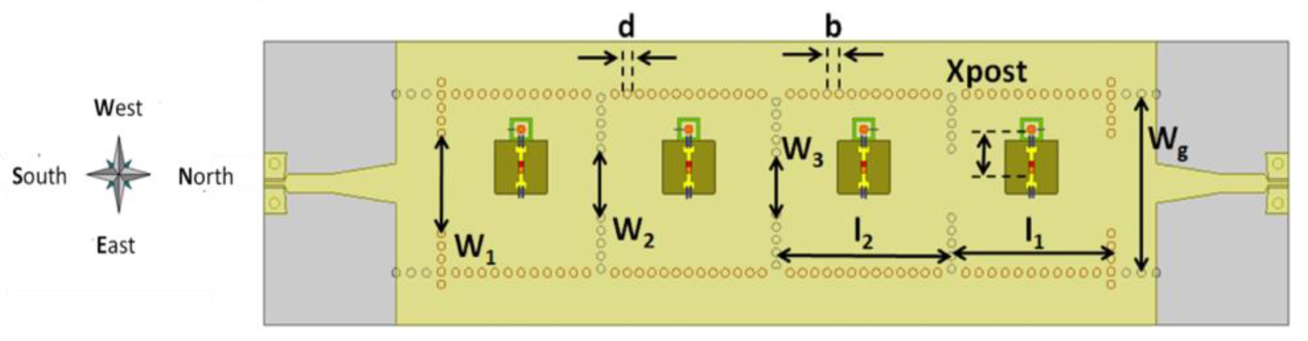
Figure 6 and
Table 2 present the top view of the tunable filter and its dimensional parameters, respectively.
4. Fabricating, Mounting and Measurements
The photograph of the realized filter is shown in
Figure 7. It was built on standard alumina substrate. Measurements were performed on a Keysight E8364 A 45 MHz-50 GHz—VNA and a Cascade Microtech summit 9000 probe station. It is worth noting the simplicity of the RF-MEMS biasing network. Indeed, a bias line was etched on the side of the filter, allowing the distribution of actuation voltage for all RF-MEMS gates through long DC wire bondings.
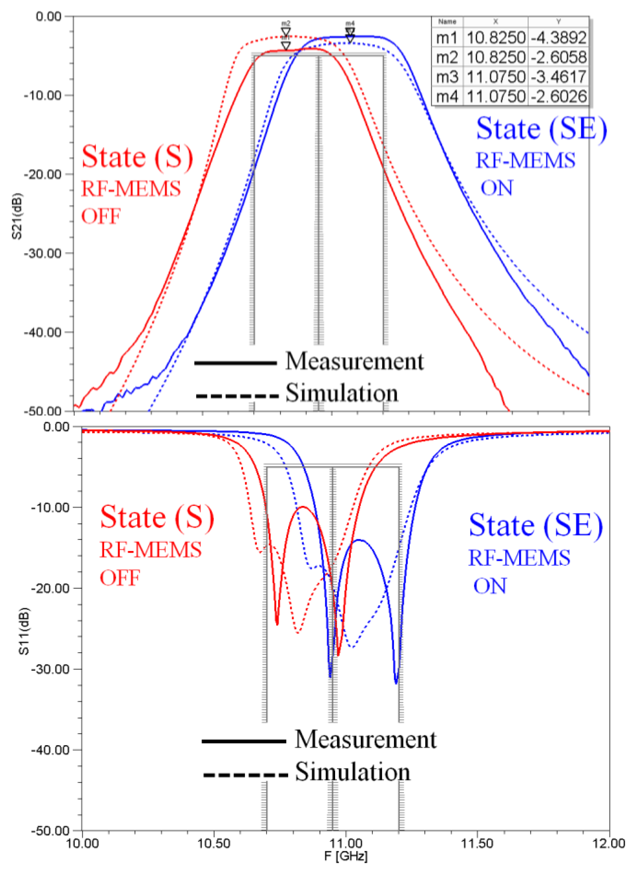
Drain and source pads were connected to the tuning post and SIW top surface, respectively. Two wire bondings were used for each connection in order to minimize the inductive effect. Moreover, a 1 MΩ resistor was mounted directly on the other side of the filter in order to limit the current. The first (OFF) and the second (ON) states were obtained for actuation voltages of 0 and 93 V, respectively. The simulated/measured responses are shown in
Figure 8.
Thanks to the four additional wire bondings (one for each RF-MEMS), the resultant tuning range between the two states was found to match the desired specifications. The center frequencies of the two states were 10.825 and 11.075 GHz, respectively. Thus, according to the specifications, we designed a tuning range of 2.3% (250 MHz). However, it seems that the model of the RF-MEMS needs to be further improved in term of losses. The measured insertion losses of the two states were 4.4 and 2.6 dB, respectively. The measured 3 dB relative bandwidths of the two states were 2.76% and 2.89%, respectively.
5. Conclusions
In this paper, we highlighted the possibility of achieving four-state digital tuning of SIW filters with the possibility to finely tune the frequencies.
Feasibility was demonstrated through the design and realization of a two-state tunable filter using commercial RF-MEMS switches. One of their remarkable advantages is the simplicity of the biasing network.
Furthermore, one major difficulty when designing tunable filter arises when attempting to master the tuning range.
In this work, the specified tuning range of the filter was set to about 2.3%, but it is possible to widen it to 24.3% by locating the tuning posts in the center of the cavities and by correctly using RF-MEMS switches and wire bondings.
Indeed, this paper also highlighted that the position of the tuning posts defined the tuning range. In the tuning range, frequency shifts between states were controlled by the number and type of switching elements.
Finally, it is possible to extend the number of states electronically addressed. For example, one solution would be to use a four-pole RF-MEMS (SP4T RF-MEMS) for each cavity, which would control the electrical connectivity in each direction (N, E, S, W) of one properly located tuning post. Thus, a specification of four targeted sub-bands could be properly addressed.

 ,
, 


