
Recent Advances in Membrane-Based Electrochemical Hydrogen Separation: A Review


1
HySA Infrastructure Centre of Competence, Faculty of Engineering, Potchefstroom Campus, North-West University, Potchefstroom 2520, South Africa
2
Centre of Excellence in Carbon Based Fuels, Faculty of Engineering, Potchefstroom Campus, School of Chemical and Minerals Engineering, North-West University, Potchefstroom 2520, South Africa
*
Authors to whom correspondence should be addressed.
Membranes 2021, 11(2), 127; https://doi.org/10.3390/membranes11020127
Submission received: 15 December 2020
/
Revised: 15 January 2021
/
Accepted: 25 January 2021
/
Published: 13 February 2021
(This article belongs to the Special Issue Polymer Membranes for Gas Separation)
Abstract
:In this paper an overview of commercial hydrogen separation technologies is given. These technologies are discussed and compared—with a detailed discussion on membrane-based technologies. An emerging and promising novel hydrogen separation technology, namely, electrochemical hydrogen separation (EHS) is reviewed in detail. EHS has many advantages over conventional separation systems (e.g., it is not energy intensive, it is environmentally-friendly with near-zero pollutants, it is known for its silent operation, and, the greatest advantage, simultaneous compression and purification can be achieved in a one-step operation). Therefore, the focus of this review is to survey open literature and research conducted to date on EHS. Current technological advances in the field of EHS that have been made are highlighted. In the conclusion, literature gaps and aspects of electrochemical hydrogen separation, that require further research, are also highlighted. Currently, the cost factor, lack of adequate understanding of the degradation mechanisms related to this technology, and the fact that certain aspects of this technology are as yet unexplored (e.g., simultaneous hydrogen separation and compression) all hinder its widespread application. In future research, some attention could be given to the aforementioned factors and emerging technologies, such as ceramic proton conductors and solid acids.
1. Introduction
The continued expansion of the commercial and industrial sectors, such as heavy-duty mobility/shipping and manufacturing, raises concerns regarding the supply capacity of existing energy resources [1,2]. Currently the global energy demand is primarily met by fossil fuel utilisation methods, which raises environmental concerns related to CO2 emissions and other greenhouse gas emissions [2,3]. Subsequently, the energy sector faces a major challenge—to decarbonise energy supply and to find new reliable, sustainable, and environmentally friendly energy alternatives [4,5]. Renewable energy (RE) is expected to play a key role in future energy systems as it is clean and sustainable [2]. However, some key challenges, such as its variable and intermittent nature [3,6,7] remain to be addressed before completely transitioning towards RE [2]. The solution to this problem lies in adequate large-scale energy storage, which would increase energy supply reliability [8]. Energy storage can provide energy flexibility and will reduce the global dependence on fossil fuel backup power. Various types of energy storage systems exist [6,9,10]. These can be broadly categorized [8] as electrochemical (batteries) [11], chemical (hydrogen systems: Fuel cells/electrolyses [12,13,14]), electrical (capacitors, super capacitors and ultra-capacitors) [15,16], mechanical (flywheels [17,18,19], compressed air [20,21] and pumped hydro-storage [22,23]) and thermal (hot water, sensible/latent heat storage, solar energy storage) [24,25,26,27,28], and magnetic (superconducting energy storage) [29]. Alternative methods for large-scale energy storage are being researched, including renewable hydrogen and synthetic natural gas [6].
Hydrogen is part of an industrial concept known as power-to-gas (P2G) technology, which is a power grid balancing mechanism used to capture and store surplus energy to use at times of limited supply (e.g., night-time or at times of low wind speed when solar and wind is used as energy source) [7]. In principle, P2G converts excess RE into a chemical carrier such as hydrogen or methane [7]. Hydrogen, in particular, is attracting great interest as an energy carrier, with many unique properties to commend itself [30,31]. It can be produced/converted into electricity by means of electrochemical devices (e.g., electrolysers and fuel cells) with relatively high energy conversion efficiencies and can be stored using a variety of methods [3,31,32,33,34,35], such as compressed gas, cryogenic liquid [36,37], chemical compounds (e.g., liquid organic hydrogen carriers (LOHC) [38,39,40], ammonia) [41] or it can be adsorbed/absorbed on special materials (e.g., metal hybrids [42], chemical hybrids, carbon nanostructures). Long-distance hydrogen transportation can be achieved through pipelines [43,44] or via tanker trucks [45], and can be converted into various forms of energy more efficiently than other fuels [30,31]. Furthermore, hydrogen can be generated in an environmentally friendly manner with no greenhouse gas pollutants [30,31]. Hydrogen also has potential to provide energy to the main sectors of the economy, including transportation, buildings, and industry [46,47]. This, in turn, may lead to a low-carbon energy system known as the “hydrogen economy”, which was introduced in 1972 [48].
Currently, hydrogen is a very important industrial commodity, as it is a key reactant and/or by-product of several industrial processes, including the food industry, petrochemical and petroleum refining, ammonia production, methanol production, hydrogenation processes, hydrometallurgical processes, and metal refining (mainly nickel, tungsten, molybdenum, copper, zinc, uranium, and lead) [3,46,49,50,51]. It can also be employed for application in electricity production from fuel cells, transportation, and energy storage [51].
Hydrogen is not widely available in gaseous state, but rather in a form of chemical compounds in natural sources, such as natural gas, water, coal and biomass (after gasification), which are all major feedstocks for hydrogen production [52]. Many hydrogen production pathways can be found in literature [45,53,54,55] and the selection thereof is mainly dependent on the feedstock used to produce hydrogen, the scale of production, and the available energy sources [2]. These pathways can be classified in various ways: The hydrogen source/feedstock (hydrocarbons or non-hydrocarbons) [2,3,56,57], the chemical nature and/or energy input [2,3,56] (thermochemical, electrochemical and biological [46]), the production method used [3,52,56,57] (its maturity level and efficiency) [2], the catalyst material [52], storage [51], the distribution mechanism (i.e., on-site generation or delivered) [53,56] and end use (e.g., hydrogen purity required) [50]. The choice of the hydrogen production pathway should take into account, (i) the hydrogen fuel quality grade required for end-use application and (ii) purification technology feasibility [2]. Separation processes, such as pressure swing adsorption (PSA), are applied to improve the economics of the conventional hydrogen production methods [58].
Table 1 summarizes the state-of-the-art hydrogen production technologies based on their advantages and disadvantaged, the technology maturity level (TML), the process efficiency, cleanness of the hydrogen, and the impurities commonly contained in the product streams [2].
For hydrogen production, fossil fuels are currently the main source [59]. Fossil fuel-based hydrogen production technologies are already developed and mature industrial technologies [60], capable of producing high grade hydrogen at relatively lower costs compared to some alternatives [59]. Therefore, of the over 50 million tons of hydrogen produced annually, fossil fuel-based hydrogen production constitutes an estimated 95% [3,61]. There are a number of feedstocks used to produce industrial hydrogen, but the most favoured feedstock is natural gas due to it being abundantly available and cost efficient [52,62].
The two main methods used in industry to produce hydrogen from fossil fuels are reforming processes and gasification [53]. These two methods are distinguished by the nature of the incoming fuel [3]. Gasification processes use solid fuel, such as coal, biomass and solid waste to produce hydrogen or syngas (a mixture of mainly H2, CO [63] and, in some instances, CO2 [46,64,65]), while reforming processes make use of fluid fuel, either in gas or liquid form, for syngas production [3]. Three reforming processes can be differentiated to produce hydrogen from hydrocarbons: (i) Steam reforming (particularly steam methane reforming (SMR)) [55,61,65,66,67,68], (ii) partial oxidation (POX) [3,46,66], and (iii) auto-thermal reforming (ATR) [3,55,65]. These processes are distinguished by the reactants involved and the thermodynamic nature of the reactions taking place [3,55]. For example, in SMR and steam-gasification, steam (water) reacts with hydrocarbons to produce hydrogen. This reaction is endothermic. In the case of POX and gasification, oxygen reacts with the hydrocarbons to produce hydrogen and results in an exothermic reaction. When these two reactions are combined (SMR and POX), the process is termed as ATR [3,55,67]. In addition to H2, CO2 and CO are emitted by reforming processes [46,65]. Other hydrogen reforming technologies can also be found in literature, such as hydrocarbon pyrolysis, plasma reforming, ammonia reforming and aqueous phase reforming [67,69]; however, they are not as common as SMR and coal gasification. In the majority of the processes listed above, CO2 and/or CO is produced. One of the promising technologies that receive significant attention is the utilization of CO2 by reacting it with H2 to produce valuable chemicals, such as methane and methanol (e.g., through the Sabatier process) [70,71,72,73]. Similarly, CO can be converted through the water–gas shift (WGS) reaction [3,55,60,67,74].
Although fossil fuels are currently the main feedstock used to produce hydrogen, renewable integrated technologies are unavoidable for the global energy future [67]. Several processes have been proposed for hydrogen production from renewables [87]. Though not widely implemented, hydrogen can be produced from biomass using processes such as pyrolysis/gasification, but this is commonly accompanied by large amounts of impurities [31,61,65,66,88]. Several methods of hydrogen production from water are also available, including electrolysis, thermochemical processes, photolysis, and direct thermal decomposition or thermolysis [61]. Water electrolysis is a common method used to produce hydrogen; furthermore, it is the only method, at present, that can be used for large-scale hydrogen production without fossil fuel utilization [31]. One major advantage of water electrolysis is that no-carbon containing compounds are present in the exhaust, only water [2,66,67]. Hydrogen is obtained by splitting water into oxygen and hydrogen, achieved by an electrical current [89]. The electricity required for electrolysis can be generated from renewable sources (e.g., solar, wind and hydropower) or non-renewable sources (fossil fuel or nuclear-based) [90].
The benefits of hydrogen as a fuel, which is clean and efficient, can only be fully recognized when hydrogen is produced from renewable energy sources [6]. Most of the current hydrogen production methods yield hydrogen-rich streams, but are commonly accompanied by contaminant gases including CO2, CO, sulphur-containing components, CH4, and N2 (see Table 1). Shalygin et al. [91] gives a detailed composition of all small to large-scale hydrogen production process streams. High-purity hydrogen (>99.97%) is required for fuel cells (according to SAE J2719—see Table 2), the chemical industry and stationary power production. The hydrogen produced from commercial processes should, therefore be purified after production, based on end-use application, e.g., fuel cells.
The purpose of this review is twofold: (i) To provide a general overview and comparison of the commercially available hydrogen separation technologies, and (ii) to survey open literature, on the status, and advances made, in the field of electrochemical hydrogen separation (EHS). With the former, special emphasis is given to membrane technologies, especially the membrane materials/types and their performance properties. With the latter, all available literature on EHS are summarized and classified based on the type of article (experimental, modelling, case study or review) and the year it has been published, the operating temperature range, the membrane materials, the type of electrocatalyst and the type of impurities contained in the feed. In the conclusion, literature gaps in the field of EHS is identified for further (future) research.
2. Hydrogen Separation/Purification Technologies
For hydrogen to be realized as a widespread energy carrier (especially as a carrier of RE), its purification and compression are unavoidable industrial processes. Several technological approaches are used to extract hydrogen from gas mixtures, utilizing various characteristics of hydrogen, under different industrial conditions. Common approaches for hydrogen recovery include the following: Adsorbing the impurities (pressure swing adsorption, PSA), condensing the impurities (cryogenic distillation) or by using permselective membranes [49,92,93]. Although PSA and cryogenic distillation processes are both commercial processes used in hydrogen separation, pressure-driven membranes are considered a better candidate for hydrogen production because they are not as energy intensive and they yield high-purity hydrogen [92]. Moreover, PSA and cryogenic distillation technologies all require multiple units and, in some instances, may involve supplementary wash columns to remove CO and CO2 [49]. Additional advantages offered by membrane technologies include the ease of operation, low energy consumption, possibility of continuous operation, cost effectiveness, low maintenance and compactness [86,92,94,95,96]. Nonetheless, despite their numerous advantages, membrane systems commonly depend on high-pressure feed streams and hydrogen embrittlement is often experienced [49]. As a rule, hydrogen appears in the permeate (low pressure stream after membrane), and additional compression is required after hydrogen purification for transport and storage purposes [97]—including expenses of energy, additional equipment, etc. Properties of the various hydrogen purification technologies are summarized in Table 3. A brief discussion of each technology then follows.
2.1. Pressure Swing Adsorption
PSA is the most extensively used state-of-the-art industrial process for hydrogen separation [100]; it is capable of yielding hydrogen with a purity ranging from 98–99.999% [2,81,97]. It is most frequently used in the chemical/petrochemical industry, as well as to recover hydrogen from industrial-rich exhaust gases, including reforming off-gases, coke oven gases, and pyrolysis effluent gases [92,94,101]. Currently, about 85% of the produced hydrogen is purified by PSA [102]. Although the system is mainly classified as a batch system, continuous operation can be achieved by implementing multiple adsorbers [92,93,94], creating a cyclic process [103,104]. The system can be divided into five primary steps: (i) Adsorption, (ii) concurrent depressurization, (iii) counter-current depressurization, (iv) purge and (v) counter-current pressurization [94,100].
In PSA, a hydrogen-rich gas mixture is passed through a high-surface-area adsorber, capable of adsorbing the impurities (e.g., CO, CO2, CH4, H2O and N2 [105]), whilst allowing hydrogen to permeate through the material [103]. The impurities are removed by swinging the system pressure from the feed to the exhaust pressure, coupled with a high-purity hydrogen purge. The driving force of PSA is the difference in the impurities’ gases’ partial pressure of the feed gas and the exhaust. Generally, hydrogen separation requires a pressure ratio of 4:1 between the feed and the exhaust [103]. In the initial layer H2O, CO2 and CH4 is removed, whilst a second layer removes other components until the levels of CO is <10 ppm [105]. The reaction takes place at room temperature and at pressures of 20–25 bar [104]. Zeolites are commonly used as adsorbent materials [103]. To increase the hydrogen recovery, a complex arrangement of the columns is required; generally, more than eight columns are required [105]. The quantity of recovered hydrogen is dependent on the feed and purge gas pressures and hydrogen-to-impurity ratio [92]. The hydrogen recovery is typically in the range between 60% and 90% [97].
2.2. Cryogenic Distillation
Cryogenic distillation is a widely used separation process at low temperature (LT). It is used to separate gas components based on differences in their boiling temperatures [92,93,94]. Hydrogen’s low boiling point of −252.9 °C (below that of almost all other substances) is used as a measure to separate it from other components, where the collected hydrogen can be stored as a liquid [106]. The gas needs to be cooled down, to condense, resulting in large energy consumption [92,94].
If significant amounts of CO, CO2 and N2 are found in the feed stream, a methane wash column is required to reduce the concentrations of these gases [92,93]. The feed gas also requires pretreatment to remove the components that might freeze; therefore, water should be reduced to <1 ppm and CO2 to <100 ppm [94]. It is not practical to use this method to obtain high-purity hydrogen, however, higher hydrogen recovery can be achieved at moderate hydrogen purity yields (≤95%) [92,94]. Similar to PSA, cryogenic distillation is perfect for large industrial scales, but unsuitable for small portable applications [103].
2.3. Membrane Technologies
Besides PSA and cryogenic distillation, membrane separation has attracted the widest interest. A membrane is a selective barrier between two phases [107] that allows mass transfer under the action of a driving force [108] (e.g., gradients in pressure, temperature, concentration or electrical potential [107]). This allows for preferential permeation of some components of the feed stream, with retention of the other components [109]. See Figure 1.
Membranes for hydrogen separation can be divided into organic (polymeric), inorganic and mixed-matrix (hybrid). See membrane classification scheme in Figure 2, which is based on the nature of the material of the membranes. Currently, industrial processes mainly use polymer membranes (glassy or rubbery [110]) due to their capability to cope with high pressure drops, their low cost and good scalability [108]. Though organic/polymeric membranes are temperature limited (363–373 K) [108,111], recent progress have been made with thermally rearranged polymers—which show good separation at high temperatures [112,113]. Inorganic membranes provide several advantages, including mechanical, thermal and chemical stability [114], it’s typically not subject to dimensional changes, such as plasticization, or swelling of the membrane upon adsorption of the components of the feed gas and controllable pore size distribution allowing for better control over selectivity and permeability [108]. To take advantage of the capabilities of inorganic membranes combined with the low manufacturing costs of the organic membranes, mixed-matrix membranes have been developed (composite materials that consist of continuous polymeric matrix and imbedded, mainly inorganic, particles) [115]. According to their characteristics, membranes can be classified as either dense (non-porous) or porous [92,96]. Porous membranes can be divided into glasses, organic polymer, ceramic- and carbon-based membranes (carbon molecular sieves) [116]. A particular important type of membranes is metallic or metal-alloys membranes (mainly Pd and/or its alloys [110]). Ceramic proton-conducting membranes are also known, but are still at the earlier development stage [108]. According to the IUPAC classification of pores sizes, porous membranes can be either microporous (dp < 2 nm), mesoporous (2< dp < 50 nm), or macroporous (dp > 50 nm), where dp is the average pore diameter [108].
Gas transport through membranes can occur through a number of mechanisms [109]. A comprehensive review of the permeation mechanisms of inorganic membranes can be found in Oyama et al. [117]. Porous membranes achieve fractionation based on differences in size, shape and/or affinity between the permeating molecules and the membrane [108]. Depending on the pore size, different mechanisms will dominate molecular transport [118]. Mechanisms associated with porous membranes include, broadly: (i) Knudsen diffusion, (ii) surface diffusion, (iii) capillary condensation and (iv) molecular sieving (MS) [79,92,103,109,119]. See Figure 3. MS is an activated process that will be dominant for the smallest pores (pore diameter and diameter of diffusing molecules are approximately the same). Whereas surface diffusion will dominate the some somewhat larger pores, and Knudsen diffusion will dominate the even larger pores [118]. Separation based on Knudsen diffusion is mainly determined by the pore size and it occurs when the pore diameter of the membrane is smaller than the mean free path of the gas being separated [107]. Separation based on MS operate on size-exclusion principal [92]. In other words, only molecules with small enough kinetic diameters can permeate through the membrane [103]. Separation based on capillary condensation takes place when a partially condensed gas phase occupies a pore. Only gases that are soluble in this condensed phase can permeate through the pores when the pores are completely filled [103]. Surface diffusion can occur alongside Knudson diffusion. It involves the adsorption of gas molecules onto the pore walls of the membrane and spread along the surface [92,103]. Permeability will be high for the molecules that are readily adsorbed onto the pore walls. However, this form of diffusion is limited to certain temperatures and pore diameters [103]. In the case of dense membranes, molecular transport occurs through a solution–diffusion (Sol–D) mechanism [120]. Thus, for the separation of hydrogen from other components in a gas mixture, both size (diffusivity) and the condensability (solubility) of the gases to be separated play important roles [92,108,111,120,121].
Hydrogen purification typically involves the separation of H2 from light gas molecules, such as CO2, CO, CH4, H2O and impurities, e.g., H2S. Physical adsorption becomes negligible at temperatures >400 °C, therefore hydrogen separation is mainly based on MS (hydrogen kinetic diameter = 2.89 Å) and differences in molecular diffusivity [114,122]. Gas transport through non-porous metals (Pd) involves dissociation of H2 molecules into atomic hydrogen and its transport through the films [123]. Knudsen diffusion or a combination of Knudsen diffusion and surface diffusion are characteristic for porous metal membranes, e.g., porous stainless steel [124,125]. Likewise, hydrogen transport through ceramic membranes is based on Sol–D (dense ceramic) and MS (microporous). Gas transport in polymeric membranes and carbon membranes, on the other hand, occurs based on the Sol–D mechanism and MS, respectively. The kinetic diameters of light gases commonly found in produced H2 streams, such as He, H2, NO, CO2, Ar, O2, N2, CO and CH4, can be found in Teplyakov and Meares [126] and Nenoff et al. [127].
Two basic properties are used to evaluate the performance of a membrane: Permeance (also commonly referred to as the flux or permeation rate [107]) and selectivity [92,108,109,111]. The higher the selectivity, the lower the driving force required to achieve a certain separation—thereby reducing the cost of operation of the system. Conversely, the higher the flux, the smaller the required membrane area—thereby reducing the capital cost of the system [111]. Permeance is defined as the net transport of constituents through the membrane and it can be expressed as either mass per unit time and unit area, or mole per unit time and unit area [79]. It is usually used to assess the permeability for composite and asymmetric membranes [109]. The permeance in mol·m−2·s−1·Pa−1 (SI) (or cm3(STP)·cm−2·s−1·cm−1 Hg)), is the permeability coefficient Pi divided by the membrane thickness (cm, or sometimes reported in m) [92,117,128]:
Permeability coefficient, or permeability, is typically used to define the membrane’s capacity to perform gas transport. In other words, permeability is the measure of the ability of certain gas components to diffuse through a membrane [103], where high permeability indicates a high throughput [111]. It denotes the amount of hydrogen (molar/volume) diffusing through the membrane per unit area and time at a given pressure gradient [103,111]. Several units are commonly used for permeability, including Barrer (10−10 cm3(STP)·cm·cm−2·s−1·cm−1 Hg = 3.347 × 10⁻¹⁶ mol·m−1·s−1·Pa−1 (SI units)), gas permeability units (GPU = 10−6 cm3(STP)·cm−2·s−1·cm−1 Hg) or molar permeability (mol·m·m−2·s−1·Pa−1) for characterization of the permeance of membranes.
The selectivity of a membrane measures the membrane’s ability to separate a desired component from the feed mixture [108]. Membrane selectivity towards gas mixtures and mixtures of organic liquids is usually expressed by a separation factor α. The ideal selectivity/permselectivity [111] is defined as the permeability or permeance ratio of two pure gases:
where, Pi and Pj, and Qi and Qj are the permeability coefficients and permeance as gases i and j, respectively.
Typically, the more permeable gas is taken as i, so that αi/j >1 [129]. Ideal selectivity is very useful for the description of the separation of mixtures of light gases, such as H2 and N2, which have low solubility in membrane materials. Thus, the gases only weakly affect the property and behaviour of the polymer, they do not affect the mutual diffusion and sorption parameters in the process of simultaneous transport of gases in mixture separation [128]. Whereas, in the case of heavy vapours/gasses with great solubility, the applicability of this parameter is not as predictable [128]. The following equation is used for mixture separation [128]:
where, yi and yj depict the concentration of components i and j in the permeate. Mass and molar concentrations (kg.m−3; mol·m−3), as well as weight fraction, mole fraction, and volume fraction are frequently used. As for xi and xj, two definitions are found in literature and are considered. According to Koros et al. [130], if xi and xj characterize the composition of the feed stream, this ratio (Equation (3) is termed the separation coefficient, similarly, if xi and xj refer to the composition in the retentate, the ratio is termed the separation factor [128]. The former is also sometimes referred to as the ideal/“actual” selectivity [107]. If αA/B = αB/A = 1, no separation is achieved [107]. In the case where the feed pressure is significantly larger than the permeate pressure, and the permeate pressure approaches zero, the ideal selectivity and real selectivity will be in equal [109].
A fundamental expression for transport in membranes is derived from Fick’s first law, which relates the flux of species i to the concentration gradient. Under steady state conditions, this equation can be integrated to give:
where, Ji is the flux (cm3(STP)·cm−2·s−1 or mol·m−2·s−1), Di is the diffusion coefficient (m2·s−1), Ci,0 and Ci,δ depicts the inlet and outlet concentrations (usually mol·m3), and δ is the membrane thickness (m) [98,131].
2.3.1. Porous Membranes
The transport mechanism for each mechanism (porous membranes) can be summarized as follows [118,132]. The molar flux through the pores can be defined by Fick’s law Equation (4). According to Burggraaf et al. [133] and Bhandarkar et al. [134], the Fickian diffusion coefficient (Di) is composed of a corrected diffusion coefficient together with a thermodynamic correction factor Γ(T,P):
The diffusion coefficients are defined as:
where, Ea denotes the activation energy (kJ·mol−1), R is the universal gas constant and T is the temperature (K). Different methods for obtaining DK,c have been reported [98,117].
If ideal gas behaviour is assumed, Γ = 1 and Equations (4) and (7) can be combined and integrated to give:
where, δ is the thickness of the membrane and is the difference in the outlet and inlet partial pressures. Similarly, the integrated flux equations for activated processes, assuming Henry’s law for adsorption, can be written as [132,133,135]:
where, Eads denotes the adsorption energy (kJ·mol−1).
Substituting these expressions into the flux equation and defining the permeability, Pi, and permeance, Qi, due to a particular transport mechanism as the following temperature dependencies for the permeance due to the transport mechanism are obtained:
In the case of Knudsen diffusion, the selectivity can be calculated using Equation (15) [111]:
2.3.2. Dense (Non-Porous) Membranes-Diffusion Mechanism
Solid-state diffusion occurs with a further decrease in the pore size, where the gas molecules interact strongly with the membrane material and its solubility needs to be considered [117]. In this case, the permeability can be determined using the equation that is based on the sol-D model [103,107]:
where, S is the gas solubility in mol·m−3·Pa−1 (see Equation (23)). If Equation (16) is substituted into Equation (2), it is possible to speak of selectivity of diffusion and sorption [128]:
There are three instances where this transport mechanism applies: (i) permeation through glassy membranes, (ii) metallic membranes, and (iii) polymeric membranes [117,136]. Overall, the permeability can be calculated using the following expression [98,128]:
Steady-state flux of gases through a dense (non-porous) metallic membranes can be expressed by Equation (1) [137], which is derived by combining Fick’s first law (driving force = concentration gradient) (Equation (4) [107,138] and Henry’s law (Equation (20) [139]), as follows:
where, Ji is the flow rate (mol·m−2) of the diffusing species, Pi is the permeability coefficient (mol·m−1·s−1·Pa−1) of component i, δ is the thickness of the membrane (m), and and are the hydrogen partial pressures at the feed and permeate side, respectively. Furthermore, Si and Ci, refers to the solubility coefficient (mol·m−3·Pa−1), and the concentration gradient across the membrane, respectively. The pressure component (n) is generally in the range of 0.5–1, depending on the limiting step of the hydrogen permeation mechanism [108,117,139]. The hydrogen permeation is controlled by the rates of adsorption/desorption and the diffusion through the lattice [117,140]. Generally, if diffusion through the metal is the rate limiting step, the pressure is relatively low, and the hydrogen atoms form an ideal solution in the metal, then n = 0.5 known as Sievert’s law [108,111]. Higher values of n are expected when mass transport to/from the surface or dissociative/associative adsorption steps become rate determining [108]. Moreover n > 0.5 for defective membranes (e.g., pinhole formation) or when the rate is influenced by the membrane’s porous support [108]. Furthermore, the thickness of the membrane can also influence the value of n, causing it to be >0.5 [141].
The relationship between the permeability and temperature follows Arrhenius behaviour [142]:
where, is the maximum permeability at infinitely high temperature, is the activation energy for permeation, R is the universal gas constant, and T the absolute temperature. Similarly, the temperature dependence of the gas diffusion coefficient and solution coefficient can be expressed as follows (Equations (22) and (23)) [121]:
where, Ed is the activation energy of diffusion, ΔHs is the partial molar sorption, D0 and S0 are the diffusivity and solubility, respectively, at infinite temperature [103]. Consequently, when n is 0.5, the flux can be written in terms of the so-called Richardson equation, where Equation (21) is substituted into Equation (19), as follows:
2.3.3. Ceramic Proton-Conducting Membranes
Although proton-conducting ceramics are still at the early stages of development, several research efforts have been made [143,144,145,146,147,148,149,150]. Overall, the process of hydrogen permeation through a dense proton conducting membrane involves several steps [122,151]:
- H2 gas diffusion to reaction sites on the surface of the feed side;
- H2 adsorption, dissociation, and charge transfer at the membrane surface;
- Proton reduction and hydrogen re-association at the membrane surfacewhere, S’, BM, S” and G is the membrane surface at the inlet, the bulk membrane, the membrane surface at the outlet, and the gas, respectively.
Two transport mechanisms have been proposed in literature: The vehicle mechanism and the Grotthus/proton hopping mechanism [151]. In the vehicle mechanism, protons bind to oxygen to form a hydroxide ion which diffuses through the lattice by vacancy or interstitial diffusion. Electroneutrality is achieved through the counter-diffusion of unprotonated vehicles or oxygen vacancies [108]. The Grotthuss mechanism instead assumes that protons jump between stationary oxygen ions, and that the diffusion of protons and electrons occur in the same direction, whilst maintaining electroneutrality and a zero net electric current [151,152]. For structural reasons, proton transport in oxides is better explained by the Grotthuss mechanism [153].
The proton flux (mol·cm−2·s−1) for a membrane containing only protonic-electronic conductors can be described by the Wagner equation [108,154]:
where, R is the universal gas constant (8.314 J·mol−1·K−1), T(K) is the absolute temperature, F is the Faraday constant (96 485 C·mol−1), δ is the thickness of the ceramic membrane (m), (S·cm−1) is the proton conductivity within the membrane, is the electronic transport number, and is the hydrogen partial pressure (Pa). In this equation, the pressure gradient serves as driving force and the flux is directed from I [108]. Since and can be dependent on the pressure, Norby and Haugsrud [152] and Marie-Laure et al. [153] integrated Equation (20) for different limiting cases. For example, when and is proportional to where (i) n = 0.5 when protons are minority defects, (ii) n = 0.25 when protons are majority defects compensated by electrons, and (iii) n = 0 when protons are majority defects compensated by acceptor dopants. In (i) and (ii), and, therefore, the partial pressure on the feed side (I) has a strong effect on the proton flux. In case (iii), , and consequently the pressure on both sides are equally important [108,152].
A comparison of membrane properties, such as the temperature range, hydrogen selectivity and flux, and stability and poisoning issues are summarized in refs [79,92,103,155]. A more detailed quantification of hydrogen flux and selectivity for polymeric membranes can also be found in the following references [79,91,92,103,128,130,155]. Dense metal membranes (mainly palladium alloys) are seen as the most appropriate construction materials due to their high hydrogen selectivity [92,94,123,155]. However, Pt- and Pd-based membranes are known to have a high sensitivity to a variety of surface contaminants, such as H2S, CO, thiophene, chlorine and iodine [79]. These contaminants severely influence the performance of these membranes [79]. This is explained by the favourable interaction between the membrane and the contaminants. Membrane degradation/hydrogen embrittlement is also a common issue in metal membranes with high diffusivity or solubility (e.g., Pd-membranes) [140], which make them less durable. However, the problem of hydrogen embrittlement in Pd-based can be minimized by alloying the membranes [140] or by controlling the operating conditions to avoid a two-phased region [156]. Besides dense metallic membranes, dense ceramic membranes are also seen as a favourable option for hydrogen separation, for the same reason [155].
3. Electrochemical Hydrogen Separation
Electrochemical membranes are seen as a promising alternative to pressure-driven membranes [94]. Electrochemical membranes are known to generate electricity (fuel cells) or to apply it (water electrolysis), and they are also used to purify/enrich and compress hydrogen streams [94]. EHS has the following advantages over other conventional separation systems [157,158]:
- Hydrogen, in the form of protons, is selectively transferred through the proton-conducting electrolyte;
- one-step operation provides pure hydrogen;
- the hydrogen separation rate can be controlled by the current (Faraday’s Law);
- a high hydrogen collection rate is achieved;
- simultaneous purification and compression of hydrogen is possible, in principle;
- high hydrogen separation is achieved at low cell voltages, with a high separation efficiency [156] and
- high selectivity and low permeability results in pure hydrogen (up to 99.99 vol.%) [159].
An additional benefit of this method is that CO2 is concentrated, and it can be captured and stored, without any further treatment—hence reducing greenhouse gas emissions [156,160]. In terms of application, electrochemical hydrogen separation could be beneficial in numerous industrial fields, including: (i) Hydrogen purification, for the use in fuel cell technologies, (ii) cooling agent in turbines, (iii) for the application in nuclear reactors (separation and concentration of hydrogen isotopes) and (iv) separation of hydrogen from natural gas mixtures (e.g., transportation of hythane through gas pipelines) [161]. Furthermore, compressed high-purity hydrogen is required for fuel cells (>99.97%) (SAE International, 2015) and hydrogen mobility (e.g., Hydrogen Mobility Europe (H2ME) [162,163]).
3.1. Working Principle
In principal, EHS is based on the following process (Figure 4). Molecular gaseous hydrogen (or a gas hydrogen-containing gas mixture) is injected at low pressure at the anode side of the proton exchange membrane (PEM) electrochemical cell. When the hydrogen makes contact with the anode electrode, hydrogen is oxidized into its constituents (protons and electrons), achieved with a Pt-based catalyst (Equation (26). The electrons then travel through an electrical circuit, whilst the protons move through the PEM to the cathode compartment. Finally, the protons and electron reduce to H2, at the cathode compartment (Equation (27). This can be carried out at high pressure to improve the specific volumetric energy density, for storage.
In the case of hydrogen purification and separation, a hydrogen-rich gas enters the anode compartment and hydrogen is selectively transferred through the PEM. This reaction does not occur spontaneously. An external voltage (DC power source) is required to drive the chemical reaction (electrolytic mode) [164]. According to literature, minimal power is required to operate the cell [49]. The oxidation and reduction reactions of hydrogen are facile and corresponds to Nernstian/Faradic theoretical values in their electrochemical behaviour [49].
Unlike conventional membrane systems that rely on pressure or concentration differentials, the hydrogen permeation of an electrochemical hydrogen separator is only dependent on the applied current as driving force, which is quantified by the law of Faraday:
where, depicts the flow of hydrogen (mol·s−1), is the current (A), depicts the number of electrons, and is Faraday’s constant (96, 485 C·mol−1). Faraday’s law can also be rewritten in terms of the hydrogen mass flow rate (), which is proportional to the current [165]:
where, M is the molecular weight in kg·mol−1.
Although the cell overvoltage in this process is normally quite low, high hydrogen separation efficiencies can be achieved [156]. The purity of the hydrogen that is produced at the cathode side is high. This is highly dependent on several factors, for example: (i) The permeability of the membrane with respect to the feed gas composition, (ii) the integrity of the membrane and (iii) in the case of LT gas separation (<100 °C), when Nafion is used, the water content of the membrane [49].
3.2. Current Status of Electrochemical Hydrogen Separation Technology
A summary of previously reported literature on electrochemical hydrogen separation technologies is presented in Table 4 (in chronological order). The type of article, membrane, and electro-catalyst, as well as the gas mixtures that was used in the listed articles are included. A brief discussion on each contribution follows. The articles are characterized as high-temperature and low-temperature, with subsections “active” and “passive” gas mixtures. “Active” gas mixtures in this paper refer to gases that have affinity to either the membrane or the catalyst, e.g., CO and Pt catalyst. “Passive” gasses refer to gas mixtures that do not react with the membrane or the catalyst, typically made of permanent gases, such as N2 and Ar.
3.2.1. Low-Temperature EHS
“Passive” Gas Mixtures
- H2/CH4 Mixtures
Ibeh et al. [168] investigated hydrogen separation from H2/CH4 mixtures with both Pt and Pt-Ru catalysts. Results indicated that little energy was consumed and CH4 seemed to be inert at LTs, hence resulting in negligible fouling of the anode electrocatalyst. Moreover, it was found that if the hydrogen recovery is <80%, a small portion of the hydrogen energy is required for separation. A mathematical model was developed to simulate the electrochemical separation process. The model was adapted from the model used by Zhang [189]. This model takes into account the hydrogen adsorption and oxidation reaction, together with their reaction rates. Also, differential equations were used and solved using the ODE solver in Scilab. The differential equation included: The time dependence of the hydrogen surface coverage, the material balance for species i, the variation of the hydrogen pressure in the anode chamber, and the time dependence of the anode potential. There was a good agreement between the experimental data recorded and the simulated results.
- H2/Ar Mixtures
Nguyen et al. [159] used electrochemical impedance spectroscopy (EIS) to characterise and measure the kinetics and efficiency of the PEM and electrochemical cell. The roles of the cell structure and the different operating parameters (cell temperature, relative humidity and the partial pressure of hydrogen) on the overall process efficiency were investigated. Both the cell conductivity and electrode activity were measured. The relative humidity played a key role in the performance of the cell; the best performance (lowest membrane electrode assembly (MEA) resistance) were recorded when the cell and gas humidifier temperatures were similar, and close to 70 °C. Under these conditions, catalytic layers showed the highest activity. Consequently, lower catalyst activity was recorded at lower temperatures. Furthermore, when the humidifier and cell temperature difference was >10 °C, the water content for membrane humidification decreased, resulting in high MEA resistance. Moreover, mass-transport limitations were observed when the hydrogen partial pressure of the feed decreased. They concluded that an electrochemical hydrogen pump is limited to the treatment of gases in which the hydrogen content is >50%.
- H2/N2 Mixtures
Casati et al. [170] investigated the concentration of hydrogen achieved electrochemically from a lean hydrogen-inert gas mixture under galvanostatic and potentiostatic conditions. Results of the experimental runs suggested that galvanostatic operating conditions were unstable, whereas operation at potentiostatic conditions appears to be more stable. They reported that the hydrogen recovery increased with applied potential and the coefficient of performance (defined as the ratio of the hydrogen produced over the hydrogen consumed) decreased with the applied potential difference. Furthermore, the feed flow rate had a noteworthy effect on the recovered hydrogen. They proposed an optimum energy efficiency for separation, but did not identify its dependency on the process parameters.
The current efficiencies for current densities between 0 and 2 A·cm−2 were >83% and >90% for current densities ≥0.4 A·cm−2. Premixed natural gas reformate (35.8% H2, 1906 ppm CO, and 11.9% CO2, with the balance N2) and methanol reformate (1.03% CO and 29.8% CO2, with the balance H2) were used to investigate the CO tolerance and the cells’ tolerance to impurities. Near Faradic flows were achieved, irrespective of the feed composition. The effect of CO on the Pt catalyst was completely reversible at 120–160 °C. Furthermore, the CO concentrations were reduced from 1906 ppm to ~12 ppm, and CO2 concentrations were reduced from 11.9% to 0.37% at 0.4 A·cm−2 and 0.19% at 0.8 A·cm−2. Results of these experiments justified the use of polybenzimidazole (PBI) membrane-based hydrogen purification at high-temperature (HT) from feed streams containing relatively high CO and CO2 concentrations and low concentrations of hydrogen—not observed at LT (<100 °C), due to catalyst poisoning and water management issues.
Grigoriev et al. [161] investigated the extraction and compression of hydrogen from a H2/N2 mixture. They found that a lower hydrogen content in mixtures resulted in high mass transport limitations and that the compression efficiency decreased as the hydrogen content decreased. The current density of the compressor must be reduced in order to match mass transport limitations that result from lower hydrogen concentrations in the feed, in order to avoid low concentration and compression efficiencies. They concluded that this system could not be used to effectively extract hydrogen from diluted hydrogen streams.
Schorer et al. [97] reports on the MEMPHYS (Membrane based purification of hydrogen system) project (including the project itself, project targets, and different work stages). Early measurements have been conducted and the results are discussed. The system was able to extract H2 from H2/N2 gas mixtures (1:1 and 4:1). However, the project targets were not fully reached using this system, specifically with the 1:1 H2/N2 feed stream. If the MEMPHYS system is to be used on a feed stream with <50% hydrogen content, the electrical power demand or CAPEX will increase significantly. In their conclusion, the authors state some possible adjustments that could be made to the system (e.g., addition of an ozone generator) and their (future) intention to carry out further testing with other substances in the anode gas mixture.
- H2/CH4/Ar
Onda et al. [169] carried out preliminary investigations into the separation and compression efficiencies, and performance of a hydrogen pump and found that >98% of hydrogen in the feed could be separated, at cell voltage 0.06–0.15 V and current efficiencies ~100%. They developed a simulation code, based on a pseudo two-dimensional code for a proton exchange membrane fuel cell (PEM-FC). The current distribution along the flow direction calculated by their simulation agreed well with the measured distribution, except when the H2 concentration is low and the H2 transport rate is high.
- H2/CH4/Ethylene
Doucet et al. [171] investigates the feasibility of separating hydrogen from H2/ethylene gas mixtures. Experimental results showed that a large amount of the ethylene reacted with the H2 to form ethane. In spite of this reaction taking place, results still indicated that it is possible to obtain reasonable separation. Results indicated that if Pt is used as the electrocatalyst to separate alkenes and hydrogen, the consumption of hydrogen is somewhat less than the amount of alkenes in the inlet. The suggestion was made that another catalyst (which has a lower hydrogenation rate and different selectivities for H2 and ethylene adsorption) should be used when alkenes are present, as it might improve the general efficiency of the process. The authors concluded that EHS by means of PEM-FC technology is not suitable for large quantities of ethylene.
“Active” Gas Mixtures
- CO and CO2-Containing Mixtures
Lee et al. [166] investigated the electrochemical separation of hydrogen from a H2/N2/CO2 mixture. They reported that an increase in cell temperature resulted in enhanced hydrogen purity and energy efficiency. Application of pressure on the feed gas side increased the performance and the amount of hydrogen produced but decreased the hydrogen purity, as the permeation flux of impurities increased. The performance decreased, with a higher concentration of impurities in the feed gas stream. The permeability of CO2 is greater than that of N2, therefore, the hydrogen purity is more dependent on CO2. At a current density of 0.7 A·cm–2, a hydrogen purity of 98.6% and 99.73% can be achieved from a low-purity feed (30% H2) using a one-stage and two-stage process, respectively.
Gardner and Turner [156] investigated hydrogen separation from hydrogen-rich streams obtained from steam reforming of a hydrocarbon or alcohol source (H2/CO2 and H2/CO2/CO gas mixtures). The cell resistance was ~17 mΩ (using pure hydrogen to plot a polarization curve) and pure hydrogen yielded efficiencies of >80%. When extracting hydrogen from a H2/CO2 mixture, the extraction efficiency was ~80%. However, when the hydrogen feed stream contained CO (1000 ppm), the efficiency was relatively poor. CO severely contaminates the anode, raising the anode potential by up to 300 mV. In attempt to improve the efficiency in the presence of CO, periodic pulsing was examined. It was determined that pulsing can substantially mitigate the problem of CO contamination and reduce the anode potential, although the anode potential is still very high compared with that of an unpoisoned cell. The maximum current densities observed were 0.2 A·cm−2.
Onda et al. [172] measured the voltage–current characteristics of an electrochemical hydrogen pump (EHP) and PEM-FCs; they changed the hydrogen concentration from 99.99% to 1%. Nearly all of the hydrogen could be separated and recovered, even when the hydrogen feed mixture flow rate or feed gas concentration was changed (impurity concentration in the treated gas stream: Max. 1000 ppm). The concentration of hydrogen released at the anode side was ~50 ppm, which is well below the permissible limit (1%). The cell voltage became unstable for CO2 gas mixtures
Abdulla et al. [173] investigated the recovery and energy efficiency of hydrogen separation from mixtures of CO2, H2O and H2 using an EHP. Measurements were recorded as functions of the operating parameters: Gas flow rate, gas composition, applied potential difference, and temperature. High-purity hydrogen (>99.99%) was recovered in single-stage EHP experiments, at energy efficiencies of 45%. Experimental analysis revealed that energy efficiencies of >90% with >98% hydrogen recovery is possible with a programmed voltage profile multistage EHP, and 90% hydrogen recovery is achievable with 75% energy efficiency if a fixed applied potential difference multistage EHP is used. The experimental results were used as a basis for predictive models in single-stage and multistage EHPs.
Wu et al. [160] compared carbon-supported Pt/C and Pd/C catalysts in the electrochemical recovery of hydrogen from H2/CO2 reformate mixtures. Electrochemical activity and separation efficiency were evaluated using cyclic voltammetry, polarization, and potentiostatic hydrogen pumping. Results revealed that the MEA resistance increased as the dilution of hydrogen in CO2 increased. Furthermore, the effective resistance of the Pd/C catalyst was greater than that of the Pt/C catalyst. The CO2 adsorbed more strongly to the surface of the Pd/C catalyst, thus impairing the electrochemical active surface area available for hydrogen oxidation/reduction—hence resulting in lower separation efficiencies. Furthermore, the Pd/C catalyst showed lower resistance to CO2 poisoning, higher effective ohmic resistance, and a lower mass transport coefficient of hydrogen. The authors concluded that it would be possible to replace Pt with Pd as catalyst to reduce costs; however, this will be accompanied by reduced energy efficiencies.
Kim et al. [176] investigated the replacement of Pt electrocatalysts with Ir-based electrocatalysts, and carried out the EHS from H2/CO2 mixtures. The Ir-based catalysts were characterised using X-ray diffraction, X-ray photoelectron spectroscopy, transmission electron microscopy and thermogravimetric analysis. CO2 stripping indicated that the Ir catalysts were unaffected by CO2, unlike the Pt catalysts. Furthermore, the performance of the Ir catalysts were better than that of the Pt catalysts in terms of H2/CO2 separation. The operating voltage to separate hydrogen from the CO2 mixture was less for Ir300 (0.18 V at a current density of 0.8 A·cm−2) than for Pt (0.20 V at a current density of 0.8 A·cm−2).
Bouwman [177] reported on electrochemical hydrogen compression and EHS. They used a single cell stack with a pumping capability of 2 kg H2/day. Hydrogen was separated from a premixed gas mixture containing 70.05% H2, 19.97% CO2, 7.477% CO and 2.507% CH4. Results revealed that successful hydrogen purification could be achieved with 188 ppm CO2, 14 ppm CO, and no detectable CH4 in the permeate. The estimated concentration reduction was 1000× for CO2, 5000× for CO, and “infinite” for CH4.
Chen et al. [178] investigated the possibility of coupling H2/CO2 separation with hydrogenation of biomass–derived butanone in an EHP, and replacing Nafion membranes with non-fluorinated SPPESK (sulphonated poly (phthalazinone ether sulphone ketone)) membranes. Due to higher resistance, caused by swelling, the SPPESK-based EHP reactor had exceptional reaction rates at elevated temperatures (60 °C). It also had a higher butanone flux of 270 nmol·cm−2·s−1, compared to that of a Nafion-based EHP reactor, which had a butanone flux of 240 nmol·cm−2·s−1. Furthermore, the SPPESK-based EHP exhibited better hydrogenation than an EHP with Nafion membranes due to lower CO2 permeation; however, efficiencies of the former approximately 20% lower than those of the latter. With H2/CO2 as feed stream, an efficiency of 40% was reached with the EHP, with a power consumption of 0.3 kWh per Nm3 hydrogen. This is superior to what is reached with alternative processes such as PSA and water electrolysis. The separation efficiencies of the membranes used in this study by Chen et al. [178] are tabulated in Table 5.
Ru et al. [179] conducted a series of experiments at different currents (0–2.5 A), feed flow rates (90 mL·min−1–300 mL·min−1) and temperatures (25 °C, 50 °C) to determine the optimal operating conditions. A gas mixture of 50:50 H2/CO2 were fed to the cell at 1 atm and purified. Results showed that the optimal operating conditions were a feed flow rate of 90 mL·min−1 at 2.5 A, with 93.62% hydrogen purity and 60.45% hydrogen recovery. The hydrogen purity was enhanced by increasing the temperature from 25 to 50 °C. However, the hydrogen permeation was much lower at 50 °C compared to 25 °C.
Nordio et al. [180] investigated several parameters of an electrochemical hydrogen compressor/separator, including the hydrogen recovery factor (HRF), hydrogen purity and concentration, the mixture type, the total flow rate, and the temperature. An experimental and modelling (Matlab) approach was applied to study these parameters. The results were promising with regards to HRF and purity. The hydrogen purity, in the case of N2 and CH4, was ~100%, and more or less >98% in the case of He. Elevating the temperature had a positive effect on hydrogen separation due to increasing membrane conductivity and decreasing ohmic resistance. The model that was developed by these authors was able to effectively predict both the polarization curves and the product hydrogen purity. Finally, a case study in which 75% H2:25% CH4 and 30% H2:70% CH4 was used revealed that the EHS is more flexible regarding the hydrogen feed content (lower H2 concentration) compared to PSA.
Nordio et al. [181] investigated the performance of an EHS/compressor for binary H2/CO2 mixtures. More specifically, they investigated whether the reverse water–gas shift (RWGS) or electrochemical CO2 reduction is responsible for CO formation and subsequent catalyst poisoning. They demonstrated that the RWGS is largely responsible for the decreased performance. The lower hydrogen product purity, in comparison with other gas mixtures, was attributed to the extremely high CO2 water solubility (in comparison with the other gases). Higher voltages, CO2 concentrations, and temperatures have a more pronounced adverse influence on the cells’ performance, together with increased catalyst inhibition. The hydrogen product purity increased with lower CO2 concentration in the feed and higher applied voltage. Increasing the temperature resulted in in a promotion of the RWGS reaction, and subsequently led to a more rapid hindrance of the catalyst. Finally, the authors experimentally verified the fast performance of air bleeding, compared to temperature swing desorption—to generate the catalyst.
Jackson et al. [183] investigated the low-loading, high mass transport “floating electrode” technique for EHP catalyst characterisation. The feed streams were pure H2 and 20 ppm CO in H2. The cyclic voltammograms for Pt/C, Pt-Ru/C and Pt-Ni/C were compared, and the poisoning effects in both in situ and ex situ systems were discussed. Furthermore, the kinetic modelling of CO poisoning on the floating electrode was addressed. The model is based on the Langmuir–Hill isotherm, and takes into account the complex nature of COads over time. Result showed that mass activities of 68–93 A·mgmetal−1 were achieved. This is significantly higher than that achieved with the EHP: 6–12 A·mgmetal−1. The authors attributed this to mass transport limitations (water electroosmotic drag). CO poisoning of the EHP and floating electrode systems showed the same tendency in terms of the CO tolerance of the catalyst—Pt-Ru/C>Pt/C>Pt-Ni/C. Finally, the kinetic model was well fitted to the experimental floating electrode data.
Jackson et al. [184] investigated the operation of an EHP under different EHP poisons. First, the effect of 20 ppm CO was investigated using Pt/C and Pt-Ru/C as anode catalysts. Secondly, a gas mixture, comparable to a product stream from steam methane reforming water–gas shift (SMR-WGS) reactor (78.6% H2, 18.5% CO2, 2.9% CH4 and 20 ppm CO) was tested. Then, lastly, the effects of H2S (100 ppb, 1 ppm and 5 ppm in H2 and 100 ppb in the SMR-WGS H2 feed) was investigated. Two poison mitigation strategies were introduced and investigated: “Online” and “offline” regeneration. This approach included O3 in the O2 bleed (online cleaning). The ozone was also used to recover the system after exposure to poisons (offline cleaning). It was determined that the gas compositions that contained O3 were more effective in cleaning poisons (e.g., COads and Sads) than the streams containing only O2. In the case of severely poisoned streams, the inclusion of O3 doubled the achievable current density.
3.2.2. High-Temperature EHS
“Passive” Gas Mixtures
- H2/CH4 Mixtures
Vermaak et al. [188] investigated the EHS from H2/CH4 mixtures. The article reported on performance parameters such as polarization curves, limiting current density, open-circuit voltage, hydrogen permeability, hydrogen selectivity, hydrogen purity and cell efficiencies (current, voltage and power efficiencies). Three compositions were tested: 10%, 50% and 80% CH4 in hydrogen. When compared to the polarization curves of pure hydrogen, under the same operating conditions, these mixtures showed a diluent effect with no affinity towards the membrane or the catalyst. High-purity grade (>99.9%) hydrogen was generated for all three feed compositions. The authors concluded that high-purity hydrogen can be generated from H2/CH4 mixtures in a single stage process regardless of the methane concentration of the feed. Moreover, the authors found that the hydrogen purity was slightly enhanced with an increase in temperature. High hydrogen selectivities of up to ~22,000 were reached. The hydrogen selectivities were inversely related to temperature. They also reported on hydrogen separation from H2/CO2 and H2/NH3 gas mixtures.
“Active” Gas Mixtures
- CO and CO2-Containing mixtures
Perry et al. [49] investigated and reported on the performance of a HT PBI membrane (processed by the sol-gel process). The electrochemical cell was operated at 120–160 °C with various gas reformate feed streams, with and without humidification. This was done in order to evaluate key parameters, such as the power requirements of the cell, the electrochemical efficiency, the durability, the CO tolerance, and the hydrogen purification efficiency. Almost Faradic flows (correlating to the law of Faraday) were achieved and little power was required to operate the hydrogen pump. In long-term tests, durability was excellent. Polarization curves were constructed to investigate the power requirements. For a typical current density of 0.2 A·cm−2, low voltages of ~45 mV were achieved at 160 °C for pure hydrogen. These low voltages are an indication of facile oxidation and reduction of hydrogen and low resistance of the MEA and the cell hardware components. With a stoichiometric hydrogen feed of 1.2 (without humidification), an increase in linearity of the outlet flow rates to current density was recorded.
Thomassen et al. [93] investigated simultaneous hydrogen separation and compression using PBI-based PEM fuel cell technology. The tests were performed using pure hydrogen, N2/H2 mixtures, and reformate feed gas mixtures containing CO, CO2 and CH4. The energy efficiency of the compression process was found to be 80–90% (based on the lower heating value of separated hydrogen) at hydrogen fluxes of 5–7 Nm3·m−2·h−1. Furthermore, a CO tolerance of ±1.5% was reported, with a reduction in the other gas components in the separated hydrogen of up to 99%. Stable compression was reported up to 0.65 bar differential pressure over the PBI membrane, with almost no increase in the energy consumption.
Kim et al. [174] investigated the effects of Pt loading on the cell performance of a PBI-based EHP by means of polarization curves. This was paired with an investigation into electrochemical impedance characteristics, utilizing MEAs with various Pt loadings on the anode and the cathode. In addition, the gas separation of H2/CO2 was investigated, with no humidification, at a cell operating temperature of 160 °C. The cell voltage was reported to be a mere 80 mV at 0.8 A·cm−2 for a pure hydrogen feed. This was lower than that achieved with perfluorosulphonic acid (PFSA) membranes at a relative humidity of ≤43%. The cell voltage increased by 72% when the anode Pt loading was decreased from 1.1 mg·cm−2 to 0.2 mg·cm−2. The effect of various catalyst loadings on the cathode were insignificant.
Chen et al. [175] investigated PBI-based phosphoric acid (PA)-doped fuel cells under simulated reformate gases with various H2, N2 and CO concentrations. In the absence of CO, the dilution effect of N2 had little to no effect on the performance of the cell. However, CO poisoning increased the charge transfer resistance, which substantially decreased the performance. Experimental results indicated that higher operating temperatures supresses the Pt-CO binding reaction, resulting in improved tolerance towards CO.
Huang et al. [182] prepared, characterised, and tested various PA-doped PBI membranes: para-PBI, m/p-PBI, and meta-PBI. Experimental test also included a conventional imbibed meta-PBI, for comparison. Various chemistries of PBI were investigated to understand how the chemistry affected the EHS performance, including the voltage requirement, power consumption, efficiency, hydrogen purity, and also long-term durability of the MEAs. Controlling the chemistry and increasing the polymer solids content led to considerable improvement in the creep resistance of the m/p-PBI and meta-PBI membranes (<2 × 10⁻⁶ Pa–1) compared with para-PBI (~10 × 10–6 Pa–1). However, the conductivity of m/p-PBI and meta-PBI exhibited lower proton conductivity (~0.14–0.17 S·cm−1) compared with para-PBI (0.26 S·cm−1). HT PEM cells based on these novel PBI membranes were used to investigate the EHS from various feed gases: Pure hydrogen, and two premixed reformate streams containing H2, N2 and CO. The reformate streams were used to validate the increased value of this technique when operated at 160–200 °C due to the increased Pt tolerance to CO. Results indicated that the cell can be operated using a dilute hydrogen feed streams with large amounts of CO (1–3%). Fairly pure hydrogen products (>99.6%) were achieved, with high power efficiencies (up to ~72%).
Vermaak et al. [188] investigated the EHS performance of a TPS membrane (supplied by Advent Technologies Inc., USA) using H2/CO2 gas mixtures and comparing it to pure hydrogen, H2/CH4 and H2/NH3 (refer to the relevant sections). The compositions of the feed mixtures were 10% and 50% CO2, balance hydrogen. Compared to pure hydrogen and the H2/CH4-mixtures, the CO2-containing mixtures had a significant effect on the performance of the cell. The polarization curves showed a significant decrease in performance, with a maximum current density of 0.16 A·cm−2 for a 100 mL·min−1 hydrogen flow rate. The decrease in cell performance could attributed to the reduction of CO2 to CO by the RWGS reaction. However, the authors indicated that no CO was detected in the in-line GC, but rather trace amounts of CH4, suggesting that CO2 methanation might have occurred. In terms of hydrogen purity, 98–99.5% was reached with 10% CO2 in the feed and 96–99.5% with 50% CO2 in the feed stream. Reasonable separation was achieved with the 1:1 H2/CO2 mixture, with selectivities of up to ~200.
- H2/NH3 Mixtures
Vermaak et al. [188] experimentally investigated the separation performance of a EHS system using H2/NH3 gas mixtures at 120–160 °C. The compositions were 1500 and 3000 ppm NH3, respectively, with the balance hydrogen. The cell performance was poor overall. The highest current density that was reached were 0.12 A·cm−2. The selectivities were <2 for both feed streams (see Figure 5). The authors reported that NH3 and H2 competed: In the cases where the selectivity values <1, ammonia transport through the membrane was favoured. Whereas hydrogen transport was favoured at selectivities >1. Ammonia is transferred through the membrane as NH4+. The authors reported severe irreversible damage to the membrane and attributed it to the alkaline nature of NH4+. They further state that NH4+ reacts with the phosphoric acid (PO43−) that the membrane is doped with, similar to the reaction seen with Nafion membranes in fuel cells [190,191].
3.2.3. Review Articles
Granite and O’Brien [167] reviewed some novel methods for CO2 separation from flue and fuel gas streams, using EHPs, membranes and chemical looping approaches. Whereas, Rhandi et al. [186] reviewed electrochemical hydrogen compression and separation against competing technologies. In their article, the advantages and disadvantages of EHS/compression is highlighted. The review article of Trégaro et al. [187] serves as part 2 of the aforementioned article, where the challenges that EHS face are discussed. Special emphasis is placed on impurities that influence, or degrade, the cell performance, together with electrocatalysts that are commonly used in EHS.
3.2.4. Overall Summary of the State of Electrochemical Hydrogen Separation
In general, very few research articles are available on EHS, as this technology is still relatively new. In summary, the following characteristics can be associated with EHS:
- High selectivity;
- sensitivity to catalyst deactivation (e.g., CO deactivation);
- higher tolerance to “active” impurities (e.g., CO and CO2) at higher temperatures;
- the hydrogen flux can be controlled by the current and
- simultaneous hydrogen separation and compression is possible.
Very little information is available on failure and degradation mechanisms of the PEMs used in the scope of EHS. However, since fuel cells and electrolyzers are essentially the same technology used for EHS (with different applications), being an electrochemical cell, the degradation mechanisms [192,193] of both these technologies under different operating conditions can be used to partly fill this gap. Some of the phenomena that complicate electrochemical membrane-based processes include the distribution of water in LT application [194], loss of acid in HT PBI membranes [195] and deformation of the membrane and gas diffusion layers by the assembly compression [195,196,197,198]. The properties of HT PBI membranes and LT Nafion membranes have also been compared in [199]. Besides, EHS and compression, fuel cells and electrolyzers, other useful applications for electrochemical cells have been reported: The reduction of CO2 [200], and the electrochemical compression of ammonia [201,202,203]. However, these applications are in the very early stages of research. Besides the conventional EHS membranes, e.g., Nafion (LT) and PBI (HT), the use of solid acids have also been reported [204] in steam electrolysis. Typical operating temperatures for these materials are ~200 °C. However, this technology is very new and still require immense research effort. Moreover, in the field of EHS, ceramic proton-conducting membranes are also known, but are still at the earlier development stage [108]. This technology has been briefly discussed in Section 2.3.3.
4. Concluding Remarks
There is still much unknown about EHS, largely because the technology is not yet mature. We conclude this overview with mention of the areas that (we consider) require further research in the field of electrochemical hydrogen separation and its further development:
- Little information on component degradation, beside CO catalyst deactivation. However, the degradation studies performed on fuel cells can be used to fill this gap.
- Understanding the life cycle of an electrochemical hydrogen membrane and how an aged membrane’s performance compare to that of a membrane at the beginning of its life.
- Contribution/s of various impurities (considered separately) to the performance parameters. Impurities that commonly accompany hydrogen streams generated from various traditional hydrogen generation methods include CH4, O2, N2, CO, CO2, H2S, benzene, toluene, xylene and NH3. However, as is evident from Table 4, research articles are only available on EHS from mixtures containing CO, N2, CO2, CH4, Ar, ethylene and H2O. Furthermore, HT EHS research mainly included reformate gases. Hence, the contribution of respective impurities, separately, on the performance parameters is largely unknown.
- Further research into HT EHS. From Table 4, it is evident that more information is available on LT separation than HT separation. Further research is required to achieve a broader understanding of the expected extent of separation with respect to the various performance parameters—such as limiting currents, hydrogen recovery, selectivities and fluxes.
- One of the advantages that HT membranes present is the possibility of being able to use catalysts such as iron and cobalt. More information on this topic is required in efforts to determine how beneficial this would be—besides only focusing on the cost reduction.
- Fuel cell application. To date, no studies appear to have been conducted to verify the hydrogen purity of EHS product streams for fuel cell application. Such knowledge could be very beneficial, especially when simulated reformate streams are used from industrial hydrogen production systems.
- EHS from industrial hydrogen streams produced from fuel cells (e.g., product streams from steam methane reforming, partial oxidation and gasification of biomass and coal)
- Simultaneous EHS and electrochemical hydrogen compression, together with the process efficiency in terms of hydrogen purity, hydrogen compression, overall efficiency, etc. Specifically, the simultaneous EHS and compression from H2/CO2 streams, where both the hydrogen stream (permeate) and the carbon dioxide (retentate) is purified and compressed. Such study will be beneficial in terms of hydrogen production and CO2 sequestration (i.e., carbon capture and storage, and even carbon capture and utilization).
- Proton-conducting ceramics could be considered a new and upcoming technology and is also part of EHS. The authors suggest that future reviews be done, similar to the one presented, on this topic.
Author Contributions
L.V.: Writing—Original Draft. H.W.J.P.N.: Writing—Review and Editing. D.G.B.: Writing—Review and Editing. All authors have read and agreed to the published version of the manuscript.
Funding
This work was supported by HySA Infrastructure (via KP5 program) at the North-West University, Potchefstroom, South Africa.
Institutional Review Board Statement
Not applicable.
Informed Consent Statement
Not applicable.
Conflicts of Interest
The authors declare no conflict of interest.
References
- Alanne, K.; Cao, S. An overview of the concept and technology of ubiquitous energy. Appl. Energy 2019, 238, 284–302. [Google Scholar] [CrossRef]
- Dawood, F.; Anda, M.; Shafiullah, G.M. Hydrogen production for energy: An overview. Int. J. Hydrogen Energy 2020, 45, 3847–3869. [Google Scholar] [CrossRef]
- Zhang, F.; Zhao, P.; Niu, M.; Maddy, J. The survey of key technologies in hydrogen energy storage. Int. J. Hydrogen Energy 2016, 41, 14535–14552. [Google Scholar] [CrossRef]
- Smoliński, A.; Howaniec, N. Hydrogen energy, electrolyzers and fuel cells—The future of modern energy sector. Int. J. Hydrogen Energy 2020, 45, 5607. [Google Scholar] [CrossRef]
- Lund, H. Renewable energy strategies for sustainable development. Energy 2007, 32, 912–919. [Google Scholar] [CrossRef] [Green Version]
- Won, W.; Kwon, H.; Han, J.H.; Kim, J. Design and operation of renewable energy sources based hydrogen supply system: Technology integration and optimization. Renew. Energy 2017, 103, 226–238. [Google Scholar] [CrossRef]
- Scamman, D.; Newborough, M. Using surplus nuclear power for hydrogen mobility and power-to-gas in France. Int. J. Hydrogen Energy 2016, 41, 10080–10089. [Google Scholar] [CrossRef]
- Khodadoost Arani, A.A.; Gharehpetian, G.B.; Abedi, M. Review on Energy Storage Systems Control Methods in Microgrids. Int. J. Electr. Power Energy Syst. 2019, 107, 745–757. [Google Scholar] [CrossRef]
- Gür, T.M. Review of electrical energy storage technologies, materials and systems: Challenges and prospects for large-scale grid storage. Energy Environ. Sci. 2018, 11, 2696–2767. [Google Scholar] [CrossRef]
- Krishan, O.; Suhag, S. An updated review of energy storage systems: Classification and applications in distributed generation power systems incorporating renewable energy resources. Int. J. Energy Res. 2019, 43, 6171–6210. [Google Scholar] [CrossRef]
- Yang, Z.; Zhang, J.; Kintner-Meyer, M.C.W.; Lu, X.; Choi, D.; Lemmon, J.P.; Liu, J. Electrochemical Energy Storage for Green Grid. Chem. Rev. 2011, 111, 3577–3613. [Google Scholar] [CrossRef]
- Smith, W. Role of fuel cells in energy storage. J. Power Sources 2000, 86, 74–83. [Google Scholar] [CrossRef]
- Yan, Z.; Hitt, J.L.; Turner, J.A.; Mallouk, T.E. Renewable electricity storage using electrolysis. Proc. Natl. Acad. Sci. USA 2020, 117, 12558–12563. [Google Scholar] [CrossRef] [PubMed] [Green Version]
- Vanhanen, J.P.; Lund, P.D.; Tolonen, J.S. Electrolyser-metal hydride-fuel cell system for seasonal energy storage. Int. J. Hydrogen Energy 1998, 23, 267–271. [Google Scholar] [CrossRef]
- Hall, P.J.; Mirzaeian, M.; Fletcher, S.I.; Sillars, F.B.; Rennie, A.J.R.; Shitta-Bey, G.O.; Wilson, G.; Cruden, A.; Carter, R. Energy storage in electrochemical capacitors: Designing functional materials to improve performance. Energy Environ. Sci. 2010, 3, 1238–1251. [Google Scholar] [CrossRef]
- Abbas, Q.; Raza, R.; Shabbir, I.; Olabi, A.G. Heteroatom doped high porosity carbon nanomaterials as electrodes for energy storage in electrochemical capacitors: A review. J. Sci. Adv. Mater. Devices 2019, 4, 341–352. [Google Scholar] [CrossRef]
- Gharehpetian, G.B.; Akhavanhejazi, M.; Arani, A.A.K.; Karami, H.; Gharehpetian, G.B.; Hejazi, A. Review of Flywheel Energy Storage Systems structures and applications in power systems and microgrids. Renew. Sustain. Energy Rev. 2016, 69, 9–18. [Google Scholar] [CrossRef]
- Faraji, F.; Majazi, A.; Al-Haddad, K. A comprehensive review of Flywheel Energy Storage System technology. Renew. Sustain. Energy Rev. 2017, 67, 477–490. [Google Scholar] [CrossRef]
- Peña-Alzola, R.; Sebastián, R.; Quesada, J.; Colmenar, A. Review of flywheel based energy storage systems. In Proceedings of the 2011 International Conference on Power Engineering, Energy and Electrical Drives, Malaga, Spain, 11–13 May 2011. [Google Scholar] [CrossRef]
- Venkataramani, G.; Parankusam, P.; Ramalingam, V.; Wang, J. A review on compressed air energy storage—A pathway for smart grid and polygeneration. Renew. Sustain. Energy Rev. 2016, 62, 895–907. [Google Scholar] [CrossRef]
- Wang, J.; Lu, K.; Ma, L.; Wang, J.; Dooner, M.; Miao, S.; Li, J.; Wang, D. Overview of compressed air energy storage and technology development. Energies 2017, 10, 991. [Google Scholar] [CrossRef] [Green Version]
- Rehman, S.; Al-Hadhrami, L.M.; Alam, M.M. Pumped hydro energy storage system: A technological review. Renew. Sustain. Energy Rev. 2015, 44, 586–598. [Google Scholar] [CrossRef]
- Ma, T.; Yang, H.; Lu, L.; Peng, J. Technical feasibility study on a standalone hybrid solar-wind system with pumped hydro storage for a remote island in Hong Kong. Renew. Energy 2014, 69, 7–15. [Google Scholar] [CrossRef]
- Agyenim, F.; Hewitt, N.; Eames, P.; Smyth, M. A review of materials, heat transfer and phase change problem formulation for latent heat thermal energy storage systems (LHTESS). Renew. Sustain. Energy Rev. 2010, 14, 615–628. [Google Scholar] [CrossRef]
- Sarbu, I.; Dorca, A. Review on heat transfer analysis in thermal energy storage using latent heat storage systems and phase change materials. Int. J. Energy Res. 2019, 43, 29–64. [Google Scholar] [CrossRef] [Green Version]
- Sarbu, I.; Sebarchievici, C. A comprehensive review of thermal energy storage. Sustainability 2018, 10, 191. [Google Scholar] [CrossRef] [Green Version]
- Languri, E.M.; Cunningham, G. Thermal Energy Storage Systems. Lect. Notes Energy 2019, 70, 169–176. [Google Scholar] [CrossRef]
- Diaz, P. Analysis and Comparison of different types of Thermal Energy Storage Systems: A Review. J. Adv. Mech. Eng. Sci. 2016, 2, 33–46. [Google Scholar] [CrossRef]
- Mukherjee, P.; Rao, V.V. Superconducting magnetic energy storage for stabilizing grid integrated with wind power generation systems. J. Mod. Power Syst. Clean Energy 2019, 7, 400–411. [Google Scholar] [CrossRef] [Green Version]
- Barbir, F.; Veziroglu, T.N. Hydroger Energy System and Hydrogen Production Methods; Kluwer Academic Publishers: New York, NY, USA, 1992; pp. 277–278. [Google Scholar]
- Veziroglu, T.; Sherif, S.A.; Barbir, F. Chapter 7-Hydrogen Energy Solutions. In Environmental Solutions; Agardy, F.J., Nemerow, N.L., Eds.; Academic Press: Cambridge, MA, USA, 2005; pp. 143–180. [Google Scholar]
- Barbir, F. Future of Fuel Cells and Hydrogen; Academic Press: Waltam, MA, USA, 2013; ISBN 9780123877109. [Google Scholar]
- Züttel, A. Hydrogen storage methods. Naturwissenschaften 2004, 91, 157–172. [Google Scholar] [CrossRef] [PubMed]
- Zhou, L. Progress and problems in hydrogen storage methods. Renew. Sustain. Energy Rev. 2005, 9, 395–408. [Google Scholar] [CrossRef]
- Kunowsky, M.; Marco-Lózar, J.P.; Linares-Solano, A. Material Demands for Storage Technologies in a Hydrogen Economy. J. Renew. Energy 2013, 2013, 878329. [Google Scholar] [CrossRef]
- Valenti, G. Hydrogen liquefaction and liquid hydrogen storage. In Compendium of Hydrogen Energy; Elsevier: Amsterdam, The Netherlands, 2016; pp. 27–51. [Google Scholar]
- Ahluwalia, R.K.; Peng, J.-K.; Hua, T.Q. Cryo-Compressed Hydrogen Storage; Elsevier: Amsterdam, The Netherlands, 2016; ISBN 9781782423621. [Google Scholar]
- Modisha, P.M.; Ouma, C.N.M.; Garidzirai, R.; Wasserscheid, P.; Bessarabov, D. The Prospect of Hydrogen Storage Using Liquid Organic Hydrogen Carriers. Energy Fuels 2019, 33, 2778–2796. [Google Scholar] [CrossRef]
- Teichmann, D.; Arlt, W.; Wasserscheid, P. Liquid Organic Hydrogen Carriers as an efficient vector for the transport and storage of renewable energy. Int. J. Hydrogen Energy 2012, 37, 18118–18132. [Google Scholar] [CrossRef]
- Preuster, P.; Papp, C.; Wasserscheid, P. Liquid organic hydrogen carriers (LOHCs): Toward a hydrogen-free hydrogen economy. Acc. Chem. Res. 2017, 50, 74–85. [Google Scholar] [CrossRef]
- Makepeace, J.W.; He, T.; Weidenthaler, C.; Jensen, T.R.; Chang, F.; Vegge, T.; Ngene, P.; Kojima, Y.; de Jongh, P.E.; Chen, P.; et al. Reversible ammonia-based and liquid organic hydrogen carriers for high-density hydrogen storage: Recent progress. Int. J. Hydrogen Energy 2019, 44, 7746–7767. [Google Scholar] [CrossRef]
- Corgnale, C.; Hardy, B.J.; Anton, D.L. Structural analysis of metal hydride-based hybrid hydrogen storage systems. Int. J. Hydrogen Energy 2012, 37, 14223–14233. [Google Scholar] [CrossRef]
- Gondal, I.A. Hydrogen Transportation by Pipelines; Elsevier: Amsterdam, The Netherlands, 2016; ISBN 9781782423621. [Google Scholar]
- Liu, B.; Liu, S.; Guo, S.; Zhang, S. Economic study of a large-scale renewable hydrogen application utilizing surplus renewable energy and natural gas pipeline transportation in China. Int. J. Hydrogen Energy 2019, 45, 1385–1398. [Google Scholar] [CrossRef]
- Kim, J.W.; Boo, K.J.; Cho, J.H.; Moon, I. Key Challenges in the Development of an Infrastructure for Hydrogen Production, Delivery, Storage and Use; Woodhead Publishing Limited: Cambridge, UK, 2014; ISBN 9780857097736. [Google Scholar]
- Sharma, S.; Ghoshal, S.K. Hydrogen the future transportation fuel: From production to applications. Renew. Sustain. Energy Rev. 2015, 43, 1151–1158. [Google Scholar] [CrossRef]
- Lin, R.H.; Zhao, Y.Y.; Wu, B.D. Toward a hydrogen society: Hydrogen and smart grid integration. Int. J. Hydrogen Energy 2020, 45, 20164–20175. [Google Scholar] [CrossRef]
- Bockris, J.O.; Appleby, A.J. The hydrogen economy—An ultimate economy. Environ. This Mon. 1972, 1, 29–35. Available online: http://inis.iaea.org/Search/search.aspx?orig_q=RN:3032306 (accessed on 12 August 2020).
- Perry, K.A.; Eisman, G.A.; Benicewicz, B.C. Electrochemical hydrogen pumping using a high-temperature polybenzimidazole (PBI) membrane. J. Power Sources 2008, 177, 478–484. [Google Scholar] [CrossRef]
- Bessarabov, D.G.; Millet, P. PEM Water Electrolysis; Academic Press: Cambridge, MA, USA, 2018; Volume 1, ISBN 9780128111468. [Google Scholar]
- Acar, C.; Dincer, I. Review and evaluation of hydrogen production options for better environment. J. Clean. Prod. 2019, 218, 835–849. [Google Scholar] [CrossRef]
- Turner, J.A. Sustainable hydrogen production. Science (80-) 2004, 305, 972–974. [Google Scholar] [CrossRef] [PubMed]
- Kurtz, J.; Sprik, S.; Bradley, T.H. Review of transportation hydrogen infrastructure performance and reliability. Int. J. Hydrogen Energy 2019, 44, 12010–12023. [Google Scholar] [CrossRef]
- Shiva Kumar, S.; Himabindu, V. Hydrogen production by PEM water electrolysis—A review. Mater. Sci. Energy Technol. 2019, 2, 442–454. [Google Scholar] [CrossRef]
- Abdalla, A.M.; Hossain, S.; Nisfindy, O.B.; Azad, A.T.; Dawood, M.; Azad, A.K. Hydrogen production, storage, transportation and key challenges with applications: A review. Energy Convers. Manag. 2018, 165, 602–627. [Google Scholar] [CrossRef]
- da Silva Veras, T.; Mozer, T.S.; da Costa Rubim Messeder dos Santos, D.; da Silva César, A. Hydrogen: Trends, production and characterization of the main process worldwide. Int. J. Hydrogen Energy 2017, 42, 2018–2033. [Google Scholar] [CrossRef]
- López Ortiz, A.; Meléndez Zaragoza, M.J.; Collins-Martínez, V. Hydrogen production research in Mexico: A review. Int. J. Hydrogen Energy 2016, 41, 23363–23379. [Google Scholar] [CrossRef]
- Steinberg, M.; Cheng, H.C. Modern and prospective technologies for hydrogen production from fossil fuels. Int. J. Hydrogen Energy 1989, 14, 797–820. [Google Scholar] [CrossRef]
- Acar, C.; Dincer, I. Impact assessment and efficiency evaluation of hydrogen production methods. Int. J. Energy Res. 2015, 39, 1757–1768. [Google Scholar] [CrossRef]
- Chaubey, R.; Sahu, S.; James, O.O.; Maity, S. A review on development of industrial processes and emerging techniques for production of hydrogen from renewable and sustainable sources. Renew. Sustain. Energy Rev. 2013, 23, 443–462. [Google Scholar] [CrossRef]
- Baykara, S.Z. Hydrogen: A brief overview on its sources, production and environmental impact. Int. J. Hydrogen Energy 2018, 43, 10605–10614. [Google Scholar] [CrossRef]
- Rakib, M.A.; Grace, J.R.; Lim, C.J.; Elnashaie, S.S.E.H.; Ghiasi, B. Steam reforming of propane in a fluidized bed membrane reactor for hydrogen production. Renew. Energy 2010, 35, 6276–6290. [Google Scholar] [CrossRef]
- de Campos Roseno, K.T.; de Brito Alves, R.M.; Giudici, R.; Schmal, M. Syngas Production Using Natural Gas from the Environmental Point of View. In Biofuels—State of Development; InTech: London, UK, 2018. [Google Scholar]
- Synthesis Gas Chemistry and Synthetic Fuels. Available online: https://www.syncatbeijing.com/syngaschem/ (accessed on 14 August 2020).
- Dincer, I.; Acar, C. Review and evaluation of hydrogen production methods for better sustainability. Int. J. Hydrogen Energy 2014, 40, 11094–11111. [Google Scholar] [CrossRef]
- Acar, C.; Dincer, I. Comparative assessment of hydrogen production methods from renewable and non-renewable sources. Int. J. Hydrogen Energy 2014, 39, 1–12. [Google Scholar] [CrossRef]
- Nikolaidis, P.; Poullikkas, A. A comparative overview of hydrogen production processes. Renew. Sustain. Energy Rev. 2017, 67, 597–611. [Google Scholar] [CrossRef]
- David, O.C. Membrane Technologies for Hydrogen and Carbon Monoxide Recovery from Residual Gas Streams. PhD Thesis, University of Cantabria, Cantabria, Spain, 2012; pp. 1–183. [Google Scholar]
- Holladay, J.D.; Hu, J.; King, D.L.; Wang, Y. An overview of hydrogen production technologies. Catal. Today 2009, 139, 244–260. [Google Scholar] [CrossRef]
- Engelbrecht, N.; Chiuta, S.; Everson, R.C.; Neomagus, H.W.J.P.; Bessarabov, D.G. Experimentation and CFD modelling of a microchannel reactor for carbon dioxide methanation. Chem. Eng. J. 2017, 313, 847–857. [Google Scholar] [CrossRef]
- Wu, H.C.; Chang, Y.C.; Wu, J.H.; Lin, J.H.; Lin, I.K.; Chen, C.S. Methanation of CO2 and reverse water gas shift reactions on Ni/SiO2 catalysts: The influence of particle size on selectivity and reaction pathway. Catal. Sci. Technol. 2015, 5, 4154–4163. [Google Scholar] [CrossRef]
- Guerra, L.; Rossi, S.; Rodrigues, J.; Gomes, J.; Puna, J.; Santos, M.T. Methane production by a combined Sabatier reaction/water electrolysis process. J. Environ. Chem. Eng. 2018, 6, 671–676. [Google Scholar] [CrossRef]
- Zhu, M.; Ge, Q.; Zhu, X. Catalytic Reduction of CO2 to CO via Reverse Water Gas Shift Reaction: Recent Advances in the Design of Active and Selective Supported Metal Catalysts. Trans. Tianjin Univ. 2020, 26, 172–187. [Google Scholar] [CrossRef] [Green Version]
- Abney, M.B.; Perry, J.L.; Junaedi, C.; Hawley, K.; Walsh, D.; Roychoudhury, S. Compact Lightweight Sabatier Reaction for Carbon Dioxide Reduction; American Institute of Aeronautics and Astronautics: Reston, VA, USA, 2011; pp. 1–10. [Google Scholar]
- Mayorga, S.G.; Hufton, J.R.; Sircar, S.; Gaffney, T.R. Sorption Enhanced Reaction Process for Production of Hydrogen. Phase 1 Final Report; U.S. Department of Energy: Golden, CO, USA, 1997. [Google Scholar]
- Andrews, J.W. Hydrogen production and carbon sequestration by steam methane reforming and fracking with carbon dioxide. Int. J. Hydrogen Energy 2020, 45, 9279–9284. [Google Scholar] [CrossRef]
- Ball, M.; Weeda, M. The Hydrogen Economy—Vision or Reality? The Global Energy Challenge; Woodhead Publishers: Sawston, UK, 2015. [Google Scholar] [CrossRef]
- Shoko, E.; McLellan, B.; Dicks, A.L.; da Costa, J.C.D. Hydrogen from coal: Production and utilisation technologies. Int. J. Coal Geol. 2006, 65, 213–222. [Google Scholar] [CrossRef]
- Ockwig, N.W.; Nenoff, T.M. Membranes for hydrogen separation. Chem. Rev. 2007, 107, 4078–4110. [Google Scholar] [CrossRef] [PubMed]
- Kalamaras, C.M.; Efstathiou, A.M.; Al-Assaf, Y.; Poullikkas, A. Hydrogen Production Technologies: Current State and Future Developments. Conf. Pap. Energy 2013, 2013, 690627. [Google Scholar] [CrossRef] [Green Version]
- Besancon, B.M.; Hasanov, V.; Imbault-Lastapis, R.; Benesch, R.; Barrio, M.; Mølnvik, M.J. Hydrogen quality from decarbonized fossil fuels to fuel cells. Int. J. Hydrogen Energy 2009, 34, 2350–2360. [Google Scholar] [CrossRef]
- Cao, L.; Yu, I.K.; Xiong, X.; Tsang, D.C.; Zhang, S.; Clark, J.H.; Hu, C.; Hau Ng, Y.; Shang, J.; Sik Ok, Y. Biorenewable hydrogen production through biomass gasification: A review and future prospects. Environ. Res. 2020, 186, 109547. [Google Scholar] [CrossRef]
- Shafirovich, E.; Varma, A. Underground Coal Gasification: A Brief Review of Current Status. Ind. Eng. Chem. Res. 2009, 48, 7865–7875. [Google Scholar] [CrossRef]
- Emami-Taba, L.; Faisal Irfan, M.; Ashri, W.M.; Daud, W.; Chakrabarti, M.H. Fuel blending effects on the co-gasification of coal and biomass—A review. Biomass Bioenergy 2013, 57, 249–263. [Google Scholar] [CrossRef]
- Stiegel, G.J.; Ramezan, M. Hydrogen from coal gasification: An economical pathway to a sustainable energy future. Int. J. Coal Geol. 2006, 65, 173–190. [Google Scholar] [CrossRef]
- Yusuf, N.Y.; Masdar, M.S.; Nordin, D.; Husaini, T. Challenges in Biohydrogen Technologies for Fuel Cell Application. Am. J. Chem. 2015, 5, 40–47. [Google Scholar] [CrossRef]
- Pareek, A.; Dom, R.; Gupta, J.; Chandran, J.; Adepu, V.; Borse, P.H. Insights into renewable hydrogen energy: Recent advances and prospects. Mater. Sci. Energy Technol. 2020, 3, 319–327. [Google Scholar] [CrossRef]
- Kalinci, Y.; Hepbasli, A.; Dincer, I. Biomass-based hydrogen production: A review and analysis. Int. J. Hydrogen Energy 2009, 34, 8799–8817. [Google Scholar] [CrossRef]
- Ozbilen, A.; Dincer, I.; Rosen, M.A. Comparative environmental impact and efficiency assessment of selected hydrogen production methods. Environ. Impact Assess. Rev. 2013, 42, 1–9. [Google Scholar] [CrossRef]
- Bhandari, R.; Trudewind, C.A.; Zapp, P. Life cycle assessment of hydrogen production via electrolysis—A review. J. Clean. Prod. 2014, 85, 151–163. [Google Scholar] [CrossRef]
- Shalygin, M.G.; Abramov, S.M.; Netrusov, A.I.; Teplyakov, V.V. Membrane recovery of hydrogen from gaseous mixtures of biogenic and technogenic origin. Int. J. Hydrogen Energy 2015, 40, 3438–3451. [Google Scholar] [CrossRef]
- Adhikari, S.; Fernando, S. Hydrogen membrane separation techniques. Ind. Eng. Chem. Res. 2006, 45, 875–881. [Google Scholar] [CrossRef]
- Thomassen, M.; Sheridan, E.; Kvello, J. Electrochemical hydrogen separation and compression using polybenzimidazole (PBI) fuel cell technology. J. Nat. Gas Sci. Eng. 2010, 2, 229–234. [Google Scholar] [CrossRef]
- Liemberger, W.; Groß, M.; Miltner, M.; Harasek, M. Experimental analysis of membrane and pressure swing adsorption (PSA) for the hydrogen separation from natural gas. J. Clean. Prod. 2017, 167, 896–907. [Google Scholar] [CrossRef]
- Takht Ravanchi, M.; Kaghazchi, T.; Kargari, A. Application of membrane separation processes in petrochemical industry: A review. Desalination 2009, 235, 199–244. [Google Scholar] [CrossRef]
- Mores, P.L.; Arias, A.M.; Scenna, N.J.; Caballero, J.A.; Mussati, S.F.; Mussati, M.C. Membrane-Based Processes: Optimization of Hydrogen Separation by Minimization of Power, Membrane Area, and Cost. Processes 2018, 6, 221. [Google Scholar] [CrossRef] [Green Version]
- Schorer, L.; Schmitz, S.; Weber, A. Membrane based purification of hydrogen system (MEMPHYS). Int. J. Hydrogen Energy 2019, 44, 12708–12714. [Google Scholar] [CrossRef]
- Zhang, Q.; Liu, G.; Feng, X.; Chu, K.H.; Deng, C. Hydrogen networks synthesis considering separation performance of purifiers. Int. J. Hydrogen Energy 2014, 39, 8357–8373. [Google Scholar] [CrossRef]
- Liu, F.; Zhang, N. Strategy of purifier selection and integration in hydrogen networks. Chem. Eng. Res. Des. 2004, 82, 1315–1330. [Google Scholar] [CrossRef]
- Sircar, S.; Golden, T.C. Purification of Hydrogen by Pressure Swing Adsorption. Sep. Sci. Technol. 2000, 35, 667–687. [Google Scholar] [CrossRef]
- Xiao, J.; Peng, Y.; Bénard, P.; Chahine, R. Thermal effects on breakthrough curves of pressure swing adsorption for hydrogen purification. Int. J. Hydrogen Energy 2016, 41, 8236–8245. [Google Scholar] [CrossRef]
- Sircar, S.; Golden, T.C. Pressure Swing Adsorption Technology for Hydrogen Production. In Hydrogen and Syngas Production and Purification Technologies; Liu, K., Song, C., Subramani, V., Eds.; John Wiley & Sons: Hoboken, NJ, USA, 2009; pp. 414–450. ISBN 9780471719755. [Google Scholar]
- Al-Mufachi, N.A.; Rees, N.V.; Steinberger-Wilkens, R. Hydrogen selective membranes: A review of palladium-based dense metal membranes. Renew. Sustain. Energy Rev. 2015, 47, 540–551. [Google Scholar] [CrossRef]
- Fahim, M.A.; Alsahhaf, T.A.; Elkilani, A. Chapter eleven: Hydrogen production. In Fundamentals of Petroleum Refining; Elsevier: Amsterdam, The Netherlands, 2010; pp. 285–302. ISBN 9780444527851. [Google Scholar]
- Grande, C.A.; Lopes, F.V.S.; Ribeiro, A.M.; Loureiro, J.M.; Rodrigues, A.E. Adsorption of Off-Gases from Steam Methane Reforming (H2, CO2, CH4, CO and N2) on Activated Carbon. Sep. Sci. Technol. 2008, 43, 1338–1364. [Google Scholar] [CrossRef]
- Marković, N.M.; Schmidt, T.J.; Grgur, B.N.; Gasteiger, H.A.; Behm, R.J.; Ross, P.N. Effect of Temperature on Surface Processes at the Pt(111)—Liquid Interface: Hydrogen Adsorption, Oxide Formation, and CO Oxidation. J. Phys. Chem. B 1999, 103, 8568–8577. [Google Scholar] [CrossRef]
- Mulder, M. Basic Principles of Membrane Technology, 2nd ed.; Kluwer Academic Publishers: Dordrecht, The Netherlands, 2003. [Google Scholar]
- Cardoso, S.P.; Azenha, I.S.; Lin, Z.; Rodrigues, A.E.; Silva, C.M. Inorganic Membranes for Hydrogen Separation. Sep. Purif. Rev. 2018, 47, 229–266. [Google Scholar] [CrossRef]
- Li, P.; Wang, Z.; Qiao, Z.; Liu, Y.; Cao, X.; Li, W.; Wang, J.; Wang, S. Recent developments in membranes for efficient hydrogen purification. J. Membr. Sci. 2015, 495, 130–168. [Google Scholar] [CrossRef]
- Brinkmann, T.; Shishatskiy, S. Hydrogen Separation with Polymeric Membranes. Hydrogen Sci. Eng. Mater. Process. Syst. Technol. 2016, 1, 509–541. [Google Scholar] [CrossRef]
- Lu, G.Q.; Diniz Da Costa, J.C.; Duke, M.; Giessler, S.; Socolow, R.; Williams, R.H.; Kreutz, T. Inorganic membranes for hydrogen production and purification: A critical review and perspective. J. Colloid Interface Sci. 2007, 314, 589–603. [Google Scholar] [CrossRef]
- Escorihuela, S.; Tena, A.; Shishatskiy, S.; Escolástico, S.; Brinkmann, T.; Serra, J.M.; Abetz, V. Gas separation properties of polyimide thin films on ceramic supports for high temperature applications. Membranes 2018, 8, 16. [Google Scholar] [CrossRef] [Green Version]
- Hu, X.; Lee, W.H.; Bae, J.Y.; Kim, J.S.; Jung, J.T.; Wang, H.H.; Park, H.J.; Lee, Y.M. Thermally rearranged polybenzoxazole copolymers incorporating Tröger’s base for high flux gas separation membranes. J. Membr. Sci. 2020, 612, 118437. [Google Scholar] [CrossRef]
- Zornoza, B.; Casado, C.; Navajas, A. Advances in Hydrogen Separation and Purification with Membrane Technology; Elsevier: Amsterdam, The Netherlands, 2016; pp. 245–268. [Google Scholar] [CrossRef]
- Sanchez Marcano, J.G.; Tsotsis, T.T. Catalytic Membranes and Membrane Reactors; Wiley-VCH: Weiheim, Germany, 2002; ISBN 3527302778. [Google Scholar]
- Phair, J.W.; Badwal, S.P.S. Materials for separation membranes in hydrogen and oxygen production and future power generation Materials for separation membranes in hydrogen and oxygen production and future power generation. Sci. Technol. Adv. Mater. 2006, 7, 792. [Google Scholar] [CrossRef]
- Oyama, S.T.; Yamada, M.; Sugawara, T.; Takagaki, A.; Kikuchi, R. Review on mechanisms of gas permeation through inorganic membranes. J. Japan Pet. Inst. 2011, 54, 298–309. [Google Scholar] [CrossRef]
- Gilron, J.; Soffer, A. Knudsen diffusion in microporous carbon membranes with molecular sieving character. J. Membr. Sci. 2002, 209, 339–352. [Google Scholar] [CrossRef]
- Sazali, N.; Mohamed, M.A.; Norharyati, W.; Salleh, W. Membranes for hydrogen separation: A significant review. Int. J. Adv. Manuf. Technol. 2020, 107, 1859–1881. [Google Scholar] [CrossRef]
- Iulianelli, A.; Basile, A.; Li, H.; Van den Brink, R.W. Inorganic membranes for pre-combustion carbon dioxide. In Advanced Membrane Science and Technology for Sustainable Energy and Environmental Applications; Woodhead Publishing: Cambridge, UK, 2011; pp. 184–213. [Google Scholar]
- Singh, R.P.; Berchtold, K.A. H2 Selective Membranes for Precombustion Carbon Capture. In Novel Materials for Carbon Dioxide Mitigation Technology; Shi, F., Morreale, B., Eds.; Elsevier: Amsterdam, The Netherlands, 2015; pp. 117–206. [Google Scholar]
- Phair, J.W.; Badwal, S.P.S. Review of proton conductors for hydrogen separation. Ionics (Kiel) 2006, 12, 103–115. [Google Scholar] [CrossRef] [Green Version]
- Yun, S.; Oyama, S.T. Correlations in palladium membranes for hydrogen separation: A review. J. Membr. Sci. 2011, 375, 28–45. [Google Scholar] [CrossRef]
- Uemiya, S. Brief review of steam reforming using a metal membrane reactor. Top. Catal. 2004, 29, 79–84. [Google Scholar] [CrossRef]
- Ryi, S.K.; Park, J.S.; Kim, S.H.; Cho, S.H.; Park, J.S.; Kim, D.W. Development of a new porous metal support of metallic dense membrane for hydrogen separation. J. Membr. Sci. 2006, 279, 439–445. [Google Scholar] [CrossRef]
- Teplyakov, V.; Meares, P. Correlation aspects of the selective gas permeabilities of polymeric materials and membranes. Gas Sep. Purif. 1990, 4, 66–74. [Google Scholar] [CrossRef]
- Nenoff, T.M.; Spontak, R.J.; Aberg, C.M. Membranes for hydrogen purification: An important step toward a hydrogen-based economy. MRS Bull. 2006, 31, 735–741. [Google Scholar] [CrossRef] [Green Version]
- Yampolskii, Y.; Ryzhikh, V. Polymeric membrane materials for hydrogen separation. In Hydrogen Production, Separation and Purification for Energy; Basile, A., Dalena, F., Tong, J., Nejat Veziroglu, T., Eds.; Institution of Engineering and Technology: London, UK, 2017; pp. 319–341. ISBN 9781785611001. [Google Scholar]
- Yampolskii, Y. Polymeric Gas Separation Membranes. Macromolecules 2012, 45, 3298–3311. [Google Scholar] [CrossRef]
- Perry, J.D.; Nagai, K.; Koros, W.J. Polymer Membranes for Hydrogen Separations. MRS Bull. 2020, 31, 745–749. [Google Scholar] [CrossRef]
- Tanaka, K.; Yoshinari, B. Hydrogen-Metal Systems: Basic Properties (2). In Encyclopedia of Materials: Science and Technology, 2nd ed.; Elsevier Ltd.: Amsterdam, The Netherlands, 2001; pp. 3919–3923. [Google Scholar] [CrossRef]
- Nagy, E. Mass Transport Through a Membrane Layer. In Basic Equations of Mass Transport Through a Membrane Layer; Elsevier Inc.: Amsterdam, The Netherlands, 2019; pp. 21–68. [Google Scholar]
- Burggraaf, A.J. Single gas permeation of thin zeolite (MFI) membranes: Theory and analysis of experimental observations. J. Membr. Sci. 1999, 155, 45–65. [Google Scholar] [CrossRef]
- Bhandarkar, M.; Shelekhin, A.B.; Dixon, A.G.; Ma, Y.H. Adsorption, permeation, and diffusion of gases in microporous membranes. I. Adsorption of gases on microporous glass membranes. J. Membr. Sci. 1992, 75, 221–231. [Google Scholar] [CrossRef]
- Hägg, M.-B.; He, X. Chapter 15. Carbon Molecular Sieve Membranes for Gas Separation. In Membrane Engineering for the Treatment of Gases; The Royal Society of Chemistry: London, UK, 2011; pp. 162–191. [Google Scholar]
- Yin, H.; Yip, A.C.K. A review on the production and purification of biomass-derived hydrogen using emerging membrane technologies. Catalysts 2017, 7, 297. [Google Scholar] [CrossRef] [Green Version]
- Doong, S.J. Advanced hydrogen (H2) gas separation membrane development for power plants. In Advanced Power Plant Materials, Design and Technology; Woodhead Publishing Limited: Cambridge, UK, 2010; pp. 111–142. [Google Scholar]
- Steward, S.A. Review of Hydrogen Isotope Permeability Through Materials; Lawrence Livermore National Lab. (LLNL): Livermore, CA, USA, 1983. [Google Scholar] [CrossRef] [Green Version]
- Gallucci, F. Richardson Law. In Encyclopedia of Membrane Science and Technology; John Wiley & Sons, Inc.: Hoboken, NJ, USA, 2012. [Google Scholar] [CrossRef]
- Vadrucci, M.; Borgognoni, F.; Moriani, A.; Santucci, A.; Tosti, S. Hydrogen permeation through Pd-Ag membranes: Surface effects and Sieverts’ law. Int. J. Hydrogen Energy 2013, 38, 4144–4152. [Google Scholar] [CrossRef]
- Hara, S.; Ishitsuka, M.; Suda, H.; Mukaida, M.; Haraya, K. Pressure-Dependent Hydrogen Permeability Extended for Metal Membranes Not Obeying the Square-Root Law. J. Phys. Chem. B 2009, 113, 9795–9801. [Google Scholar] [CrossRef]
- Gugliuzza, A.; Basile, A. Membrane processes for biofuel separation: An introductionNo Title. In Membranes for Clean and Renewable Power Applications; Woodhead Publishing Limited: Cambridge, UK, 2014; pp. 65–103. [Google Scholar]
- Li, W.; Cao, Z.; Cai, L.; Zhang, L.; Zhu, X.; Yang, W. H2S-tolerant oxygen-permeable ceramic membranes for hydrogen separation with a performance comparable to those of palladium-based membranes. Energy Environ. Sci. 2017, 10, 101–106. [Google Scholar] [CrossRef]
- Escolastico, S.; Solis, C.; Serra, J.M. Hydrogen separation and stability study of ceramic membranes based on the system Nd 5 LnWO 12. Int. J. Hydrogen Energy 2011, 36, 11946–11954. [Google Scholar] [CrossRef]
- Ivanova, M.E.; Serra, J.M.; Roitsch, S. Proton-Conducting Ceramic Membranes for Solid Oxide Fuel Cells and Hydrogen (H2) Processing; Woodhead Publishing: Cambridge, UK, 2011; pp. 541–567. [Google Scholar] [CrossRef]
- Hashim, S.S.; Somalu, M.R.; Loh, K.S.; Liu, S.; Zhao, W.; Sunarso, J. Perovskite-based proton conducting membranes for hydrogen separation: A review. Int. J. Hydrogen Energy 2018, 43, 15281–15305. [Google Scholar] [CrossRef]
- Iwahara, H. Hydrogen pumps using proton-conducting ceramics and their applications. Solid State Ion. 1999, 125, 271–278. [Google Scholar] [CrossRef]
- Cheng, S.; Gupta, V.K.; Lin, J.Y.S. Synthesis and hydrogen permeation properties of asymmetric proton-conducting ceramic membranes. Solid State Ion. 2005, 176, 2653–2662. [Google Scholar] [CrossRef]
- Tong, Y.; Meng, X.; Luo, T.; Cui, C.; Wang, Y.; Wang, S.; Peng, R.; Xie, B.; Chen, C.; Zhan, Z. Protonic Ceramic Electrochemical Cell for Efficient Separation of Hydrogen. Appl. Mater. Interfaces 2020, 12, 25809–25817. [Google Scholar] [CrossRef]
- Leonard, K.; Deibert, W.; Ivanova, M.E.; Meulenberg, W.A.; Ishihara, T.; Matsumoto, H. Processing Ceramic Proton Conductor Membranes for Use in Steam Electrolysis. Membranes 2020, 12, 339. [Google Scholar] [CrossRef] [PubMed]
- Tao, Z.; Yan, L.; Qiao, J.; Wang, B.; Zhang, L.; Zhang, J. A review of advanced proton-conducting materials for hydrogen separation. Prog. Mater. Sci. 2015, 74, 1–50. [Google Scholar] [CrossRef]
- Norby, T.; Haugsrud, R. Dense Ceramic Membranes for Hydrogen Separation Oxide thermoelectric materials View project Metal supported proton conducting electrolyser cell for renewable hydrogen production (METALLICA) View project. In Nonporous Inorganic Membranes: For Chemical Processing; Sammells, A.F., Mundschau, M.V., Eds.; Wiley-VCH: Weinheim, Germany, 2014; pp. 1–48. ISBN 3527313427. [Google Scholar]
- Kreuer, K.D. On the complexity of proton conduction phenomena. Solid State Ion. 2000, 136–137, 149–160. [Google Scholar] [CrossRef]
- Fontaine, M.L.; Norby, T.; Larring, Y.; Grande, T.; Bredesen, R. Oxygen and Hydrogen Separation Membranes Based on Dense Ceramic Conductors. Membr. Sci. Technol. 2008, 13, 401–458. [Google Scholar] [CrossRef]
- Gallucci, F.; Fernandez, E.; Corengia, P.; van Sint Annaland, M. Recent advances on membranes and membrane reactors for hydrogen production. Chem. Eng. Sci. 2013, 92, 40–66. [Google Scholar] [CrossRef]
- Gardner, C.L.; Ternan, M. Electrochemical separation of hydrogen from reformate using PEM fuel cell technology. J. Power Sources 2007, 171, 835–841. [Google Scholar] [CrossRef]
- Bessarrabov, D. Electrochemically-aided membrane separation and catalytic processes. Membr. Technol. 1998, 93, 8–11. [Google Scholar] [CrossRef]
- Sakai, T.; Matsumoto, H.; Kudo, T.; Yamamoto, R.; Niwa, E.; Okada, S.; Hashimoto, S.; Sasaki, K.; Ishihara, T. High performance of electroless-plated platinum electrode for electrochemical hydrogen pumps using strontium-zirconate-based proton conductors. Electrochim. Acta 2008, 53, 8172–8177. [Google Scholar] [CrossRef]
- Nguyen, M.T.; Grigoriev, S.A.; Kalinnikov, A.A.; Filippov, A.A.; Millet, P.; Fateev, V.N. Characterisation of a electrochemical hydrogen pump using electrochemical impedance spectroscopy. J. Appl. Electrochem. 2011, 41, 1033–1042. [Google Scholar] [CrossRef]
- Wu, X.; Benziger, J.; He, G. Comparison of Pt and Pd catalysts for hydrogen pump separation from reformate. J. Power Sources 2012, 218, 424–434. [Google Scholar] [CrossRef]
- Grigoriev, S.A.; Shtatniy, I.G.; Millet, P.; Porembsky, V.I.; Fateev, V.N. Description and characterization of an electrochemical hydrogen compressor/concentrator based on solid polymer electrolyte technology. Int. J. Hydrogen Energy 2011, 36, 4148–4155. [Google Scholar] [CrossRef]
- Hydrogen Mobility Europe. Available online: https://h2me.eu/ (accessed on 21 April 2020).
- Speers, P. Hydrogen Mobility Europe (H2ME): Vehicle and hydrogen refuelling station deployment results. World Electr. Veh. J. 2018, 9, 2. [Google Scholar] [CrossRef] [Green Version]
- Bard, A.J.; Faulkner, L.R. Electrochemical Methods: Fundamentals and Applications; Wiley: Hoboken, NJ, USA, 2001; pp. 261–304. ISBN 978-0-471-04372-0. Available online: https://books.google.com.mx/books?id=kv56QgAACAAJ (accessed on 13 January 2020).
- Barbir, F.; Görgün, H. Electrochemical hydrogen pump for recirculation of hydrogen in a fuel cell stack. J. Appl. Electrochem. 2007, 37, 359–365. [Google Scholar] [CrossRef]
- Lee, H.K.; Choi, H.Y.; Choi, K.H.; Park, J.H.; Lee, T.H. Hydrogen separation using electrochemical method. J. Power Sources 2004, 132, 92–98. [Google Scholar] [CrossRef]
- Granite, E.J.; O’Brien, T. Review of novel methods for carbon dioxide separation from flue and fuel gases. Fuel Process. Technol. 2005, 86, 1423–1434. [Google Scholar] [CrossRef]
- Ibeh, B.; Gardner, C.; Ternan, M. Separation of hydrogen from a hydrogen/methane mixture using a PEM fuel cell. Int. J. Hydrogen Energy 2007, 32, 908–914. [Google Scholar] [CrossRef]
- Onda, K.; Ichihara, K.; Nagahama, M.; Minamoto, Y.; Araki, T. Separation and compression characteristics of hydrogen by use of proton exchange membrane. J. Power Sources 2007, 164, 1–8. [Google Scholar] [CrossRef]
- Casati, C.; Longhi, P.; Zanderighi, L.; Bianchi, F. Some fundamental aspects in electrochemical hydrogen purification/compression. J. Power Sources 2008, 180, 103–113. [Google Scholar] [CrossRef]
- Doucet, R.; Gardner, C.L.; Ternan, M. Separation of hydrogen from hydrogen/ethylene mixtures using PEM fuel cell technology. Int. J. Hydrogen Energy 2009, 34, 998–1007. [Google Scholar] [CrossRef]
- Onda, K.; Araki, T.; Ichihara, K.; Nagahama, M. Treatment of low concentration hydrogen by electrochemical pump or proton exchange membrane fuel cell. J. Power Sources 2009, 188, 1–7. [Google Scholar] [CrossRef]
- Abdulla, A.; Laney, K.; Padilla, M.; Sundaresan, S.; Benziger, J. Efficiency of hydrogen recovery from reformate with a polymer electrolyte hydrogen pump. Am. Inst. Chem. Eng. J. 2011, 57, 1767–1779. [Google Scholar] [CrossRef]
- Kim, S.J.; Lee, B.S.; Ahn, S.H.; Han, J.Y.; Park, H.Y.; Kim, S.H.; Yoo, S.J.; Kim, H.J.; Cho, E.; Henkensmeier, D.; et al. Characterizations of polybenzimidazole based electrochemical hydrogen pumps with various Pt loadings for H2/CO2 gas separation. Int. J. Hydrogen Energy 2013, 38, 14816–14823. [Google Scholar] [CrossRef]
- Chen, C.Y.; Lai, W.H.; Chen, Y.K.; Su, S.S. Characteristic studies of a PBI/H3PO4 high temperature membrane PEMFC under simulated reformate gases. Int. J. Hydrogen Energy 2014, 39, 13757–13762. [Google Scholar] [CrossRef]
- Kim, S.J.; Park, H.Y.; Ahn, S.H.; Lee, B.S.; Kim, H.J.; Cho, E.A.; Henkensmeier, D.; Nam, S.W.; Kim, S.H.; Yoo, S.J.; et al. Highly active and CO2 tolerant Ir nanocatalysts for H2/CO2 separation in electrochemical hydrogen pumps. Appl. Catal. B Environ. 2014, 158–159, 348–354. [Google Scholar] [CrossRef]
- Bouwman, P.J. Advances in Electrochemical Hydrogen Compression and Purification. ECS Trans. 2016, 75, 503–510. [Google Scholar] [CrossRef]
- Huang, S.; Wang, T.; Wu, X.; Xiao, W.; Yu, M.; Chen, W.; Zhang, F.; He, G. Coupling hydrogen separation with butanone hydrogenation in an electrochemical hydrogen pump with sulfonated poly (phthalazinone ether sulfone ketone) membrane. J. Power Sources 2016, 327, 178–186. [Google Scholar] [CrossRef] [Green Version]
- Ru, F.Y.; Zulkefli, N.N.; Yusra, N.; Yusuf, M.; Masdar, M.S. Effect of Operating Parameter on H2/CO2 Gas Separation using Electrochemical Cell. Int. J. Appl. Eng. Res. 2018, 13, 505–510. [Google Scholar]
- Nordio, M.; Rizzi, F.; Manzolini, G.; Mulder, M.; Raymakers, L.; Van Sint Annaland, M.; Gallucci, F. Experimental and modelling study of an electrochemical hydrogen compressor. Chem. Eng. J. 2019, 369, 432–442. [Google Scholar] [CrossRef]
- Nordio, M.; Eguaras Barain, M.; Raymakers, L.; Van Sint Annaland, M.; Mulder, M.; Gallucci, F. Effect of CO2 on the performance of an electrochemical hydrogen compressor. Chem. Eng. J. 2019, 392, 123647. [Google Scholar] [CrossRef]
- Huang, F.; Pingitore, A.T.; Benicewicz, B.C. Electrochemical Hydrogen Separation from Reformate Using High-Temperature Polybenzimidazole (PBI) Membranes: The Role of Chemistry. ACS Sustain. Chem. Eng. 2020, 8, 6234–6242. [Google Scholar] [CrossRef]
- Jackson, C.; Raymakers, L.F.J.M.; Mulder, M.J.J.; Kucernak, A.R.J. Assessing electrocatalyst hydrogen activity and CO tolerance: Comparison of performance obtained using the high mass transport ‘floating electrode’ technique and in electrochemical hydrogen pumps. Appl. Catal. B Environ. 2020, 268, 118734. [Google Scholar] [CrossRef]
- Jackson, C.; Raymakers, L.F.J.M.; Mulder, M.J.J.; Kucernak, A.R.J. Poison mitigation strategies for the use of impure hydrogen in electrochemical hydrogen pumps and fuel cells. J. Power Sources 2020, 472, 228476. [Google Scholar] [CrossRef]
- Ohs, B.; Abduly, L.; Krödel, M.; Wessling, M. Combining electrochemical hydrogen separation and temperature vacuum swing adsorption for the separation of N2, H2 and CO2. Int. J. Hydrogen Energy 2020, 45, 9811–9820. [Google Scholar] [CrossRef]
- Rhandi, M.; Trégaro, M.; Druart, F.; Deseure, J.; Chatenet, M. Electrochemical hydrogen compression and purification versus competing technologies: Part I. Pros and cons. Chinese J. Catal. 2020, 41, 756–769. [Google Scholar] [CrossRef]
- Trégaro, M.; Rhandi, M.; Druart, F.; Deseure, J.; Chatenet, M. Electrochemical hydrogen compression and purification versus competing technologies: Part II. Challenges in electrocatalysis. Chinese J. Catal. 2020, 41, 770–782. [Google Scholar] [CrossRef]
- Vermaak, L.; Neomagus, H.W.J.P.; Bessarabov, D.G. Hydrogen Separation and Purification from Various Gas Mixtures by Means of Electrochemical Membrane Technology in the Temperature Range 100–160 °C, 2021; Unpublished.
- Zhang, J. Investigation of CO Tolerance in Proton Exchange Membrane Fuel Cells. Ph.D. Thesis, Worcester Polytechnic Institute, Worcester, MA, USA, 2004; pp. 1–219. [Google Scholar]
- Uribe, F.A.; Gottesfeld, S.; Zawodzinski, T.A. Effect of Ammonia as Potential Fuel Impurity on Proton Exchange Membrane Fuel Cell Performance. J. Electrochem. Soc. 2002, 149, A293. [Google Scholar] [CrossRef]
- Halseid, R.; Vie, P.J.S.; Tunold, R. Influence of Ammonium on Conductivity and Water Content of Nafion 117 Membranes. J. Electrochem. Soc. 2004, 151, A381. [Google Scholar] [CrossRef]
- Kirsten, W.; Krüger, A.; Neomagus, H.; Bessarabov, D. Effect of Relative Humidity and Temperature on the Mechanical Properties of PFSA NafionTM-cation-exchanged membranes for Electrochemical Applications. Int. J. Electrochem. Sci. 2017, 12, 2573–2582. [Google Scholar] [CrossRef]
- Friend, P.J. Modelling and experimental characterization of an ionic polymer metal composite actuator PJ Friend Supervisor. Ph.D. Thesis, North-West University, Potchefstroom, South Africa, 2018. [Google Scholar]
- Bessarabov, D. Chapter 8: Other Polymer Membrane Electrolysis Processes. In RSC Energy and Environment Series; Royal Society of Chemistry: London, UK, 2020; pp. 286–305. [Google Scholar]
- Araya, S.S.; Zhou, F.; Liso, V.; Sahlin, S.L.; Vang, J.R.; Thomas, S.; Gao, X.; Jeppesen, C.; Kær, S.K. A comprehensive review of PBI-based high temperature PEM fuel cells. Int. J. Hydrogen Energy 2016, 41, 21310–21344. [Google Scholar] [CrossRef]
- Dafalla, A.M.; Jiang, F. Stresses and their impacts on proton exchange membrane fuel cells: A review. Int. J. Hydrogen Energy 2018, 43, 2327–2348. [Google Scholar] [CrossRef]
- Taymaz, I.; Benli, M. Numerical study of assembly pressure effect on the performance of proton exchange membrane fuel cell. Energy 2010, 35, 2134–2140. [Google Scholar] [CrossRef]
- Bouwman, P. Fundamental of Electrochemical Hydrogen Compression. In PEM Electrolysis for Hydrog. Production: Principles and Applications; Bessarabov, D., Wang, H., Li, H., Zhao, N., Eds.; CRC Press: Boca Raton, FL, USA, 2015; pp. 269–299. [Google Scholar]
- Haque, M.A.; Sulong, A.B.; Loh, K.S.; Majlan, E.H.; Husaini, T.; Rosli, R.E. Acid doped polybenzimidazoles based membrane electrode assembly for high temperature proton exchange membrane fuel cell: A review. Int. J. Hydrogen Energy 2017, 42, 9156–9179. [Google Scholar] [CrossRef]
- Gao, D.; Cai, F.; Xu, Q.; Wang, G.; Pan, X.; Bao, X. Gas-phase electrocatalytic reduction of carbon dioxide using electrolytic cell based on phosphoric acid-doped polybenzimidazole membrane. J. Energy Chem. 2014, 23, 674–700. [Google Scholar] [CrossRef]
- Tao, Y.; Hwang, Y.; Wang, C.; Radermacher, R. The Integration of Ammonia Electrochemical Compressor in Vapor Compression System; In Proceedings of the 12th IEA Heat Pump Conference, Rotterdam, The Netherlands, 15–18 May 2017; Volume 4.
- Tao, Y.; Gibbons, W.; Hwang, Y.; Radermacher, R.; Wang, C. Electrochemical ammonia compression. Chem. Commun. 2017, 53, 5637. [Google Scholar] [CrossRef]
- Tao, Y.; Hwang, Y.; Radermacher, R.; Wang, C. Experimental study on electrochemical compression of ammonia and carbon dioxide for vapor compression refrigeration system. Int. J. Refrig. 2019, 104, 180–188. [Google Scholar] [CrossRef]
- Fujiwara, N.; Nagase, H.; Tada, S.; Kikuchi, R. Hydrogen Production by Steam Electrolysis in Solid Acid Electrolysis Cells Naoya. Chem. Sustain. Energy Mater. 2020, 14, 417–427. [Google Scholar] [CrossRef]
Figure 1.
Simplified schematic of membrane separation.

Figure 2.
Schematic of membrane classification.

Figure 3.
Transport mechanism for porous membranes ((I) Knudson diffusion, (II) surface diffusion, (III) capillary condensation, and (IV) molecular sieving) and dense membranes ((V) solution–diffusion).
Figure 3.
Transport mechanism for porous membranes ((I) Knudson diffusion, (II) surface diffusion, (III) capillary condensation, and (IV) molecular sieving) and dense membranes ((V) solution–diffusion).
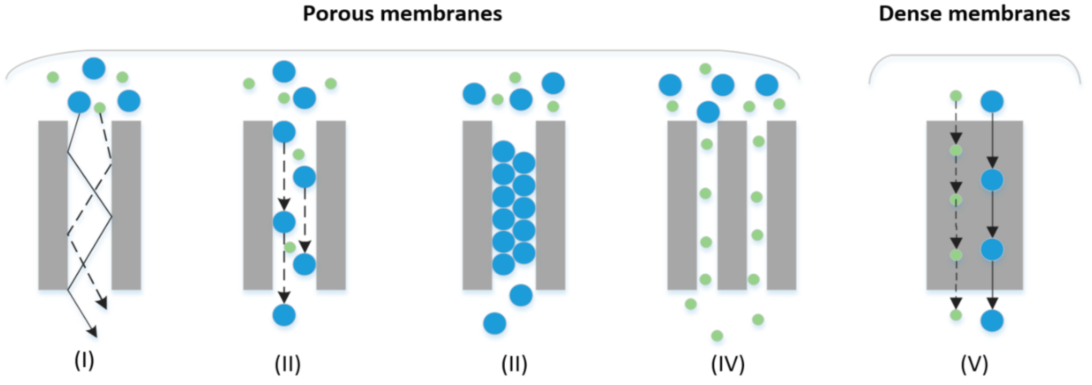
Figure 4.
Schematic of the working principle of an ideal electrochemical hydrogen separator.
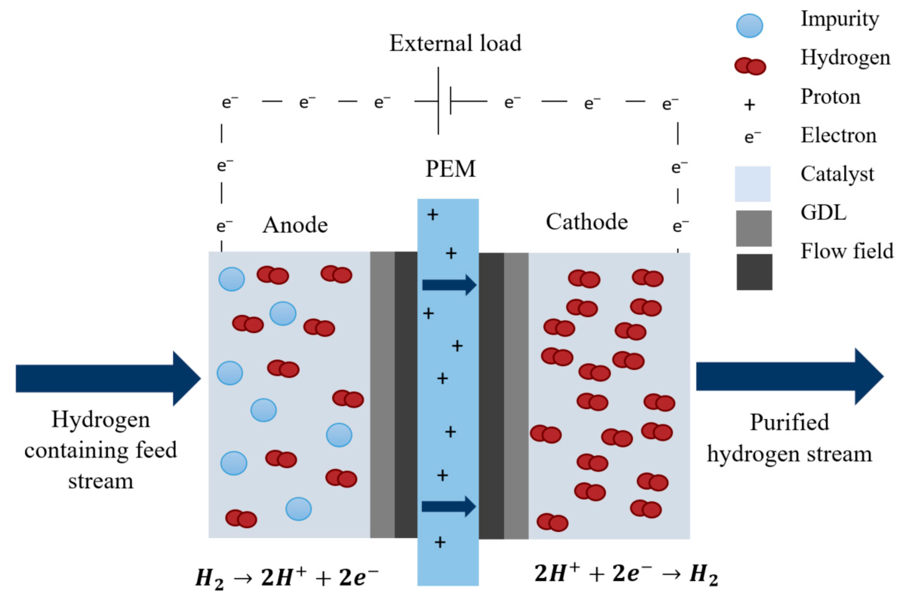
Figure 5.
H2/NH3 selectivity for: (a) 1500 ppm and (b) 3000 ppm NH3 (balance hydrogen) [188].
Figure 5.
H2/NH3 selectivity for: (a) 1500 ppm and (b) 3000 ppm NH3 (balance hydrogen) [188].


Table 1.
Summary of hydrogen production processes, their advantages and disadvantages, and technological status.
Table 1.
Summary of hydrogen production processes, their advantages and disadvantages, and technological status.
| Method | Advantages | Disadvantages | TML * | PE ** (%) | Cleanness *** | Impurities | References |
|---|---|---|---|---|---|---|---|
| Reforming: | |||||||
| SMR a | Most developed industrial process, lowest cost, existing infrastructure, high efficiency, best H2/CO ratio | Highest air emissions, system is complex, system is sensitive to natural gas quantities. Capital, operation, and maintenance cost. Fossil fuel feedstock. | 10 | 65–75 | NC/CCS | CO2, CO, CH4, N2 | [2,3,46,55,59,60,61,65,68,75,76,77,78,79] |
| POX c | Well-established. Variety of fuels, reduced desulphurization requirement, no catalyst required | Complex handling process, high operating temperature, low H2/CO ratio. Fossil fuel feedstock | 7–9 | 50 | NC | CO, CO2, H2O, CH4, H2S, COS and sometimes CH4 | [46,60,61,65,66,78,80] |
| ATR b | Lower temperatures than POX c, Requires less oxygen than POX c | Limited commercial application, required air or oxygen. Fossil fuel feedstock. | 6–8 | 60–75 | NC | CO, CO2, N2, CH4 and sometimes Ar | [60,81] |
| Gasification: | |||||||
| Coal | Abundant and affordable, Low-cost synthetic fuel in addition to H2 | Reactor costs, system efficiency, feedstock impurities, significant carbon footprint unless CCS is used. Separation and purification of gas products are difficult [82]. Fossil fuel feedstock (coal gasification). Season limitations and heterogeneity (biomass) | 10 | 74–85 | NC/CCS | N2, CO2, CO, CH4, H2S | [79,83,84,85] |
| Biomass | 3 (R&D) | 35–50 | NC/CCS | COx, SOx and CH4 | [2,78,84,86,87] | ||
| Electrolysis: | |||||||
| Water electrolysis | Simplicity of process design, compactness, renewable feedstock, cost effective way to produce hydrogen locally. Does not involve moving parts. Silent operation. | Energy input is required and it is more costly than fossil-fuel alternatives. | 9–10 | 62–82 | C | H2O | [2,66,67] |
* Technology maturity level (TML) is defined by a rating scale (1–10) used to indicate the commercial readiness of the technology. Level 1 refers to initial research stages, whilst level 10 refers to well-established mature commercial technologies [2]. ** Process efficiency (PE). *** C = clean without emissions, NC = not clean with emissions, CCS = quasi-clean using carbon capture and storage (CCS). Abbreviations: a Steam methane reforming (SMR). b Auto-thermal reforming (ATR). c Partial oxidation (POX).
Table 2.
Hydrogen fuel quality specifications.
| Constituent | Limits (μmol·mol−1 Unless Stated Otherwise) | Minimum Analytical Detection Limit |
|---|---|---|
| Hydrogen fuel index | >99.97% | |
| Water a | 5 | 0.12 |
| Total hydrocarbons b (C1 basis) | 2 | 0.1 |
| Oxygen | 5 | 1 |
| Helium | 300 | 100 |
| Nitrogen, Argon | 100 | 5 |
| Carbon dioxide | 2 | 0.1 |
| Carbon monoxide | 0.2 | 0.01 |
| Total sulphur c | 0.004 | 0.00002 |
| Formaldehyde | 0.01 | 0.01 |
| Formic acid | 0.2 | 0.02 |
| Ammonia | 0.1 | 0.02 |
| Total halogenates d | 0.05 | 0.01 |
| Particulate concentration | 1 mg·kg−1 | 0.005 mg·kg−1 |
a Due to the water threshold level, the following should be tested for, if there are concerns regarding the water content: (1) Sodium (Na+) < 0.05 μmol·mol−1 H2 or < 0.05 μg·L−1; (2) Potassium (K+) < 0.05 μmol·mol−1 H2 or < 0.08 μg·L−1 (3) Pottasium hydroxide (KOH) < 0.05 μmol·mol−1 H2 or < 0.12 μg·L−1; b e.g., ethylene, propylene, acetylene, benzene, phenol (paraffins, olefins, aromatic compounds, alcohols, aldehydes). The summation of methane, nitrogen and argon is not to exceed 100 ppm. c e.g., hydrogen sulphide (H2S), carbonyl sulphide (COS), carbon disulphide (CS2) and mercaptans. d e.g., hydrogen bromide (HBr), hydrogen chloride (HCl), Chlorine (Cl2) and organic halide (R-X).
| Properties | PSA | Membranes | Cryogenic |
|---|---|---|---|
| Min. feed purity (vol.%) | >40 | >25 | 15–80 |
| Product purity (vol.%) | 98–99.999 | >98 | 95–99.8 |
| Hydrogen recovery (%) | Up to 90 | Up to 99 | Up to 98 |
Table 4.
Summary of published articles on electrochemical hydrogen separation.
| Year | Type | Membrane | Catalyst * | Impurities | Temp. (°C) | Refs. |
|---|---|---|---|---|---|---|
| 2004 | Experimental | Nafion | Pt (B) | N2, CO2 | 30–70 | [166] |
| 2005 | Review | N/A | N/A | N/A | N/A | [167] |
| 2007 | Experimental | Nafion | Pt (A), Ru (C) | CO, CO2 | 20 | [156] |
| Experimental/modelling | Nafion | Pt/Pt-Ru (B) | Ar, CH4 | 20–70 | [168] | |
| Simulation | N/S ** | N/S ** | N2 | 25, 60 | [169] | |
| 2008 | Experimental | Nafion | Pt (B) | N2 | 25, 60 | [170] |
| Experimental | PBI | Pt (B) | CO, CO2, N2 | 120–160 | [49] | |
| 2009 | Experimental/modelling | Nafion | Pt (B) | Ar/C2H4 | 25 | [171] |
| Experimental | N/S ** | N/S ** | N2/CO2 | 60 | [172] | |
| 2010 | Experimental | PBI | N/S ** | N2; CO2, CO, CH4; N2,CO2, CO | 160–180 | [93] |
| 2011 | Experimental | Nafion | Pt/C (B) | CO2, H2O | 50–70 | [173] |
| Experimental | Nafion | Pt (B) | N2 | 35, 55, 75 | [161] | |
| Experimental | Nafion | Pt (B) | Ar | 20–70 | [159] | |
| 2012 | Experimental | Nafion | Pt/C, Pd/C (B) | CO2 reformate | 30–50 | [160] |
| 2013 | Experimental | PBI | Pt(B) | CO2 | 80, 160 | [174] |
| 2014 | Experimental | PBI | Pt (B) | Simulated reformate: N2, CO | 140–160 | [175] |
| Experimental | Nafion | Ir/C (B) | Ar, CO2 | 25, 70 | [176] | |
| 2016 | Experimental | Nafion | N/S ** | CO2, CO, CH4 | 25–75 | [177] |
| Experimental | SPPESK, Nafion | Pt (B) | CO2 | 20–60 | [178] | |
| 2018 | Experimental | Nafion | Pt-Ru (A), Pt (C) | CO2 | 25, 50 | [179] |
| 2019 | Experimental/modelling | Nafion | N/S ** | N2, CH4, He, CO2 | 28 | [180] |
| Experimental | Nafion | N/S ** | N2, CO2 and air | 15–22.5 | [181] | |
| Experimental case study: MEMPHYS (Membrane based purification of hydrogen system) system | N/S ** | N/S ** | N2 | 35 | [97] | |
| 2020 | Experimental | PBI | Pt (B) | N2, CO | 160–200 | [182] |
| Experimental/modelling | Nafion | Pt/C (B), Pt-Ru/C (A) and Pt/C (C), Pt-Ni/C (A) and Pt/C (C) | CO/Ar; N2 | 35 | [183] | |
| Experimental/modelling | Nafion | Pt/C (A), Pt-Ru/C (A) and Pt-Ru(C) | CO; CO2, CH4, CO, H2S | 35 | [184] | |
| Case study/modelling | N/A | N/A | H2,N2 and CO2 | N/A | [185] | |
| Review | N/A | N/A | N/A | N/A | [186] | |
| Review | N/A | N/A | N/A | N/A | [187] | |
| 2021 | Experimental | TPS | Pt-Co/C (A) and Pt/C (C) | CH4, CO2, and NH3 | 120–160 | [188] |
* A = anode; C = cathode, B = both electrodes; ** N/S = Not specified.
Table 5.
Hydrogen purity of the product gas (inlet stream properties: 56.7 mA·cm−2, 40 °C, 1 atm, 75 vol.% CO2) [178].
Table 5.
Hydrogen purity of the product gas (inlet stream properties: 56.7 mA·cm−2, 40 °C, 1 atm, 75 vol.% CO2) [178].
| Gas | Composition [%] | |||
|---|---|---|---|---|
| SPPESK-0.71 | Nafion 115 | Nafion 212 | Nafion/PTFE | |
| H2 | >99.99 | >99.99 | 99.79 | 99.25 |
| CO2 | <0.01 | <0.01 | 0.21 | 0.75 |
Publisher’s Note: MDPI stays neutral with regard to jurisdictional claims in published maps and institutional affiliations. |
© 2021 by the authors. Licensee MDPI, Basel, Switzerland. This article is an open access article distributed under the terms and conditions of the Creative Commons Attribution (CC BY) license (http://creativecommons.org/licenses/by/4.0/).
Share and Cite
MDPI and ACS Style
Vermaak, L.; Neomagus, H.W.J.P.; Bessarabov, D.G. Recent Advances in Membrane-Based Electrochemical Hydrogen Separation: A Review. Membranes 2021, 11, 127. https://doi.org/10.3390/membranes11020127
AMA Style
Vermaak L, Neomagus HWJP, Bessarabov DG. Recent Advances in Membrane-Based Electrochemical Hydrogen Separation: A Review. Membranes. 2021; 11(2):127. https://doi.org/10.3390/membranes11020127
Chicago/Turabian StyleVermaak, Leandri, Hein W. J. P. Neomagus, and Dmitri G. Bessarabov. 2021. "Recent Advances in Membrane-Based Electrochemical Hydrogen Separation: A Review" Membranes 11, no. 2: 127. https://doi.org/10.3390/membranes11020127
Note that from the first issue of 2016, this journal uses article numbers instead of page numbers. See further details here.