Review

Membrane-Based Technologies for Post-Combustion CO2 Capture from Flue Gases: Recent Progress in Commonly Employed Membrane Materials

by
Petros Gkotsis
,
Efrosini Peleka
and
Anastasios Zouboulis
*
Laboratory of Chemical and Environmental Technology, Department of Chemistry, Faculty of Sciences, Aristotle University, GR-54124 Thessaloniki, Greece
*
Author to whom correspondence should be addressed.
Membranes 2023, 13(12), 898; https://doi.org/10.3390/membranes13120898
Submission received: 31 October 2023 / Revised: 22 November 2023 / Accepted: 30 November 2023 / Published: 2 December 2023

Abstract

:
Carbon dioxide (CO2), which results from fossil fuel combustion and industrial processes, accounts for a substantial part of the total anthropogenic greenhouse gases (GHGs). As a result, several carbon capture, utilization and storage (CCUS) technologies have been developed during the last decade. Chemical absorption, adsorption, cryogenic separation and membrane separation are the most widely used post-combustion CO2 capture technologies. This study reviews post-combustion CO2 capture technologies and the latest progress in membrane processes for CO2 separation. More specifically, the objective of the present work is to present the state of the art of membrane-based technologies for CO2 capture from flue gases and focuses mainly on recent advancements in commonly employed membrane materials. These materials are utilized for the fabrication and application of novel composite membranes or mixed-matrix membranes (MMMs), which present improved intrinsic and surface characteristics and, thus, can achieve high selectivity and permeability. Recent progress is described regarding the utilization of metal–organic frameworks (MOFs), carbon molecular sieves (CMSs), nanocomposite membranes, ionic liquid (IL)-based membranes and facilitated transport membranes (FTMs), which comprise MMMs. The most significant challenges and future prospects of implementing membrane technologies for CO2 capture are also presented.

1. Introduction

Global warming, which is caused by the increase in greenhouse gases (GHGs) in the atmosphere, has become a considerable concern as it poses a major threat to human health, energy security and ecosystems [1]. Carbon dioxide (CO2) emissions, which result from the combustion of fossil fuels and from industrial processes, account for approximately 65% of the total anthropogenic GHGs globally [2]. Almost 40% of these emissions result from the electricity production of coal-fired power plants [3]. As a result, carbon (CO2) capture, utilization and storage (CCUS) technologies are urgently required to minimize CO2 emissions and maintain climate temperature [4,5].
Carbon capture processes are categorized into four main groups: (i) post-combustion capture, (ii) pre-combustion capture, (iii) oxy-fuel combustion capture and (iv) capture from industrial process streams. The selection of the applied process depends on the gas stream composition and the emission site; in some cases, CO2 capture is required at the beginning of the process operation, while others may require CO2 capture at the end of the process operation (exhaust phase) [6]. Post-combustion capture is the separation of CO2 from flue gases, which are produced after the combustion of fossil fuels or biomass and generally contain 73–77% N2, 15–16% CO2, H2O (5–7%), O2 (3–4%) and other impurities, such as SOx and NOx [3]. Post-combustion capture process is regarded as a technically and economically viable solution for reducing carbon emissions in a variety of sectors/emitters, where decarbonization is possible, but costly in the near future. These emitters include fundamental industrial sectors, which rely on the combustion of fossil fuels, such as power generation plants and steel or cement production industries, but also secondary emitters, such as chemical plants and waste incinerators. Compared to the other three carbon capture processes, post-combustion capture can be easily retrofitted to existing plants and, therefore, it may be the only effective and economic way to reduce CO2 emissions without affecting the process upstream, leading to the transition towards net-zero industries [7,8].
The most common post-combustion CO2 capture technologies include chemical absorption (with liquid solvents), adsorption (with solid adsorbents), cryogenic separation and membrane separation. Among them, chemical absorption is the most mature technology as it can achieve high CO2 capture capacity and removal efficiency, reaching 100% when monoethanolamine (MEA) is employed as a solvent. However, chemical absorption with amines presents several challenges, such as high requirements for energy regeneration, a low reaction rate and a strong environmental impact due to the presence of corrosive or volatile solvents. As a result, alternative carbon capture technologies are increasingly examined both on a research level (lab-scale applications) and in real field conditions (pilot- or full-scale plants) [9].
Unlike CO2 capture technologies with solvents or adsorbents, CO2 capture with membranes presents significant benefits, such as small footprint, easy scale-up, low capital and operating cost and low energy consumption, as they can deliver high-pressure CO2 without utilizing chemical solutions or energy-intensive steam. Membrane separation technology, which was first developed in the 1980s, employs CO2-selective membranes to separate CO2 from a gas stream [10,11]. This technology has been applied successfully in other applications as well, such as biogas upgrading and natural gas purification. Despite its advantages, however, the major drawback of membrane separation still remains to be the trade-off between selectivity and permeability, which are the most important factors affecting process efficiency and economics [12,13]. Therefore, the development of novel membrane technologies which capture CO2 more efficiently and selectively is required. Over the last few years, several studies reviewed and compared membrane-based technologies for CO2 capture from flue gases or other gas streams. Da Conceicao et al. (2023) [14] summarized the literature that is linked to the development or application of membrane separation in terms of separation modeling and process simulations. Singh et al. (2022) [15] featured current advancements in CO2 capture with membranes, but focused mainly on the utilization of polymeric membrane materials. In their review on membrane technologies for post-combustion carbon capture, Favre et al. (2022) [16] provided a compact, but rather limited, overview regarding commonly employed membrane materials, as they did not include the latest advancements in composite membranes, which are increasingly fabricated and applied in recent years. The present study aims to review the main post-combustion CO2 capture technologies from flue gases, but from the standpoint of the progress which has recently been made after the application of membrane-based technologies. Specifically, the objective of the present review is to present the state of the art in novel membrane materials for carbon capture, and primarily focuses on the utilization of mixed-matrix membranes (MMMs) with enhanced intrinsic and surface properties that promote CO2 capture.

2. Main Processes for CO2 Capture

CO2 capture from various gas streams can be classified as follows (Figure 1): (i) post-combustion capture, (ii) pre-combustion capture, (iii) oxy-fuel combustion capture and (iv) capture from industrial process streams. Selecting the appropriate capture process depends on the CO2 content in the gas stream, the gas stream pressure and the type of fuel used (whether it is solid or gas); thus, not all capture processes are compatible with all systems. All processes, however, involve separating CO2, O2 or H2 from a gas stream, such as a flue gas, air, a natural gas or a biogas, and can be achieved using physical or chemical solvents, solid sorbents, membranes, cryogenic separation or via a combination of these methods [17,18,19,20,21].
Every CO2 capture process has advantages and disadvantages. Post-combustion capture allows the easy retrofit of existing plants and, thus, an immediate reduction in emissions. The disadvantages include inefficient capture due to the low partial pressure of CO2 and the presence of impurities that degrade the employed solvents. Pre-combustion capture benefits from the high partial pressure of CO2 and concentrated gas streams, which results in efficient absorption and reduced solvent consumption. Nevertheless, the main drawback lies in the demand for gasification, which increases process cost and complexity. In oxy-fuel capture, a fuel is burnt with oxygen of high purity, and a concentrated CO2 stream that promotes absorption is generated. However, the air separation process, which is required for oxy-fuel combustion, is very energy-intensive [22,23,24].

2.1. Post-Combustion Capture

Post-combustion capture refers to the separation of CO2 from flue gases, which are produced after the combustion of fossil fuels or biomass, and usually present a low CO2 content (3–20%), a low partial pressure of CO2 (0.03–0.2 bar) and high temperatures (120–180 °C), but contain NOx and SOx impurities. During this process, the flue gas is not directly discharged into the atmosphere. It is transferred to a specially designed equipment that separates the biggest amount of the produced CO2. The separated CO2 is led to a storage tank, and the flue gas which has remained is vented to the atmosphere. Aside from flue gases, carbon capture from various industries, e.g., cement and stainless-steel manufacturing facilities, can also be classified as post-combustion capture, although these industries yield higher CO2 concentrations compared to the typical flue gases encountered in most post-combustion power plants. Nowadays, chemical absorption, which employs the utilization of aqueous amine solutions, is the most commonly applied post-combustion capture process [19,25].

2.2. Pre-Combustion Capture

Pre-combustion capture refers to CO2 capture from a synthesis gas (syngas) after the conversion of CO into CO2. This process initially involves the reaction of a fuel with O2 (or air) and/or steam to produce mainly a synthesis gas or a fuel gas, which is composed of CO and H2. CO then reacts with steam in a catalytic reactor, which is known as a ‘shift converter’, to form CO2 and more hydrogen in a process called water–gas shift reaction (WGS). After the WGS reaction, the CO2 content in the flue gas is high, i.e., in the range of 15–60% (dry basis), at a total pressure of 2–7 MPa, and physical solvents (e.g., Rectisol or Selexol) are usually employed for CO2 capture. The resulting fuel, which is rich in hydrogen, can be used for heat and power generation, e.g., in furnaces, boilers, engines, gas turbines and fuel cells. A 15–40% CO2 content at increased pressures (200–600 psi) is usually contained in most pre-combustion gas streams [19,20,25,26].

2.3. Oxy-Fuel Combustion Capture

Oxy-fuel combustion capture was initially developed to yield CO2 of high purity (>99%) during enhanced oil recovery (EOR). In this relatively new process, almost pure oxygen (95–99%), instead of air, is used for combustion, resulting in a flue gas that contains H2O and CO2 at a very high concentration. When pure oxygen is used to burn the fuel, the temperature of the flame is very high, but CO2 and the rich-in-water flue gas can be recycled in the combustor to change this. For the production of oxygen, cryogenic air separation is usually applied or, to a lesser extent, other alternative technologies (e.g., membrane separation) [19,25,26].

2.4. Capture from Industrial Process Streams

Several industrial applications involve process streams, which present the opportunity for capturing large quantities of CO2 at relatively low costs. CO2 capture from these sources has been applied for more than 80 years, although most of the captured CO2 is usually discharged into the atmosphere since there is no incentive for further utilization or storage. Capturing CO2 from industrial process streams may not be the complete answer to current climate change requirements since the amount of CO2, which is generated during combustion, is much higher; however, it can provide the ‘starting point’ for the initial CO2 capture. Current examples of CO2 capture from industrial process streams include the purification of natural gas and the production of syngas for the synthesis of ammonia, alcohols and synthetic liquid fuels. Other examples, which involve sources of CO2 that are usually not captured, include fermentation and cement and steel production facilities. Finally, there are industrial process streams which employ two or more of the aforementioned CO2 capture processes, regardless of whether they contain a low or high CO2 concentration [19,21].

3. Post-Combustion CO2 Capture Technologies

In comparison with the other CO2 capture processes (i.e., pre-combustion capture, oxy-fuel combustion capture and capture from industrial process streams), post-combustion capture is technologically more mature and presents the highest short-term potential for CO2 reduction, as it can be easily incorporated and adjusted to existing fossil-fueled power plants or implemented into other industrial CO2 emitters (e.g., cement industries, iron and steel production industries). This retrofit of existing power plants is related to the smaller interferences of the capture process with other components. However, the process should be appropriately adapted to treat impurities (mainly SOx and NOx) and the considerable amounts of oxygen, which are contained in flue gases [26,27,28].
The main post-combustion CO2 capture technologies include chemical absorption (with liquid solvents), adsorption (with solid adsorbents), cryogenic separation and membrane separation [29,30]. Table 1 presents the main benefits and challenges of these technologies. Selecting the appropriate capture technology depends on the specific discharge conditions, and the main criterion is the flue gas state, i.e., its composition, flow rate, temperature and CO2 content. This selection is also affected by the desired production (e.g., CO2 purity and transport pressure) and the discharged standards (e.g., H2S, NOx and SOx) [31]. The CO2 capture technologies which have been adequately developed and applied commercially (TRL9) include chemical absorption and cryogenic separation. Chemical absorption allows CO2 capturing from streams with a low CO2 content and achieves high CO2 capture efficiencies. Cryogenic separation is suggested for increased CO2 concentrations (>90%) and produces high-purity liquified CO2. However, these technologies are highly energy-demanding. On the contrary, membrane technologies, which employ the pressure difference as a driving force to achieve CO2 separation, may become a more efficient option, especially when the treatment of CO2 stream (with a concentration of >10%) is coupled with the appropriate tuning of the driving force. In addition, separation with membranes does not require storing or treating of hazardous chemicals, although it may present a lower separation efficiency than chemical absorption and cryogenic separation. Currently, post-combustion CO2 capture from flue gases with membrane separation is on a pilot-scale level (TRL-6) [32].
It should be noted that chemical absorption and membrane separation cannot be directly compared in terms of energy consumption due to the different energy sources (i.e., heat for absorption and electricity for membrane). Similarly, an overall cost comparison of CO2 capture technologies would also be difficult, and each technology should be examined case by case, taking into account the specific conditions that are applied, such as flue gas composition, flue gas flow rate and targeted CO2 capture capacity. Nonetheless, comparative (techno-)economic assessments have been conducted for the main CO2 capture technologies. According to Hongjun et al. [33], who compared, in 2011, the cost of chemical absorption, membrane separation and Pressure Swing Adsorption (PSA) for CO2 capture from flue gases of coal-fired power plants, the cost ranged between USD 30 and USD 60 per ton for chemical absorption, between USD 50 and USD 78 per ton for membrane separation and between USD 40 and USD 63 per ton for PSA. In 2017, after reviewing chemical absorption and membrane separation for their energetic and economic performances, Wang et al. [30] concluded that (i) chemical absorption still remains energy-intensive and costly, despite the diversity of optimization methods that are applied to reduce the energy consumption and cost of this technology; (ii) although membrane separation was initially expected to compete with chemical absorption, it presents advantages only at a low CO2 capture percentage (<90%), and its capture ability is limited by the characteristics of the employed membrane materials; and (iii) it is difficult to compare the energetic and economic results in the literature and infer general conclusions since the relevant research studies are usually based on specific conditions and assessments. Four years later (2021), Zanco et al. [8] compared chemical absorption, adsorption (with zeolite) and membrane separation for post-combustion CO2 capture from flue gases. The comparative assessment showed that adsorption and membrane separation can become cost-competitive on a small scale (i.e., <100 tons of processed flue gas per day) with low recovery rates (i.e., <40%); however, chemical absorption remains the most cost-effective option for the majority of facilities and recovery rates. In 2022, the cost for carbon capture projects was estimated globally at USD 60–110/per ton, and it is expected to decrease further to USD 30–50 per ton by 2030 [34].

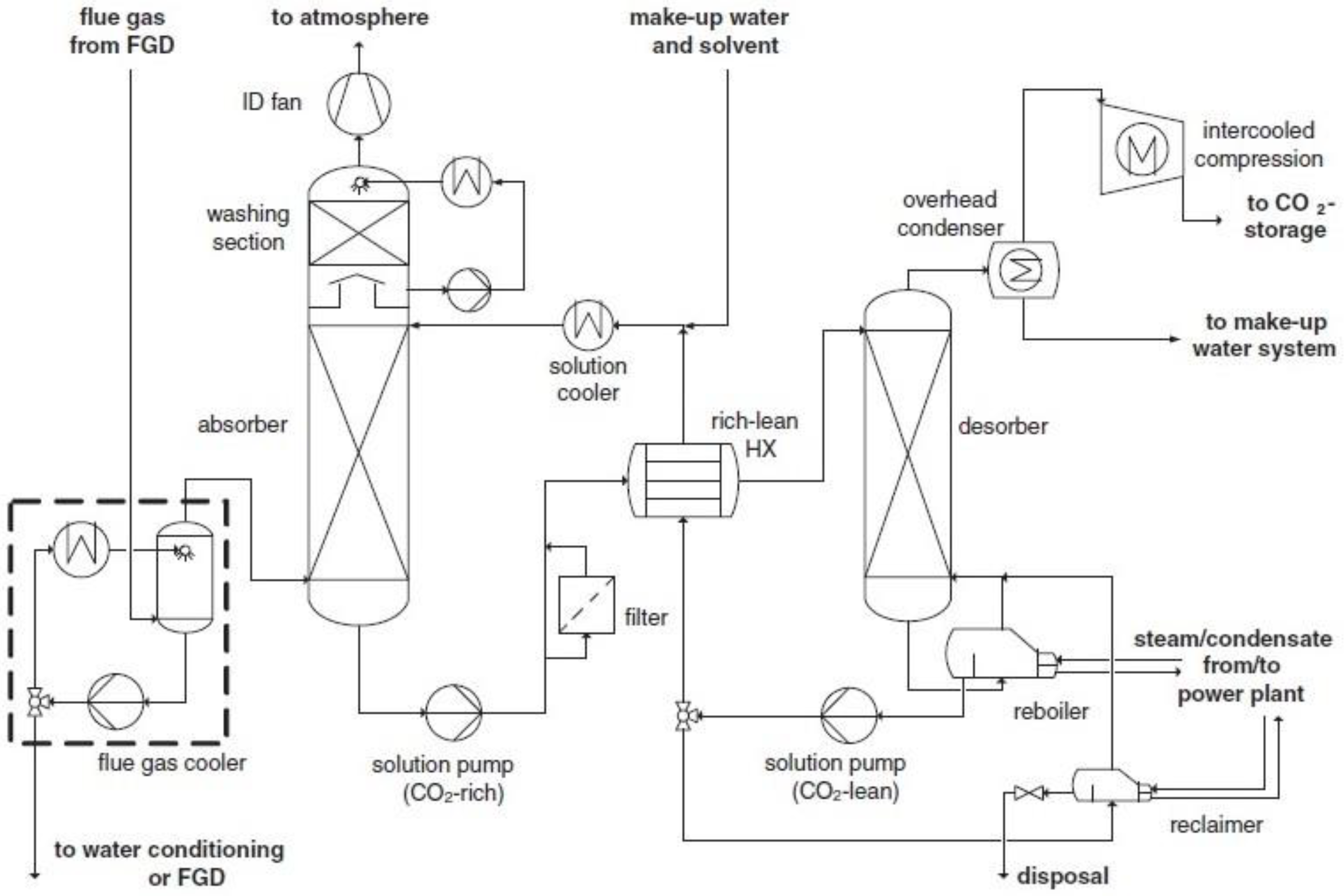
3.1. Chemical Absorption

Absorption is the most applied technology for CO2 capture because it is technologically mature, commercially available and easily adaptable to several processes, such as post-combustion, pre-combustion and oxy-fuel combustion capture. In this technology, CO2 is selectively absorbed from a flue gas by means of a lean solvent via a physical or chemical mechanism. Physical absorption is based on the solubility of carbon dioxide in the solvent, and chemical absorption is based on the chemical reaction between carbon dioxide and the solvent. The latter is usually preferable for CO2 capture from power plants as it presents higher CO2 selectivity at low CO2 partial pressures [35,36].
In chemical absorption technology (Figure 2), first, CO2 is chemically absorbed into a lean solvent in an absorption column (absorber), and then it is desorbed by utilizing a stripping gas of high temperature in a column where the solvent is regenerated (desorber or stripper), consuming a significant amount of energy. More specifically, the cooled flue gas initially enters the absorber and contacts, in a counter-current flow, the descending solvent, which is usually a 15–40 wt % MEA aqueous solution. The solvent becomes ‘rich’, i.e., absorbs CO2, at 40–60 °C and 1 bar, and exits the absorber, while the clean flue gas exists from the top of the column before it is passed to a wash column and vented to the atmosphere. The rich solvent is then heated in a cross-flow heat exchanger (through the regenerated later-coming hot lean solvent from the desorber) and pumped to the top of the desorber where it is regenerated at increased temperatures (100–120 °C) and at a pressure of 1.5–2 atm. Heat is provided by a reboiler, which is the most important energy penalty of the process. The regenerated solvent is finally pumped back to the absorber via the cross-flow heat exchanger, which decreases the temperature [35,37].
Various solvents are used in the absorption technology, namely amines, ionic liquids, ammonia, deep eutectic solvents and water-lean solvents. Monoethanolamine (MEA) is one of the most employed (and studied) solvents on the lab, pilot and full scales. MEA presents low cost, viscosity and volatility, which are considered desirable properties for CO2 capture. In addition, a significant amount of data/information is available regarding its physical and chemical properties (degradation, solubility of O2, etc.), both in lab-scale reactors and in pilot-scale or industrial capture plants. The most important drawback, however, is the high energy amounts that are needed to break the bonds of the formed carbamate (CO2 + MEA) and regenerate the solvent. This is almost 57.5% of the total energy consumption, accounting for 50% of the operating cost [38,39,40]. Furthermore, the incorporation of such systems in a power plant increases almost 70–80% of the electricity cost and reduces 25–30% of the net efficiency of the power plant [39,41]. MEA is also highly oxidative and easily degrades when it comes in contact with impurities, such as excess oxygen and sulphur dioxide. This degradation accounts for almost 10% increase in the operating cost. Consequently, the relevant research studies aim to either decrease the high consumption of energy via the application of alternative solvents and process configurations, or to employ less energy-intensive CO2 capture technologies where solvent regeneration is not required (e.g., membrane separation) [35,42].

3.2. Adsorption

In this technology, an adsorbent agent is used to selectively adsorb and separate CO2 from the flue gas in a two-step process (Figure 3); CO2 is initially adsorbed on the surface of the adsorbent agent, which is then regenerated usually via the application of heat (Temperature Swing Adsorption, TSA) or by reducing the pressure (Pressure Swing Adsorption, PSA) [43,44]. For TSA, the energy consumption derives from heating, while for PSA, the energy consumption mainly comes from the compressor system [45]. It is reported that TSA processes offer additional advantages compared to PSA. First of all, the flue gas, which is emitted at an almost ambient pressure, does not require pressurization. Secondly, waste heat can be used to provide the energy that is needed for temperature swing. Therefore, the low temperature difference between the regeneration and adsorption steps of TSA (30–150 °C) and the possibility to use the available waste heat reduce the operating cost, thereby promoting the implementation of TSA [46]. Nowadays, TSA is mainly employed for post-combustion capture of CO2 from flue gases [47].
Adsorption can be characterized as physical or chemical, depending on the involved mechanism. During physical adsorption (or physisorption), CO2 molecules attach to the pore walls of the adsorbent agent primarily through microscopic forces (Coulomb force and Van der Waals force), without forming chemical bonds. At ambient temperature, CO2 physisorption takes place and the gas uptake is directly related to the porous structure of the adsorbent’s surface. Chemical adsorption (or chemisorption) refers to the formation of chemical bonds between CO2 and the adsorbent surface. During chemisorption, coating or chemical grafting occurs on the surface of a porous material by integrating basic groups that interact with the acidic CO2 molecules. The adsorption of CO2 at increased temperatures (>140 °C) is primarily governed by chemisorption. In the temperature range of 25–140 °C, both physisorption and chemisorption can occur [44,49].
The selection of the adsorbent agent is one the most important factors to achieve effective separation when the adsorption technology is considered for CO2 capture. The adsorbent agent should have high CO2/N2 selectivity, high adsorption capacity, fast kinetics, high surface area, mild desorption ability, high resistance/tolerance towards moisture and impurities, high mechanical strength, low operating cost and high stability when applied in a multi-cycle operation [50]. Typical adsorbents for CO2 capture are zeolites, activated carbon, alumina, silicates and metal–organic frameworks (MOFs) [51,52].
The application of adsorption can result in high energy savings compared to the commonly applied absorption with amines. In addition, it is a simple, environmentally friendly technology that is quite readily retrofitted to existing plants and, thus, offers the flexibility to capture CO2 from different industrial CO2 sources due to the different available adsorbent regeneration modes and reactor types [51,53]. Other advantages include high adsorption capacity at ambient conditions, stability for long-term application, low cost for regeneration and fast kinetics [50]. However, although adsorption is a relatively mature technology for some industrial applications of large scale, its application in real-field post-combustion CO2 capture process still presents significant challenges concerning the adsorption materials, the gas–solid contact systems and the regeneration mode. In addition, the flue gas used should be rich in CO2 because the majority of the available adsorbents have low selectivity. For this reason, current research studies have focused mainly on the development of innovative adsorbent materials and aimed to reduce energy consumption by minimizing the adsorption heat and maximizing the adsorbents’ capacity [37,53].

3.3. Cryogenic Separation

Cryogenic separation (Figure 4) exploits the condensation (cryogenic distillation techniques) or desublimation points (cryogenic desublimation techniques) of the gases that are contained in a flue gas. In the first group of techniques, distillation columns are employed to separate and recover CO2 in liquid form. The obtained CO2 is of high purity; however, these techniques are highly energy-intensive because very high pressures are required to prevent the formation of CO2 frost. During desublimation techniques, CO2, which is at atmospheric pressure and a temperature of −78.5 °C, desublimates directly from the gaseous state to the solid state [54].
When compared to the other CO2 capture technologies, the principal advantage of cryogenic separation is the high recovery rate and purity. In addition, it is a relatively simple technology that employs a two- or three-step sequence (compression, expansion and separation); it does not demand the utilization of volatile chemicals (e.g., as in absorption); and it is conducted under mild pressures [29,55]. However, cryogenic separation demands high power to operate the refrigeration unit, which increases the operating cost, and it also requires feed gas pre-treatment and dehydration to avoid CO2 freezing in the cold section of the fractionation equipment [56].
Figure 4. Process flow diagram of cryogenic separation technology for CO2 capture [57].
Membranes 13 00898 g004

3.4. Membrane Separation

During membrane separation, CO2-selective membranes are utilized to separate CO2 from a flue gas stream. CO2 capture with membrane separation was applied initially for the purification of natural gases, as an alternative to the utilization of amine solvents, in the 1980s. Since then, membrane separation technologies have expanded their market share due to a series of benefits, such as low capital cost, low energy consumption, low space requirements and high sustainability in distant areas [10,58]. In addition, they are environmentally friendly, have simple operation and do not produce harmful wastes, as opposed to, e.g., chemical absorption which employs amine absorbents [59]. The following section presents the basic principles, the main process configurations and membrane materials, and the current advancements regarding the application of membrane-based technologies, mainly for efficient CO2 capture from exhaust flue gases.

4. CO2 capture with Membrane Technologies

4.1. Basic Principles and Mechanism of Membrane Gas Separation

During gas separation using membrane technology, a membrane acts as a filter that allows specific molecules to permeate (e.g., CO2) but prevents other molecules from entering the membrane (e.g., CH4 and H2O) (Figure 5) due to characteristics such as gas–membrane chemical interactions or the kinetic diameter. Membrane processes, such as micro-filtration, ultra-filtration, nano-filtration and reverse osmosis, are widely used in solid–liquid separations [60]; however, membrane gas separation is also attracting intensive research for carbon capture, utilization and storage (CCUS) during recent years [10,61].
For membranes with no permanent porosity, i.e., membranes that consist of dense polymeric materials, the most widely adopted mechanism/model for mass transport is the solution-diffusion model. According to this model, transport occurs in three steps: (1) dissolution or sorption of a gas into the membrane at the high-pressure material side, (2) diffusion of the sorbed gas through the membrane, and (3) desorption of the gas from the membrane at the low-pressure material side. The chemical potential difference between the high-pressure and low-pressure contacting phases controls the driving force, which is created through gas compression or vacuum. For ideal gas contacting phases, the gas flux across the membrane is calculated using the following equation:
J i = Q i δ · ( P r · x i P p · y i )
where Ji is the flux across the membrane of species i (mol/m2/s); Qi is the membrane permeability for species i (mol·m/m2/s/Pa); δ is the effective membrane thickness (m); Pr and Pp are the feed/retentate high pressure and the permeate low pressure (Pa), respectively; and xi and yi are the high-pressure and low-pressure gas-phase mole fractions (mol/mol), respectively. The permeability is equal to the product of gas solubility and diffusivity in the membrane. The ratio of permeability to membrane thickness in Equation (1) is defined as the gas permeance: q Q i δ · (mol/m2/s/Pa). Commonly, permeance is expressed in gas permeation units (GPUs), where 1 GPU = 3.35 · 10−10 (mol/m2/s/Pa).
Selectivity expresses the ability of a membrane to separate two gases. For a pair of gases, i and j, selectivity is defined as the ratio of gas permeabilities or permeances:
a i , j = Q i Q j = q i q j
where component i is the gas with the higher permeability, resulting in a selectivity greater than 1. In membrane technologies, selectivity and permeability are the most important parameters for efficient gas separation and determine the process economics; the energy (operating) cost is controlled by selectivity, whereas the membrane area (capital) cost is controlled by permeability. An increase in selectivity decreases the amount of gas that must permeate from the high-pressure feed to the low-pressure permeate to achieve the desired targets for product purity; this decreases the compression energy lost due to permeation. An increase in permeability or permeance, i.e., of the gas permeation flux per unit of driving force, reduces the area of the membrane and the capital cost that is necessary to achieve a specific feed or product flow rate [14,62]. The Robeson correlation is an empirical correlation that presents a trade-off between permeability and selectivity of gases, and its upper boundary is usually employed to assess the performance of membrane systems (Figure 6). To address the challenges in reducing carbon capture cost, a membrane material should be on the Robeson upper bound (or above it), i.e., in the region of high permeability/moderate selectivity [63,64].

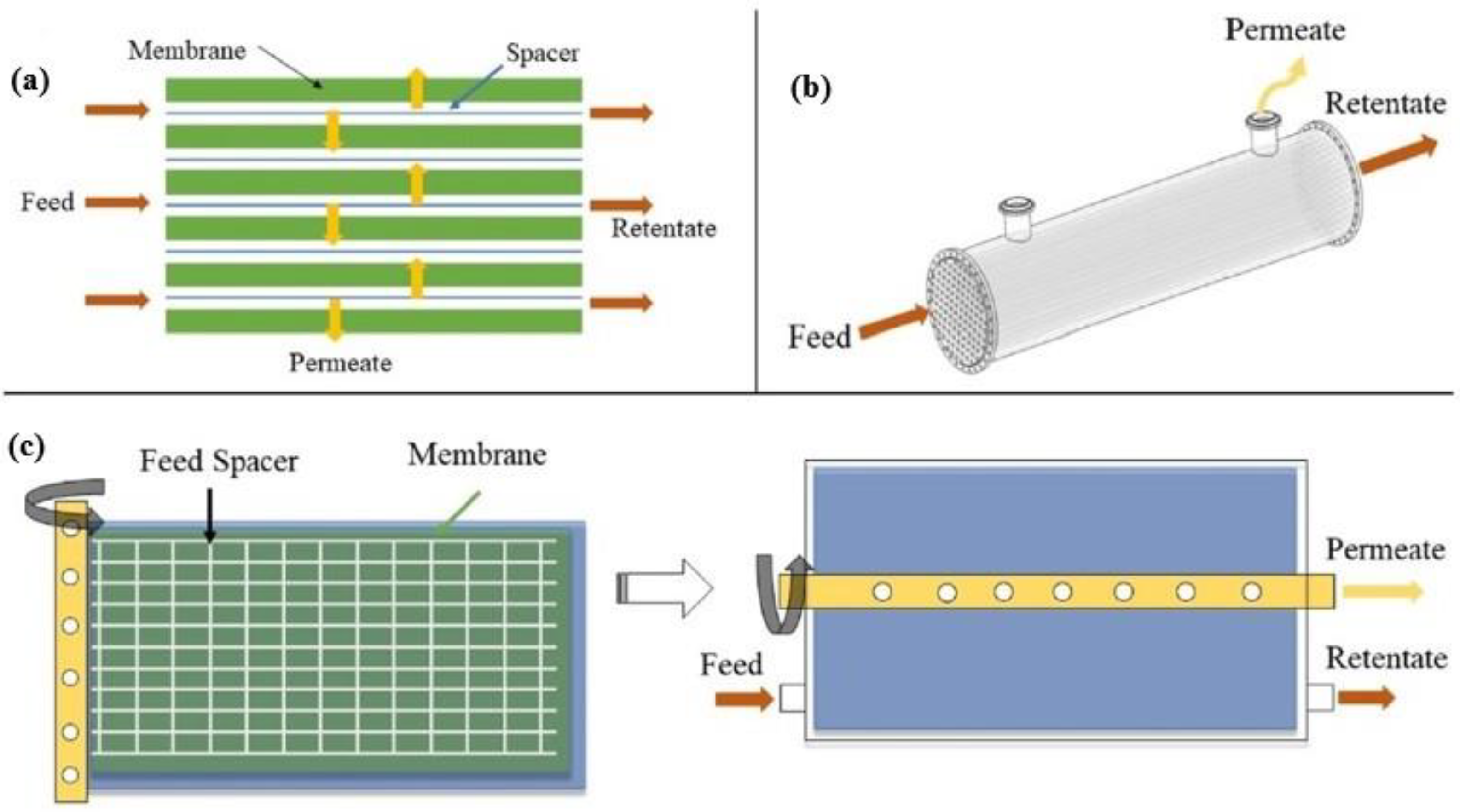
4.2. Membrane Configurations and Process Engineering

Typical membrane configurations for separating CO2 include hollow fiber (HF), flat-sheet (FS) and spiral-wound (SW) membranes (Figure 7). Hollow fiber membranes, which contain hundreds or thousands of hollow fibers packed into bundles, are the most studied membrane configuration due to their high surface area per unit volume, which promotes gas transfer. However, they present drawbacks, such as fiber fouling and significant pressure drops. On the contrary, flat-sheet membranes, which are usually stacked on top of each other, present lower pressure drops and enhanced mass transfer because they employ specially designed feed spacers. In addition, they can be easily fabricated and physically or chemically cleaned. Spiral-wound membranes actually consist of flat-sheet membranes that are rolled around a collection tube [65,66].
According to the employed process engineering configuration, gas separation using membranes can occur in a single-stage process with one membrane module or in a two- (or multi-)stage process with two (or more) membrane modules that are placed in series or in a parallel configuration (Figure 8) [67,68]. During the single-stage process (Figure 8a), high selectivity is needed to achieve 95% purity and 90% recovery of CO2. Consequently, it is difficult to achieve high targets using the single-stage membrane process, mainly because the purity of the final product is limited by the low CO2 content in the feed gas and by the trade-off effect between recovery and purity. On the contrary, high purity and recovery targets are achieved more easily in the two-stage membrane process (Figure 8b) as the gas recycling enhances the recovery of CO2 significantly. However, the two-stage membrane process consumes more power since more compressors (or vacuum pumps) are needed, and the gas recycling increases the required membrane area. Consequently, during membrane separation with two or more stages, the main target is to reduce energy consumption and membrane area [69].

4.3. Membrane Materials

Each membrane material presents advantages and disadvantages, which are concerned with the separation performance, material cost, lifetime and other characteristics, such as chemical and thermal stability, and mechanical strength. Organic (polymeric) membranes, inorganic membranes and mixed-matrix membranes (MMMs) are the main membranes applied for post-combustion CO2 capture [70,71,72].
Among various membrane materials, polymeric materials present inherent advantages in terms of cost, variety and ease of processing. Polymers, including polyacetylene [73], polyaniline [74], polyamides [75], polyimides [76], polyetherimides [77], polycarbonates [78], poly(phenylene oxides) [79], poly(ethylene oxides) [80], polysulfones [81] and cellulose acetate [82], have been examined for post-combustion CO2 capture. Generally, the solution-diffusion transport mechanism and the facilitated transport mechanism are broadly adopted as the principal mechanisms when the design of new polymers is considered. Membranes which are made from the aforementioned polymeric materials follow the solution-diffusion mechanism. In facilitated transport membranes, CO2 transport is enhanced by the interaction between CO2 molecules through reversible reactions (see Section 5.5). Compared to other materials, polymeric materials can be regarded as the optimal materials due to many characteristics, such as thermal stability, mechanical strength and chemical resistance. By controlling the polymer preparation and chemical composition process, the permeability and selectivity of these membranes can be easily adjusted. In addition, polymeric membranes are one of the best options due to the development of membrane technologies in various industries, such as biogas upgrading and petrochemicals. However, CO2 adsorption via polymer-based materials can cause swelling and plasticization problems [15,83]. Table 2 presents the CO2/N2 separation performance for various polymer-based membranes.
Non-polymeric materials, such as activated carbon, zeolites, silica and metal–organic frameworks (MOFs), are also emerging for CO2 capture. These membranes are more stable than polymeric membranes and, therefore, they are strong candidates for the efficient separation of gas mixtures, especially under harsh operating conditions. However, although inorganic membranes can be used in adverse conditions, the construction and sealing of the relevant modules for applications of high temperatures are quite difficult, and the cost of production is often much higher in comparison with polymer membranes. Ceramic membranes, which usually consist of aluminum oxide (Al2O3), titanium oxide (TiO2) or carbon nanotubes (CN), are a group of inorganic membranes with improved properties in terms of mechanical strength, thermal stability and chemical stability. Nonetheless, they present short operating time and low flexibility to form HF or SW membranes; as a result, their utilization in CO2 capture is still under research [72,83,92].
The limitations of membranes that are made from pure polymeric or inorganic materials prevent their widespread utilization in gas separation processes. Although pure polymeric membranes present exceptional mechanical properties, which allow their easy processing, they are limited by the trade-off effect that prevents achieving both high selectivity and permeability. Pure inorganic membranes present high selectivity or permeability, but they are thick and fragile and, thus, it is difficult to use them on a full-scale level. Aiming to overcome the aforementioned issues, the co-blending of organic and inorganic materials has been proposed to fabricate composite or mixed-matrix membranes (MMMs) with high permeability, selectivity, enhanced mechanical properties and potential for large-scale implementation. As a result, current research in membrane-based gas separation focuses mainly on the synthesis of composite membranes, which are usually fabricated via the integration of innovative inorganic materials, also known as ‘fillers’, into polymeric membranes [93,94]. The following section presents the latest developments regarding the use of these membranes for separating CO2.

5. State of the Art in CO2 Capture with the Use of Membrane Technologies

The application of membrane separation processes for CO2 capture is increasingly gaining traction during the last decade. Membrane technologies are environmentally friendly, energy-efficient and easily scalable, while also presenting cost-effectiveness and design simplicity [95]. As concerns carbon capture, membrane technologies are employed mainly for H2/CO2 separation during pre-combustion, CO2/N2 separation during post-combustion and O2/N2 separation during oxy-fuel combustion. This section focuses primarily on the latest developments of membrane separation processes for CO2/N2 separation during post-combustion capture.
The most recent advances in CO2 capture using membrane technologies principally involve employing a membrane material; the vast majority of research studies that examine membrane-based technologies for post-combustion CO2 capture focus on the fabrication and application of novel membrane materials which selectively separate CO2 from N2. In most of them, a polymeric material (continuous phase) is combined with an inorganic material of micro- or nano-size (filler, dispersed phase) to form composite membranes or mixed-matrix membranes (MMMs) with improved properties, i.e., enhanced intrinsic and surface characteristics. To achieve this, composite membranes employ a broad variety of materials, such as silica, zeolites and metal oxides [58,83,96,97].
The fillers, which are incorporated in MMMs, can be classified as non-porous (e.g., metal oxides and silica) or porous [98]. Generally, porous materials are classified into four groups [99,100]:
(i)
Inorganic materials, e.g., zeolites.
(ii)
Carbon-based materials, e.g., carbon nanotubes and carbon molecular sieves (CMSs).
(iii)
Organic-based materials, such as (a) porous organic frameworks (POFs), which include covalent organic frameworks (COFs), porous aromatic frameworks (PAFs), covalent organic polymers (COPs) and porous organic polymers (POPs), and (b) microporous polymers, which include polymers of intrinsic microporosity (PIM) and thermally rearranged (TR) polymers.
(iv)
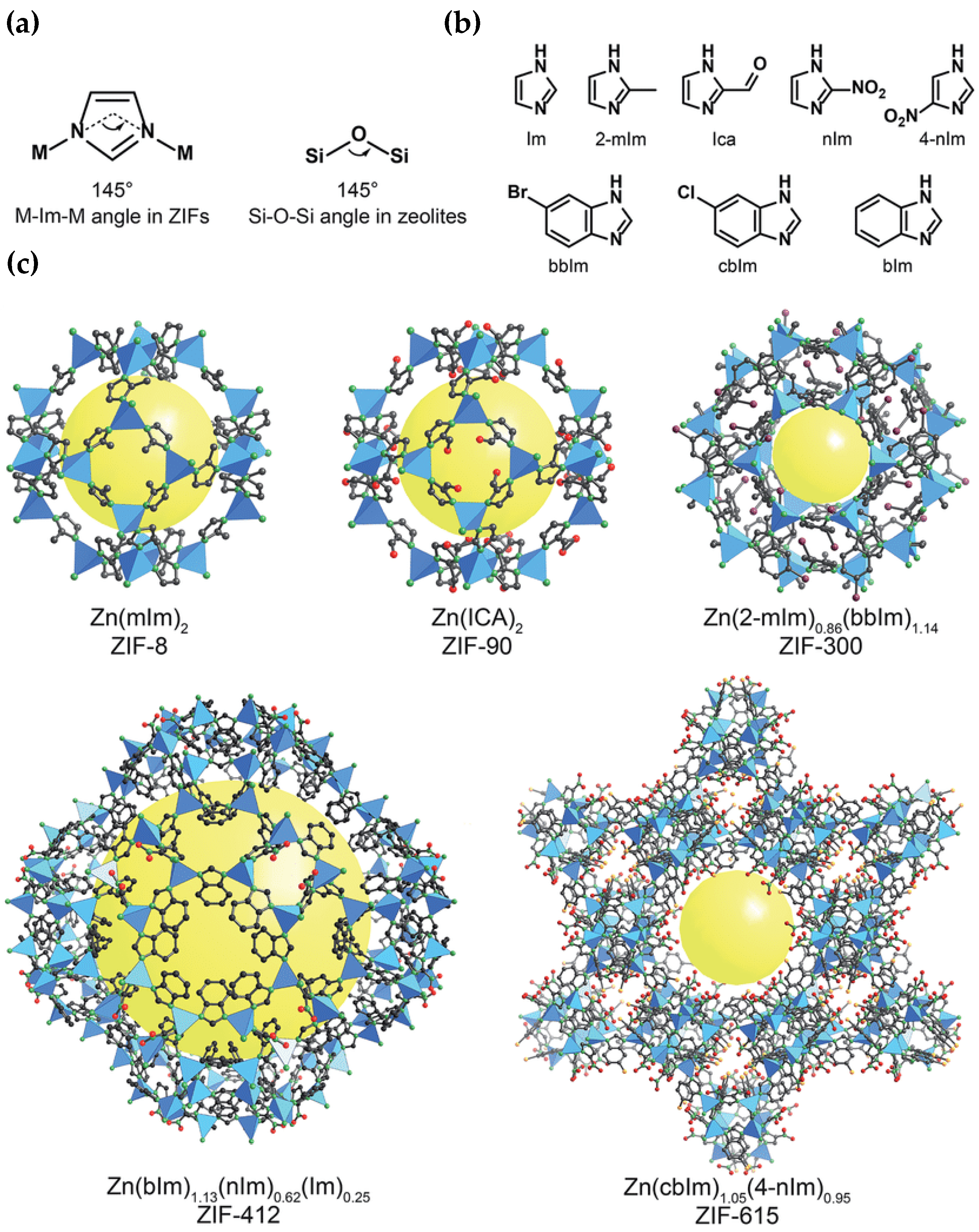
Hybrid materials, which are also known as metal–organic frameworks (MOFs).
Among the aforementioned materials, recent progress focuses mainly on the development and integration of metal–organic frameworks (MOFs) and carbon molecular sieves (CMSs) into novel MMMs. Other types of MMMs, which are increasingly examined for their potential to improve CO2 separation, include nanocomposite membranes, which employ nano-sized fillers (of various materials); ionic liquid (IL)-based membranes, which employ ionic liquids as the continuous phase in the fabricated MMMs; and facilitated transport membranes (FTMs), where the gas diffusion mechanism is based on facilitated transport.

5.1. Metal–Organic Framework (MOF) Membraness

Metal–organic frameworks (MOFs) comprise a new kind of porous materials, which are constructed from multidentate organic ligands and metal ions. In comparison with typical porous materials, e.g., zeolites and carbon nanotubes, MOFs can provide an ideal platform for gas absorption and separation, drug delivery, catalysts, electrode materials and semi-conductors due to their well-ordered architecture. MOFs present characteristics such as tunable pore size, large surface area and chemistry, which are favorable for gas separation and for unlocking efficient CO2 capture paths [101].
Apart from the development of typical fabrication techniques for MOF-based membranes, membranes that combine MOFs with other materials have also been generated in recent years. MOF membranes, which usually have a thickness of micrometers, present high mechanical stability; however, they have low separation performance due to high mass transfer resistances and result in low permeabilities. To deal with this drawback, ultrathin two-dimensional monolayer MOF membranes with a thickness of nanometers have been proposed [102,103]. Yao et al. (2023) [104] employed an anodic electrodeposition method to incorporate in situ different kinds of MOFs (HKUST-1, Cu-BDC and Cu-BDC-NH2) into the nanochannels of graphene oxide (GO), aiming to result in the formation of a new layer-by-layer structure confined by GO layers. The pore-size distribution of the obtained membranes was wider, and a significant increase in elastic modulus and hardness was observed. The membranes also presented high CO2 capture capacity and selectivity, providing a promising strategy to produce functional and mechanically strong MOFs for real-field applications. One of the most representative MOFs, which presents high affinity for CO2 due to its abundant CO2-philic groups and sites, is zeolitic imidazolate framework-8 (ZIF-8) (Figure 9). ZIF-8 was incorporated as a filler by Wang et al. (2024) [105] into a Pebax matrix (60 wt % polyethylene oxide and 40 wt % polyamide 6), and the obtained MMM achieved enhanced CO2 separation performance. Other novel MOF-based membranes, which offer significant benefits, e.g., enhanced separation performance, defect-free structures and improved mechanical properties, include ionic liquid (IL)-MOF membranes, covalent organic framework (COF)-MOF membranes and MOF-glass membranes [106].

5.2. Carbon Molecular Sieve (CMS) Membranes

Carbon molecular sieves (CMSs) are a type of activated carbons with pores of a very low (molecule) size, which have been utilized for separating O2 from air and CO2 during biogas upgrading. However, they are much less investigated for CO2/N2 separation and carbon capture from flue gases [108]. The rigid pore structure of CMS membranes presents a bi-modal pore-size distribution, where the micropores (7–20 Å) improve gas permeability and the ultra-micropores (<7 Å) enhance gas selectivity through molecular sieving. Due to these properties, CMS membranes are often utilized for separating gases with similar molecular kinetic diameters [109,110]. CMS membranes have attracted worldwide attention as they exhibit higher chemical and thermal stability and enhanced gas separation performance compared to polymeric membranes. Several polymers are used to synthesize CMS membranes, such as polyimides, phenol formaldehyde, cellulose, poly(phenylene oxide), sol–gel polymers, poly(vinylidene chloride-co-vinyl chloride) and poly(furfuryl alcohol). Among the aforementioned materials, poly(furfuryl alcohol) is considered a strong possible precursor for manufacturing high-performance CMS membranes [111,112].
The development of MMMs which contain CMSs has been examined by various researchers. A suitable filler must withstand high temperatures and be easy to prepare, taking into account the preparation conditions of CMS membranes and the demand for economic efficiency [113]. Li et al. (2019) [114] adopted the strategy of filler design optimization with membrane carbonization to produce mixed-matrix CMS membranes incorporating a hierarchical zeolite 5A filler (Figure 10). Apart from its intrinsic micropores, the hierarchical filler also possessed mesopores of ∼8 nm that offered additional transport pathways to facilitate the diffusion of CO2 through the membrane carbon matrix. More recently, Zhang et al. (2023) [113] incorporated the zeolite ZSM-5 into the carbon matrix of a CMS membrane to fabricate a CMS/ZSM-5 MMM. The results showed that the gas permeabilities of CMS/ZSM-5 MMM for H2, CO2, O2, N2 and CH4 were significantly improved in comparison with the pure CMS membranes.

5.3. Nanocomposite Membranes

When the incorporated inorganic material (filler) is of nano-scale size, the obtained MMMs are also known as nanocomposite membranes. Nanofillers (usually between 1 and 100 nm) are increasingly incorporated in polymeric matrices to produce MMMs in recent years. Nanofillers present molecular sieving ability, an arranged pore structure, good mechanical properties and thermal stability, and their exceptional interfacial compatibility forms special nano-channels for the transportation of CO2 when they are combined with polymers. Nanofillers in MMMs are used to decrease the gas transport resistance and enlarge the chain spacing in the polymer. In addition, they increase CO2 solubility in MMMs, while the sieving ability of their porous structure improves significantly the gas selectivity and permeability [95].
Based on the number of dimensions, nanofillers (and their respective MMMs) can be zero-dimensional (0D), one-dimensional (1D), two-dimensional (2D) and three-dimensional (3D) (Figure 11). Zero-dimensional nanofillers are typically represented by nanoparticles, which include mainly gold, zinc, silver or metal oxides with a pore size of 1–50 nm usually. One-dimensional nanotubes, nano-wires, nano-rods and nano-fibers are nanomaterials of ‘needle’ shape, while two-dimensional nanomaterials are thin nanosheets with only one external nano-scale dimension. Two-dimensional nanomaterials can reach a few square microns, usually far exceeding their thicknesses. Nanoporous materials, such as zeolites, silicalites and MOFs of polycrystalline structures can be regarded as 3D nanofillers. It must be mentioned that bulk nanoparticles and bundles of 1D materials and multi-nanolayers are also regarded as 3D nanomaterials and, therefore, exhibit tunable properties based on their dispersion state [115].
In recent years, various research studies have investigated the fabrication and utilization of nanocomposite membranes for efficient CO2 capture. Dai et al. (2023) [116] demonstrated that the addition of one-dimensional carboxymethylcellulose (CMC) between 2D g-C3N4 nanosheets is a promising material for CO2 separation membranes. Using the electrostatic self-assembly method, Zhao et al. (2023) [101] synthesized novel porous amino-functionalized nanosheets with polyethyleneimine (PEI-F-Ce) and combined them with a polyethylene oxide (PEO) matrix to fabricate an MMM (XLPEO/PEI-F-Ce) of high CO2/N2 selectivity. It was shown that XLPEO/PEI-F-Ce selectivity was significantly enhanced due to the combined improvement in solubility and reaction selectivity. Maleh et al. (2022) [117] suggested a novel polyethersulfone (PES)-based MMM for separating CO2 from natural gases and flue gases. These researchers also studied how polyurethane (PU) and clay nano-sheets affect the structure and the separating properties of three MMMs that were based on PES, and showed that the incorporation of PU and clay nano-sheets into the PES matrix significantly improved its gas permeation and separation properties.

5.4. Ionic Liquid (IL)-Based Membranes

Ionic liquids (ILs) are molten organic salts in liquid form, with typical melting points lower than 100 °C [118]. ILs are attracting attention in solvent-based post-combustion CO2 capture because they present some remarkable characteristics, such as high thermal stability, flammability and low volatility with huge tunability when selecting cations and anions. Due to these properties, high CO2 solubility and high separation potential for specific gas molecules can be achieved. However, pure ILs present a small surface area and a limited capacity for CO2 capture [119]. Recently, the combination of ILs with membranes has been reported as a potential separation system. With membrane support, an IL can keep its solvent properties and, consequently, improve its gas separation efficiency. Several distinct types of membrane processes combined with ILs have been investigated, including supported ionic liquid membranes (SILMs), IL composite polymer membranes (ILPMs), IL composite mixed-matrix membranes (ILMMM), poly(ionic liquid) membranes (PILMs), IL gel membranes (ILGMs) and IL membrane contactors (ILMCs). These systems have shown high gas separation efficiency [120].
In recent years, the number of research studies which employ ILs for the fabrication of MMMs with enhanced CO2 separation characteristics has increased. Mahboubi et al. (2023) [118] combined 1-butyl-3-methylimidazolium acetate, as an ionic liquid, with a polyether-block-amide polymer and aluminium oxide (Al2O3) nanoparticles, and prepared a novel ternary MMM with improved permeability and selectivity for CO2. Nabais et al. (2022) [121] also suggested the incorporation of different azo-porous organic polymers (azo-POPs) (Figure 12), as fillers, into ion gels with a high IL content (80 wt %) for the fabrication of MMMs with enhanced CO2 separation characteristics. Ahmad et al. (2018, 2021) [122,123] successfully employed an IL as the continuous phase in an MMM and enhanced its CO2 separation performance. According to Sanni et al. (2022) [120], among the membrane–ionic liquid systems, a hybrid system that is comprised of cellulose acetate, methyl ammonium nitrate and graphene oxide (CA-methyl ammonium nitrate-GO) is a possible candidate with high CO2 capture (>80%) due to its enhanced porosity, mechanical and thermal stability, good selectivity and low CO2 permeability.

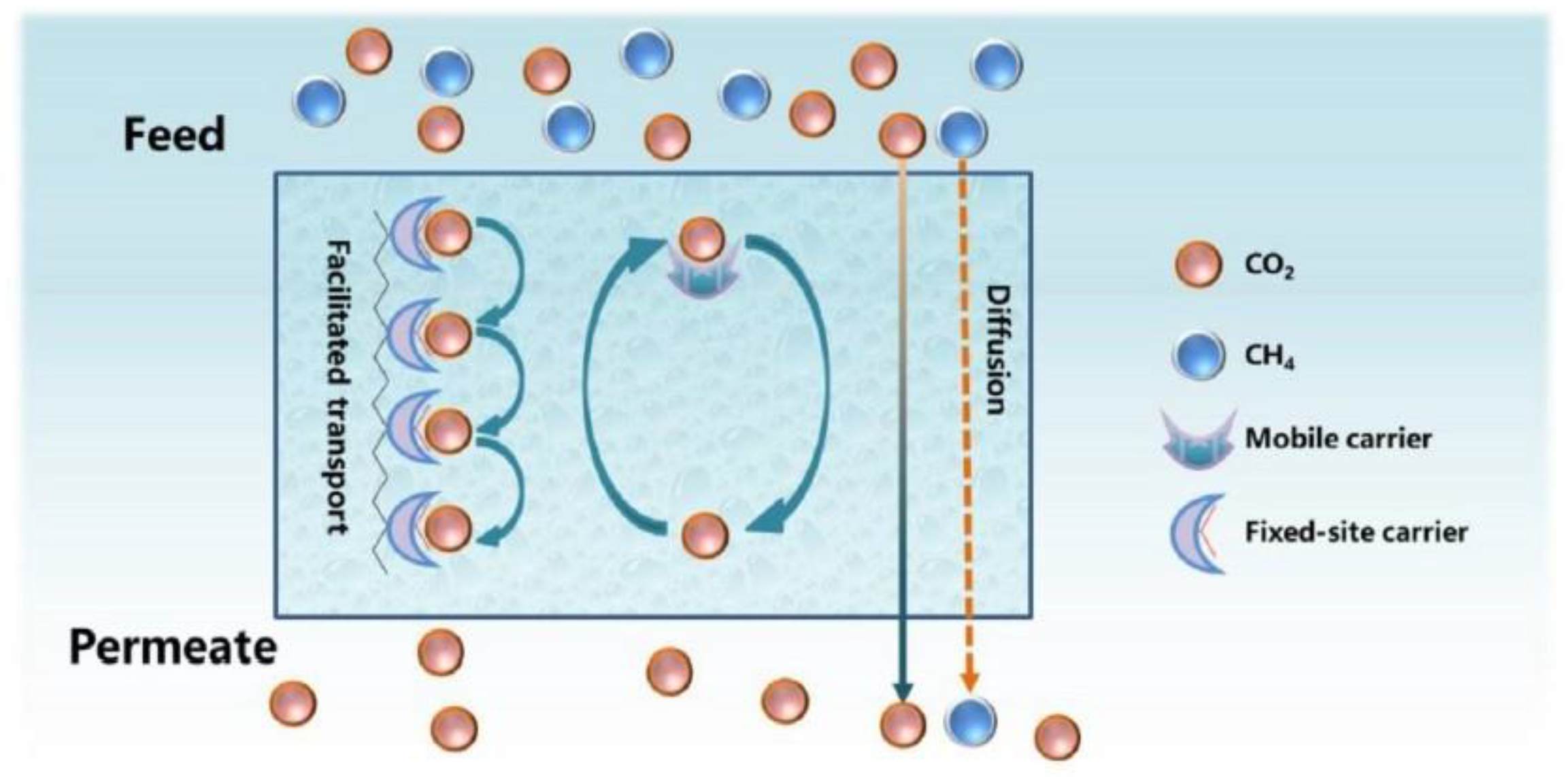
5.5. Facilitated Transport Membranes (FTMs)

When CO2 permeates through a membrane, different transport mechanisms can take place, such as solution diffusion, Knudsen diffusion, convective diffusion, capillary condensation, molecular sieving and facilitated transport. In polymeric membranes, apart from the solution-diffusion mechanism, which is a common gas diffusion mechanism, especially in non-porous polymers, CO2 transport can be facilitated via reversible chemical reactions between CO2 and specific molecules (carriers) (Figure 13) [124]. These membranes, which are known as facilitated transport membranes (FTMs), can reversibly interact with CO2 and, thus, provide an ‘extra’ mechanism to promote its transport, while other components exclusively pass through the solution-diffusion model [60,94]. FTMs have shown great potential for superior gas separation performance and specifically for CO2 capture [125]. Through the incorporation of carrier agents into the polymer matrices to react with CO2 reversibly, FTMs provide high flux and selectivity. Mobile carriers and fixed carriers are the two predominant FTM types. A mobile carrier is also called a supported liquid membrane (SLM) or an ‘immobilized’ liquid membrane (ILM). This carrier initially reacts with CO2 on the feed side, and the subsequent product moves across the membrane. On the permeate side, CO2 is released and H2 (or other gas species) is not influenced by the facilitated transport. A fixed carrier, which is bonded covalently to the polymer backbone, has limited mobility. Each CO2 molecule reacts with one carrier site and then passes to the next site until it reaches the permeate side [95,126].
Researchers have made attempts to establish FTMs in two directions: (i) development of innovative carriers that present high diffusivity and reactivity with CO2, and (ii) development of low-cost membranes that present very high selectivity. Stability in long-term operation is also necessary as membranes can be exposed to flue gases with NOx and SO2 impurities. Until now, only a small number of polymeric membranes have shown to be efficient for CO2 capture, especially in pilot plants. Polyvinylamine (PVAm), which is a weak linear cationic polyelectrolyte that contains many primary amine groups, is widely reported as appropriate for facilitated CO2 transportation following various pathways with the presence of water [96,127]. Janakiram et al. (2019) [128] used an FTM that consists of a selective layer based on the blend of polyvinyl alcohol (PVA) with sterically hindered PVAm, and achieved 652 GPU of CO2 permeance, but a rather low CO2/N2 selectivity (41.3). In the following years, they scaled up and used three different hollow fiber FTMs with real flue gases from a cement plant [129] and simulated a two-stage membrane process using different classes of facilitated transport membranes, which were previously validated in industrial conditions, with promising results [130]. Wu et al. (2023) [66] also developed SW membrane modules for industrial use with an effective membrane area of 31 m2. The employed modules consisted of amine-based facilitated transport PVAm multilayer composite membranes, which were fabricated using roll-to-roll coating equipment. The results showed that a reduction in operating pressure increased the purity of CO2 but decreased the CO2 capture rate, and there was a trade-off between the power consumption and the membrane area demand. However, although PVAm-based modules have proven to be competitive, compared to most amine-based technologies, the difficulty in maintaining high performance in larger plants still prevents their full-scale application. Aiming to increase the mechanical strength of membranes, the main constituents of polymers coupled with other polymers or nanofillers, carbon nanotubes and metal–organic frameworks (MOFs) are also considered in FTMs [96].

6. Commercially Applied Membrane Modules for Industrial CO2 Capture

Three commercial membrane modules have been successfully demonstrated at a relatively high TRL (5–7) for post-combustion capturing of CO2 from flue gases of fossil fuel-fired and cement facilities: PolarisTM, PolyActiveTM and PRISMTM modules [131].
PolarisTM, which was developed by Membrane Technology and Research (MTR) (USA), has been broadly examined and assessed for capturing CO2 from flue gases of coal-fired power plants. PolarisTM Gen 1, which presents a CO2 permeance of 1000 GPU and a CO2/N2 selectivity of 50, has been tested commercially already [132,133,134]. During the years 2012–2015, PolarisTM spiral-wound membranes exhibited prolonged membrane performance (>111,000 h) and achieved >90% CO2 capture on a bench scale (0.05 MWe or 1 tons of CO2/day). A larger pilot-scale system (1 MWe or 20 tons of CO2/day) also presented stable operation (>6 months), achieving 90% CO2 capture. In this unit, a plate-and-frame module with low-pressure drop, increased packing density and lower power cost (~10 MWe saving) was successfully operated as well. Polaris Gen 2, with twice the CO2 permeance but similar CO2/N2 selectivity, showed higher CO2 separation performance (60–70%), compared to Gen 1, and also exhibited stable performance for >40 h when it was tested on a laboratory scale. These efforts from MTR have advanced this membrane technology from TRL 2–3 to TRL 6. Aiming to capture 200 tons of CO2 per day from a coal-fired power plant, a large pilot system is under design with an expected CO2 purity > 99%. After the successful operation of such a plant, the commercial maturity of this membrane technology for CO2 capture is expected to increase to TRL 8. Finally, PolarisTM membrane performance exhibited high stability (>168 h) during real field tests in 2021 at Jiangyou Power Plant (Jiangyou, China), which operated under dynamic conditions (power plant load ranged between 54 and 84%). The aforementioned results confirm the efficiency of PolarisTM modules under varying operating conditions [32,135].
Helmholtz-Zentrum Geesthacht (Geesthacht, Germany) developed PolyActiveTM module, which showed high CO2 permeance, namely 3068 m3 (STP)/m2/h/bar (1136 GPU), and high CO2/N2 selectivity (60), with a CO2 recovery of 42.7% and a CO2 purity of 68.2% [32,136]. Nowadays, PolyActive™ membranes are broadly applied. Brinkman et al. [137] showed how temperature affects the transport properties of different multilayer PolyActive™ membranes; temperature increased permeance but decreased selectivity. At the optimal temperature (~40 °C), the permeance reached 2000 GPU and the CO2/N2 selectivity was almost 45. More information about the mechanical properties of PolyActive™ membranes (structure and thickness) is presented in the work by Schuldt et al. [138]. It was shown that when CO2 pressure is >8 bar, PolyActive™ swells with CO2, resulting in lower selectivity [13,138].
PRISM™ module, developed by the company Air Products (Allentown, PA, USA), was employed by Scholes et al. [139] at a Victorian brown coal-fired power plant. Initially, the pressure of the flue gas was increased to 150 kPa. The dried flue gas entered the membrane at 45 °C and 3.5 kg/h. After the blower discharge of a direct contact cooler, the module was placed under clean flue gas. However, water condensation on the membrane was the most important drawback of the process. Both selectivity and permeance were greatly reduced after a few hours of operation, which was attributed to membrane plasticization and swelling by water. After some time of operation, they increased slightly, but not up to the initial values. Apart from CO2, impurities of NOx and SO2 also passed through the membrane. Scholes et al. [139] concluded that the main challenge was the fluctuations in humidity and the challenging regulation of the experimental setup in terms of temperature control. Due to humidity, significant changes can happen in membrane transport properties [13].

7. Main Challenges and Future Perspectives

With the exception of some gas-sweetening membrane systems that are currently commercialized, the widespread application of membranes is still limited, and a significant gap is observed between lab-scale research and real field applications. Current commercial membrane modules present low selectivity, and multiple stages are needed to achieve the necessary CO2 purity [96,140]. Apart from the inevitable trade-off between selectivity and permeability, which still remains an important limitation in membrane separation technologies [14], a major challenge in coal-fired power plants is the low CO2 concentration (10–15%) in the emitted flue gases [141]. For these flue gases, commercial membranes cannot achieve the required CO2 selectivity and purity, illustrating the need for advanced, novel membranes [10]. Regarding the application of mixed-matrix membranes (MMMs) for CO2 capture, the main challenges include potential interfacial defects between the polymeric and inorganic phases, particle agglomeration, sedimentation and poor dispersion, which can decrease membrane selectivity. Apart from the size and amount of the employed particles, attention should be also given to chain rigidification, adhesion between particles and the polymer phase, viscosity of dope-containing particles and the applied stress to induce particle dispersion, which can influence the overall MMM performance [7,142]. The challenges that prevent the broad commercialization and application of membranes for carbon capture can be summarized into three categories, according to Olabi et al. (2023) [143]: economic/financial, technical and social (Figure 14).
Nevertheless, the number of membrane technologies for CO2 capture is expected to increase in the future in view of the benefits of low energy consumption, low capital and operating costs, low space requirements, avoidance of chemicals/harmful wastes and simple operation. Future research should focus on the improvement in separation process efficiency and the reduction in capital and operating costs, which will facilitate the use of membranes by interested stakeholders. To make membrane-based technologies cost-effective during carbon capture, further advancements are required in membrane fabrication with novel or composite materials (composed of two or more species), which will enhance the intrinsic and surface properties and, therefore, the selectivity and permeability of the produced membrane modules. It is also understood that the produced MMMs should be compatible with different flue gas compositions, apart from their increased selectivity. Although there are numerous studies concerning the use of MMMs for CO2 capture, industrial engineering is still in its infancy and the efforts to create new filler materials will be continued. Finally, the industrialization of MMMs for carbon capture will necessitate the utilization of low-cost, renewable and, if possible, naturally occurring polymers; the manufacturing and reproducibility of thin, defect-free bio-polymeric MMMs that will replace synthetic membranes is very challenging.

8. Conclusions

The most common post-combustion CO2 capture technologies are chemical absorption, adsorption, cryogenic separation and membrane separation. Membrane separation is increasingly implemented in recent years due to low capital and operating costs, low energy consumption and space requirements, easy operation, simple equipment, high flexibility, safety and an absence of possibly toxic or harmful wastes. The latest advancements in membrane technologies for CO2 capture emphasize primarily the fabrication of novel membranes with enhanced properties that will achieve higher selectivity, permeability, mechanical strength and potential for large-scale preparation. The majority of these membranes are composite or mixed-matrix membranes (MMMs), which are fabricated via the integration of novel inorganic materials (fillers) into the structure of polymeric membrane materials. Among these materials, recent progress focuses mainly on the utilization of metal–organic frameworks (MOFs), such as zeolitic imidazolate frameworks (ZIFs) and carbon molecular sieves (CMSs), i.e., activated carbons with molecule-sized pores. Other types of MMMs, which are increasingly examined for their potential to improve CO2 separation, include nanocomposite membranes, which employ nano-sized fillers of various materials; ionic liquid (IL)-based membranes, which employ ionic liquids as the continuous phase in the fabricated MMM; and facilitated transport membranes (FTMs), where the gas diffusion mechanism is based on facilitated transport.

Funding

This research received no external funding.

Data Availability Statement

No new data were created.

Acknowledgments

The present work is part of the “Demonstration of a mobile unit for hybrid energy storage based on CO2 capture and renewable energy sources (LIFE CO2toCH4)” project, which received funding from the LIFE Programme of the European Union.

Conflicts of Interest

The authors declare no conflict of interest.

References

  1. Chakrabortty, S.; Kumar, R.; Nayak, J.; Jeon, B.-H.; Dargar, S.K.; Tripathy, S.K.; Pal, P.; Ha, G.-S.; Kim, K.K.; Jasiński, M. Green synthesis of MeOH derivatives through in situ catalytic transformations of captured CO2 in a membrane integrated photo-microreactor system: A state-of-art review for carbon capture and utilization. Renew. Sust. Energ. Rev. 2023, 182, 113417. [Google Scholar] [CrossRef]
  2. Wu, H.; Li, Q.; Sheng, M.; Wang, Z.; Zhao, S.; Wang, J.; Mao, S.; Wang, D.; Guo, B.; Ye, N.; et al. Membrane technology for CO2 capture: From pilot-scale investigation of two-stage plant to actual system design. J. Membr. Sci. 2021, 624, 119137. [Google Scholar] [CrossRef]
  3. Liu, Y.; Ren, Y.; Ma, H.; He, G.; Jiang, Z. Advanced organic molecular sieve membranes for carbon capture: Current status, challenges and prospects. Adv. Membr. 2022, 2, 100028. [Google Scholar] [CrossRef]
  4. Tao, Y.R.; Xu, H.J. A critical review on potential applications of Metal-Organic frameworks (MOFs) in adsorptive carbon capture technologies. Appl. Therm. Eng. 2024, 236, 121504. [Google Scholar] [CrossRef]
  5. Langie, K.M.G.; Tak, K.; Kim, C.; Lee, H.W.; Park, K.; Kim, D.; Jung, W.; Lee, C.W.; Oh, H.-S.; Lee, D.K.; et al. Toward economical application of carbon capture and utilization technology with near-zero carbon emission. Nat. Commun. 2022, 13, 7482. [Google Scholar] [CrossRef]
  6. Odunlami, O.A.; Vershima, D.A.; Oladimeji, T.E.; Nkongho, S.; Ogunlade, S.K.; Fakinle, B.S. Advanced techniques for the capturing and separation of CO2—A review. Results Eng. 2022, 15, 100512. [Google Scholar] [CrossRef]
  7. Katare, A.; Kumar, S.; Kundu, S.; Sharma, S.; Kundu, L.M.; Mandal, B. Mixed Matrix Membranes for Carbon Capture and Sequestration: Challenges and Scope. ACS Omega 2023, 8, 17511–17522. [Google Scholar] [CrossRef]
  8. Zanco, S.E.; Pérez-Calvo, J.-F.; Gasós, A.; Cordiano, B.; Becattini, B.; Mazzotti, M. Post-combustion CO2 Capture: A Comparative Techno-Economic Assessment of Three Technologies Using a Solvent, an Adsorbent, and a Membrane. ACS Engin. Au 2021, 1, 50–72. [Google Scholar] [CrossRef]
  9. Ngu, L.H. Carbon Capture Technologies. In Reference Module in Earth Systems and Environmental Sciences; Elsevier: Amsterdam, The Netherlands, 2022. [Google Scholar]
  10. Kim, S.; Scholes, C.A.; Heath, D.E.; Kentish, S.E. Gas-liquid membrane contactors for carbon dioxide separation: A review. Chem. Eng. J. 2021, 41, 128468. [Google Scholar] [CrossRef]
  11. Sun, S.; Billings, A.; Zhang, K.; Huang, K. Direct, efficient and selective capture of low concentration of CO2 from natural gas flue gas using a high temperature tubular carbon capture membrane. J. Membr. Sci. 2022, 661, 120929. [Google Scholar] [CrossRef]
  12. Gkotsis, P.; Kougias, P.; Mitrakas, M.; Zouboulis, A. Biogas upgrading technologies—Recent advances in membrane-based processes. Int. J. Hydrogen Energy 2023, 48, 3965–3993. [Google Scholar] [CrossRef]
  13. Kárászová, M.; Zach, B.; Petrusová, Z.; Červenka, V.; Bobák, M.; Šyc, M.; Izák, P. Post-combustion carbon capture by membrane separation, Review. Sep. Purif. Technol. 2020, 238, 116448. [Google Scholar] [CrossRef]
  14. Da Conceicao, M.; Nemetz, L.; Rivero, J.; Hornbostel, K.; Lipscomb, G. Gas Separation Membrane Module Modeling: A Comprehensive Review. Membranes 2023, 13, 639. [Google Scholar] [CrossRef]
  15. Singh, P.; Shah, S.; Rai, S.K. Post-combustion carbon capture by polymeric membrane: A review. Mater. Today Proc. 2022, 62, 318–324. [Google Scholar] [CrossRef]
  16. Favre, E. Membrane Separation Processes and Post-Combustion Carbon Capture: State of the Art and Prospects. Membranes 2022, 12, 884. [Google Scholar] [CrossRef]
  17. Dowson, G.; Styring, P. Chapter 9—Conversion of Carbon Dioxide to Oxygenated Organics. In Carbon Dioxide Utilisation; Elsevier: Amsterdam, The Netherlands, 2015; pp. 141–159. [Google Scholar]
  18. Ericsson, K. Biogenic carbon dioxide as feedstock for production of chemicals and fuels: A techno-economic assessment with a European perspective. In IMES/EESS Report No 103; Lund University Publications: Lund, Sweden, 2017. [Google Scholar]
  19. IPCC. IPCC Special Report on Carbon Dioxide Capture and Storage (Chapter 3); Cambridge University Press: Cambridge, UK, 2005. [Google Scholar]
  20. Kanniche, M.; Gros-Bonnivard, R.; Jaud, P.; Valle-Marcos, J.; Amann, J.-M.; Bouallou, C. Pre-combustion, post-combustion and oxy-combustion in thermal power plant for CO2 capture. Appl. Therm. Eng. 2010, 30, 53–62. [Google Scholar] [CrossRef]
  21. Kheirinik, M.; Ahmed, S.; Rahmanian, N. Comparative Techno-Economic Analysis of Carbon Capture Processes: Pre-Combustion, Post-Combustion, and Oxy-Fuel Combustion Operations. Sustainability 2021, 13, 13567. [Google Scholar] [CrossRef]
  22. De Mello, L.F.; Gobbo, R.; Moure, G.T.; Miracca, I. Oxy-combustion technology development for fluid catalytic crackers (FCC)—Large pilot scale demonstration. Energy Procedia 2023, 37, 7815–7824. [Google Scholar] [CrossRef]
  23. Khan, U.; Ogbaba, C.C.; Abiodun, O.-A.O.; Adeleke, A.A.; Ikubanni, P.P.; Okoye, P.U.; Okolie, J.A. Assessing absorption-based CO2 capture: Research progress and techno-economic assessment overview. Carbon Capture Sci. Technol. 2023, 8, 100125. [Google Scholar] [CrossRef]
  24. Mukherjee, A.; Okolie, J.A.; Abdelrasoul, A.; Niu, C.; Dalai, A.K. Review of post-combustion carbon dioxide capture technologies using activated carbon. J. Environ. Sci. 2019, 83, 46–63. [Google Scholar] [CrossRef]
  25. Wang, X.; Song, C. Carbon Capture from Flue Gas and the Atmosphere: A Perspective. Front. Energy Res. 2020, 8, 560849. [Google Scholar] [CrossRef]
  26. Spigarelli, B.P.; Kawatra, S.K. Opportunities and challenges in carbon dioxide capture. J. CO2 Util. 2013, 1, 69–87. [Google Scholar] [CrossRef]
  27. Khalifa, O.; Alkhatib, I.I.I.; Bahamon, D.; Alhajaj, A.; Abu-Zahra, M.R.M.; Vega, L.F. Modifying absorption process configurations to improve their performance for Post-Combustion CO2 capture—What have we learned and what is still Missing? Chem. Eng. J. 2022, 430, 1330996. [Google Scholar] [CrossRef]
  28. Oexmann, J.; Kather, A.; Linnenberg, S.; Liebenthal, U. Post-combustion CO2 capture: Chemical absorption processes in coal-fired steam power plants. Greenh. Gases Sci. Technol. 2012, 2, 80–98. [Google Scholar] [CrossRef]
  29. Ghiat, I.; Al-Ansari, T. A review of carbon capture and utilization as a CO2 abatement opportunity within the EWF nexus. J. CO2 Util. 2021, 45, 101432. [Google Scholar] [CrossRef]
  30. Wang, Y.; Zhao, L.; Otto, A.; Robinius, M.; Stolten, D. A Review of Post-combustion CO2 Capture Technologies from Coal-fired Power Plants. Energy Procedia 2017, 114, 650–665. [Google Scholar] [CrossRef]
  31. Song, C.; Liu, Q.; Deng, S.; Li, H.; Kitamura, Y. Cryogenic-based CO2 capture technologies: State-of-the-art developments and current challenges. Renew. Sust. Energ. Rev. 2019, 101, 265–278. [Google Scholar] [CrossRef]
  32. Hou, R.; Fong, C.; Freeman, B.D.; Hill, M.R.; Xie, Z. Current status and advances in membrane technology for carbon capture. Sep. Purif. Technol. 2022, 300, 121863. [Google Scholar] [CrossRef]
  33. Hongjun, Y.; Shuanshi, F.; Xuemei, L.; Yanhong, W.; Jianghua, N. Economic Comparison of Three Gas Separation Technologies for CO2 Capture from Power Plant Flue Gas. Chin. J. Chem. Eng. 2011, 19, 615–620. [Google Scholar]
  34. Lin, Q.; Zhang, X.; Wang, T.; Zheng, C.; Gao, X. Technical Perspective of Carbon Capture, Utilization, and Storage. Engineering 2022, 14, 27–32. [Google Scholar] [CrossRef]
  35. Arshad, N.; Alhajaj, A. Process synthesis for amine-based CO2 capture from combined cycle gas turbine power plant. Energy 2023, 274, 127391. [Google Scholar] [CrossRef]
  36. Artanto, Y.; Jansen, J.; Pearson, P.; Do, T.; Cottrell, A.; Meuleman, E.; Feron, P. Performance of MEA and amine-blends in the CSIRO PCC pilot plant at Loy Yang Power in Australia. Fuel 2012, 101, 264–275. [Google Scholar] [CrossRef]
  37. Wang, M.; Lawal, A.; Stephenson, P.; Sidders, J.; Ramshaw, C. Post-combustion CO2 capture with chemical absorption: A state-of-the-art review. Chem. Eng. Res. Des. 2011, 89, 1609–1624. [Google Scholar] [CrossRef]
  38. Zhao, B.; Liu, F.; Cui, Z.; Liu, C.; Yue, H.; Tang, S. Enhancing the energetic efficiency of MDEA/PZ-based CO2 capture technology for a 650 MW power plant: Process improvement. Appl. Energy 2017, 185, 362–375. [Google Scholar] [CrossRef]
  39. Li, K.; Leigh, W.; Feron, P.; Yu, H.; Tade, M. Systematic study of aqueous monoethanolamine (MEA)-based CO2 capture process: Techno-economic assessment of the MEA process and its improvements. Appl. Energy 2016, 165, 648–659. [Google Scholar] [CrossRef]
  40. Raynal, L.; Bouillon, P.A.; Gomez, A.; Broutin, P. From MEA to demixing solvents and future steps, a roadmap for lowering the cost of post-combustion carbon capture. Chem. Eng. J. 2011, 171, 742–752. [Google Scholar] [CrossRef]
  41. Rao, A.B.; Rubin, E.S. A technical, economic, and environmental assessment of amine-based CO2 capture technology for power plant greenhouse gas control. Environ. Sci. Technol. 2002, 36, 4467–4475. [Google Scholar] [CrossRef] [PubMed]
  42. Braakhuis, L.; Knuutila, H.N. Predicting solvent degradation in absorption-based CO2 capture from industrial flue gases. Chem. Eng. Sci. 2023, 279, 118940. [Google Scholar] [CrossRef]
  43. Raganati, F.; Chirone, R.; Ammendola, P. CO2 Capture by Temperature Swing Adsorption: Working Capacity as Affected by Temperature and CO2 Partial Pressure. Ind. Eng. Chem. Res. 2020, 59, 3593–3605. [Google Scholar] [CrossRef]
  44. Zeng, H.; Qu, X.; Xu, D.; Luo, Y. Porous Adsorption Materials for Carbon Dioxide Capture in Industrial Flue Gas. Front. Chem. 2022, 10, 939701. [Google Scholar] [CrossRef]
  45. Guo, Z.; Deng, S.; Li, S.; Lian, Y.; Zhao, L.; Yuan, X. Entropy Analysis of Temperature Swing Adsorption for CO2 Capture Using the Computational Fluid Dynamics (CFD) Method. Entropy 2019, 21, 285. [Google Scholar] [CrossRef] [PubMed]
  46. Akdag, A.S.; Durán, I.; Gullu, G.; Pevida, C. Performance of TSA and VSA post-combustion CO2 capture processes with a biomass waste-based adsorbent. J. Environ. Chem. Eng. 2022, 10, 108759. [Google Scholar] [CrossRef]
  47. Golmakani, A.; Fatemi, S.; Tamnanloo, J. Investigating PSA, VSA, and TSA methods in SMR unit of refineries for hydrogen production with fuel cell specification. Separ. Purif. Technol. 2017, 176, 73–91. [Google Scholar] [CrossRef]
  48. Dhoke, C.; Cloete, S.; Krishnamurthy, S.; Seo, H.; Luz, I.; Soukri, M.; Park, Y.-k.; Blom, R.; Amini, S.; Zaabout, A. Sorbents screening for post-combustion CO2 capture via combined temperature and pressure swing adsorption. Chem. Eng. J. 2020, 380, 122201. [Google Scholar] [CrossRef]
  49. Gunawardene, O.H.P.; Gunathilake, C.A.; Vikrant, K.; Amaraweera, S.M. Carbon Dioxide Capture through Physical and Chemical Adsorption Using Porous Carbon Materials: A Review. Atmosphere 2022, 13, 397. [Google Scholar] [CrossRef]
  50. Rashidi, N.A.; Yusup, S. An overview of activated carbons utilization for the post-combustion carbon dioxide capture. J. CO2 Util. 2016, 13, 1–16. [Google Scholar] [CrossRef]
  51. Karimi, M.; Shirzad, M.; Silva, J.A.C.; Rodrigues, A.E. Carbon dioxide separation and capture by adsorption: A review. Environ. Chem. Lett. 2023, 21, 2041–2084. [Google Scholar] [CrossRef]
  52. Lai, J.Y.; Ngu, L.H.; Hashim, S.S. A review of CO2 adsorbents performance for different carbon capture technology processes conditions. Greenh. Gases Sci. Technol. 2021, 11, 1076–1117. [Google Scholar] [CrossRef]
  53. Raganati, F.; Miccio, F.; Ammendola, P. Adsorption of Carbon Dioxide for Post-combustion Capture: A Review. Energy Fuels 2021, 35, 12845–12868. [Google Scholar] [CrossRef]
  54. Aneesh, A.M.; Sam, A.A. A mini-review on cryogenic carbon capture technology by desublimation: Theoretical and modeling aspects. Front. Energy Res. 2023, 11, 1167099. [Google Scholar] [CrossRef]
  55. Knapik, E.; Kosowski, P.; Stopa, J. Cryogenic liquefaction and separation of CO2 using nitrogen removal unit cold energy. Chem. Eng. Res. Des. 2018, 131, 66–79. [Google Scholar] [CrossRef]
  56. Mokhatab, S.; Poe, W.A.; Mak, J.Y. Chapter 7—Natural Gas Treating. In Handbook of Natural Gas Transmission and Processing—Principles and Practices, 4th ed.; Elsevier: Amsterdam, The Netherlands, 2019. [Google Scholar]
  57. Liu, B.; Yang, X.; Chiang, P.-C.; Wang, T. Energy Consumption Analysis of Cryogenic-membrane Hybrid Process for CO2 Capture from CO2-EOR Extraction Gas. Aerosol Air Qual. Res. 2020, 20, 820–832. [Google Scholar] [CrossRef]
  58. Asghar, U.; Rafiq, S.; Anwar, A.; Iqbal, T.; Ahmed, A.; Jamil, F.; Khurram, M.S.; Akbar, M.M.; Farooq, A.; Shah, N.S.; et al. Review on the progress in emission control strategies for the abatement of CO2, SOx and NOx from fuel combustion. J. Environ. Chem. Eng. 2021, 9, 106064. [Google Scholar] [CrossRef]
  59. Seong, M.S.; Kong, C.I.; Park, B.R.; Lee, Y.; Na, B.K.; Kim, J.H. Optimization of pilot-scale 3-stage membrane process using asymmetric polysulfone hollow fiber membranes for production of high-purity CH4 and CO2 from crude biogas. Chem. Eng. J. 2020, 384, 123342. [Google Scholar] [CrossRef]
  60. Gkotsis, P.K.; Zouboulis, A.I. The use of bio-carriers and zeolite in a lab-scale MBR for membrane fouling mitigation. Glob. Nest J. 2018, 21, 58–63. [Google Scholar]
  61. Ji, G.; Zhao, M. Membrane Separation Technology in Carbon Capture. In Recent Advances in Carbon Capture and Storage; Yun, Y., Ed.; InTech: Rijeka, Croatia, 2017. [Google Scholar]
  62. Rafiq, S.; Deng, L.; Hägg, M.B. Role of Facilitated Transport Membranes and Composite Membranes for Efficient CO2 Capture—A Review. ChemBioEng Rev. 2016, 3, 68–85. [Google Scholar] [CrossRef]
  63. Tong, Z.; Sekizkardes, A.K. Recent Developments in High-Performance Membranes for CO2 Separation. Membranes 2021, 11, 156. [Google Scholar] [CrossRef]
  64. Castro-Dominguez, B.; Leelachaikul, P.; Messaoud, S.B.; Takagaki, A.; Sugawara, T.; Kikuchi, R.; Oyama, S.T. The optimal point within the Robeson upper boundary. Chem. Eng. Res. Des. 2015, 97, 109–119. [Google Scholar] [CrossRef]
  65. Rivero, J.R.; Nemetz, L.R.; Da Conceicao, M.M.; Lipscomb, G.; Hornbostel, K. Modeling gas separation in flat sheet membrane modules: Impact of flow channel size variation. Carbon Capture Sci. Technol. 2023, 6, 100093. [Google Scholar] [CrossRef]
  66. Wu, H.; Li, Q.; Guo, B.; Sheng, M.; Wang, D.; Mao, S.; Ye, N.; Qiao, Z.; Kang, G.; Cao, Y.; et al. Industrial-scale spiral-wound facilitated transport membrane modules for post-combustion CO2 capture: Development, investigation and optimization. J. Membr. Sci. 2023, 670, 121368. [Google Scholar] [CrossRef]
  67. Ahmed, S.F.; Mofijur, M.; Tarannum, K.; Chowdhury, A.T.; Rafa, N.; Nuzhat, S.; Kumar, P.S.; Vo, D.-V.N.; Lichtfouse, E.; Mahlia, T.M.I. Biogas upgrading, economy and utilization: A review. Environ. Chem. Lett. 2021, 19, 4137–4164. [Google Scholar] [CrossRef]
  68. Hidalgo, D.; Sanz-Bedate, S.; Martín-Marroquín, J.M.; Castro, J.; Antolín, G. Selective separation of CH4 and CO2 using membrane contactors. Renew. Energy 2020, 150, 935–942. [Google Scholar] [CrossRef]
  69. Xu, J.; Wu, H.; Wang, Z.; Qiao, Z.; Zhao, S.; Wang, J. Recent advances on the membrane processes for CO2 separation. Chin. J. Chem. Eng. 2018, 26, 2280–2291. [Google Scholar] [CrossRef]
  70. He, X. A review of material development in the field of carbon capture and the application of membrane-based processes in power plants and energy-intensive industries. Energy Sustain. Soc. 2018, 8, 34. [Google Scholar] [CrossRef]
  71. Zhu, B.; He, S.; Yang, Y.; Li, S.; Lau, C.H.; Liu, S.; Shao, L. Boosting membrane carbon capture via multifaceted polyphenol-mediated soldering. Nat. Commun. 2023, 14, 1697. [Google Scholar] [CrossRef] [PubMed]
  72. Chen, G.; Chen, C.; Guo, Y.; Chu, Z.; Pan, Y.; Liu, G.; Liu, G.; Han, Y.; Jin, W.; Xu, N. Solid-solvent processing of ultrathin, highly loaded mixed-matrix membrane for gas separation. Science 2023, 381, 1350–1356. [Google Scholar] [CrossRef] [PubMed]
  73. Chen, M.; Hu, G.; Shen, T.; Zhang, H.; Sun, J.Z.; Tang, B.Z. Applications of Polyacetylene Derivatives in Gas and Liquid Separation. Molecules 2023, 28, 2748. [Google Scholar] [CrossRef] [PubMed]
  74. Vostiňáková, M.; Lupínková, S.; Ryšánek, P.; Stejskal, J.; Kolská, Z. Polyaniline/aramid composite for carbon dioxide capture. Polym. Int. 2023, 72, 552–557. [Google Scholar] [CrossRef]
  75. Quian, H.; Zheng, J.; Zhang, S. Preparation of microporous polyamide networks for carbon dioxide capture and nanofiltration. Polymer 2013, 54, 557–564. [Google Scholar] [CrossRef]
  76. Jankowski, A.; Grabiec, E.; Nocoń-Szmajda, K.; Marcinkowski, A.; Janeczek, H.; Wolińska-Grabczyk, A. Polyimide-Based Membrane Materials for CO2 Separation: A Comparison of Segmented and Aromatic (Co)polyimides. Membranes 2021, 11, 274. [Google Scholar] [CrossRef]
  77. Naim, R.; Ismail, A.F.; Matsuura, T.; Rudaini, I.A.; Abdullah, S. Polyetherimide hollow fiber membranes for CO2 absorption and stripping in membrane contactor application. RSC Adv. 2018, 8, 3556. [Google Scholar] [CrossRef] [PubMed]
  78. Hauenstein, O.; Rahman, M.M.; Elsayed, M.; Krause-Rehberg, R.; Agarwal, S.; Abetz, V.; Greiner, A. Biobased Polycarbonate as a Gas Separation Membrane and “Breathing Glass” for Energy Saving Applications. Adv. Mater. Technol. 2017, 2, 1700026. [Google Scholar] [CrossRef]
  79. Sridhar, S.; Smitha, B.; Ramakrishna, M.; Aminabhavi, T.M. Modified poly(phenylene oxide) membranes for the separation of carbon dioxide from methane. J. Membr. Sci. 2006, 280, 202–209. [Google Scholar] [CrossRef]
  80. Zhu, B.; Jiang, X.; He, S.; Yang, X.; Long, J.; Zhang, Y.; Shao, L. Rational design of poly(ethylene oxide) based membranes for sustainable CO2 capture. J. Mater. Chem. A. 2020, 8, 24233–24252. [Google Scholar] [CrossRef]
  81. Suhail, F.; Batool, M.; Anjum, T.; Shah, A.T.; Tabassum, S.; Khan, A.L.; AlMohamadi, H.; Najam, M.; Gilani, M.A. Enhanced CO2 separation performance of polysulfone membranes via incorporation of pyrazole modified MCM-41 mesoporous silica as a nano-filler. Fuel 2023, 350, 128840. [Google Scholar] [CrossRef]
  82. Akbarzadeh, E.; Shockravi, A.; Vatanpour, V. High performance compatible thiazole-based polymeric blend cellulose acetate membrane as selective CO2 absorbent and molecular sieve. Carbohydr. Polym. 2021, 252, 117215. [Google Scholar] [CrossRef]
  83. Chen, G.; Wang, T.; Zhang, G.; Li, G.; Jin, W. Membrane materials targeting carbon capture and utilization. Adv. Membr. 2022, 2, 100025. [Google Scholar] [CrossRef]
  84. Ahmad, A.L.; Jawad, Z.A.; Low, S.C.; Zein, S.H.S. A cellulose acetate/multi-walled carbon nanotube mixed matrix membrane for CO2/N2 separation. J. Membr. Sci. 2014, 451, 55–66. [Google Scholar] [CrossRef]
  85. Al-Masr, M.; Fritsch, D.; Kricheldorf, H.R. New polyimides for gas separation. 2. Polyimides derived from substituted catechol bis(etherphthalic anhydride)s. Macromolecules 2000, 33, 7127–7135. [Google Scholar] [CrossRef]
  86. De Abajo, J.; De la Campa, J.G.; Lozano, A.E. Designing aromatic polyamides and polyimides for gas separation membranes. Macromol. Symp. 2003, 199, 293–306. [Google Scholar] [CrossRef]
  87. Dai, Y.; Guiver, M.D.; Robertson, G.P.; Kang, Y.S.; Lee, K.J. Enhancement in the gas permeabilities of novel polysulfones with pendant 4-trimethylsilyl-α-hydroxylbenzyl substituents. Macromolecules 2003, 36, 6807–6816. [Google Scholar] [CrossRef]
  88. Dai, Y.; Guiver, M.D.; Robertson, G.P.; Kang, Y.S.; Lee, K.J.; Jho, J.Y. Preparation and characterization of polysulfones containing both hexafluoroisopropylidene and trimethylsilyl groups as gas separation membrane materials. Macromolecules 2004, 37, 1403–1410. [Google Scholar] [CrossRef]
  89. Dai, Y.; Guiver, M.D.; Robertson, G.P.; Bilodeau, F.; Kang, Y.S.; Lee, K.J.; Jho, J.Y.; Won, J. Modified polysulfones 5: Synthesis and characterization of tetramethyl polysulfones containing trimethylsilyl groups and their gas transport properties. Polymer 2002, 43, 5369–5378. [Google Scholar] [CrossRef]
  90. Hellums, M.W.; Koros, W.J.; Husk, G.R.; Paul, D.R. Fluorinated polycarbonates for gas separation applications. J. Membr. Sci. 1989, 46, 93–112. [Google Scholar] [CrossRef]
  91. Aguilar-Vega, M.; Paul, D.R. Gas transport properties of polycarbonates and polysulfones with aromatic substitutions on the bisphenol connector group. J. Polym. Sci. B Polym. Phys. 1993, 31, 1599–1610. [Google Scholar] [CrossRef]
  92. Koros, W.J.; Zhang, C. Materials for next-generation molecularly selective synthetic membranes. Nat. Mater. 2017, 16, 289–297. [Google Scholar] [CrossRef]
  93. Golmakani, A.; Nabavi, S.A.; Wadi, B.; Manovic, V. Advances, challenges, and perspectives of biogas cleaning, upgrading, and utilisation. Fuel 2022, 317, 123085. [Google Scholar] [CrossRef]
  94. Luo, W.; Li, F.; Li, H.; Zhang, Z.; Zhang, X.; Liang, Y.; Huang, G. From 0D to 3D nanomaterial-based composite membranes for CO2 capture: Recent advances and perspectives. J. Environ. Chem. Eng. 2023, 11, 110657. [Google Scholar] [CrossRef]
  95. Chen, D.; Wang, K.; Yuan, Z.; Lin, Z.; Zhang, M.; Li, Y.; Tang, J.; Liang, Z.; Li, Y.; Chen, L.; et al. Boosting membranes for CO2 capture toward industrial decarbonization. Carbon Capture Sci. Technol. 2023, 7, 100117. [Google Scholar] [CrossRef]
  96. Basile, A.; Gugliuzza, A.; Iulianelli, A.; Morrone, P. Membrane technology for carbon dioxide (CO2) capture in power plants. In Advanced Membrane Science and Technology for Sustainable Energy and Environmental Applications; Woodhead Publishing Limited; Elsevier: Sawston, UK, 2021; pp. 113–159. [Google Scholar]
  97. Shah, Y.T. CO2 Capture, Utilization and Sequestration Strategies; CRC Press: Boca Raton, FL, USA, 2020. [Google Scholar]
  98. Wu, H.; Li, X.; Li, Y.; Wang, S.; Guo, R.; Jiang, Z.; Wu, C.; Xin, Q.; Lu, X. Facilitated transport mixed matrix membranes incorporated with amine functionalized MCM-41 for enhanced gas separation properties. J. Membr. Sci. 2014, 465, 78–90. [Google Scholar] [CrossRef]
  99. Prasetya, N.; Himma, N.F.; Sutrisna, P.D.; Wenten, I.G.; Ladewig, B.P. A review on emerging organic-containing microporous material membranes for carbon capture and separation. Chem. Eng. J. 2020, 391, 123575. [Google Scholar] [CrossRef]
  100. Shan, M.; Liu, X.; Wang, X.; Yarulina, I.; Seoane, B.; Karteijin, F.; Gascon, J. Facile manufacture of porous organic framework membranes for precombustion CO2 capture. Sci. Adv. 2018, 4, 1698. [Google Scholar] [CrossRef]
  101. Zhao, M.; Guo, J.; Xin, Q.; Zhang, Y.; Li, X.; Ding, X.; Zhang, L.; Zhao, L.; Ye, H.; Li, H.; et al. Novel aminated F-Ce nanosheet mixed matrix membranes with controllable channels for CO2 capture. Sep. Purif. Technol. 2023, 324, 124512. [Google Scholar] [CrossRef]
  102. Liu, M.; Xie, K.; Nothling, M.D.; Gurr, P.A.; Tan, S.S.L.; Fu, Q.; Webley, P.A.; Qiao, G. Ultrathin Metal-Organic Framework Nanosheets as A Gutter Layer for Flexible Composite Gas Separation Membranes. ACS Nano 2018, 12, 11591–11599. [Google Scholar] [CrossRef] [PubMed]
  103. Liu, M.; Nothling, M.D.; Webley, P.A.; Jin, J.; Fu, Q.; Qiao, G.G. High-throughput CO2 capture using PIM-1@MOF based thin film composite membranes. Chem. Eng. J. 2020, 396, 125328. [Google Scholar] [CrossRef]
  104. Yao, B.; Wang, Y.; Fang, Z.; Hu, Y.; Ye, Z.; Peng, X. Electrodepositing MOFs into laminated graphene oxide membrane for CO2 capture. Microporous Mesoporous Mater. 2023, 361, 112758. [Google Scholar] [CrossRef]
  105. Wang, J.; Li, L.; Li, X.; Zhang, J. Constructing double-faced CO2-capture domains by sandwich-like fillers in membranes for efficient CO2 separation. Chem. Eng. Sci. 2024, 283, 119374. [Google Scholar] [CrossRef]
  106. Demir, H.; Aksu, G.O.; Gulbalkan, H.C.; Keskin, S. MOF Membranes for CO2 Capture: Past, Present and Future. Carbon Capture Sci. Technol. 2022, 2, 100026. [Google Scholar] [CrossRef]
  107. Rungtaweevoranit, B.; Diercks, C.S.; Kalmutzki, M.J.; Yaghi, O.M. Spiers Memorial Lecture: Progress and prospects of reticular chemistry. Faraday Discuss. 2017, 201, 9–45. [Google Scholar] [CrossRef]
  108. Gutierrez-Ortega, A.; Montes-Morán, M.A.; Parra, J.P.; Sempere, J.; Nomen, R.; Gonzalez-Olmos, R. Comparative study of binderless zeolites and carbon molecular sieves as adsorbents for CO2 capture processes. J. CO2 Util. 2022, 61, 102012. [Google Scholar] [CrossRef]
  109. Sanyal, O.; Hays, S.S.; León, N.E.; Guta, Y.A.; Itta, A.K.; Lively, R.P.; Koros, W.J. A Self-Consistent Model for Sorption and Transport in Polyimide-Derived Carbon Molecular Sieve Gas Separation Membranes. Angew. Chem. 2020, 132, 20525–20891. [Google Scholar] [CrossRef]
  110. Wang, Y.; Wang, K.; Zhang, X.; Li, J. Co@NC@ZIF-8-hybridized carbon molecular sieve membranes for highly efficient gas separation. J. Membr. Sci. 2023, 682, 121781. [Google Scholar] [CrossRef]
  111. Cheng, L.-H.; Fu, Y.-J.; Liao, K.-S.; Chen, J.-T.; Hu, C.-C.; Hung, W.-S.; Lee, K.-R.; Lai, J.-Y. A high-permeance supported carbon molecular sieve membrane fabricated by plasma-enhanced chemical vapor deposition followed by carbonization for CO2 capture. J. Membr. Sci. 2014, 460, 1–8. [Google Scholar] [CrossRef]
  112. Dasgupta, S.; Rajasekaran, M.; Roy, P.K.; Thakkar, F.M.; Pathak, A.D.; Ayappa, K.G.; Maiti, P.K. Influence of chain length on structural properties of carbon molecular sieving membranes and their effects on CO2, CH4 and N2 adsorption: A molecular simulation study. J. Membr. Sci. 2022, 664, 121044. [Google Scholar] [CrossRef]
  113. Zhang, Y.; Sun, M.; Li, L.; Xu, R.; Pan, Y.; Wang, T. Carbon molecular sieve/ZSM-5 mixed matrix membranes with enhanced gas separation performance and the performance recovery of the aging membranes. J. Membr. Sci. 2023, 660, 120869. [Google Scholar] [CrossRef]
  114. Li, W.; Goh, K.; Chuah, C.Y.; Bae, T.-H. Mixed-matrix carbon molecular sieve membranes using hierarchical zeolite: A simple approach towards high CO2 permeability enhancements. J. Membr. Sci. 2019, 588, 117220. [Google Scholar] [CrossRef]
  115. Yang, G.; Xie, Z.; Cran, M.; Wu, C.; Gray, S. Dimensional Nanofillers in Mixed Matrix Membranes for Pervaporation Separations: A Review. Membranes 2020, 10, 193. [Google Scholar] [CrossRef]
  116. Dai, Y.; Niu, Z.; Fang, T.; Wang, Y.; Zhong, S.; Mu, P.; Li, J. 1D-2D intercalated network CMC@g-C3N4/IL membrane with high permeability and selectivity for the CO2 capture. J. Membr. Sci. 2023, 686, 122019. [Google Scholar] [CrossRef]
  117. Maleh, M.S.; Kiani, S.; Raisi, K. Study on the advantageous effect of nano-clay and polyurethane on structure and CO2 separation performance of polyethersulfone based ternary mixed matrix membranes. Chem. Eng. Res. Des. 2022, 179, 27–40. [Google Scholar] [CrossRef]
  118. Mahboubi, R.; Joudaki, E.; Behbahani, R.M.; Azizi, N. Enhancing CO2/(light gases) separation performance of Pebax-based mixed-matrix membranes by [BMIM][AC] ionic liquid. Mater. Today Commun. 2023, 36, 106542. [Google Scholar] [CrossRef]
  119. Mulk, W.U.; Ali, S.A.; Shah, S.N.; Shah, M.U.H.; Zhang, Q.-J.; Younas, M.; Fatehizadeh, A.; Sheikh, M.; Rezakazemi, M. Breaking boundaries in CO2 capture: Ionic liquid-based membrane separation for post-combustion applications. J. CO2 Util. 2023, 75, 102555. [Google Scholar] [CrossRef]
  120. Sanni, S.E.; Vershima, D.A.; Okoro, E.E.; Oni, B.A. Technological advancements in the use of ionic liquid-membrane systems for CO2 capture from biogas/flue gas—A review. Heliyon 2022, 8, 12233. [Google Scholar] [CrossRef]
  121. Nabais, A.R.; Ahmed, S.; Younis, M.; Zhou, J.-X.; Pereira, J.R.; Freitas, F.; Mecerreyes, D.; Crespo, J.G.; Huang, M.H.; Neves, L.A.; et al. Mixed matrix membranes based on ionic liquids and porous organic polymers for selective CO2 separation. J. Membr. Sci. 2022, 660, 120841. [Google Scholar] [CrossRef]
  122. Ahmad, N.N.R.; Leo, C.P.; Mohammad, A.W.; Ahmad, A.L. Interfacial sealing and functionalization of polysulfone/SAPO-34 mixed matrix membrane using acetate-based ionic liquid in post-impregnation for CO2 capture. Sep. Purif. Technol. 2018, 197, 439–448. [Google Scholar] [CrossRef]
  123. Ahmad, N.N.R.; Leo, C.P.; Mohammad, A.W. Enhancement on the CO2 separation performance of mixed matrix membrane using ionic liquid. Mater. Lett. 2021, 304, 130736. [Google Scholar] [CrossRef]
  124. Guo, H.; Wei, J.; Ma, Y.; Deng, J.; Yi, S.; Wang, B.; Deng, L.; Jiang, X.; Dai, Z. Facilitated transport membranes for CO2/CH4 separation—State of the art. Adv. Membr. 2022, 2, 100040. [Google Scholar] [CrossRef]
  125. Zheng, W.; Tian, Z.; Wang, Z.; Peng, D.; Zhang, Y.; Wang, J.; Zhang, Y. Dual-function biomimetic carrier based facilitated transport mixed matrix membranes with high stability for efficient CO2/N2 separation. Sep. Purif. Technol. 2022, 285, 120371. [Google Scholar] [CrossRef]
  126. Kilner, J.A.; Skinner, S.J.; Irvine, S.J.C.; Edwards, P.P. Chapter 7.3.2—Facilitated transport membranes. In Functional Materials for Sustainable Energy Applications; Woodhead Publishing Limited; Elsevier: Sawston, UK, 2012. [Google Scholar]
  127. He, X. Polyvinylamine-Based Facilitated Transport Membranes for Post-Combustion CO2 Capture: Challenges and Perspectives from Materials to Processes. Engineering 2021, 7, 124–131. [Google Scholar] [CrossRef]
  128. Janakiram, S.; Yu, X.; Ansaloni, L.; Dai, Z.; Deng, L. Manipulation of fibril surfaces in nanocellulose-based facilitated transport membranes for enhanced CO2 capture. ACS Appl. Mater. Interfaces 2019, 11, 33302–33313. [Google Scholar] [CrossRef] [PubMed]
  129. Janakiram, S.; Santinelli, F.; Costi, R.; Lindbråthen, A.; Nardelli, G.M.; Milkowski, K.; Ansaloni, L.; Deng, L. Field trial of hollow fiber modules of hybrid facilitated transport membranes for flue gas CO2 capture in cement industry. Chem. Eng. J. 2021, 413, 127405. [Google Scholar] [CrossRef]
  130. Janakiram, S.; Lindbråthen, A.; Ansaloni, L.; Peters, T.; Deng, L. Two-stage membrane cascades for post-combustion CO2 capture using facilitated transport membranes: Importance on sequence of membrane types. Int. J. Greenh. Gas Control. 2022, 119, 103698. [Google Scholar] [CrossRef]
  131. He, X.; Chen, D.; Liang, Z.; Yang, F. Insight and Comparison of Energy-efficient Membrane Processes for CO2 Capture from Flue Gases in Power Plant and Energy-intensive Industry. Carbon Capture Sci. Technol. 2022, 2, 100020. [Google Scholar] [CrossRef]
  132. Kniep, J.; Richard, B.; Casillas, C.; Chan, K.; Huang, I.; Merkel, T.; Nguyen, V.; Sun, Z.; Wang, X. Small Pilot Test Results from a Polaris Membrane 1 MWe CO2 Capture System. In Proceedings of the 14th Greenhouse Gas Control Technologies Conference, Melbourne, Australia, 21–26 October 2018. (GHGT-14). [Google Scholar]
  133. Baker, R.; Freeman, B.; Casillas, C.; Chan, K.; Hofmann, T.; Huang, I.; Kniep, J.; Merkerl, T.; Nguyen, V.; Sun, Z.; et al. CO2 Capture from Power Plant Flue Gas with the MTR PolarCap™ Process: Update on Field Demonstration Tests; Membrane Technology and Research (MTR), Report: Houston, TX, USA, 2019. [Google Scholar]
  134. Merkerl, T.; Kniep, J. Scale-up and Testing of Advanced Polaris Membrane CO2 Capture Technology (DE-FE0031591). Membrane Technology and Research (MTR), Report: Newark, CA, USA, 2018. [Google Scholar]
  135. Cui, Q.; Wang, B.; Zhao, X.; Zhang, G.; He, Z.; Long, Y.; Sun, Y.; Ku, A.Y. Post-combustion slipstream CO2-capture test facility at Jiangyou Power Plant, Sichuan, China: Performance of a membrane separation module under dynamic power-plant operations. Clean Ener. 2021, 5, 742–755. [Google Scholar] [CrossRef]
  136. Pohlmann, J.; Bram, M.; Wilkner, K.; Brinkmann, T. Pilot scale separation of CO2 from power plant flue gases by membrane technology. Int. J. Greenh. Gas Control. 2016, 53, 56–64. [Google Scholar] [CrossRef]
  137. Brinkmann, T.; Lillepärg, J.; Notzke, H.; Pohlmann, J.; Shishatskiy, S.; Wind, J.; Wolff, T. Development of CO2 selective poly(ethylene oxide)-based membranes: From laboratory to pilot plant scale. Engineering 2017, 3, 485–493. [Google Scholar] [CrossRef]
  138. Schuldt, K.; Pohlmann, J.; Shishatskiy, S.; Brinkmann, T. Applicability of polyactive™ thin film composite membranes for CO2 separation from C2H4 containing multicomponent gas mixtures at pressures up to 30 bar. Membranes 2018, 8, 27. [Google Scholar] [CrossRef] [PubMed]
  139. Scholes, C.A.; Qader, A.; Stevens, G.W.; Kentish, S.E. Membrane pilot plant trials of CO2 separation from flue gas. Greenh. Gases Sci. Technol. 2015, 5, 229–237. [Google Scholar] [CrossRef]
  140. Scholes, C.A. Challenges for CO2 capture by membranes. In Advances Carbon Capture; Methods, Technologies and Applications; Woodhead Publishing Limited; Elsevier: Sawston, UK, 2020; pp. 357–377. [Google Scholar]
  141. Chiwaye, N.; Majozi, T.; Daramola, M.O. On optimisation of N2 and CO2-selective hybrid membrane process systems for post-combustion CO2 capture from coal-fired power plants. J. Membr. Sci. 2021, 638, 119691. [Google Scholar] [CrossRef]
  142. Kamble, A.R.; Patel, C.M.; Murthy, Z.V.P. A review on the recent advances in mixed matrix membranes for gas separation processes. Renew. Sust. Energ. Rev. 2021, 145, 111062. [Google Scholar] [CrossRef]
  143. Olabi, A.G.; Alami, A.H.; Ayoub, M.; Aljaghoub, H.; Alasad, S.; Inayat, A.; Abdelkareem, M.A.; Chae, K.-J.; Sayed, E.T. Membrane-based carbon capture: Recent progress, challenges, and their role in achieving the sustainable development goals. Chemosphere 2023, 320, 137996. [Google Scholar] [CrossRef]
Figure 1. The main CO2 capture processes [18,19].
Membranes 13 00898 g001
Figure 2. Simplified flow chart of chemical absorption technology for CO2 capture [28].
Membranes 13 00898 g002
Figure 3. Schematic of adsorption technology for CO2 capture [48].
Membranes 13 00898 g003
Figure 5. CO2 separation principles with the use of a membrane module.
Membranes 13 00898 g005
Figure 6. Robeson upper bound plot for gas separation membranes made from various materials (PVAm: polyvinylamine, MOFs: metal–organic frameworks, PEO: polyethylene oxide, TR: thermally rearranged polymers, PIMs: polymers of intrinsic microporosity) [63].
Membranes 13 00898 g006
Figure 7. Graphic illustration of the main membrane configurations: (a) flat-sheet membrane in cross flow, (b) hollow fiber membrane in co-current flow, and (c) spiral-wound membrane before and after spinning [65].
Membranes 13 00898 g007
Figure 8. Process engineering configurations for CO2 capture from flue gases using membranes: (a) single-stage membrane configuration, and (b) two-stage membrane configuration [69].
Membranes 13 00898 g008
Figure 9. Zeolitic imidazolate frameworks (ZIFs): (a) design of a ZIF using tetrahedral metals and imidazolates to present tetrahedral topologies typically found in zeolites, (b) main imidazolate linkers which are applied during ZIF synthesis, and (c) crystal structures of a ZIF with various pore sizes and openings. Atom labelling scheme: C, black; O, red; N, green; Br, purple; Cl, orange; and Zn, blue polyhedra. H atoms are not depicted for clarity. Yellow spheres represent the space in the framework [107].
Membranes 13 00898 g009
Figure 10. Synthesis procedure of CMS membranes [114].
Membranes 13 00898 g010
Figure 11. Mixed-matrix membranes (MMMs) with (a) 0D nanomaterials (nanoparticles), (b) 1D nanomaterials (e.g., carbon nanotubes), (c) 2D nanomaterials (e.g., graphene oxide nanosheets) and (d) 3D nanomaterials (e.g., microporous nanomaterials) [115].
Membranes 13 00898 g011
Figure 12. MMM containing azo-POP in ion gel [121].
Membranes 13 00898 g012
Figure 13. Gas transport through a facilitated transport membrane [124].
Membranes 13 00898 g013
Figure 14. Economic, technical and social challenges for broad application of membrane-based CO2 capture (MGS: membrane gas separation, MC: membrane contactors) [143].
Membranes 13 00898 g014
Table 1. Comparison of the main technologies for post-combustion CO2 capture [32].
TechnologyMechanismAdvantagesDrawbacksMaturity
AbsorptionPhysical or chemical absorption of CO2 into a liquid carrier (solvent); regeneration via increase in temperature or reduction in pressureHigh capture efficiency (>90%); aqueous amine scrubbing (MEA) is currently the benchmark carbon capture technologyLarge energy penalty, estimated at 20–30% of the power plant output; solvent regeneration and CO2 recovery contributing ~50%; equipment corrosion and removal/disposal of solventTRL 9
AdsorptionPhysical or chemical adsorption of CO2 using a solid sorbent; regeneration via increase in temperature or reduction in pressureLower regeneration energies compared to solvents due to lower heat capacitiesHeat transfer, stability and attrition challengesTRL 7–9
Cryogenic separationUsed for gas streams with high CO2 concentration (>90%)Liquid CO2 produced is ready for transportationEnergy intensiveTRL 9
Membrane separationSelective transportation and separation of CO2 through a membrane under the driving force of pressure differenceNo hazardous chemicals storage, handling, disposal, or emissions issues; simple operation; reduced plant footprint; diminished need for modifications to the existing power plant steam cycleRelatively low partial pressure of CO2 in the flue gas; use of low-cost and durable membranes; efficient permeability and selectivity; thermal, physical and chemical stability must be improvedTRL 6
Table 2. Performance of CO2/N2 separation for various polymer-based materials [61].
Membrane MaterialPermeance a (mol·s−1·m−2·Pa−1) or Permeability b (mol·s−1·m−1·Pa−1)CO2/N2 SelectivityReference
Cellulose acetate2.48 × 10−7 a40.17[84]
Polyimides-TMeCat6.30 × 10−10 b25[85]
Polyimides-TMMPD1.89 × 10−9 b17.1[86]
Polyimides-IMDDM6.17 × 10−10 b18.1[86]
Polysulfone-HFPSF-o-HBTMS3.31 × 10−10 b18.6[87]
Polysulfone-HFPSF-TMS3.47 × 10−10 b18[88]
Polysulfone-TMPSF-HBTMS2.27 × 10−10 b21.4[89]
Polycarbonates-TMHFPC3.50 × 10−10 b15[90]
Polycarbonates-FBPC4.76 × 10−11 b25.5[91]
Disclaimer/Publisher’s Note: The statements, opinions and data contained in all publications are solely those of the individual author(s) and contributor(s) and not of MDPI and/or the editor(s). MDPI and/or the editor(s) disclaim responsibility for any injury to people or property resulting from any ideas, methods, instructions or products referred to in the content.

