
Numerical Study on the Effect of Port Orientation on Multiple Inclined Dense Jets

 , ,
, ,
Abstract
:1. Introduction
2. Methodology
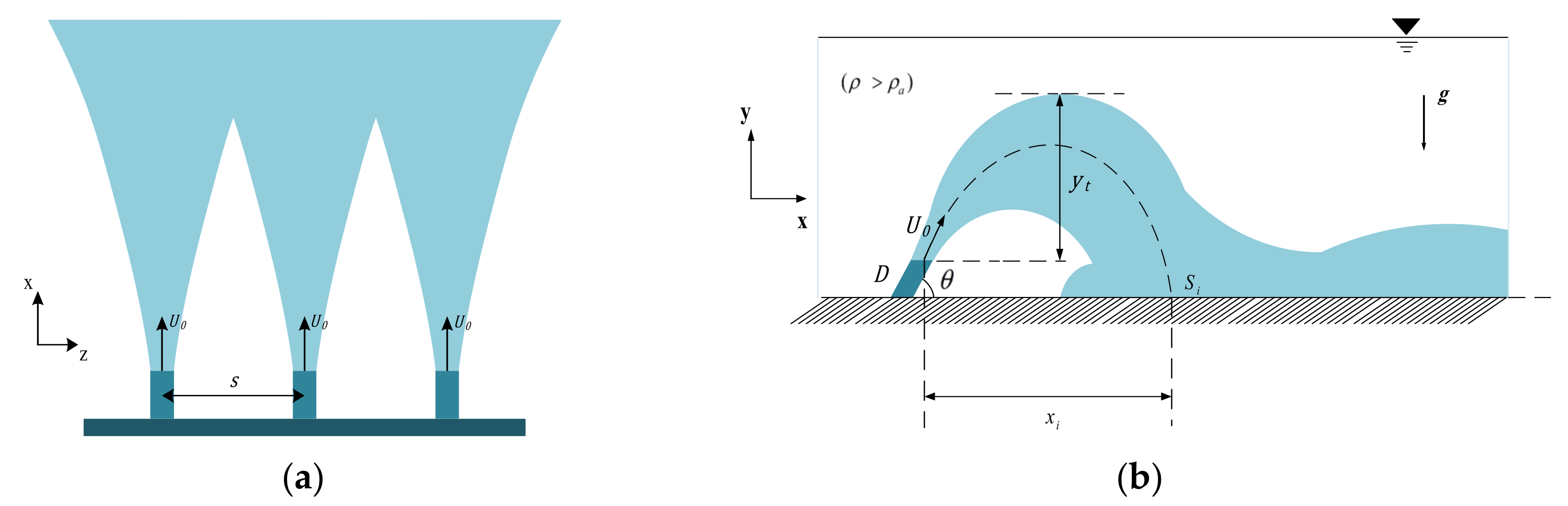
2.1. Analysis
2.2. Governing Equations
2.3. Flow and Mesh Configurations
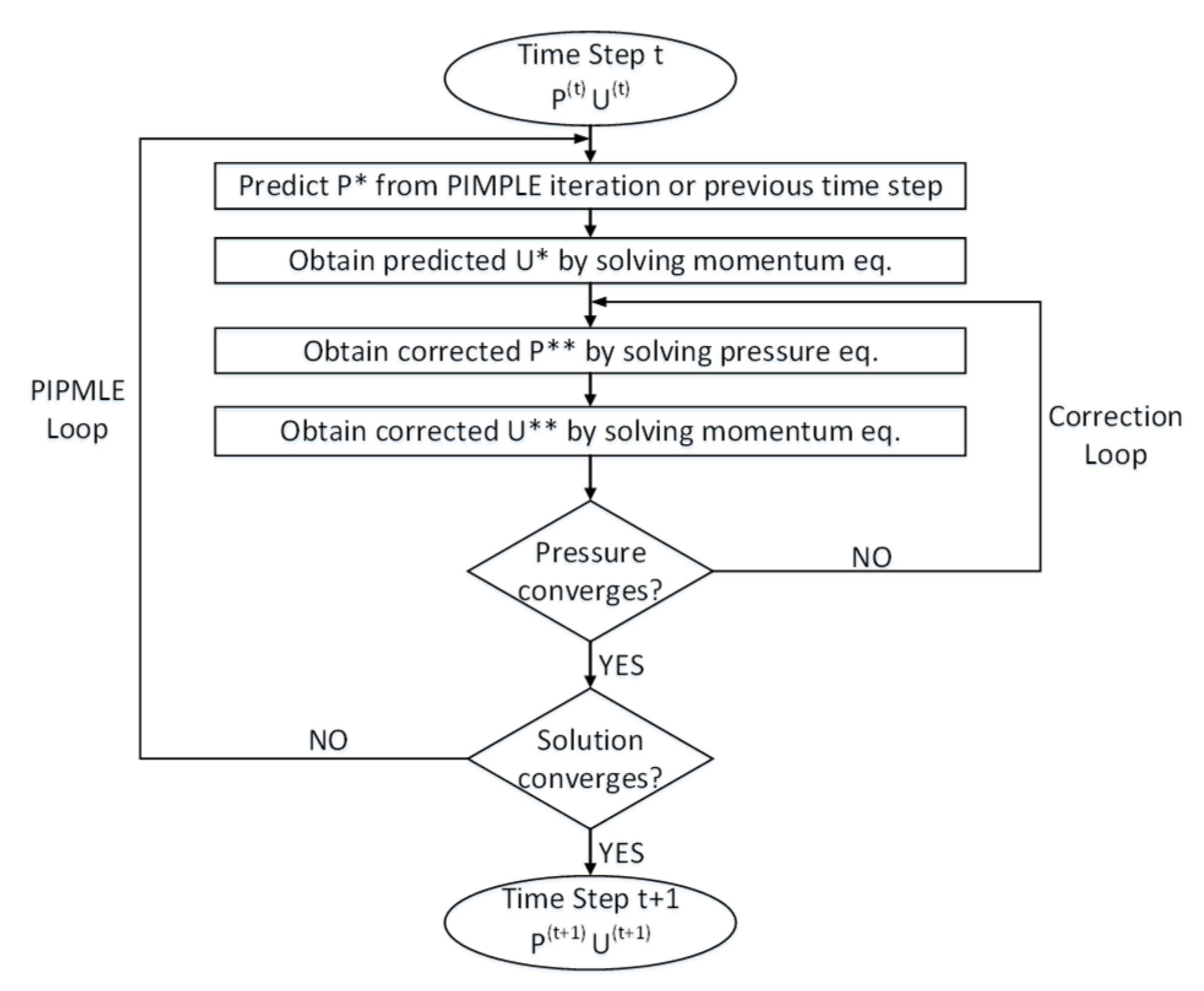
2.4. Model Setup and Numerical Algorithms
3. Results and Discussion
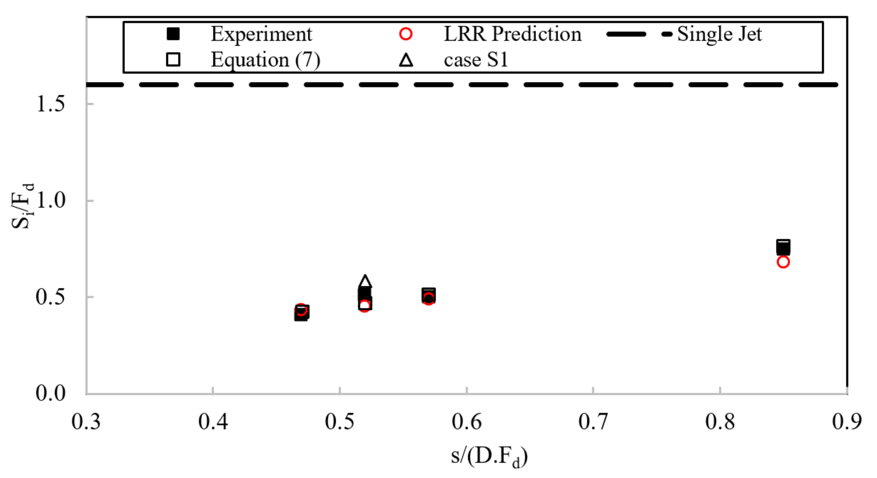
3.1. Model Validation
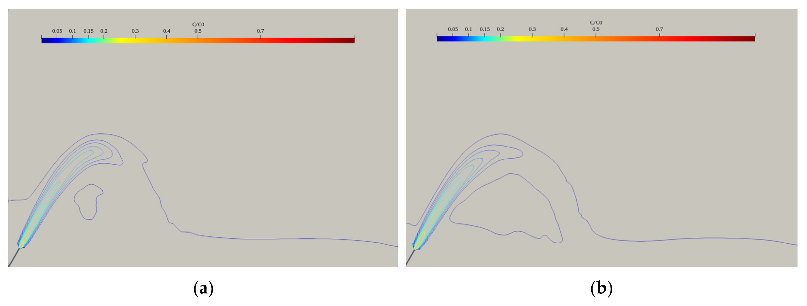
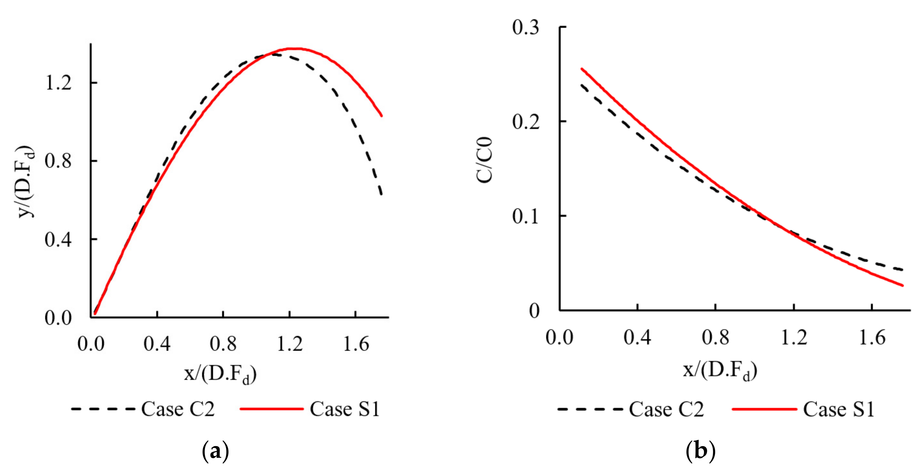
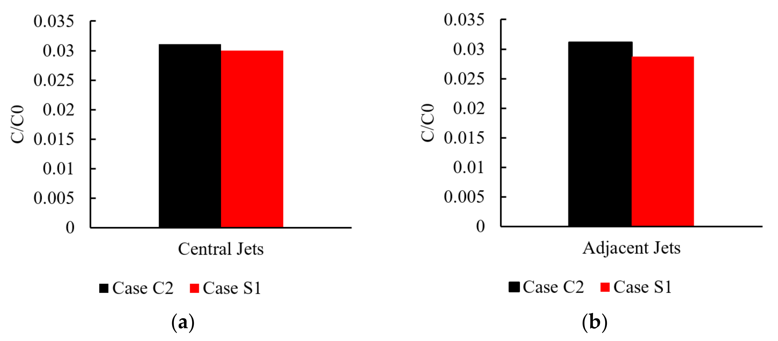
3.2. Effect of Non-Uniform Port Orientation on Jet Merging Process
4. Conclusions
Author Contributions
Funding
Institutional Review Board Statement
Informed Consent Statement
Data Availability Statement
Conflicts of Interest
References
- Einav, R.; Lokiec, F. Environmental aspects of a desalination plant in Ashkelon. Desalination 2003, 156, 79–85. [Google Scholar] [CrossRef]
- Lai, C.; Zhao, B.; Law, A.W.K.; Adams, E.E. A numerical and analytical study of the effect of aspect ratio on the behavior of a round thermal. Environ. Fluid Mech. 2015, 15, 85–108. [Google Scholar] [CrossRef] [Green Version]
- Yan, X.; Mohammadian, A. Numerical Modeling of Multiple Inclined Dense Jets Discharged from Moderately Spaced Ports. Water 2019, 11, 2077. [Google Scholar] [CrossRef] [Green Version]
- Lyu, S.; Seo, I.W.; Kim, Y.D. Experimental investigation on behavior of multiple vertical buoyant jets discharged into a stagnant ambient. KSCE J. Civ. Eng. 2013, 17, 1820–1829. [Google Scholar] [CrossRef]
- Wang, H.J.; Davidson, M.J. Jet Interaction in a Still Ambient Fluid. J. Hydraul. Eng. 2003, 129, 349–357. [Google Scholar] [CrossRef] [Green Version]
- Knystautas, R. The Turbulent Jet from a Series of Holes in Line. Aeronaut. Q. 1964, 15, 1–28. [Google Scholar] [CrossRef] [Green Version]
- Liseth, P. Mixing of merging buoyant jets from a manifold in stagnant receiving water of uniform density. In Advances in Water Pollution Research, Proceedings of the Sixth International Conference, Munich, Germany, 1 January 1973; Pergamon Press: Oxford, UK, 1973; pp. 921–936. [Google Scholar]
- Seo, I.W.; Yeo, H.K. Near-field dilution of rosette type multiport wastewater diffusers. Water Eng. Res. Int. J. Kings Waste Recycl. Auth. 2002, 3, 93–111. [Google Scholar]
- Tian, X.; Roberts, P.J.W.; Daviero, G.J. Marine wastewater discharges from multiport diffusers. I: Unstratified stationary water. J. Hydraul. Eng. 2004, 130, 1137–1146. [Google Scholar] [CrossRef]
- Tian, X.; Roberts, P.J.W. Experiments on Marine Wastewater Diffusers with Multiport Rosettes. J. Hydraul. Eng. 2011, 137, 1148–1159. [Google Scholar] [CrossRef]
- Roberts, P.J.W.; Hunt, C.D.; Mickelson, M.J.; Tian, X. Field and Model Studies of the Boston Outfall. J. Hydraul. Eng. 2011, 137, 1415–1425. [Google Scholar] [CrossRef]
- Yannopoulos, P.C.; Noutsopoulos, G.C. Interaction of vertical round turbulent buoyant jets—Part I: Entrainment restriction approach. J. Hydraul. Res. 2006, 44, 218–232. [Google Scholar] [CrossRef]
- Koh, R.C.Y.; Fan, L.N. Mathematical models for the prediction of temperature distributions resulting from the discharge of heated water in large bodies of water. EPA Water Pollut. Control. Res. Ser. 1970, 16130. Available online: https://aquadocs.org/bitstream/handle/1834/25305/EPA_Koh.PDF?sequence=1&isAllowed=y (accessed on 20 April 2022).
- Hodgson, J.E.; Moawad, A.K.; Rajaratnam, N. Concentration field of multiple circular turbulent jets. J. Hydraul. Res. 1999, 37, 249–256. [Google Scholar] [CrossRef]
- Yannopoulos, P.C.; Noutsopoulos, G.C. Interaction of vertical round turbulent buoyant jets—Part II: Superposition method. J. Hydraul. Res. 2006, 44, 233–248. [Google Scholar] [CrossRef]
- Lai, A.C.H.; Lee, J.H.W. Dynamic interaction of multiple buoyant jets. J. Fluid Mech. 2012, 708, 539–575. [Google Scholar] [CrossRef]
- Adams, E.E. Submerged Multiport Diffusers in Shallow Water with Current. Ph.D. Thesis, Massachusetts Institute of Technology, Cambridge, MA, USA, 1972. [Google Scholar]
- Marti, C.L.; Antenucci, J.P.; Luketina, D.; Okely, P.; Imberger, J. Near-Field Dilution Characteristics of a Negatively Buoyant Hypersaline Jet Generated by a Desalination Plant. J. Hydraul. Eng. 2011, 137, 57–65. [Google Scholar] [CrossRef] [Green Version]
- Abessi, O.; Roberts, P.J.W. Multiport Diffusers for Dense Discharges. J. Hydraul. Eng. 2014, 140, 04014032. [Google Scholar] [CrossRef]
- Abessi, O.; Roberts, P.J.W. Multiport Diffusers for Dense Discharge in Flowing Ambient Water. J. Hydraul. Eng. 2017, 143, 04017003. [Google Scholar] [CrossRef]
- Abessi, O.; Roberts, P.J.W. Rosette Diffusers for Dense Effluents in Flowing Currents. J. Hydraul. Eng. 2018, 144, 06017024. [Google Scholar] [CrossRef]
- Shrivastava, I.; Adams, E.E. Mixing of Tee Diffusers in Shallow Water with Crossflow: A New Look. J. Hydraul. Eng. 2019, 145, 04019006. [Google Scholar] [CrossRef]
- Xu, Z.; Otoo, E.; Chen, Y.; Ding, H. 2D PIV Measurement of Twin Buoyant Jets in Wavy Cross-Flow Environment. Water 2019, 11, 399. [Google Scholar] [CrossRef] [Green Version]
- Lee, J.H.W.; Cheung, V. Generalized Lagrangian Model for Buoyant Jets in Current. J. Environ. Eng. 1990, 116, 1085–1106. [Google Scholar] [CrossRef]
- Lee, J.H.W.; Chu, V.H. Turbulent Jets and Plumes: A Lagrangian Approach; Springer Science & Business Media: Berlin/Heidelberg, Germany, 2003; Volume 1. [Google Scholar]
- Jirka, G.H. Integral Model for Turbulent Buoyant Jets in Unbounded Stratified Flows. Part I: Single Round Jet. Environ. Fluid Mech. 2004, 4, 1–56. [Google Scholar] [CrossRef]
- Frick, W.E. Visual Plumes mixing zone modeling software. Environ. Model. Softw. 2004, 19, 645–654. [Google Scholar] [CrossRef] [Green Version]
- Taherian, M.; Mohammadian, A. Buoyant Jets in Cross-Flows: Review, Developments, and Applications. J. Mar. Sci. Eng. 2021, 9, 61. [Google Scholar] [CrossRef]
- Baum, M.J.; Gibbes, B. Field-Scale Numerical Modeling of a Dense Multiport Diffuser Outfall in Crossflow. J. Hydraul. Eng. 2020, 146, 05019006. [Google Scholar] [CrossRef]
- Roberts, P.J.W. Near Field Flow Dynamics of Concentrate Discharges and Diffuser Design. Subser. Environ. Sci. 2015, 149, 369–396. [Google Scholar] [CrossRef]
- Palomar, P.; Lara, J.; Losada, I. Near field brine discharge modeling part 2: Validation of commercial tools. Desalination 2012, 290, 28–42. [Google Scholar] [CrossRef]
- Taherian, M.; Saeidi Hossein, S.A.R.; Mohammadian, A. Overview of outfall discharge modeling with a focus on turbulence modeling approaches. In Advances in Fluid Mechanics: Modeling and Simulation; Springer: Singapore, 2022; ISSN 2364-6748. [Google Scholar]
- Ardalan, H.; Vafaei, F. CFD and Experimental Study of 45° Inclined Thermal-Saline Reversible Buoyant Jets in Stationary Ambient. Environ. Process. 2019, 6, 219–239. [Google Scholar] [CrossRef]
- Gildeh, H.K.; Mohammadian, A.; Nistor, I.; Qiblawey, H. Numerical Modeling of Turbulent Buoyant Wall Jets in Stationary Ambient Water. J. Hydraul. Eng. 2014, 140, 04014012. [Google Scholar] [CrossRef] [Green Version]
- Gildeh, H.K.; Mohammadian, A.; Nistor, I.; Qiblawey, H. Numerical modeling of 30° and 45° inclined dense turbulent jets in stationary ambient. Environ. Fluid Mech. 2014, 15, 537–562. [Google Scholar] [CrossRef]
- Gildeh, H.K.; Mohammadian, A.; Nistor, I.; Qiblawey, H.; Yan, X. CFD modeling and analysis of the behavior of 30° and 45° inclined dense jets—New numerical insight. J. Appl. Water Eng. Res. 2016, 4, 112–127. [Google Scholar] [CrossRef]
- Huai, W.-X.; Li, Z.-W.; Qian, Z.; Zeng, Y.-H.; Han, J.; Peng, W.-Q. Numerical Simulation of Horizontal Buoyant Wall Jet. J. Hydrodyn. 2010, 22, 58–65. [Google Scholar] [CrossRef]
- Oliver, C.J.; Davidson, M.J.; Nokes, R.I. k-ε Predictions of the initial mixing of desalination discharges. Environ. Fluid Mech. 2008, 8, 617–625. [Google Scholar] [CrossRef]
- Zhang, S.; Jiang, B.; Law, A.W.-K.; Zhao, B. Large eddy simulations of 45° inclined dense jets. Environ. Fluid Mech. 2015, 16, 101–121. [Google Scholar] [CrossRef]
- Zhang, S.; Law, W.K.A.; Jiang, M. Large eddy simulations of 45° and 60° inclined dense jets with bottom impact. J. Hydro-environ. Res. 2017, 15, 54–66. [Google Scholar] [CrossRef]
- Jiang, M.; Law, A.W.-K.; Lai, A.C.H. Turbulence characteristics of 45° inclined dense jets. Environ. Fluid Mech. 2018, 19, 27–54. [Google Scholar] [CrossRef]
- Xue, W.; Huai, W.-X.; Qian, Z.; Yang, Z.; Zeng, Y. Numerical simulation of initial mixing of marine wastewater discharge from multiport diffusers. Eng. Comput. 2014, 31, 1379–1400. [Google Scholar] [CrossRef]
- Tang, H.S.; Paik, J.; Sotiropoulos, F.; Khangaonkar, T. Three-Dimensional Numerical Modeling of Initial Mixing of Thermal Discharges at Real-Life Configurations. J. Hydraul. Eng. 2008, 134, 1210–1224. [Google Scholar] [CrossRef] [Green Version]
- Yan, X.; Ghodoosipour, B.; Mohammadian, A. Three-Dimensional Numerical Study of Multiple Vertical Buoyant Jets in Stationary Ambient Water. J. Hydraul. Eng. 2020, 146, 04020049. [Google Scholar] [CrossRef]
- Fischer, H.B.; List, E.J.; Koh, R.C.Y.; Imberger, J.; Brooks, N.H. Mixing in Inland and Coastal Waters; Academic Press: Amsterdam, The Netherlands, 1979. [Google Scholar]
- Roberts, P.J.W.; Ferrier, A.; Daviero, G. Mixing in Inclined Dense Jets. J. Hydraul. Eng. 1997, 123, 693–699. [Google Scholar] [CrossRef]
- Missimer, T.M.; Jones, B.; Maliva, R.G. Intakes and Outfalls for Seawater Reverse-Osmosis Desalination Facilities: Innovations and Environmental Impacts; Springer: New York, NY, USA, 2015. [Google Scholar]
- Kikkert, G.A.; Davidson, M.J.; Nokes, R.I. Inclined Negatively Buoyant Discharges. J. Hydraul. Eng. 2007, 133, 545–554. [Google Scholar] [CrossRef]
- Zeitoun, M.; McIlhenny, W. Conceptual Designs of Outfall Systems for Desalination Plants. In Offshore Technology Conference; OnePetro: Washington, DC, USA, 1970. [Google Scholar]
- Zeitoun, M.A.; McHilhenny, W.F. Model Studies of Outfall Systems for Desalination Plants; Part III. Numerical Simulation and Design Considerations; Dow Chemical Co.: Freeport, TX, USA, 1972; Available online: https://www.tib.eu/de/suchen/id/ntis:sid~oai:ds2:ntis/5319e8d74fe2d5c13d04dc1c/Model-Studies-of-Outfall-Systems-for-Desalination?tx_tibsearch_search%5Bsearchspace%5D=tn&cHash=7fcf481ee07b3258c85f7bc313ad0c16 (accessed on 20 April 2022).
- Abessi, O.; Roberts, P.J.W. Effect of Nozzle Orientation on Dense Jets in Stagnant Environments. J. Hydraul. Eng. 2015, 141, 06015009. [Google Scholar] [CrossRef]
- Lim, A.; Lam, Y. Numerical Investigation of Nanostructure Orientation on Electroosmotic Flow. Micromachines 2020, 11, 971. [Google Scholar] [CrossRef] [PubMed]
- Lim, A.E.; Lam, Y.C. Vertical Squeezing Route Taylor Flow with Angled Microchannel Junctions. Ind. Eng. Chem. Res. 2021, 60, 14307–14317. [Google Scholar] [CrossRef]
- Roberts, P.J.W.; Toms, G. Inclined Dense Jets in Flowing Current. J. Hydraul. Eng. 1987, 113, 323–340. [Google Scholar] [CrossRef]
- Versteeg, H.K.; Malalasekera, W. An Introduction to Computational Fluid Dynamics: The Finite Volume Method, 2nd ed; Pearson Education: London, UK, 2007. [Google Scholar]
- Peyret, R.; Krause, E. (Eds.) Advanced Turbulent Flow Computations; Springer: Wien, Austria, 2000. [Google Scholar]
- Hanjalic, K. Closure Models for Incompressible Turbulent Flows; Lecture Notes at Von Kármán Institute: Brussels, Belgium, 2004; p. 75. [Google Scholar]
- Abessi, O.; Saeedi, M.; Davidson, M.; Zaker, N.H. Flow Classification of Negatively Buoyant Surface Discharge in an Ambient Current. J. Coast. Res. 2012, 278, 148–155. [Google Scholar] [CrossRef]
- Lai, C.C.; Lee, J.H. Mixing of inclined dense jets in stationary ambient. J. Hydro Environ. Res. 2012, 6, 9–28. [Google Scholar] [CrossRef]
- Roberts, P.J.W.; Toms, G. Ocean outfall system for dense and buoyant effluents. J. Environ. Eng. 1988, 114, 1175–1191. [Google Scholar]
- Holzmann, T. Mathematics, Numerics, Derivations and OpenFOAM®; Holzmann CFD: Loeben, Germany, 2016. [Google Scholar]
- Killingstad, P.E. A Study of Dead Water Resistance Reynolds Averaged Navier Stokes Simulations of a Barge Moving in Stratified Waters. Master’s Thesis, University of Oslo, Oslo, Norway, 2018. Available online: https://www.duo.uio.no/bitstream/handle/10852/63458/Peter_Killingstad_masterThesis.pdf?sequence=1&isAllowed=y (accessed on 20 April 2022).
- Launder, B.E.; Reece, G.J.; Rodi, W. Progress in the development of a Reynolds-stress turbulence closure. J. Fluid Mech. 1975, 68, 537–566. [Google Scholar] [CrossRef] [Green Version]
- Lauria, A.; Alfonsi, G.; Tafarojnoruz, A. Flow Pressure Behavior Downstream of Ski Jumps. Fluids 2020, 5, 168. [Google Scholar] [CrossRef]
- Tafarojnoruz, A.; Lauria, A. Large eddy simulation of the turbulent flow field around a submerged pile within a scour hole under current condition. Coast. Eng. J. 2020, 62, 489–503. [Google Scholar] [CrossRef]
- Calomino, F.; Alfonsi, G.; Gaudio, R.; D’Ippolito, A.; Lauria, A.; Tafarojnoruz, A.; Artese, S. Experimental and numerical study of free-surface flows in a corrugated pipe. Water 2018, 10, 638. [Google Scholar] [CrossRef] [Green Version]
- Palomar, P.; Lara, J.; Losada, I.; Rodrigo, M.; Alvárez, A. Near field brine discharge modelling part 1: Analysis of commercial tools. Desalination 2012, 290, 14–27. [Google Scholar] [CrossRef]
- Yan, X.; Mohammadian, A. Numerical Modeling of Vertical Buoyant Jets Subjected to Lateral Confinement. J. Hydraul. Eng. 2017, 143, 04017016. [Google Scholar] [CrossRef] [Green Version]
- Yan, X.; Mohammadian, A.; Chen, X. Three-Dimensional Numerical Simulations of Buoyant Jets Discharged from a Rosette-Type Multiport Diffuser. J. Mar. Sci. Eng. 2019, 7, 409. [Google Scholar] [CrossRef] [Green Version]
- OpenFOAM. The OpenFOAM Foundation; OpenCFD Ltd.: Bracknell, UK, 2015. [Google Scholar]
- Li, Y.; Geng, X.; Wang, H.; Zhuang, X.; Ouyang, J. Simulating the frontal instability of lock-exchange density currents with dissipative particle dynamics. Mod. Phys. Lett. B 2016, 30, 1650200. [Google Scholar] [CrossRef]
- Shao, D.; Adrian, W.K.L. Mixing and boundary interactions of 30 and 45 inclined dense jets. Environ. Fluid Mech. 2010, 10, 521–553. [Google Scholar] [CrossRef]
- Roberts, P.J.W.; Snyder, W.H.; Baumgartner, D.J. Ocean Outfalls. III: Effect of Diffuser Design on Submerged Wastefield. J. Hydraul. Eng. 1989, 115, 49–70. [Google Scholar] [CrossRef]


| Case | Diameters (mm) | Effluent Density (kg/m3) | Ambient Density (kg/m3) | Velocity (m/s) | |||
|---|---|---|---|---|---|---|---|
| C1 | 1.93 | 1013.8 | 999.8 | 1.03 | 63.1 | 0.47 | 60-60-60 |
| C2 | 1.93 | 1013.8 | 999.8 | 0.92 | 56.8 | 0.52 | 60-60-60 |
| C3 | 1.93 | 1013.8 | 999.8 | 0.85 | 52 | 0.57 | 60-60-60 |
| C4 | 1.93 | 1013.8 | 999.8 | 0.57 | 34.7 | 0.85 | 60-60-60 |
| S1 | 1.93 | 1013.8 | 999.8 | 0.92 | 56.8 | 0.52 | 45-60-45 |
| [3] | Current Study | |
|---|---|---|
| Boundary conditions | ||
| Bottom wall | Slip * | No-slip |
| Symmetry planes | Symmetric | Symmetric |
| Inlets | Fixed velocity inlet | Fixed velocity inlet |
| Atmosphere | Inlet–outlet | Pressure–inlet outlet |
| Outlet | Inlet–outlet | Pressure–inlet outlet |
| Number of cells | 113,400 | 528,000 |
| Software | OpenFOAM | OpenFOAM |
| Solver | twoLiquidMixingFoam | twoLiquidMixingFoam |
| Discretization schemes | ||
| Temporal term | Euler | Euler |
| Gradient term | Linear | Linear |
| Laplacian term | Linear | Linear |
| Divergence term | Linear, vanLeer, and upwind | Linear, vanLeer, and upwind |
Publisher’s Note: MDPI stays neutral with regard to jurisdictional claims in published maps and institutional affiliations. |
© 2022 by the authors. Licensee MDPI, Basel, Switzerland. This article is an open access article distributed under the terms and conditions of the Creative Commons Attribution (CC BY) license (https://creativecommons.org/licenses/by/4.0/).
Share and Cite
Saeidi Hosseini, S.A.R.; Mohammadian, A.; Roberts, P.J.W.; Abessi, O. Numerical Study on the Effect of Port Orientation on Multiple Inclined Dense Jets. J. Mar. Sci. Eng. 2022, 10, 590. https://doi.org/10.3390/jmse10050590
Saeidi Hosseini SAR, Mohammadian A, Roberts PJW, Abessi O. Numerical Study on the Effect of Port Orientation on Multiple Inclined Dense Jets. Journal of Marine Science and Engineering. 2022; 10(5):590. https://doi.org/10.3390/jmse10050590
Chicago/Turabian StyleSaeidi Hosseini, Seyed Ahmad Reza, Abdolmajid Mohammadian, Philip J. W. Roberts, and Ozeair Abessi. 2022. "Numerical Study on the Effect of Port Orientation on Multiple Inclined Dense Jets" Journal of Marine Science and Engineering 10, no. 5: 590. https://doi.org/10.3390/jmse10050590