
Longitudinal Vibration of Marine Propulsion Shafting: Experiments and Analysis

1
School of Naval Architecture and Ocean Engineering, Huazhong University of Sciences and Technology, Wuhan 430074, China
2
Hubei Key Laboratory of Naval Architecture and Ocean Engineering Hydrodynamics (HUST), Wuhan 430074, China
*
Author to whom correspondence should be addressed.
J. Mar. Sci. Eng. 2022, 10(9), 1173; https://doi.org/10.3390/jmse10091173
Submission received: 18 July 2022
/
Revised: 18 August 2022
/
Accepted: 19 August 2022
/
Published: 23 August 2022
(This article belongs to the Special Issue Developments in Marine Propulsors)
Abstract
:The longitudinal vibration of the propulsion shaft system is a challenging issue for marine noise management. We conducted various static and dynamic tests on our built test rig for the shafting system, presenting the results in this paper. By combining experimental data and the particle swarm optimization algorithm, we identified the structural parameters that are difficult to obtain. With these parameters we establish a completed theoretical model of a shaft system containing branches, analyze how and why static thrust affects vibration, and give quantitative results of the force transmissibility. Our work provides a reference for subsequent researchers.
1. Introduction
Longitudinal vibration of the marine propulsion shafting system, which is under non-constant thrust excitation, arises with propeller propulsion technology, because the propeller operates in a stern flow field that is nonuniform in time and space. This nonuniformity derives from the asymmetry of the hull [1]. In space, the nonuniformity generates a pulsating thrust of the blade and multi-blade frequency related to the propeller rotational speed, with continuous broadband excitation in time. With propellers still being the dominant propulsion technology, such longitudinal vibration problems are bound to exist. For marine vehicles, the longitudinal vibration of the propeller-shafting system is directly related to the radiated noise of the hull and becomes an essential target to improve the acoustic stealth [2].
Severe longitudinal vibration problems in propulsion shafting systems first occurred in surface ships in the 1950s [3]. The thin, hollow drive of the shaft makes it less rigid, causing the first-order critical rotational speed to fall within the shaft’s operating range, and the multiple propeller shafting system can mutually aggravate the stern flow distribution, increasing the excitation force. In the case of underwater vehicles, the complex conditions at different depths and seawater densities result in variations of the propeller thrust, making longitudinal vibration more troublesome and uncertain.
The key to clarifying the longitudinal vibration characteristics is to develop a suitable model of the shafting system. In tests on the longitudinal vibration of the shafting system of USS Simon Lake, Gary found that the gearbox, turbine, and compressor could be considered as a whole [4]. Couchman simplified the shafting system to a single-degree-of-freedom system model, and proposed the calculation of equivalent mass and equivalent stiffness based on testing the first-order natural frequency of a Type V ship [5]. Kelzon considered the shafting system as a continuous system, and simplified it as a uniform shaft model, with the propeller and thrust bearing as a concentrated mass and elastic boundary condition, respectively [6]. Murawski found that there were torsional–longitudinal and bending–longitudinal coupled vibrations in the diesel engine shafting system. He emphasized the significance of boundary conditions, especially the accurate modeling of the thrust bearing [7].
The above studies generally equated the propulsion shafting system with a non-rotating rod, not a rotor. A rotating shafting system has a lubricating oil film with the stiffness and damping properties [8]. The wedge-shaped lubricating oil film between the thrust ring and thrust block in the thrust bearing affects the longitudinal vibration. By introducing the lubricant film into the shafting model, a relationship between shaft rotational speed and longitudinal vibration characteristics can be established.
The complexity and difficulty of longitudinal vibration problems in shafting systems arise from non-linear factors such as bearing lubrication, friction, and assembly clearances. The accuracy of the calculation depends on the refinement of the model and the reliabilities of the dynamic parameters. A more effective approach is to combine theory and experimentation. Table 1 summarizes and compares the shafting system test rigs in the literature, which differ in composition and function according to the focus of the study. Pan [9] and Wang [10] utilized propellers in their shafting test rig. When the propeller speed was high, the water flow could not return in time and propeller idling occurred, resulting in unstable results. The effects of static thrust and rotational speed on the shafting system can be tested separately under the condition of a power source, but no corresponding tests were shown in [11,12]. In terms of the thrust bearing structure, Zhao innovatively utilized a hydraulic piston as the thrust block support structure, as opposed to the traditional balance block. This paper shows our second type of shafting system test rig.
This paper investigates the longitudinal vibration characteristics of the shafting system by combining experimental methods and theoretical analysis to ensure reliability and validity. We performed longitudinal vibration tests on our test rig with different combinations of static thrust and rotational speed. The accurate structural stiffness of the shafting system of our test rig was also tested. We model the shafting system of the test rig by the transfer matrix method, considering the static thrust device. The acceleration frequency response function of the thrust bearing is presented in this paper. To refine the model, we identify the remaining uncertain dynamic parameters using the Particle Swarm Optimization Algorithm. We aim to clarify how and why static thrust and longitudinal force transfer branches affect the longitudinal vibration of the shafting system, and we aim to identify the role and contribution of the thrust bearing in this. In addition, the data presented in this paper can provide subsequent researchers with ideas, data references, and even a direct reference for rig construction.
2. Test Rig
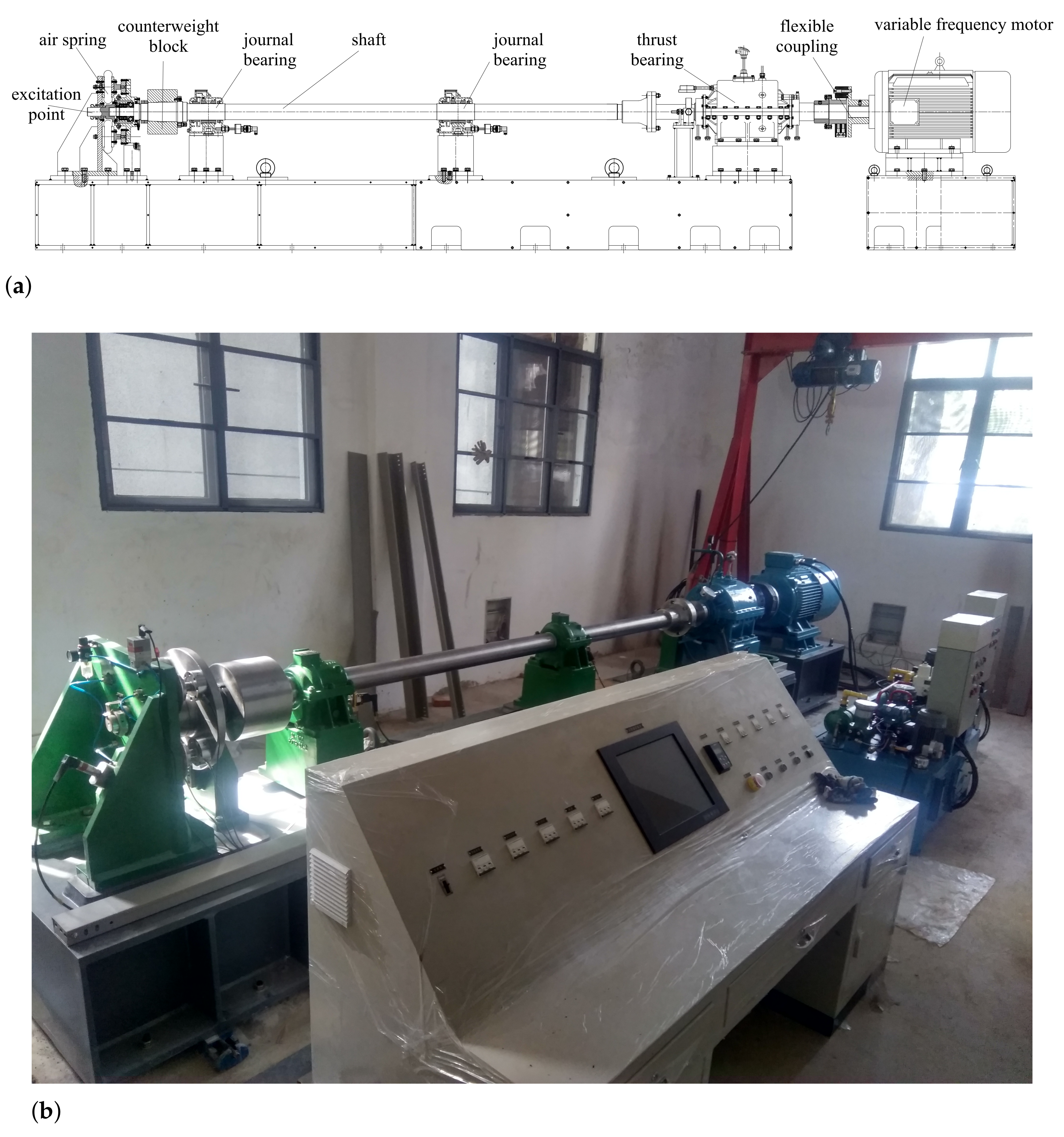
The shafting system test rig we built is shown in Figure 1 and includes the air spring static thrust device, counterweight block, journal bearings, shaft, thrust bearing, flexible coupling, variable frequency motor, etc. To further reduce the disturbing effects of high-frequency vibration of the motor, it is mounted independently on one base, while the rest of the shafting system is mounted on another. An electrical console is designed, as well as a hydraulic lubrication system and an air system. The main technical parameters are:
- A total length of shaft 5000 mm;
- A basic diameter 105 mm;
- A counterweight block mass 89.6 kg;
- A maximum static thrust 55 kN.
The test rig simulates propeller propulsion using parallel static and dynamic forces. The air spring mounted on the stern provides static thrust, and its value can be adjusted by changing the airbag pressure. Dynamic forces were excited by force hammers, which also act on the stern end to simulate propeller excitation forces. To achieve the simultaneous transfer of static and dynamic forces to the rotating shaft, we designed a tapered ball bearing between the shaft and the air spring device to solve the connection problem between the rotating and the non-rotating shaft. Compared to using a propeller, the parallelism of static and dynamic forces allows the static thrust and rotational speed to be changed independently for the vibration test.
3. Vibration Tests on the Rig
3.1. Longitudinal Vibration Characteristics of Shafting
At the stern end, we use an excitation force hammer to apply an impulse excitation in the axial direction and arrange acceleration sensors on the thrust bearing housing and base to test the acceleration response. As the thrust bearing is the main transmission path for the longitudinal vibration of the shafting system, its acceleration response can reflect the amplitude of the secondary excitation force, which would be applied to the hull in practice.
Specifically, two acceleration sensors are arranged along the axis at the top of the upper housing of the thrust bearing, and the other two are arranged at the base of the thrust bearing, both symmetrically along the axis. The longitudinal vibration in the frequency range of 300 Hz is of interest. The sampling frequency is 1280 Hz, and the frequency resolution is 0.625 Hz. The acceleration frequency response of the thrust bearing was collected under different combinations of static thrusts and shaft rotational speeds.
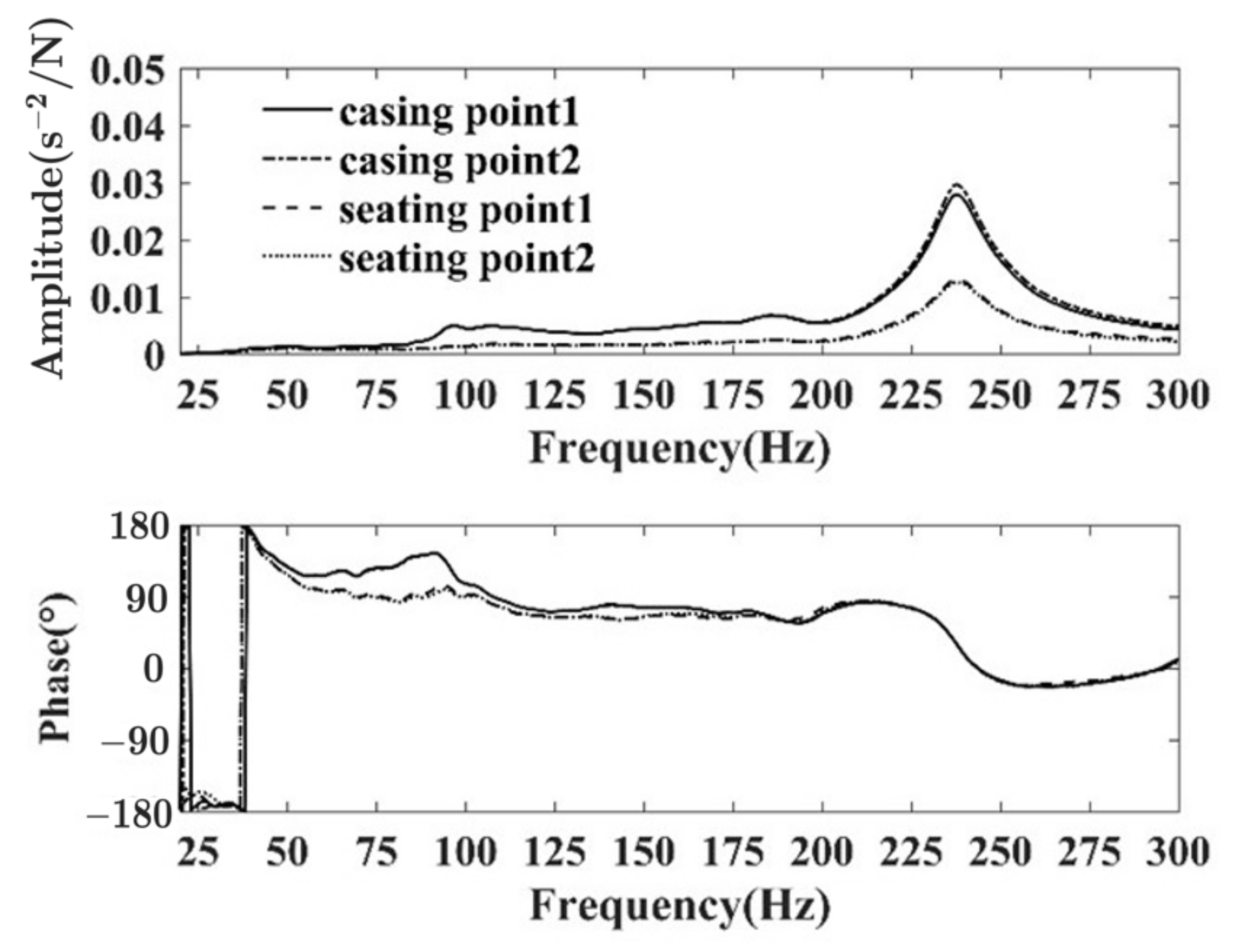
Figure 2 shows the acceleration frequency response curve of the thrust bearing tested at a static thrust of 30 kN and a shaft speed of 60 rpm. In Figure 2, the casting points denote the two sensors at the top, and the seating points denote the two sensors at the base. It can be seen that the acceleration frequency responses of the two measurement points of the thrust bearing housing are consistent, indicating that the housing is vibrating as a whole, and a similar situation occurs in the base. The acceleration frequency response curves of the housing and base are similar, with only the peaks differing, indicating that the longitudinal vibration attenuates in the transmission channel of the thrust bearing structure. Except for those of the low frequencies, all phase angles are between 0°∼180°, indicating that only the first-order longitudinal vibration exists in the 300 Hz frequency range. Its corresponding natural frequency value is 237.5 Hz. There are several resonance peaks of lower amplitude on the housing’s acceleration frequency response curve, related to local resonances in the thrust bearing, which are discussed in Section 5.
3.2. Comparison of Different Rotational Speeds
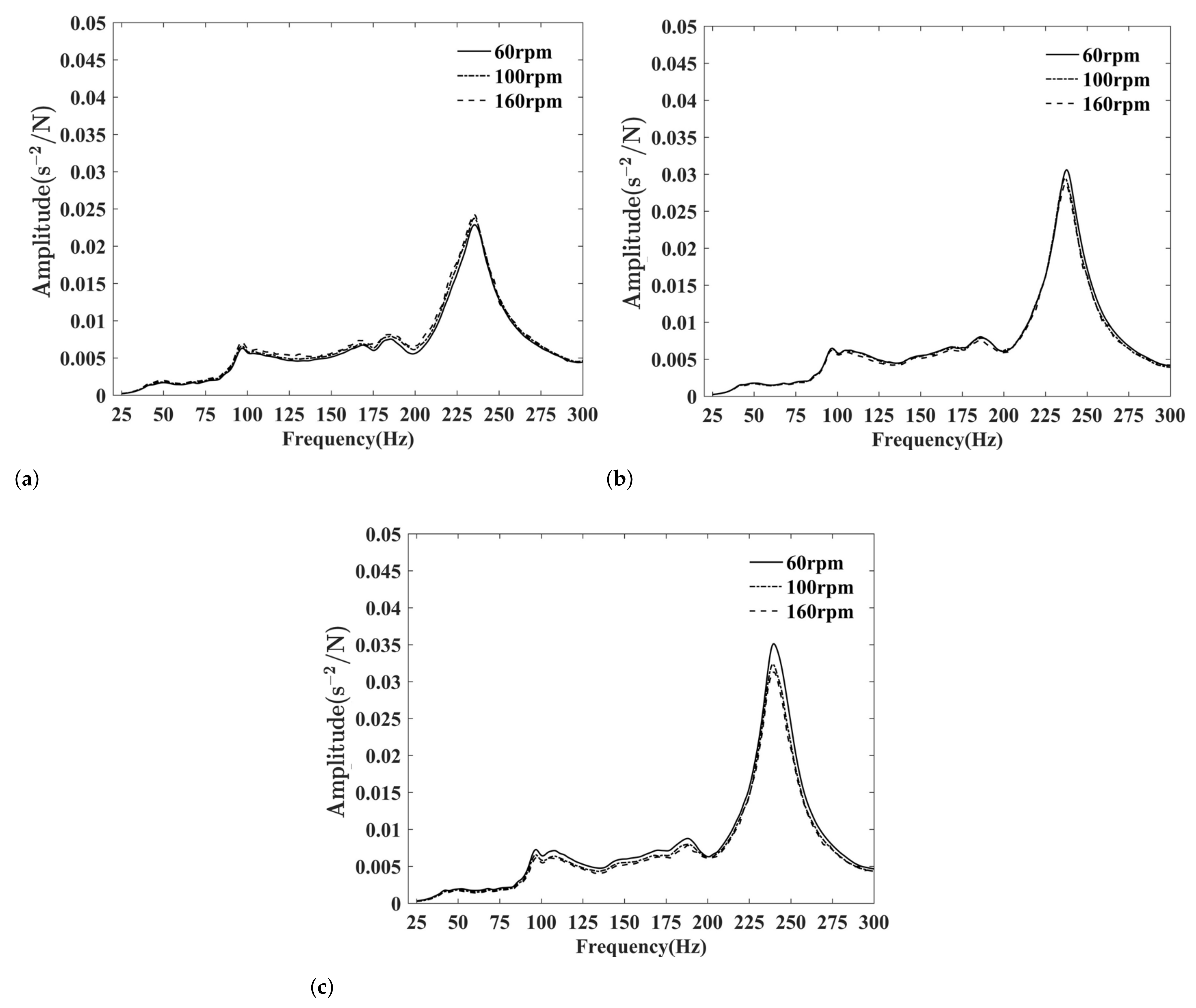
We repeated the longitudinal vibration test by varying the shaft rotational speed under the same static thrust. Without a loss of generality, the following discussion and analysis are based on the acceleration frequency responses of the base of the thrust bearing, because those of the thrust bearing housing and base are similar.
The results are shown in Figure 3, and the curves in each subfigure are under the same static thrust while at different rotational speeds. The thrust bearing acceleration frequency response curves are consistent under each thrust, especially the resonance frequency, which indicates that the shaft rotational speed is not a major factor affecting vibration.
3.3. Comparison of Different Static Thrusts
We repeated the longitudinal vibration test by varying the static thrust at the same rotational speed. The results are shown in Figure 4, including those when the shaft did not rotate. The resonance peak changes as the static thrust increases: the resonance peak amplitude and the corresponding frequency both increase. The increase in resonance peak amplitude derives from a reduction in shafting damping, which means that the greater the static thrust, the less damp. The increase in resonance frequency derives from a change in shafting system stiffness, which may originate from the lubricating oil film between the thrust ring and the thrust block, or the air spring static thrust device.
From Figure 4d, the effect of the static thrust on the non-rotating shafting system is the same as that of the rotating one. As the thrust bearing has no lubricating oil film when the shaft is not rotating, it can be deduced that the increase in resonance frequency is related to the change in stiffness of the air spring static thrust device. Therefore, the static thrust affects the longitudinal vibration by varying the air spring stiffness. This property is similar if the test rigs use a static thrust device to simulate the propeller.
4. Test for Stiffness
Apart from the stern and thrust shafts, most of the other structures in the shafting system are assemblies and welded parts, such as thrust bearings. Therefore, it is difficult to calculate the stiffness accurately. Vassilopoulos has proposed a theoretical calculation method for thrust bearing stiffness [16], where the stiffness of each component is first calculated based on material mechanics or contact theory, and then assembled to obtain the thrust bearing stiffness. As the stiffness of each element is obtained based on a simplified model and assumptions, the result is still an approximate solution. To provide accurate stiffness values for the vibration analysis, we directly tested the stiffness of the main structures, including the air spring static thrust device, the thrust bearing, and the base.
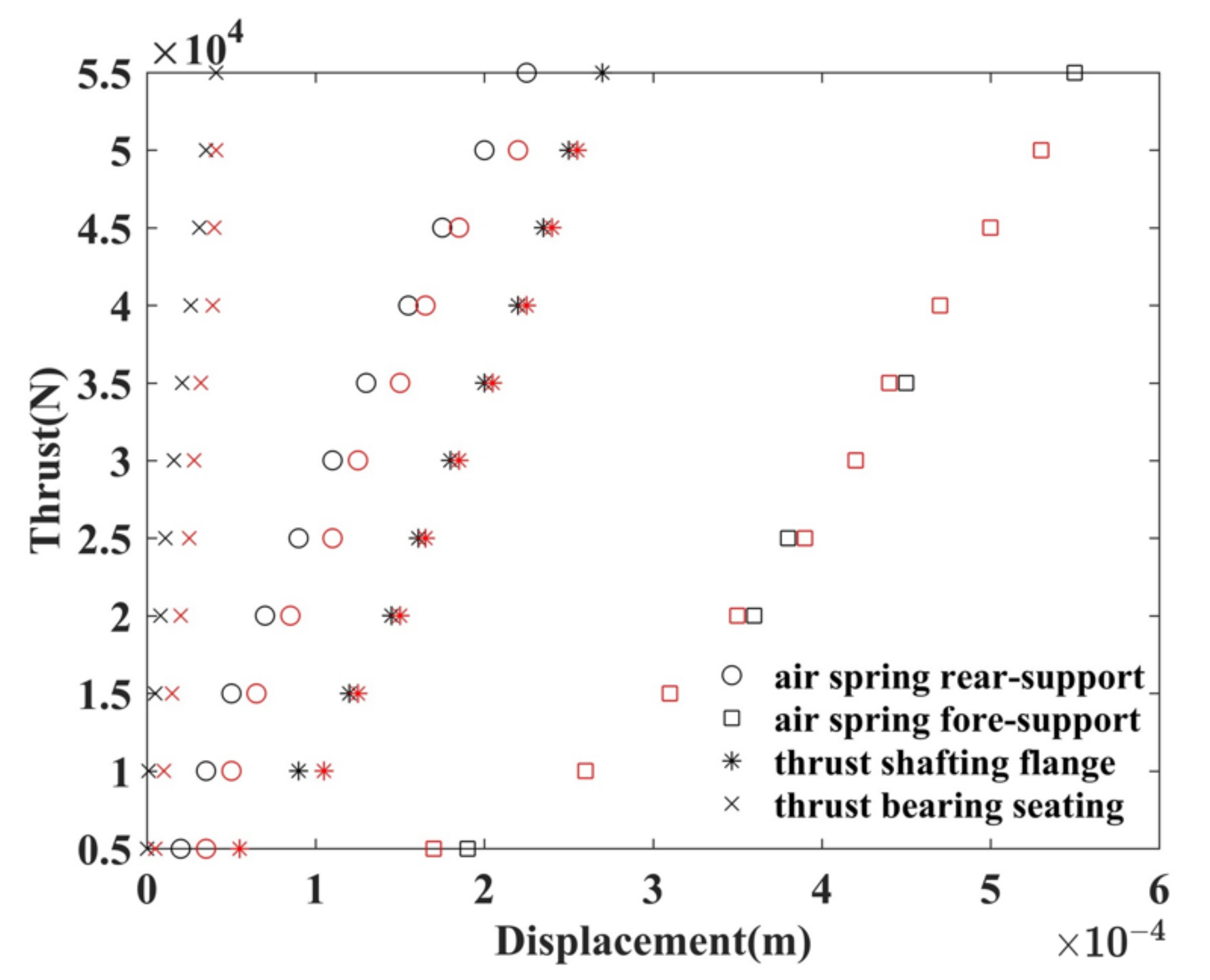
The static thrust force was applied to the stern end in certain load steps, and the displacement was measured at each step. We used 11 steps during the test. A percentage meter is located on the front and rear supports of the airbag, the thrust shaft flange, and the foot of the thrust bearing to measure the displacement values. The stiffness of the shafting system can be obtained at different speeds to analyze the variation of stiffness. To reduce random error interference, we repeated the process at the same speed to obtain an average value. We present the “static thrust-displacement” test data at 60 rpm in Figure 5, as the results at different rotational speeds are consistent. In Figure 5, the black points stand for loading and the red for unloading. It can be seen that the displacements during loading and unloading are not consistent, especially in the case of the airbag front bracket. The front bracket has a weaker stiffness than the rear and is the main direction of the airbag’s deformation.
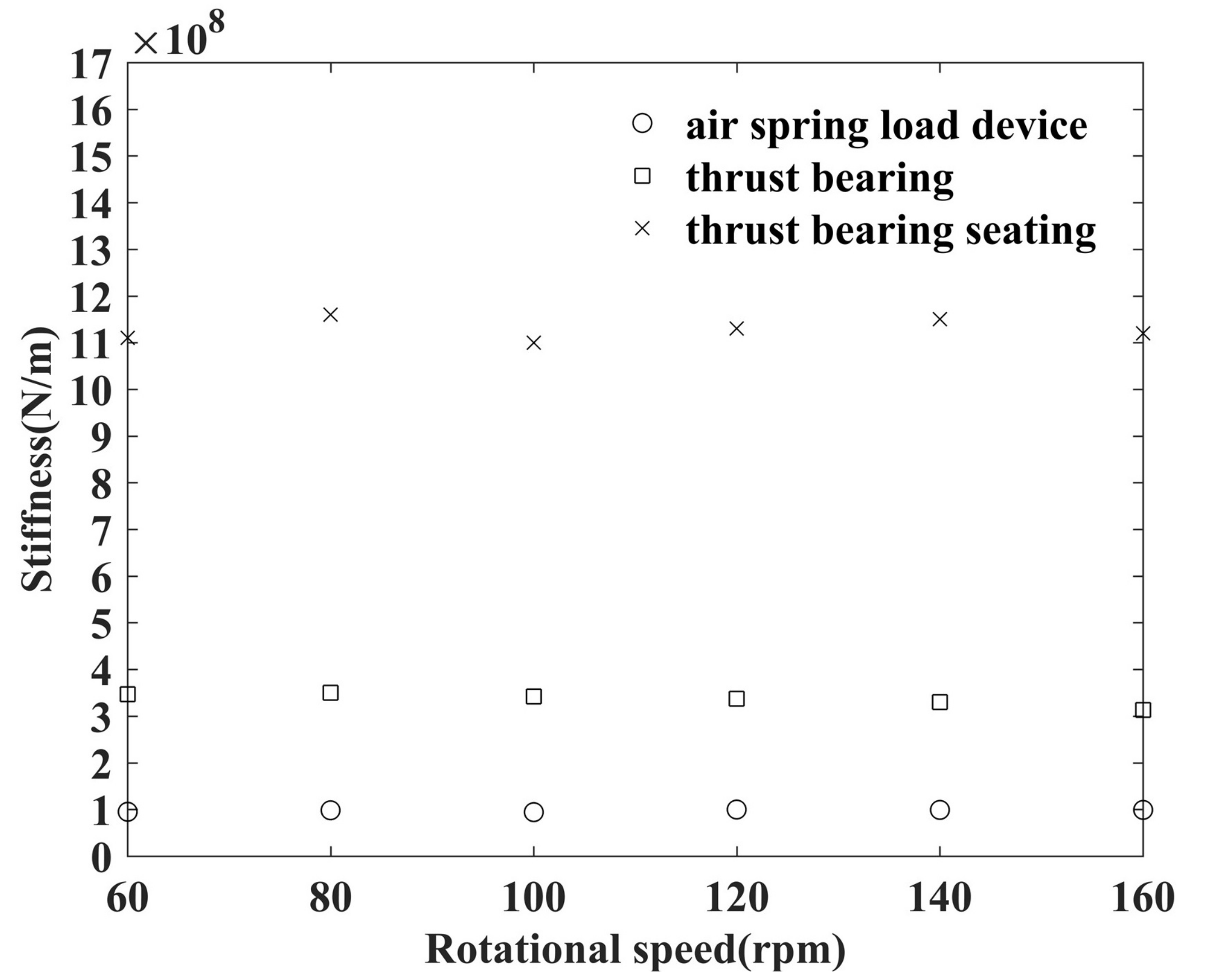
We performed least squares linear fitting on the “static thrust-displacement” data. The results at different rotational speeds are shown in Figure 6, where the slopes of the fitted lines represent the stiffness values. It can be seen that the static thrust device, thrust bearing, and base stiffness are stable at different rotational speeds, 1.0 × 10⁸ N/m, 3.4 × 10⁸ N/m, and 1.1 × 10⁹ N/m, respectively.
The least squares linear fitting process is shown as follows:
- For a certain rotational speed, save the corresponding thrusts as the components of an 11 × 1 vector x and save the corresponding displacements as the components of an 11 × 1 vector y. Recall that we used 11 different thrust forces during our test.
- Use four function bases , where and u is the independent variable of the function.
- Calculate , where .
- The normal equation can be expressed bywhere ’s are the coefficients of the fitted function , is the ith component of x, and is the ith component of y.
- Let denote the 11 × 4 matrix in (1). According to the theory of the least squares linear fitting, we have
- We obtain the fitted function of this certain rotational speed. Calculate the corresponding a’s of other rotational speeds.
- The results show that ’s at every rotational speed, stating that the stiffnesses are in the elastic range. Therefore, we save the s as the corresponding stiffnesses.
We calculate the fluctuating values of different rotational speeds, comparing with the fitted stiffness of rotational speed 60 rpm. The results are present in Table 2 and confirm our point clearly and directly, i.e., the static thrust device, thrust bearing, and base stiffness are stable at different rotational speeds. It can be seen that no fluctuating value exceeds 10%.
5. Modeling the Shafting and Identifying the Parameters
5.1. Modeling the Shafting Using the Transfer Matrix Method
The shafting system is suitable for the analysis of its longitudinal vibration, using the transfer matrix method, because of its typical chain characteristic. The model of the test rig shafting system is shown in Figure 7, from the air spring static thrust device to the flexible coupling. In Figure 7, the shaft is simplified to a series of continuous uniform shafts, and the slave end of the flexible coupling is simplified to a concentrated mass. As the static thrust and the hammer excitation are applied in parallel at the stern end, the static thrust device also transmits the longitudinal vibrations and is equivalent to a shafting branch, which is simplified as a “spring-mass” system. The thrust bearing is also a branch of the shafting and has two longitudinal transmission channels: (1) the fore shaft, which transmits vibrations to the flexible coupling, and (2) the thrust ring, which transmits vibrations to the internal structures, such as the thrust block, and the base. Certainly, (2) is primary. Therefore, as shown in Figure 7, the model includes three types of dynamic components: concentrated mass, uniform shaft, and branch.
The equation for the two ends of the air spring static thrust device can be expressed as:
where:
- denotes the square root of −1, i.e., j2 = −1;
- The superscripts l and r denote the left and right end, respectively;
- U denotes the displacement;
- F denotes the force;
- Mp denotes the concentrated mass;
- Kp denotes the stiffness;
- ηp denotes the damping ratio of the static thrust device.
For simple harmonic vibration, we deduce the thrust device transfer matrix from Equation (2) as:
Equation (3) shows that the effect of airbag stiffness is to reduce the effective reference mass of the static thrust device. From Figure 7, we have the global transfer matrix equation as:
where:
- and denote the stiffness and damping ratio, respectively, of the lubricating oil film;
- , and denote, respectively, the concentrated mass, stiffness, and damping ratio of the thrust bearing;
- , and denote, respectively, the concentrated mass, stiffness, and damping ratio of the thrust bearing base;
- In addition, we use to denote an input or output matrix, thus distinguishing it from the transfer matrix.
Under the rigid boundary condition, we have . Substitute it into Equation (4), then:
holds, where is the dynamic stiffness of the thrust bearing.
The thrust bearing forms a transmission path for longitudinal vibrations in the shafting system, as shown in Figure 8, and the fore shaft forms another one.
According to displacement continuity and force equilibrium conditions, we have:
Unite Equations (5) and (6), then:
holds. Unite Equations (6) and (7), and we have:
and the transfer matrix of the thrust bearing as:
To obtain the acceleration frequency response function of the thrust bearing, we denote the global transfer matrix equation as:
According to the assembly gap along the axis between the slave and the active end of the flexible coupling, the slave end can be regarded as being under a free boundary condition. Therefore, we have:
from Equation (8), as .
The transfer matrix from the air spring static thrust device to the thrust ring can be expressed by:
5.2. Identifying the Parameters
In the above transfer matrix model of the shafting system, the stiffness values of the static thrust device, the thrust bearing, and the base have been tested, but the reference mass is uncertain because they are assemblies and cannot simply be calculated in terms of the actual mass. In addition, the structural damping ratios are also uncertain, let alone those values of the lubricating oil film. Refs. [17,18,19] performed tests for the dynamic characteristics of the lubricating oil film, but these were all performed using indirect methods, and required the substitution of the test data into the established model.
Our strategy is to identify the above parameters (i.e., , , , , , , , and ) based on the acceleration frequency response function obtained from our test. Identification is the optimization of the parameters, and the method is the residual function optimization solution. Here, the residual function refers to the difference between the theoretical and experimental results.
The optimization problem for the dynamic parameters of the shaft system is described as:
- Optimization variable: ;
- Constraint conditions:
- kg;
- ;
- N/m;
- Ns/m;
- kg;
- ;
- kg;
- .
where the ranges of the lubricant oil film stiffness and damping are based on test data from the literature; - Objective function: , where is the acceleration frequency response function of the thrust bearing, obtained in our test.
We solve the above optimization problem using the particle swarm optimization algorithm [20], which is a population-based intelligent evolutionary computation. Using the results under a static thrust of 30 kN and at a shaft rotational speed of 60 rpm, the parameters were identified as:
- kg;
- ;
- N/m;
- Ns/m;
- kg;
- ;
- kg;
- .
Substituting these parameters into the model of the shafting system, we calculated the theoretical results as shown in Figure 9. It can be found that the theoretical and experimental acceleration frequency responses are in good agreement, confirming that the transfer matrix model can simulate the actual longitudinal vibration characteristics.
We calculated the mean errors of some certain frequency bands and presented them in Table 3. At first appearance, the errors seem large. However, the errors around the two dominant resonance frequencies are not larger than 5%. As our interest focus on the resonance frequencies and the response of the nearby frequency, we are thus optimistic about the result. Moreover, the redundant mechanism assembly components and the local damps of the test rig make it an arduous task to simulate at every frequency. Appropriate simplification is common practice. Therefore, the result is acceptable.
6. Discussion
To verify the previous inference that the stiffness of the airbag affects the resonant frequency, we varied the stiffness and calculated the corresponding acceleration frequency response of the thrust bearing, based on the identified dynamic parameters. The results are shown in Figure 10. Unlike Figure 4, the resonance peak in Figure 10 decreases as the stiffness increases, because in the theoretical calculation only the stiffness changed, while the damping ratio of the shafting structure did not. In our vibration tests, they changed simultaneously when the static thrust was adjusted.
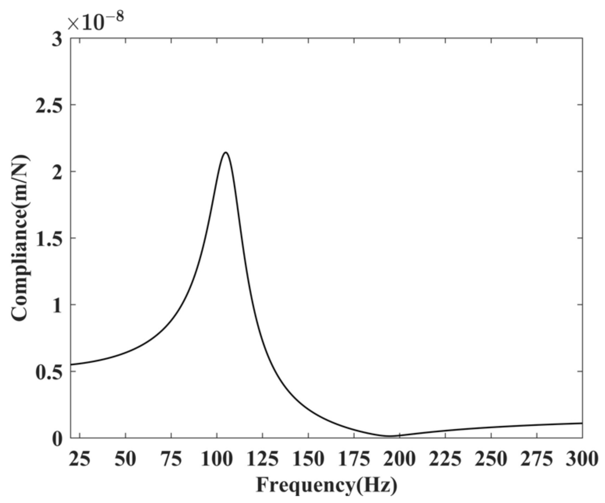
By substituting the identified parameters into Equation (5), we have the dynamic flexibility curve shown in Figure 11. The peak of the curve corresponds to the natural frequency of the thrust bearing, which is 103 Hz. According to the test results shown in Figure 2, the frequency of the first local resonance peak is 98 Hz, which is closer to the natural frequency of the thrust bearing, indicating that it is generated by the resonance of the thrust bearing. The coupling between the thrust bearing and the shafting is weak at this time.
As mentioned previously, the thrust bearing and the fore shaft are two paths of longitudinal vibrations. The primary path can be identified by comparing the excitation forces transmitted. The hammer excitation data were collected for spectral analysis and, together with the identified parameters, substituted into the shafting model. We calculated the excitation forces transferred to the thrust bearing and front thrust shaft, respectively. The results of the transmissibility are shown in Figure 12. The comparison shows that the thrust bearing is the main transmission channel for longitudinal shafting vibration. In addition, the force transmission characteristics show that the hammer excitation force is significantly amplified in the resonant state of the shafting system.
7. Conclusions
We designed a test rig to simulate the propulsion system of a ship. The rig simulates propeller propulsion in parallel with static and dynamic forces and allows the rotational speed and static thrust to be varied independently. Static and dynamic tests on the test rig were performed, and the dynamic parameters of the shafting system were identified by combining numerical models and the particle swarm optimization algorithm.
The test results and the theoretical analysis are consistent, proving the validity of both methods and the reliability of the results. Of the two variables, the longitudinal vibration is less affected by the shaft rotational speed, while the static thrust is the primary factor.
The static thrust device, as well as the thrust bearing, constitutes a branch of the shafting system, and its stiffness should be taken into account in the model. The branch effects reduce the original effective mass of the component. We obtain quantitative evidence to show that the thrust bearing is the main channel of the longitudinal vibration, and the excitation force via it is significantly amplified when the shafting resonates. As the additional transfer paths are unavoidable for any shafting system, our test data and analysis can provide a reference for subsequent researchers.
Author Contributions
Formal analysis, W.C., Y.Z. and H.Y.; investigation, W.C. and Y.Z.; methodology, W.C. and G.Z.; writing—original draft, W.C.; writing—review and editing, H.Y. All authors have read and agreed to the published version of the manuscript.
Funding
This research was funded by the National Natural Science Foundation of China under Grant No. 51479078, No. 52101354, the Talent Team Project of Zhangjiang City in 2021 and the R & D and industrialization project of the offshore aquaculture cage nets system of Guangdong Province of China (grant No.2021E05034). Huazhong University of Science and Technology funds the APC.
Institutional Review Board Statement
Not applicable.
Informed Consent Statement
Not applicable.
Data Availability Statement
Not applicable.
Acknowledgments
The authors would like to thank the editors and reviewers for their constructive comments, which will improve the manuscript.
Conflicts of Interest
The authors declare no conflict of interest.
References
- Tang, W.L.; Yu, M.S.; Wang, B. Hydrodynamic Noise Theory; Science Press: Beijing, China, 2020. [Google Scholar]
- Wu, C.; Lei, Z.; Xu, X.; Wang, Q.; Wang, C. An analysis of low-frequency propeller vibration and sound radiation characteristics: The Jellyfish effect. Chin. J. Ship Res. 2020, 15, 154–160. [Google Scholar]
- Goodwin, A. The design of a resonance changer to overcome excessive axial vibration of propeller shafting. Trans. Inst. Mar. Eng. 1960, 72, 37–63. [Google Scholar]
- Antonides, G.P. Longitudinal Vibration of Propulsion System on USS Simon Lake (AS-33); Technical Report; David Taylor Model Basin: Washington, DC, USA, 1966. [Google Scholar]
- Couchman, A. Axial Shaft Vibration in Large Turbine-Powered Merchant Ships. Trans. I Mar. E 1964, 26, 16–25. [Google Scholar]
- Kelzon, A.A.; Kelzon, A.S.; Yanvarev, N.V. Reducing longitudinal vibrations of marine propeller shafting. Vib. Eng. 1990, 4, 79–85. [Google Scholar]
- Murawski, L. Axial Vibrations of a Marine Shaft Line: Calculations–Measurements Comparison; WIT Transactions on The Built Environment; WIT Press: Southampton, UK, 2001; Volume 53. [Google Scholar]
- Genta, G. Dynamics of Rotating Systems; Springer Science & Business Media: Berlin/Heidelberg, Germany, 2005. [Google Scholar]
- Pan, J.; Farag, N.; Lin, T.; Juniper, R. Propeller induced structural vibration through the thrust bearing. In Proceedings of the Annual Conference of the Australian Acoustical Society, Adelaide, Australia, 13–15 November 2002; pp. 13–15. [Google Scholar]
- Wang, J.; Liu, Y. Test and Analysis of Axial Vibration Hypostatic Test Rig of The Ship’s Propelling Shafting. In Electronic mechanical Engineering Branch of Chinese Electronics Society; Publishing House of Electronics Industry: Nanjing, China, 2009; pp. 392–396. [Google Scholar]
- Zhang, Z.; Chen, Y.; Li, P.; Li, D.; Hua, H. Experimental Study on Shaft-Shell Coupling Vibration Control; Aviation Industry Press: Beijing, China, 2011; Volume 9. [Google Scholar]
- Yu, Q.; Wang, L.; Liu, W. Transmission characteristics of propeller excitation for naval marine propulsion shafting. Chin. J. Ship Res. 2015, 10, 81–86. [Google Scholar]
- Lewis, D.W.; Allaire, P.E.; Thomas, P.W. Active magnetic control of oscillatory axial shaft vibrations in ship shaft transmission systems part 1: System natural frequencies and laboratory scale model. Tribol. Trans. 1989, 32, 170–178. [Google Scholar] [CrossRef]
- Brennan, M.; Day, M.; Randall, R. An experimental investigation into the semi-active and active control of longitudinal vibrations in a large tie-rod structure. J. Vib. Acoust. 1998, 102, 1–12. [Google Scholar] [CrossRef]
- Zhao, Y.; Li, L.W.; Li, T.Y. Longitudinal Vibration Test-Rig of Marine Propulsion Shafting. CN Patent 102297753 A, 9 May 2012. [Google Scholar]
- Vassilopoulos, L. Methods for computing stiffness and damping properties of main propulsion thrust bearings. Int. Shipbuild. Prog. 1982, 29, 13–31. [Google Scholar] [CrossRef]
- Guo, A.; Wang, X.; Jin, J.; Hua, D.Y.; Hua, Z. Experimental test of static and dynamic characteristics of tilting-pad thrust bearings. Adv. Mech. Eng. 2015, 7, 1687814015593878. [Google Scholar] [CrossRef]
- Wang, L.; Fu, Y.; Pei, S.; Xu, H. Theoretical and experimental study on the axial oil film stiffness of tilting pad thrust bearings. Tribol. Trans. 2017, 60, 419–427. [Google Scholar] [CrossRef]
- Wang, W.; Liu, B.; Zhang, Y.; Shao, X.; Allaire, P.E. Theoretical and experimental study on the static and dynamic characteristics of tilting-pad thrust bearing. Tribol. Int. 2018, 123, 26–36. [Google Scholar] [CrossRef]
- Feng, P.; Weixing, L.; Qi, G. Particle Swarm Optimizer and Multi-Object Optimization; Beijing Institute of Technology Press: Beijing, China, 2013; pp. 89–92. [Google Scholar]
Figure 1.
Test rig: (a) structure drawing; (b) real picture.

Figure 2.
Acceleration frequency response curves.

Figure 3.
Responses of different rotational speeds while: (a) under static thrust 10 kN; (b) under static thrust 30 kN; (c) under static thrust 50 kN.
Figure 3.
Responses of different rotational speeds while: (a) under static thrust 10 kN; (b) under static thrust 30 kN; (c) under static thrust 50 kN.

Figure 4.
Responses of different static thrusts while: (a) at rotational speed 60 rpm; (b) at rotational speed 100 rpm; (c) at rotational speed 160 rpm; (d) no rotation.
Figure 4.
Responses of different static thrusts while: (a) at rotational speed 60 rpm; (b) at rotational speed 100 rpm; (c) at rotational speed 160 rpm; (d) no rotation.

Figure 5.
Static thrust-displacement.

Figure 6.
Results of stiffness.

Figure 7.
Model of the test rig shafting.

Figure 8.
Vibration paths.

Figure 9.
Comparison of the theoretical and experimental results.

Figure 10.
Acceleration frequency response of different .

Figure 11.
Dynamic flexibility of the thrust bearing.

Figure 12.
Transmissibility of the thrust bearing and the fore shaft.


Table 1.
Comparison of shafting system test rigs.
| Literature | Rotating | Static Thrust Devices | Thrust Bearings |
|---|---|---|---|
| [13] | no | pneumatic device | none, thick steel plate for support |
| [14] | no | hydraulic actuator | none, thick steel plate for support |
| [9] | yes | propeller and water tank | fixed-pad |
| [10] | yes | propeller and water tank | tilting-pad + balance block |
| [11] | yes | air spring | tilting-pad + balance block |
| [12] | yes | air spring | tilting-pad + balance block |
| [15] | yes | hydraulic loading | fixed-pad + hydraulic piston |
Table 2.
Comparison of fitted stiffnesses of different rotational speeds.
| Component | Fluctuating Values of | ||||
|---|---|---|---|---|---|
| 80 rpm | 100 rpm | 120 rpm | 140 rpm | 160 rpm | |
| air spring load device | 1.0% | 0.5% | 8.0% | 5.0% | 0.0% |
| thrust bearing | 0.0% | −2.9% | −5.9% | −7.3% | −8.8% |
| thrust bearing seating (base) | 3.6% | 0.0% | 0.9% | 2.7% | 0.0% |
Table 3.
Errors in Figure 9.
Table 3.
Errors in Figure 9.
| Position | Absolute Error (ms−2/N) | Relative Error |
|---|---|---|
| 25–70 Hz | 0.0018 | 300% |
| 70–100 Hz | 0.001 | 20% |
| around 1st resonance frequency | 0.0005 | 5% |
| 100–250 Hz | 0.004 | 120% |
| around 2nd resonance frequency | 0.0005 | 0.1% |
| 250–300 Hz | 0.002 | 15% |
Publisher’s Note: MDPI stays neutral with regard to jurisdictional claims in published maps and institutional affiliations. |
© 2022 by the authors. Licensee MDPI, Basel, Switzerland. This article is an open access article distributed under the terms and conditions of the Creative Commons Attribution (CC BY) license (https://creativecommons.org/licenses/by/4.0/).
Share and Cite
MDPI and ACS Style
Chu, W.; Zhao, Y.; Zhang, G.; Yuan, H. Longitudinal Vibration of Marine Propulsion Shafting: Experiments and Analysis. J. Mar. Sci. Eng. 2022, 10, 1173. https://doi.org/10.3390/jmse10091173
AMA Style
Chu W, Zhao Y, Zhang G, Yuan H. Longitudinal Vibration of Marine Propulsion Shafting: Experiments and Analysis. Journal of Marine Science and Engineering. 2022; 10(9):1173. https://doi.org/10.3390/jmse10091173
Chicago/Turabian StyleChu, Wei, Yao Zhao, Ganbo Zhang, and Hua Yuan. 2022. "Longitudinal Vibration of Marine Propulsion Shafting: Experiments and Analysis" Journal of Marine Science and Engineering 10, no. 9: 1173. https://doi.org/10.3390/jmse10091173
Note that from the first issue of 2016, this journal uses article numbers instead of page numbers. See further details here.