Article

Experimental Study on Vortex-Induced Vibration of Tension Leg and Riser for Full Depth Mooring Tension Leg Platform

1
College of Safety and Ocean Engineering, China University of Petroleum (Beijing), Beijing 102249, China
2
CNOOC International Ltd., Beijing 100028, China
3
CNOOC Research Institute, Beijing 100028, China
4
CNOOC, Beijing 100010, China
*
Authors to whom correspondence should be addressed.
J. Mar. Sci. Eng. 2023, 11(1), 180; https://doi.org/10.3390/jmse11010180
Submission received: 12 November 2022 / Revised: 30 December 2022 / Accepted: 3 January 2023 / Published: 11 January 2023
(This article belongs to the Section Ocean Engineering)

Abstract

:
According to the geometric parameters of the tension leg platform, the test model was made with a scale ratio of 1:61. The model was used to conduct the full-depth simulation test of uniform flow and wave current combination in the test pool. The model test results showed that when the reduced speed was between 5.5 and 8.5, and the lateral motion response of the platform was the most significant. In the interval of the reduced speed, the response frequency of transverse vortex-induced motion was close to the natural transverse frequency of the platform, and resonance occurred. The amplitude of surge motion increased with the increase of reduced speed. Due to the pull of the floating body, the tension of tension legs and risers increased with the flow rate but did not increase significantly in the floating body lock zone. The mooring tension had a certain limiting effect on the floating body sway. The displacement modes of tension legs and risers were greatly affected by the flow velocity. With the flow velocity increasing, the mode order increased. In addition, the increase in tension caused by the large displacement of the floating body had a certain impact on the displacement amplitude. The wave could reduce the sway of the floating body and strengthen the surge. Therefore, under the combined action of wave and current, the tension amplitude of the tension leg and riser was increased compared with that under the uniform flow. The conclusions obtained in this paper could be used for reference in the engineering design of tension legs and risers.

1. Introduction

A tension leg platform (TLP) is a deep-water floating platform moored with a set of tension legs. It has been applied in deep-water oil and gas field development due to its good motion performance.
The riser is an important link connecting the platform and the submarine pipeline, and it and the tension leg are slender rods. Vortex-induced vibration will occur under the action of ocean current, especially when the frequency locking phenomenon occurs; the tension leg and riser will generate strong structural vibration, leading to serious fatigue damage to the riser and tension leg structure.
Therefore, the vortex-induced vibration of the riser and tension leg has always been a concern in the field of offshore engineering. There are many research papers on vortex-induced vibration of risers and offshore oil and gas transportation pipelines. The research methods of vortex-induced vibration of slender pipes mainly include numerical simulation and model tests. Numerical methods are mainly divided into two categories [1,2,3,4]: one is empirical or semi-empirical models based on test data, such as the wake oscillator model, discrete frequency model and stochastic model. The other is the numerical simulation method based on fluid dynamics. The numerical simulation can accurately control the magnitude of the influencing parameters under ideal conditions. Model tests can provide basic parameters for empirical models and also verify the results of numerical simulation. Chen, W. and Zheng, Z. et al. [5] studied the influence of upper platform motion on the vortex-induced vibration of the underwater riser. The results show that the amplitude of the riser response is amplified due to the nonlinear coupling between the platform sway motion and the riser vortex-induced vibration. Song, L. and Fu, S. et al. [6] studied the vortex-induced vibration (VIV) response characteristics of flexible risers under uniform flow by means of model tests. The results show that the VIV of flexible riser under uniform flow is a steady state response of displacement and dominant frequency that do not change with time, and the dominant frequency of vortex-induced vibration in the in-line (IL) is twice that in the cross-flow (CF). Gao, Y., Ren, Tie., Fu, S., and others [7] conducted an experimental study on vortex-induced vibration of flexible risers in the towing pool. The test results reveal that the flexible riser will have a multi-order locking phenomenon with the increase of velocity under uniform flow, and the vibration frequency in the high-order locking region will jump. Gao, Y., Liu, L., and Fu, S. et al. [8] conducted a towing pool test on the response track of flexible riser vortex-induced vibration. The test results show that the flexible riser and the rigid riser have similar track response characteristics at low speed, both of which are in the shape of “8”. At high speeds, their tracks become irregular due to the displacement multi-modal response. The above experimental studies revealed the law of vortex-induced vibration of the riser under uniform flow but did not consider the coupling effect with platform motion. Kurushina, V., Pavlovskaia, E., and others (2020) [9] developed a new two-dimensional wake oscillator model. The dynamics of the model take into account the time history, the variation of the standard deviation of the modal coefficient along the deceleration range and the frequency response. The proposed model reasonably describes the displacement amplitude of cross flow. Ulveseter, J.V. and Thorsen, M.J., et al. (2018) [10] proposed a semi-empirical prediction tool for time-domain analysis of cross-flow and online vortex-induced vibration. The vertical risers with two different flow profiles were modeled, and the response predictions were compared with the experimental data. The prediction results are good in uniform flow, and there are differences under the combined action of wave and current. The above numerical simulation of vortex-induced vibration of slender pipe string is basically based on the pipe string model with constraints at both ends. Even considering the influence of platform motion, only a one-way displacement boundary is imposed on one end of the pipe string. The research on the full coupling of platform motion and riser vibration has not been seen in the relevant research papers.
The tension leg platform system is mainly composed of a floating body, a tension leg and a riser. The bottom of the tension leg and the riser are hinged and fixed on the seafloor, and the upper part is also connected with the floating body through the hinge. The endpoints of the tension leg and the riser move together with the floating body with the same trajectory. Under the on-site surroundings, the tension leg and riser bear a certain pre-tension. Under the action of the current and waves, the movement of the platform leads to the change of the tension on the tension legs and risers. At the same time, when the current passes through the platform, it will induce vortex-induced motion of the platform and vortex-induced vibration of tension legs and risers. As a system, the vortex-induced motion of the platform interacts with the vortex-induced vibration of the tension leg and riser, and there is a strong nonlinear coupling. Aiming at the nonlinear coupling problem between the floating body’s motion and the tension leg and riser’s vibration, this paper takes the traditional tension leg platform as the research object and carries out the model test of a full-depth mooring tension leg platform under the combined action of uniform flow and wave current. Through the test, the displacement and acceleration of the measuring point are obtained. Based on the test data, the vortex-induced vibration response law of the tension leg and riser is analyzed. On this basis, the interaction between the floating body and the mooring system is analyzed based on the measured data of vortex-induced motion of the floating body of the platform.

2. Test Model and Test Conditions

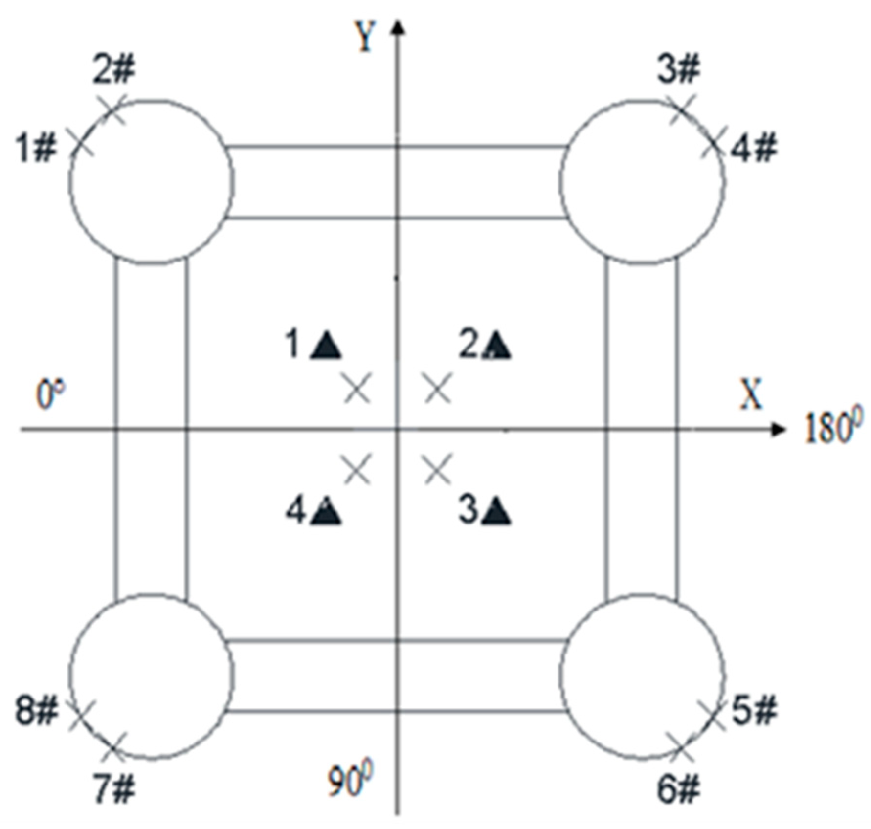
2.1. Test Model and Test Device

The schematic diagram, test layout and coordinate system of the pool test device of the tension leg platform system are shown in Figure 1 and Figure 2.
As shown in Figure 1 and Figure 2, the full-depth mooring pool test device model of the tension leg platform includes TLP main body, eight tension legs (In Figure 2, 1# to 8# are shown) and 4 TTR risers (In Figure 2, 1▲ to 4▲ are shown). The scale parameters of the tension leg platform and model are shown in Table 1. The effective working size of the model test pool is 456 m × 5 m × 12 m, and the scale ratio of the test model is 1:61. This scale can meet the similar requirements and the water depth requirements of the large-scale wave pool test, and the full-depth simulation test can be conducted without truncation.

2.2. Test Conditions

The full-depth mooring tank test of the tension leg platform mainly studies the vortex-induced motion of the floating body and the response characteristics of the vortex-induced vibration of the pipe string of the tension leg platform under different flow direction angles and different velocities. Three flow directions were selected, 0°, 22.5°, and 45°, respectively. Each flow direction angle takes 10 different flow velocities. The converted speed range of each flow rate is 4–12. Such velocity range basically covers the target sea area once a year (surface velocity 1.5 m/s), once a decade (surface velocity 1.7 m/s) and once a century (surface velocity 2.3 m/s). The wave environment is a regular wave.
The TLP attenuation test was carried out before the formal test, and TLP natural frequency was obtained through the test. According to the attenuation curve drawn from the attenuation test, the model sway period value was 11.20 s, the natural frequency was 0.089 Hz, the model surge period value was 11.03 s, and the natural frequency was 0.091 Hz.

3. Tension Response Analysis of Tension Leg and Riser under Uniform Flow

In the model test, the response characteristics of flow velocity to the vortex-induced motion of the floating body, the vortex-induced vibration of the tension leg and riser under uniform flow are studied, and three flow directions of 0°, 22.5°, and 45° are selected in the test. The influence of flow direction and velocity on the vortex-induced motion of the floating body, and the vortex-induced vibration of the tension leg and riser under uniform flow is obtained through experiments. The upper end-points of the tension leg and riser are hinged with the floating body, and they have the same motion track as the floating body movement. Their interaction can be studied by comparing the test results of the vortex-induced motion of the floating body with the vortex-induced vibration of the tension leg and riser.

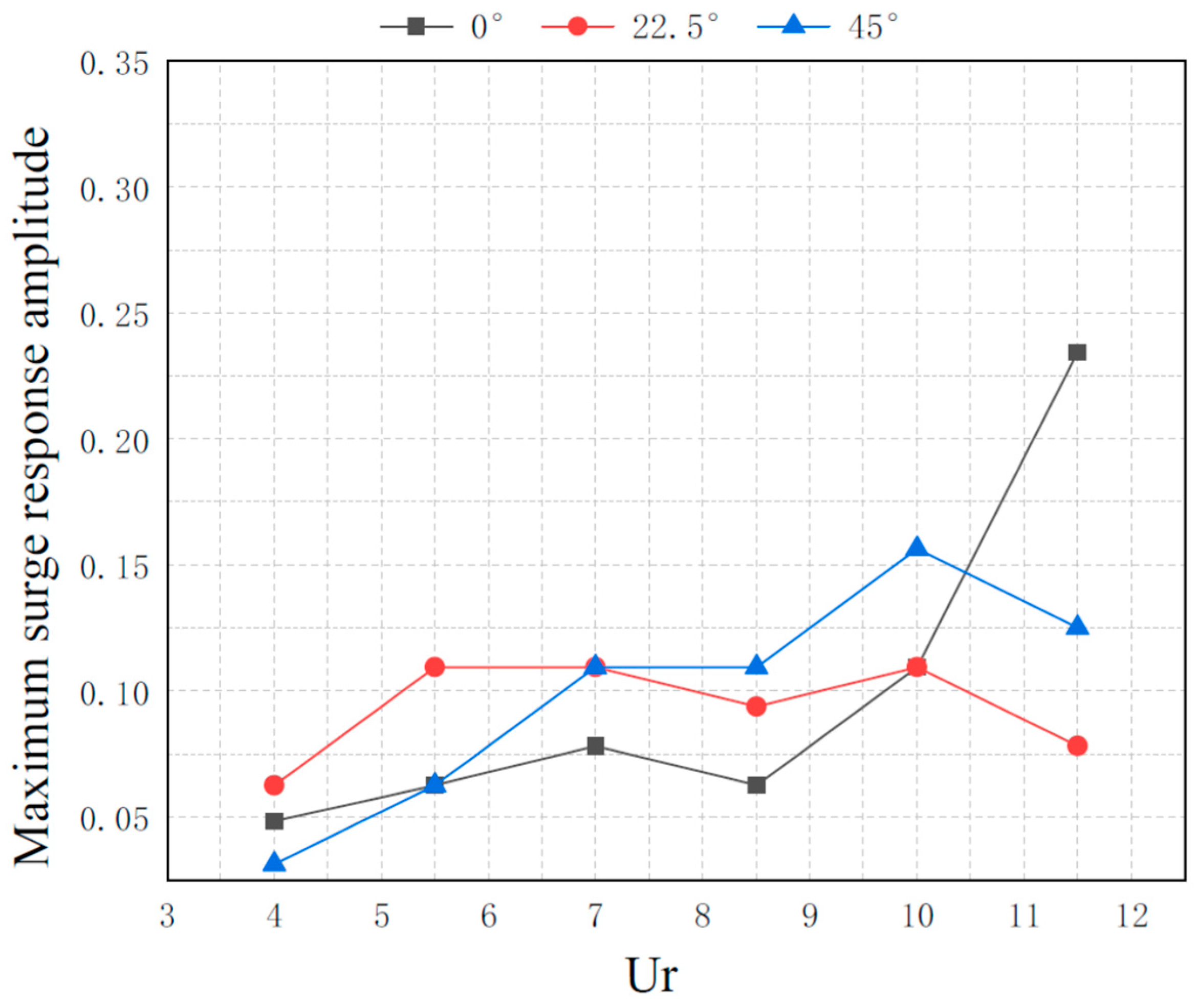
3.1. Vortex-Induced Motion Response of Platform Floating Body under Uniform Flow

Figure 3 and Figure 4 show the maximum response amplitudes of the floating body in transverse/surge at three flow angles. The abscissa Ur in the figure is the reduced speed (Ur = UT/D, U is the inflow velocity, T is the sway period of the structure, and D is the diameter of the column. Ur is dimensionless). The maximum response amplitude in the figure is the ratio of amplitude to column diameter, dimensionless. Figure 5 shows the trajectory of the floating body in the XY plane at three inflow angles, Ur = 7.
Figure 3 and Figure 4 show the response of floating bodies to uniform flow at different velocities and directions. As shown in Figure 3, under the three flow angles, the lateral motion response of the platform is the most significant in the range of 5.5 < Ur < 8.5. According to the attenuation curve drawn from the attenuation test, the model sway’s natural frequency is 0.089 Hz. If the platform’s sway motion frequency is close to 0.089 Hz, resonance occurs. This reduced speed interval is called the locking interval of the platform vortex-induced motion. With the increase of the reduced speed, the sway response began to decline. For the comparison of sway amplitude under three flow angles, when the flow angle is 0°, the sway vortex-induced motion response is the largest. At the 22.5° flow angle, the response amplitude is the second. When the flow angle is 45°, the platform sway vortex-induced motion response is the smallest. At the 45° inflow angle, the distance between the rear column and the front column and the distance between the columns in the width direction are both large, and their respective wake vortices have little influence. The vorticity intensity of the flow field where the platform is located is small, so the amplitude of transverse vortex excitation is the smallest. As shown in Figure 4, the surge motion response amplitudes are different under different inflow angles, and the influence of inflow angles on surge motion is reflected in the projected area of the floating body on the flow direction plane. Unlike the sway motion, the surge amplitude increases with the increase of the incoming flow velocity. For the inflow angles of 22.5°and 45°, the amplitude decreases after the lock zone. The general trend is that the surge response of the floating body increases with the increase of the flow velocity, and there is no significant increase in the sway lock zone.
As shown in Figure 5, the structure of the floating body itself is symmetrical at 0° and 45° inflow angles. At this time, the response in the CF direction is far greater than that in the IL direction, so the platform trajectory is in the shape of a symmetrical structure “8”. When the angle is 22.5°, the structure of the platform itself is asymmetric, but the responses of the CF and the IL directions are closer, and the motion trajectory presents an asymmetric structure. Therefore, the fullness and flatness of the floating body’s motion track are determined by the magnitude of the IL response and the CF response.
The upper endpoints of the tension leg and riser move together with the floating body. The velocity, acceleration and trajectory of the upper endpoints have a great impact on the vortex-induced vibration of the tension leg and riser, mainly on the vibration mode and amplitude.

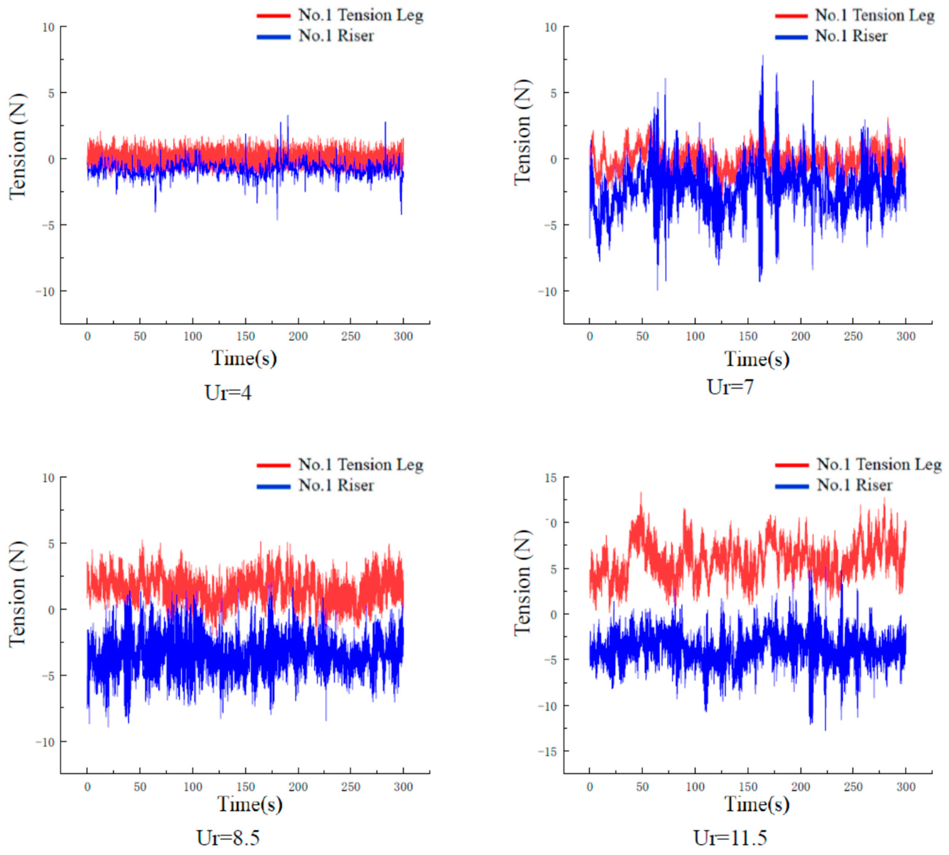
3.2. Tension Response of Tension Leg and Riser under Uniform Flow

Figure 6 shows the time history response curve of tension of the No. 1 tension leg and No. 1 riser under different reduced speeds of 0° incoming flow. It should be noted that The time history ordinate values shown in Figure 6 are relative values. After the tension leg and riser are installed, they should be pre-tensioned. At the position where the ordinate is 0, the tension of the tension leg and riser is not 0.
As shown in Figure 6, under the action of the downstream flow force, the floating body shifts to a new equilibrium position. Due to the constraints of tension legs and risers, the floating body can only make periodic movements at the new equilibrium position. The motion track is shown in Figure 6. The surge and sway amplitude of the floating body depends on the flow velocity and the angle of arrival. Due to the floating body traction, the tension on the tension leg and riser also periodically changes at the new equilibrium position.
The comparison between the tension amplitude change and the sway amplitude of the tension leg is shown in Figure 7, and the change of tension amplitude of the tension leg and riser with converted speed is shown in Figure 8.
As shown in Figure 7, under the condition of medium and low reduced speeds, the tension of the tension leg increases with the increase of flow rate, but the tension of the tension leg does not appear extreme near Ur = 7 in the locking range but increases with the increase of flow rate. It can be seen that the locking of the vortex-induced motion of the floating body does not lead to the increase of tension leg and riser tension. Figure 8 shows that the tension of tension legs and risers is greatly affected by the flow rate, which increases nonlinearly with the increase of the flow rate. At high flow velocity, the platform has a large longitudinal displacement, and the whole system deviates from the initial position to a great extent, leading to an increase in the tension value. In addition, tension legs and risers can limit the movement of the floating body. Tension legs and risers can provide greater restoring force and effectively control the amplitude of vortex-induced motion of the floating body.

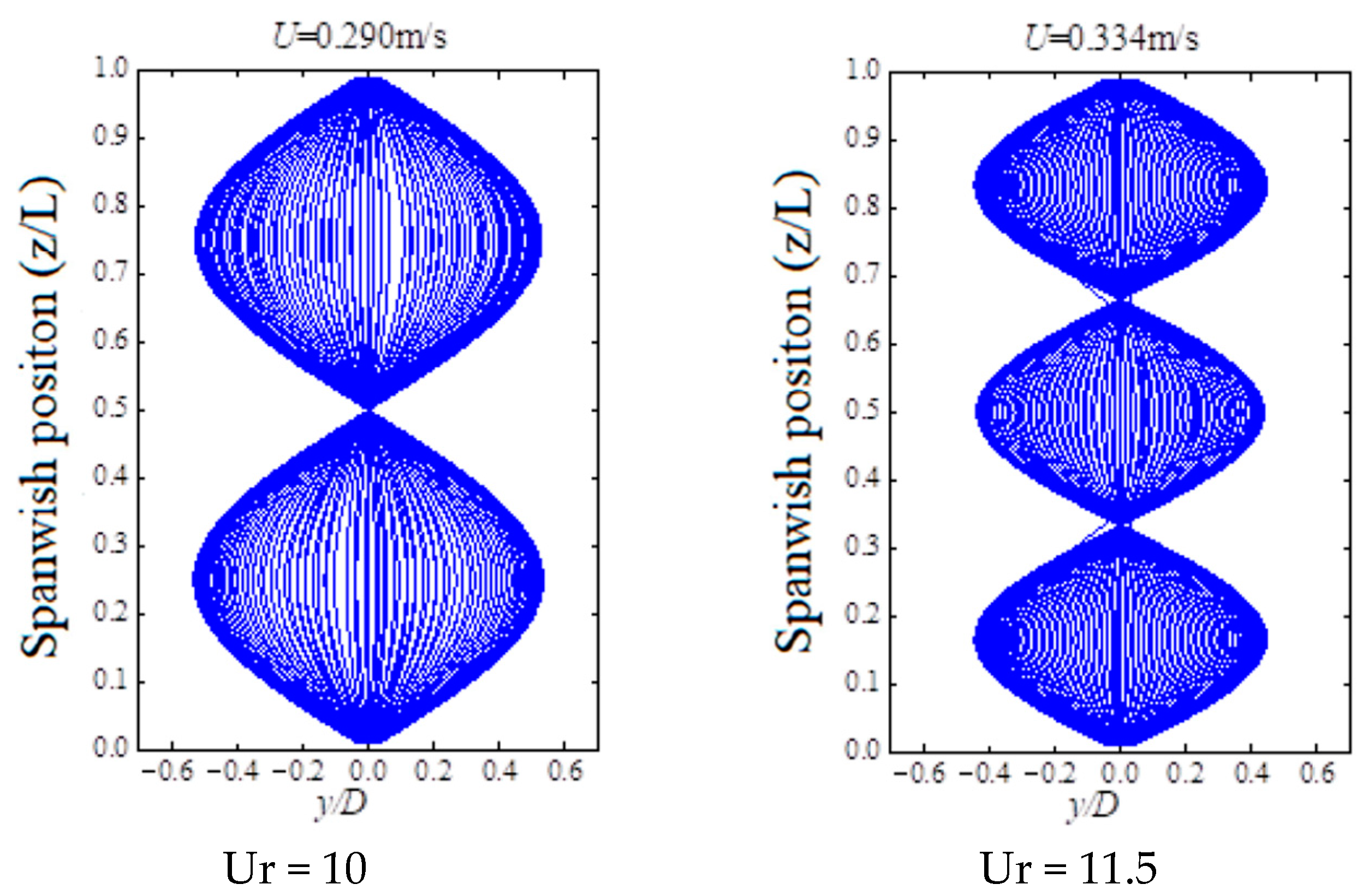
4. Mode and Displacement Response of Tension Leg and Riser

Tension legs and risers are slender structures. Vortex-induced vibration will occur under the action of ocean current. Vortex-induced vibration is the local vibration of the pipe structure. The vibration mode and amplitude depend on the flow velocity along the pipe span, the flow velocity distribution, the pretension, and the movement state of the upper endpoint or the floating body movement. The parameters such as tension and displacement of tension leg and riser are measured by the model test. Through the statistical analysis, the modal and displacement response results of the tension leg and riser are given. Figure 9 and Figure 10 show the displacement modal response of the No. 4 tension leg (downstream tension leg in the inflow direction) at different inflow angles when Ur is 7 (U = 0.203 m/s) and 8.5 (U = 0.247 m/s).
As shown in Figure 9, when the inflow velocity is Ur = 7, the response envelope diagrams of vortex-induced vibration of No. 4 tension leg at the inflow angles of 0°, 22.5° and 45° are all half symmetrical sine waves, which indicates that the first mode of tension leg dominates the vortex-induced vibration response at this flow velocity.
As shown in Figure 10, when the external inflow velocity is Ur = 8.5, the No. 4 tension leg is still in the first-order mode under the condition of 0° inflow. Under the conditions of 22.5° and 45° incoming flow, the envelope diagram of the vortex-induced vibration response state is shown as a state of transition from half a sine wave to a complete symmetrical sine wave, approaching the second mode, and where the second mode dominates vortex-induced vibration response. For a single tension leg, since its structural model is a highly symmetrical circular tube, the flow direction has no effect on a single tube. However, it can be clearly seen from the data results that the response of the tension leg is different under different inflow angles. The main reasons for the difference are: (1) After the water flows through the tension leg, vortex shedding and other complex flow field phenomena occur. For this test condition, at 0° inflow angle after the water flows through the upstream tension leg, the shedding vortex will directly affect the No. 4 tension leg directly behind it, producing a shielding effect, and the flow rate will decrease slightly. Therefore, the displacement mode of the No. 4 tension leg still presents a first-order mode. Under the conditions of 22.5° and 45°inflow, the distance between the front and rear tension legs and the width direction are large without shielding, and the increase of the downstream tension leg velocity causes the first- and second-order modes to dominate alternately. (2) The response mode number of vortex-induced vibration of pipe structure is not only related to the flow velocity but also to the top pretension. According to the results of the vortex-induced motion response of the floating body, the response amplitude of the sway motion of the floating body at 0° inflow angle is greater than that at 22.5° and 45° inflow angles. Therefore, the coupling effect between the floating body and the tension leg is more intense. Under the condition of 0° inflow, the top pretension of the tension leg is always greater than the other two working conditions. With the increase of the top pretension, the amplitude of the tension leg structure decreases, and the mode decreases accordingly. Therefore, when Ur is 7 at 0° inflow angle, the tension leg is always in the first mode dominant state.
Figure 11 shows the displacement modal response of the No. 4 tension leg under different flow velocities at 0° inflow angle.
As shown in Figure 9, Figure 10 and Figure 11, the main control mode of vortex-induced vibration of the tension leg increases with the increase of flow velocity at 0° inflow angle. Due to the wake shielding effect of the No. 1 tension leg, the local flow velocity of the No. 4 tension leg is reduced, which leads to a large conversion speed when the control mode is converted from the first order to the second order.
As shown in Figure 12, with the increase in the incoming flow velocity, the main control mode of vortex-induced vibration of the riser structure is improved. Due to the low top tension of the riser, the highest mode can reach seven orders. Due to its large length diameter ratio and low mass ratio, the riser structure is very easy to excite higher-order modes or even produce multi-mode mixing under the action of external flow. When Ur is 5.5, the main control mode of the riser is converted from the fourth order to the fifth order, in which there is a mixture of the fourth and fifth order modes. When Ur is 11.5, the original 7-order mode of the riser has a component of the higher-order mode, and the control mode will rise again with the increase in flow rate. Corresponding to different modal orders, the displacement amplitude of the riser is larger than that of the tension leg, mainly because the top tension of the riser is smaller and the quality is lower.

5. Tension Response of Tension Leg and Riser under Combined Action of Wave and Current

The vortex-induced motion of the floating body under the combined action of uniform flow and regular wave, as well as the vortex-induced vibration of the tension leg and riser, are studied experimentally, and the test results are analyzed. In the model test, regular waves with a wave period of 2.82 s, wave height of 0.246 m, uniform flow with reduced velocity Ur = 5.5 and action direction of 45° are selected. The results of the model test are shown in Table 2.
According to Table 2, regular waves can reduce the flow-induced vortex-induced motion in the sway direction, and different regular waves have different effects on the vortex-induced motion in the sway direction. In general, the motion response in the sway direction is basically low-frequency motion caused by vortex-shedding excitation, and the motion caused by waves only accounts for a very small part. In terms of surge response, the action of regular waves leads to periodic wave frequency response of the platform. The wave frequency motion is caused by waves, and vortex-induced motion is caused by currents overlapping each other, increasing the amplitude of the surge motion response of the platform. Similar to the motion law of the floating body, under the combined action of wave and current, the surge, heave and downstream drift of the platform will cause the tension of tension legs and risers to rise significantly. According to the statistics of wave current joint test results, under the action of regular waves, the maximum tension of the tension leg is 112.48 N, and the maximum tension of the riser is 40.1 N. Compared with the action of the current, the tension of the tension leg is increased by 5%, and the tension of the riser is increased by 30%. Under the combined action of wave and current, the maximum tension of the tension leg reaches 120.77 N, and the maximum tension of the riser reaches 45 N. Compared with the action of a single flow, the tension of the tension leg increases by 14%, and the mooring force of the riser increases by 49%. The test results show that after the wave action is added to the test, the lateral motion of the floating body will be greatly reduced. The displacement of the floating body in the sway direction has little effect on the force on the tension legs and risers. The rise of the force on the tension legs and risers can be seen as the increase of the drag force on the floating body in the flow direction and the tension change caused by a certain degree of heave movement. Under the action of waves, the forces on tension legs and risers increase. Among them, the amplitude of the tension leg is small, and the force on each tension leg is uneven, which is closely related to the direction of the incoming flow and the direction of the floating body drift downstream. The tension of the riser increases greatly, and the force on each riser is relatively average.

6. Conclusions

Taking the traditional tension leg platform as the research object, the model test of a full-depth mooring tension leg platform under the combined action of uniform flow and wave current is carried out in this paper. Based on the test results, the response characteristics of tension leg and riser vortex-induced vibration under the combined action of uniform flow and wave current and the influence of floating body motion on the response of tension leg and riser vortex-induced vibration are analyzed. The main conclusions are as follows:
(1) Under the action of uniform flow, the lock range of vortex-induced motion of the floating body in sway is 5.5 < Ur < 8.5. Surge motion increases with increasing velocity. At 0° and 45° inflow angles, the CF response of the floating body is far greater than the IL response, and the symmetry effect of the flow makes the floating body track appear symmetrical “8” shape;
(2) Under the action of the IL flow force, the floating body moves to a new equilibrium position. Because of the floating body’s traction, the tension on the tension leg and riser also periodically changes at the new equilibrium position. The tension of tension legs and risers is greatly affected by the flow velocity, which increases nonlinearly with the increase of the flow velocity. The tension leg and riser can provide a large restoring force, which can effectively control the amplitude of the vortex-induced motion of the floating body;
(3) The displacement mode of the tension leg and riser is greatly affected by the flow velocity, and the mode order increases with the increase of flow velocity. In addition, the displacement amplitude of the tension leg and riser decreases to a certain extent due to the increase of tension generated by the large displacement of the floating body;
(4) The wave can reduce the sway of the floating body and strengthen the surge. Therefore, the tension amplitude of the tension leg and riser increases under the combined action of wave and current due to the traction of the floating body.

Author Contributions

Conceptualization, R.C.; Data curation, H.Q.; Formal analysis, Y.W.; Supervision, S.W.; Validation, H.L.; Writing—original draft, W.Z.; Writing—review & editing, M.D. All authors have read and agreed to the published version of the manuscript.

Funding

This research was funded by the National Natural Science Foundation of China (Grant No. 51879271) and China National Science and Technology Major Special Project “Deepwater platform Engineering Technology” (2016ZX05028-002).

Institutional Review Board Statement

Not applicable.

Informed Consent Statement

Not applicable.

Data Availability Statement

All data in this study has been included in this paper.

Conflicts of Interest

The authors declare no conflict of interest.

References

  1. Liu, G.; Li, H.; Qiu, Z.; Leng, D.; Li, Z.; Li, W. A mini review of recent progress on vortex-induced vibrations of marine risers. Ocean Eng. 2020, 195, 106704. [Google Scholar] [CrossRef]
  2. Wan, D.; Duan, M. Research progress of numerical analysis methods for vortex induced vibration of deep-sea slender flexible risers. Mech. Q. 2017, 38, 179–196. [Google Scholar]
  3. Huang, X.; Zhang, H.; Wang, X. Research Status, Hotspots and Prospects of Vortex Induced Vibration in Marine Risers. Oceanogr. Res. 2009, 27, 94–101. [Google Scholar]
  4. Yin, B.; Hu, Q.; Li, Y.; Wang, W.; Zhu, J.; Wang, D. Review of Research on Vortex Induced Vibration Characteristics of Marine Risers. Ship Mech. 2022, 26, 1097–1109. [Google Scholar]
  5. Chen, W.; Zheng, Z.; Guo, S. Influence of sway motion of floating platform on vortex induced vibration of underwater flexible riser. Offshore Eng. 2014, 32, 8–13. [Google Scholar]
  6. Song, L.; Fu, S.; Ren, T.; Yu, D.; Zhang, M. Research on vortex induced vibration response and vortex induced force load characteristics of flexible riser under uniform flow. Ship Dyn. 2017, 36, 14–21. [Google Scholar]
  7. Gao, Y.; Ren, T.; Fu, S.; Xiong, Y.; Zhao, Y. Experimental study on vortex induced vibration response characteristics of flexible riser. Vib. Impact 2015, 34, 6–11. [Google Scholar]
  8. Gao, Y.; Liu, L.; Fu, S.; Zong, Z.; Zou, L. Study on the trajectory characteristics of vortex induced vibration response of flexible risers. Ship Mech. 2017, 21, 563–574. [Google Scholar]
  9. Kurushina, V.; Pavlovskaia, E.; Wiercigroch, M. VIV of flexible structures in 2D uniform flow. Int. J. Eng. Sci. 2020, 150, 103211. [Google Scholar] [CrossRef]
  10. Ulveseter, J.V.; Thorsen, M.J.; Larsen, C.M. Time domain simulation of riser VIV in current and irregular waves. Mar. Struct. 2018, 60, 241–260. [Google Scholar] [CrossRef]
Figure 1. Schematic Diagram of Full Depth Mooring Test.
Jmse 11 00180 g001
Figure 2. Test arrangement and coordinate system.
Jmse 11 00180 g002
Figure 3. Maximum response amplitude of floating body sway under three flow angles.
Jmse 11 00180 g003
Figure 4. Maximum response amplitude of floating body surge under three flow angles.
Jmse 11 00180 g004
Figure 5. The trajectories of floating bodies with three inflow angles in XY plane.
Jmse 11 00180 g005
Figure 6. Time history response curve of tension of No. 1 tension leg and No. 1 riser.
Jmse 11 00180 g006
Figure 7. Comparison of tension leg tension amplitude change and sway.
Jmse 11 00180 g007
Figure 8. Variation of tension amplitude of tension leg and riser with the reduced speed.
Jmse 11 00180 g008
Figure 9. Displacement modal response of No. 4 tension leg with Ur = 7 under different inflow angles.
Jmse 11 00180 g009
Figure 10. Displacement modal response of No. 4 tension leg under different inflow angles with Ur = 8.5.
Jmse 11 00180 g010
Figure 11. Displacement Modal Response of No. 4 Tension Leg at 0° Inflow Angle and Different Flow Velocity.
Jmse 11 00180 g011
Figure 12. Modal Response of Riser under Different Flow Velocity at 0°.
Jmse 11 00180 g012
Table 1. Tension Leg Platform and Model Scale Parameters.
ParameterReal ValueModel Value
Column diameter/m19.50.320
Pontoon height/width/m8.5/8.50.139/0.139
Column center distance/m590.976
Draft/depth/m30.5/404.70.500
Displacement/KG49,235,000211.622
Weight/KG31,847,000136.885
Height of gravity center/m43.160.708
Table 2. Results of wave current joint model test.
Test ConditionsSway Amplitude/(m)Surge Amplitude/(m)
Wave current combination2.57015.024
Uniform flow414.462
Disclaimer/Publisher’s Note: The statements, opinions and data contained in all publications are solely those of the individual author(s) and contributor(s) and not of MDPI and/or the editor(s). MDPI and/or the editor(s) disclaim responsibility for any injury to people or property resulting from any ideas, methods, instructions or products referred to in the content.

