
Ultimate Strength Behaviour and Optimization of Laser-Welded Web-Core Sandwich Panels under In-Plane Compression


Centre for Marine Technology and Ocean Engineering (CENTEC), Instituto Superior Técnico, Universidade de Lisboa, 1049-001 Lisboa, Portugal
*
Author to whom correspondence should be addressed.
J. Mar. Sci. Eng. 2023, 11(11), 2200; https://doi.org/10.3390/jmse11112200
Submission received: 26 September 2023
/
Revised: 31 October 2023
/
Accepted: 14 November 2023
/
Published: 19 November 2023
(This article belongs to the Special Issue The 9th International Conference on Marine Structures (MARSTRUCT 2023))
Abstract
:In pursuit of more efficient load-bearing solutions for ship deck panels of Very Large Crude Carriers exposed to vertical hull girder bending forces, laser-welded web-core sandwich panels are considered as an alternative to conventional stiffened panels. The primary goal is to identify a lighter steel sandwich structure capable of matching the ultimate strength of conventional counterparts. Utilizing non-linear finite element analysis, the ultimate strength of conventional decks subjected to uniaxial compression is assessed. Attention is then shifted to laser-welded sandwich panels, with a detailed examination of how various design parameters influence their performance. Specifically, four key design aspects of unidirectional vertical webs, including face thickness, web thickness, web height, and web spacing, are optimized to strike a balance between weight and strength through structural optimization techniques combined with the response surface method. Ultimately, a comparison is drawn between the ultimate strength of these innovative steel sandwich panels and their conventional, stiffened counterparts. The findings reveal that web-core sandwich panels, when employed as an alternative, result in a notable reduction in hull weight, thereby showcasing the potential for a more efficient and sustainable approach in the maritime industry.
1. Introduction
Light-weight sandwich structures have become more widely used recently in a range of industrial applications, such as aerospace, automotive, offshore and shipbuilding [1,2,3]. The use of sandwich structures can result in significant weight savings and improved performance, making them an attractive option for many engineering applications. These structures are characterized by a common feature of two facing sheets separated by a core layer. Face sheets of sandwich panels contribute to structural rigidity and shield the core from damage. Substantial bending stiffness is attained under loading conditions, as the face sheets bear both compressive and tensile loads, while the core absorbs shear stresses generated by transverse forces and provides support to prevent the skins from buckling [4,5,6].
Sandwich constructions can be classified as all metal which consists of a core made of steel or aluminium and the faces made of the same metal [7,8]. Another type is hybrid metal, which is a blend of materials, comprising both metals and non-metals, where facing sheets are made from metallic materials but the core is made from composite materials. Finally, composite sandwich panels which have face sheets made from a composite material [9,10,11] are also available in all composite ships [12] or in hybrid ships with steel and composites [13,14].
Comparing sandwich constructions to conventional steel structures, there are various benefits, such as simplified structure, reduced weight [15,16,17], and improved fatigue resistance [18]. Other advantages are provided in specific applications, such as heat insulating performance [19], improved impact strength [20], and blast and ballistic resistance [21]. Each of these results in lower production costs and a longer, safer service life [22].
In a study concerning the ultimate strength of laser-welded sandwich structures, Kozak [23] conducted a series of experiments and numerical simulations to examine the ultimate strength of steel sandwich beams. The findings revealed that the failure modes exhibited variation depending on the specific cross-sections of the plates. Kolsters and Zenkert [24] extended the buckling model to the elastic–plastic regime to ascertain the maximum strength of sandwich plates. To substantiate the results, experimental tests were conducted to examine the disparity in load-carrying capacity between a web-core sandwich panel and a stiffened plate when subjected to axial loading in the direction of the web stiffener. Jelovica and Romanoff [25,26] conducted analytical and numerical studies to investigate the bifurcation buckling behaviour of sandwich panels with unidirectional stiffeners.
Buckling analysis and non-linear finite element analysis were performed under in-plane ultimate unidirectional compression for metal sandwich panels, V-type and I-type metal corrugated sandwich panel structures, and combined with the conventional stiffened plate structure. The weight reduction of I-type metal corrugated sandwich panels is higher than the stiffened panel and V-type metal corrugated sandwich panel [27]. A numerical study was conducted to investigate the ultimate strength characteristics of web-core sandwich plates joined with laser welding and subjected to in-plane compression. This investigation took into account the influence of initial deflections, boundary conditions, and the stiffness associated with the rotation of the laser weld [28]. In the work conducted by Zhong et al. [29], an investigation was conducted on the ultimate strength and collapse behaviour of the hull girder, considering the presence of an upper sandwich deck and its exposure to vertical bending, horizontal bending, torsion, and combinations of these loads. Through numerical analyses, the study successfully established and rigorously validated the correlations between the ultimate strength and interactions for hull girders subjected to combined two moments or combined three moments.
The present study makes use of innovative stiffener cross-sections made of laser-welded vertical web sandwich panels in an effort to increase the ultimate strength to weight ratio of ship structures. Non-linear finite element analysis (NLFEA) is used for the assessment of the ultimate strength and maximum load carrying capacity of a stiffened panel from the deck of a double-hull Very Large Crude Carrier (VLCC) under in-plane compression. For that purpose, ANSYS (2022 R2) software is used. An equivalent vertical web panel is obtained based on optimization using the response surface method (RSM) with ANSYS DesignXplorer software. The findings obtained using NLFEA of laser-welded web-core sandwich panels subjected to uniaxial compressive loading are presented. The selection of the specific numerical analyses is determined by the design of experiments (DOE) methodology. These NLFEA findings form the basis for developing the mathematical models required for the implementation of response surface methodology (RSM). These models are employed for design optimization using genetic algorithms (GA) with the aim of predicting the optimal configuration of vertical web sandwich panels that have a minimum weight and strength equivalent to those of conventional panels.
2. Case Study
The selection of the model to be used is one of the parts of this study that inspires more concerns to achieve the most reliable results. In the current study, longitudinal stiffened deck panels at the centre tank of a double-hull Very Large Crude Carrier (VLCC) are taken into consideration. Table 1 and Figure 1 provide a summary of the midship section and the key features of the VLCC.
This research concentrates on one-bay deck panels. The geometrical features of the deck panels with the conventional T-stiffeners are shown in Figure 2.
The proposed vertical web sandwich panel is optimized to obtain the lightest panel that has the same ultimate strength as a conventional one. In order to obtain the response surfaces, a grid of 144 design points is generated for the four input parameters shown in Figure 3. Parameter identification plays a vital role as it establishes the crucial input parameters affecting the model’s output variables. The design space remains constant. A comprehensive design approach is being utilized, where all feasible parameter values are systematically varied across a grid. This method is employed to ensure an exhaustive exploration of the parameter space, leaving no potential values untested. The intervals for the input parameters are determined as follows:
| [8–12 mm] with increment of 2 mm. |
| [6–12 mm] with increment of 2 mm. |
| [100–200 mm] with increment of 50 mm. |
| [100–400 mm] with increment of 100 mm. |
3. Finite Element Modelling
The significance of determining the ultimate strength in structural elements and systems is crucial, as it corresponds to their maximum load bearing capacity [30]. Over time, research into buckling and ultimate strength concerns in ship structures has been widely conducted using various methods, including analytical approaches [31], simplified numerical methods [32], experimental tests [33], and empirical studies. The capabilities of non-linear finite element analysis have seen significant progress in recent years, primarily driven by advances in computing power [34]. Numerical techniques have now become an invaluable part of most structural research. Utilizing the finite element method for thin-walled structures frequently necessitates the use of non-linear analysis. The problem of ultimate strength assessment using NLFEA has clear and validated procedures for the assessment of buckling and ultimate strength capacities of stiffened panels, which have been widely used for conventional stiffened panels [35,36].
The present study performs NLFEA to investigate the uniaxial compressive capacity of vertical web sandwich panels, which is compared with that of the conventionally stiffened panels. A linear eigen-value analysis is performed to define the initial global imperfections that will be used later in the stiffened plate’s non-linear buckling analysis. The eigenmodes determined from the linear buckling analysis are used to prepare the originally deformed model that will be used in the non-linear analysis as input. The process of initializing linear buckling solutions starts with a prescribed initial out-of-plane deflection with the shape of the panel’s first eigenmode under a compression load and an amplitude of 1 mm. This method considers the unit approach eigenmode as a reference for assessing the panel’s response to compression. Only global deflections are considered because the laser welding due to its concentrated heat input does not induce significant residual stresses and permanent local deflections that are typical in steel stiffened panels [37]. The load-shortening curve (LSC) depicts the unidirectional shortening of a stiffened panel, resulting from the imposition of a compressive load oriented in the corresponding direction. The highest point on the LSC is the onset of panel collapse, as a significant decrease in the panel’s resistance to compressive stress immediately follows it. Thus, it represents the panel’s ultimate buckling capacity. The main steps of the analysis are summarized in the flowchart in Figure 4.
3.1. Numerical Model Characteristics
ANSYS Design Modeler Software is used for modelling. The choice is made to employ the SHELL181 element from the ANSYS element library to discretize the stiffened plate models into structural elements. SHELL181 is particularly suitable for applications involving linearity, significant rotations, and/or substantial strain non-linearity. This element comprises four nodes, and each node has six degrees of freedom: translations along the x, y, and z axes, as well as rotations about the x, y, and z axes. The element has plasticity, viscoelasticity, stress stiffening, large deflection, and large strain capabilities. The same steel grade is used for both conventional and sandwich panels (faces and longitudinal webs) as indicated in Table 2. It is assumed that the stress–strain curve follows an idealized elastic, perfectly plastic behaviour, without considering any material hardening effects as shown in Figure 5.
3.2. Boundary Conditions and Loading
To simulate longitudinal bending, the degrees of freedom of all nodes on the fore, aft, and side edges of the model are defined. The nodes of the end cross sections of the stiffeners are subjected to the same boundary conditions as their corresponding plate edge. The implementation of the appropriate boundary conditions for a load case is shown in Figure 6. The boundary conditions are established to involve displacement constraints along the X, Y, and Z axes, labelled as Dx, Dy, and Dz, correspondingly. These constraints dictate how the structure is fixed or restrained in these particular directions. For instance, Dx signifies the displacement along the X axis, Dy signifies the displacement along the Y axis, and Dz corresponds to the displacement along the Z axis. The same boundary conditions are applied for all models. For the derivation of the load end-shortening curves and the estimation of the ultimate buckling capacity, the load is introduced as a forced displacement on the fore or aft edge of the model and the corresponding reaction force on the opposite edge is calculated. The magnitude of the imposed displacement should be adequately large to produce sufficient deformation beyond the ultimate buckling capacity of the panel.
3.3. Initial Imperfections
Initial imperfections can be caused by a variety of factors, including the quality of the base materials, the manufacturing process, and the welding process itself [38]. The initial deflections have a significant impact on the ultimate strength analysis of ship hull structures, and should be accounted for in the ultimate strength assessment [39,40]. Recent research indicates that the influence of welding residual stresses with an average value on the ultimate strength of structures is relatively limited [41]. The energy concentration in laser welding far surpasses that found in conventional welding techniques like flame cutting and fusion welding, and the heat-affected zone is relatively small [29]. By utilizing laser welding, the focused energy of the laser beam is harnessed to rapidly vaporize the material undergoing the welding process. This produces the characteristic keyhole and the elongated, thin shape typically associated with laser welds. Another advantage of laser welding is its capacity to achieve significantly higher welding speeds when compared to the conventional arc welding techniques. Generally, panels welded using this approach display reduced welding distortions and offer improved flatness in contrast to conventional structures [9,15].
The shape of the first eigenmode can be introduced as an initial imperfection [42]. Two primary categories of initial deflection are under scrutiny: localized deflections occurring within the face plates and the global deflection observed across the sandwich plate. In the latter case, this deflection exhibits a global characteristic, manifesting a singular half-wave pattern along both the longitudinal and transverse axes. On the other hand, the localized deflections within the face plates encompass symmetric and asymmetric variations relative to the geometric mid-plane, as depicted in Figure 7.
The initial deflections are provided as follows:
- Local deflection of the sandwich plate:
- Symmetric local deflections of the face plates;
- Asymmetric local deflections of the face plates.
- Global deflection of the sandwich plate.
3.4. Validation of the Applied Procedure
To validate the suggested methodologies, a comparison is made with relevant published results such as those of Khan and Zhang [45]. The attributes of the stiffened panel employed for validating the established numerical methodologies are outlined in Table 3. The load end-shortening curve derived from the non-linear finite element analysis performed in this study can be contrasted with the one depicted in Figure 8. The comparison of the ultimate load is very good, and the post-buckling behaviour can be considered satisfactory, given that different software and initial imperfections have been used. Furthermore, different iterative schemes have been used, where Khan and Zhang [45] used static Riks arc-length iteration scheme while the present work used Newton–Raphson equilibrium iterations.
3.5. NLFEA Results for Sandwich Panels
Figure 9 displays the FE method findings prior to running the numerical simulation. A total of 144 numerical analysis are conducted to obtain the ultimate strength of vertical web sandwich panels under longitudinal compression. The longitudinal direction describes the distance between the webs and webs’ height, which is divided into twelve sections. Each section contains twelve symbols according to face thickness and web thickness. The transverse direction describes the strain, and the vertical direction shows the axial compressive stress. As expected, ULS tends to decrease when the distance between the vertical webs is increased. Also, when the face sheet’s thickness or web’s thickness increases, the ULS tends to increase.
4. Optimization Analysis and Results
An optimal design of sandwich structures means finding sizes and materials that offer a minimum weight, maximum strength/stiffness, or minimal cost in relation to one or more constraints. The constraints in the different failure modes may be stiffness or strength, or a combination thereof.
Several methods for an optimal design of sandwich constructions are described. The optimization process used here is based on the response surface method (RSM), in which the results of the ultimate strength calculations are represented by polynomial functions, which avoid the need of performing a new NLFEA at each step of the optimization procedure [46].
RSM requires the design of experiments (DOE) method to determine the values of the various input parameters to be used in producing the output ones. After the finite element evaluation of the strength of the panels with each set of the input parameters, the outputs of each calculation are used to fit a full, second-degree polynomial response surface, generated for every output parameter. The response surface is used in connection with a genetic algorithm to determine the output value that corresponds to the optimum design.
Figure 10 shows the steps that are used in this study for the optimization of the web-core panels as an alternative to the conventional stiffened ones. The provided flowchart delineates a structured and rigorous pathway for achieving structural optimization. The study involves a systematic approach to optimize the structural performance of the panels. It begins by identifying crucial parameters, which are defined as face thickness (tf), web thickness (tw), web height (hc), and web spacing (S), that significantly impact structural behaviour. DOE techniques are then employed to methodically select input parameter values. Subsequently, NLFEA is conducted to simulate how the structures behave under various conditions for all DOEs. The optimization phase revolves around the constructed response surface to capture the intricate relationship between design variables and predefined objectives, such as maximizing structural strength or minimizing weights. This process leads to the identification of potential solution points within the design space, ultimately culminating in the selection of the most suitable solution.
With these four input parameters, a total of 144 distinct design points are generated, and the output parameters are computed using NLFEA. Local sensitivity pertains to the responsiveness of the objectives concerning structural parameters. A large local sensitivity indicates a more substantial impact of input parameters on the output strength. Moreover, the positive and negative distribution of sensitivity values signifies either the augmentation or attenuation of optimization objectives.
As shown in Figure 11, the distance between vertical webs (P4) has an obvious impact on ultimate axial load (P5) and weight (P6), and all are negatively interrelated. The web thickness (P1) has a greater influence on the weight (P6) parameter, while the effects on the ultimate axial load were relatively small. The effects of the web thickness (P2) and web height (P3) were normal.
The response surface optimization is performed utilizing the multi-objective genetic algorithm (MOGA) for the evaluation of the optimal design. The MOGA method is a variant derived from the widely used NSGA-II (non-dominated sorted genetic algorithm-II), incorporating controlled elitism principles. It is designed to handle problems with multiple objectives and constraints, with its primary objective being the identification of global optimum solutions [47,48]. The developed response surfaces are presented in Figure 12.
Goal-driven optimization (GDO) represents a constrained, multi-objective optimization approach that seeks to extract optimal designs from predefined sample sets, guided by user-defined objectives rooted in parameterized values. GDO encompasses various objective types, including no-objective, minimization, maximization, target values less than or equal to, and target values greater than or equal to the specified input target value.
As required, the ultimate axial load (P5) is set to be equal to 1.18 × 10⁸ N with this calculated for the conventional stiffened panel. Furthermore, the weight (P6) is set to minimize, where the weight of conventional stiffened panel equals 25.2 tons. The optimization process was set to generate the three best candidate points and the results are given in Table 4.
The primary aim of this research is to explore the replacement of conventional panels with vertical web-core sandwich panels possessing equivalent strength but reduced weight. For the panels considered here, the weight of the conventional panel equals 25.2-tons, while the weight of the optimized vertical web sandwich panels is reduced to 18.1-tons, as shown in Table 4. Therefore, a 7.1 ton reduction in weight is achieved based on the sandwich panel which is approximately 28%. This shows that it is possible to reduce the steel weight of the vessel by using web-core sandwich panels.
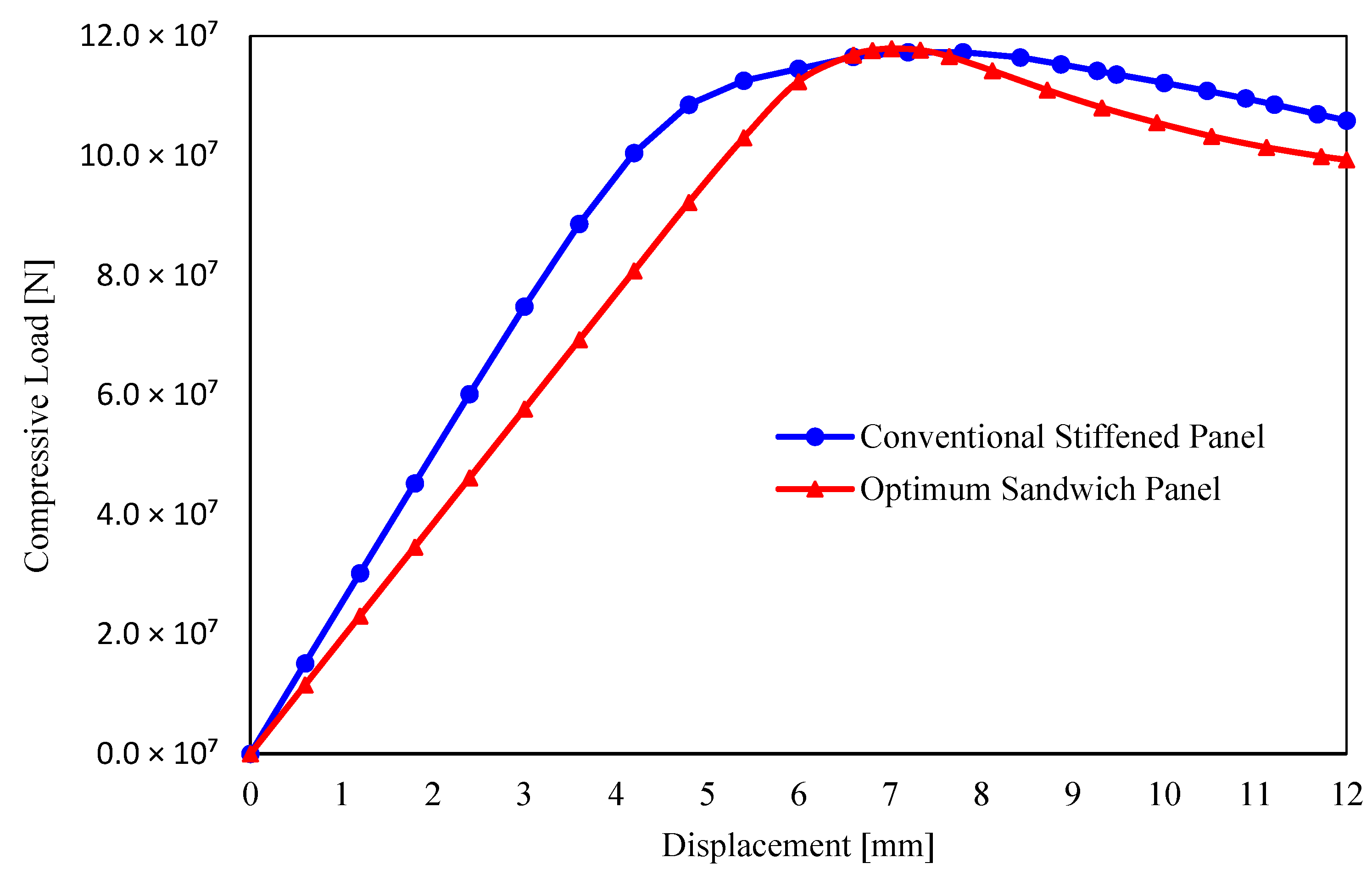
Figure 13 presents the curve depicting the compressive load (in N) plotted against displacement (in mm), which is derived from the non-linear finite element analysis performed in this study for conventional stiffened panels and compared with optimum sandwich panels obtained from the candidate points where face thickness tf = 8 mm, web thickness tw = 8 mm, web height hc = 100 mm, and web spacing S = 175 mm.
5. Conclusions
The primary focus of this research is on vertical web-core steel sandwich panels, with the aim of examining their ultimate compressive capacity while comparing weight reduction for the same ultimate load with conventional stiffened panels. Non-linear finite element analyses are conducted using the ANSYS (2022 R2) software to assess the load bearing capability of the proposed panels in comparison to a conventional panel when subjected to uniaxial compressive loading. The study involves 144 cases of numerical simulation results to ensure accuracy and relevance to the behaviour of the sandwich panels. The design parameters considered include face thickness, web thickness, web height, and the spacing between webs.
An optimization process is performed to seek the lightest sandwich panel that has a strength equivalent to that of a conventional one. Three web-core panels were concluded with 28% weight reduction as compared with an equivalent conventional panel. This shows that it is possible to reduce the steel weight of a vessel by using web-core sandwich panels.
The results are checked in order to ensure that the values of the chosen design parameters are the best candidates within the defined constraints. Based on the optimization results, it is concluded that face plate thickness should be 8 mm, the thickness of vertical webs should be 8 mm, the height of webs should be 100 mm, and web spacing should be 175 mm for the optimum design. According to the optimization results, a model that has an optimum cross-section thickness is designed and analysed. Figure 13 displays the load-shortening curve of the optimal sandwich panel alongside the conventional counterpart. As is evident in the figure, the strength of the optimal model matches that of the conventional one.
Local sensitivity analysis is a powerful tool in determining the influence of input parameters on output parameters in structural systems. By analysing the effect of changes in a specific parameter on the overall behaviour of the structure, local sensitivity analysis helps identify the most influential parameters that have a significant impact on structural performance. According to this study, it was found that the distance between vertical webs had a significant negative impact on both the ultimate axial load and weight parameters. In contrast, the web thickness had a greater influence on the weight parameter, with relatively little effect on the ultimate axial load. The effects of the web thickness and web height were within the expected range. These findings can inform the optimization and design of structural systems, enabling engineers to identify the most influential parameters and optimize them to achieve the desired performance with minimal material usage and cost.
Author Contributions
Conceptualization and methodology, M.E. and C.G.S.; formal analysis, validation, visualization, and writing—original draft M.E.; writing—review and editing, supervision, and funding acquisition, C.G.S. All authors have read and agreed to the published version of the manuscript.
Funding
This work was performed within the Strategic Research Plan of the Centre for Marine Technology and Ocean Engineering, financed by the Portuguese Foundation for Science and Technology (Fundação para a Ciência e Tecnologia—FCT) under contract UIDB/UIDP/00134/2020.
Institutional Review Board Statement
Not applicable.
Informed Consent Statement
Not applicable.
Data Availability Statement
Data are contained within the article.
Conflicts of Interest
The authors declare no conflict of interest.
References
- D’Alessandro, V.; Amabili, M.; De Rosa, S.; Franco, F. Preliminary identifications of sandwich panels. In Proceedings of the INTER-NOISE and NOISE-CON Congress and Conference Proceedings, New York, NY, USA, 19–22 August 2012; Institute of Noise Control Engineering: Washington, DC, USA, 2012; pp. 188–197. [Google Scholar]
- Ramnath, B.V.; Alagarraja, K.; Elanchezhian, C. Review on sandwich composite and their applications. Mater. Today Proc. 2019, 16, 859–864. [Google Scholar] [CrossRef]
- Elsaka, M.; Soares, C.G. Review of the structural configuration and strength of metallic sandwich panels. In Advances in the Analysis and Design of Marine Structures; CRC Press: Boca Raton, FL, USA, 2023; pp. 837–847. [Google Scholar]
- Zenkert, D. The Handbook of Sandwich Construction; Engineering Materials Advisory Services: Solihull, UK, 1997. [Google Scholar]
- Carlsson, L.A.; Kardomateas, G.A. Structural and Failure Mechanics of Sandwich Composites; Springer Science & Business Media: Berlin, Germany, 2011; Volume 121. [Google Scholar]
- Gopichand, A.; Krishnaiah, G.; Reddy, D.; SHANKAR, V. Modal Analysis of a Steel Sandwich Plate System (SPS) Floor. Int. J. Eng. Res. Technol. 2013, 2, 3002–3004. [Google Scholar]
- Kujala, P.; Romanoff, J.; Salminen, A.; Varis, J.; Vilpas, M. All Steel Sandwich Panels; Finnish Federation of Metallic Industry, MET: Helsinki, Finland, 2003. [Google Scholar]
- Kujala, P.; Klanac, A. Steel sandwich panels in marine applications. Brodogr.Teor. Praksa Brodogr. Pomor. Teh. 2005, 56, 305–314. [Google Scholar]
- SANDCORe. Best Practice Guide for Sandwich Structures in Marine Applications; European Commission Contract No. FP6-506330; SANDCORe: Hamburg, Germany, 2013. [Google Scholar]
- Mantari, J.; Guedes Soares, C. Generalized layerwise HSDT and finite element formulation for symmetric laminated and sandwich composite plates. Compos. Struct. 2013, 105, 319–331. [Google Scholar] [CrossRef]
- Barsotti, B.; Gaiotti, M.; Rizzo, C.M. Recent industrial developments of marine composites limit states and design approaches on strength. J. Mar. Sci. Appl. 2020, 19, 553–566. [Google Scholar] [CrossRef]
- Chen, N.-Z.; Guedes Soares, C. Ultimate longitudinal strength of ship hulls of composite materials. J. Ship Res. 2008, 52, 184–193. [Google Scholar] [CrossRef]
- Cao, J.; Grenestedt, J.L. Design and testing of joints for composite sandwich/steel hybrid ship hulls. Compos. Part A Appl. Sci. Manuf. 2004, 35, 1091–1105. [Google Scholar] [CrossRef]
- Kharghani, N.; Guedes Soares, C. Experimental and numerical study of hybrid steel-FRP balcony overhang of ships under shear and bending. Mar. Struct. 2018, 60, 15–33. [Google Scholar] [CrossRef]
- Metschkow, B. Sandwich panels in shipbuilding. Pol. Marit. Res. 2006, 13, 5–8. [Google Scholar]
- Kozak, J. Selected problems on application of steel sandwich panels to marine structures. Pol. Marit. Res. 2009, 16, 9–15. [Google Scholar] [CrossRef]
- Elsaka, M.; Leheta, H.; Zayed, A.; Badran, S. Strength and weight characteristics of a self-propelled barge based on sandwich panel system construction. In Sustainable Development and Innovations in Marine Technologies, Proceedings of the 18th International Congress of the Maritme Association of the Mediterranean (IMAM 2019), Varna, Bulgaria, 9–11 September 2019; CRC Press: Boca Raton, FL, USA, 2019; p. 403. [Google Scholar]
- Boroński, D.; Szala, J. Fatigue life tests of steel laser-welded sandwich structures. Pol. Marit. Res. 2006, 13, 27–30. [Google Scholar]
- Konka, K.; Rao, J.; Gupta, K.S.A. Heat insulation analysis of an aluminum honeycomb sandwich structure. J. Therm. Eng. 2014, 1, 210–220. [Google Scholar] [CrossRef]
- Crupi, V.; Epasto, G.; Guglielmino, E. Collapse modes in aluminium honeycomb sandwich panels under bending and impact loading. Int. J. Impact Eng. 2012, 43, 6–15. [Google Scholar] [CrossRef]
- Cheng, Y.; Liu, M.; Zhang, P.; Xiao, W.; Zhang, C.; Liu, J.; Hou, H. The effects of foam filling on the dynamic response of metallic corrugated core sandwich panel under air blast loading–Experimental investigations. Int. J. Mech. Sci. 2018, 145, 378–388. [Google Scholar] [CrossRef]
- Brooking, M. The performance, safety and production benefits of SPS structures for double hull tankers. In Proceedings of the RINA Conference on Double Hull Tankers in London, London, UK, 25–26 February 2004. [Google Scholar]
- Kozak, J. Problems of strength modelling of steel sandwich panels under in-plane load. Pol. Marit. Res. 2006, 13, 9–12. [Google Scholar]
- Kolsters, H.; Zenkert, D. Buckling of laser-welded sandwich panels: Ultimate strength and experiments. Proc. Inst. Mech. Eng. Part M J. Eng. Marit. Environ. 2010, 224, 29–45. [Google Scholar] [CrossRef]
- Jelovica, J.; Romanoff, J. Comparison of load-carrying behavior between web-core sandwich, stiffened and isotropic plate. In Tree Biotechnology; CRC Press: Boca Raton, FL, USA, 2014; p. 397. [Google Scholar]
- Jelovica, J.; Romanoff, J. Buckling of sandwich panels with transversely flexible core: Correction of the equivalent single-layer model using thick-faces effect. J. Sandw. Struct. Mater. 2020, 22, 1612–1634. [Google Scholar] [CrossRef]
- Li, Z.; Huang, L.; Zhao, N.; Liu, J.; Hu, J.; Qi, E. Ultimate bearing capacity for steel sandwich panels under uniaxial compression. Chin. Ship Res. 2020, 15, 53–58. (In Chinese) [Google Scholar]
- Zhong, Q.; Wang, D. Ultimate strength behavior of laser-welded web-core sandwich plates under in-plane compression. Ocean Eng. 2021, 238, 109685. [Google Scholar] [CrossRef]
- Zhong, Q.; Wu, G.; Han, Z.; Wang, D. Comparative investigation on ultimate strength of hull girder with laser-welded web-core sandwich deck. Ocean Eng. 2022, 264, 112483. [Google Scholar] [CrossRef]
- Tekgoz, M.; Garbatov, Y.; Soares, C.G. Finite element modelling of the ultimate strength of stiffened plates with residual stresses. In Analysis Design of Marine Structures; Taylor & Francis Group: Abingdon, UK, 2014; pp. 309–317. [Google Scholar]
- Paik, J.K.; Mansour, A.E. A simple formulation for predicting the ultimate strength of ships. J. Mar. Sci. Technol. 1995, 1, 52–62. [Google Scholar] [CrossRef]
- Gordo, J.; Soares, C.G.; Faulkner, D. Approximate assessment of the ultimate longitudinal strength of the hull girder. J. Ship Res. 1996, 40, 60–69. [Google Scholar] [CrossRef]
- Gordo, J.; Soares, C.G. Tests on ultimate strength of hull box girders made of high tensile steel. Mar. Struct. 2009, 22, 770–790. [Google Scholar] [CrossRef]
- Leheta, H.W.; Elhanafi, A.S.; Badran, S.F. A numerical study of the ultimate strength of Y-deck panels under longitudinal in-plane compression. Thin-Walled Struct. 2016, 100, 134–146. [Google Scholar] [CrossRef]
- Xu, M.C.; Yanagihara, D.; Fujikubo, M.; Soares, C.G. Influence of boundary conditions on the collapse behaviour of stiffened panels under combined loads. Mar. Struct. 2013, 34, 205–225. [Google Scholar] [CrossRef]
- Tekgoz, M.; Garbatov, Y.; Soares, C.G. Ultimate strength assessment of welded stiffened plates. Eng. Struct. 2015, 84, 325–339. [Google Scholar] [CrossRef]
- Chen, B.-Q.; Guedes Soares, C. A simplified model for the effect of weld-induced residual stresses on the axial ultimate strength of stiffened plates. J. Mar. Sci. Appl. 2018, 17, 57–67. [Google Scholar] [CrossRef]
- Ueda, Y.; Rashed, S.; Paik, J. Buckling and ultimate strength interaction in plates and stiffened panels under combined inplane biaxial and shearing forces. Mar. Struct. 1995, 8, 1–36. [Google Scholar] [CrossRef]
- Paik, J.K.; Seo, J.K. Nonlinear finite element method models for ultimate strength analysis of steel stiffened-plate structures under combined biaxial compression and lateral pressure actions—Part I: Plate elements. Thin-Walled Struct. 2009, 47, 1008–1017. [Google Scholar] [CrossRef]
- Saad-Eldeen, S.; Garbatov, Y.; Soares, C.G. Analysis of plate deflections during ultimate strength experiments of corroded box girders. Thin-Walled Struct. 2012, 54, 164–176. [Google Scholar] [CrossRef]
- Chen, B.-Q.; Guedes Soares, C. Effects of plate configurations on the weld induced deformations and strength of fillet-welded plates. Mar. Struct. 2016, 50, 243–259. [Google Scholar] [CrossRef]
- Jelovica, J.; Romanoff, J. Load-carrying behaviour of web-core sandwich plates in compression. Thin-Walled Struct. 2013, 73, 264–272. [Google Scholar] [CrossRef]
- Ozguc, O.; Das, P.; Barltrop, N. A proposed method to evaluate hull girder ultimate strength. Ships Offshore Struct. 2006, 1, 335–345. [Google Scholar] [CrossRef]
- Du, J.; Yang, P.; Cui, C.; Xia, T. Ultimate strength of steel panels and stiffened plates with longitudinal through-thickness cracks under compression. In Proceedings of the 4th International Conference on Sustainable Energy and Environmental Engineering, Shenzhen, China, 20–21 December 2015; Atlantis Press: Dordrecht, The Netherlands, 2016; pp. 837–843. [Google Scholar]
- Khan, I.; Zhang, S. Effects of welding-induced residual stress on ultimate strength of plates and stiffened panels. Ships Offshore Struct. 2011, 6, 297–309. [Google Scholar] [CrossRef]
- Baş, D.; Boyacı, I.H. Modeling and optimization I: Usability of response surface methodology. J. Food Eng. 2007, 78, 836–845. [Google Scholar] [CrossRef]
- Grebenişan, G.; Salem, N. The multi-objective genetic algorithm optimization, of a superplastic forming process, using ansys®. In Proceedings of the MATEC Web of Conferences, Sibiu, Romania, 7–9 June 2017; EDP Sciences: Les Ulis, France, 2017; p. 03003. [Google Scholar]
- Verma, S.; Pant, M.; Snasel, V. A comprehensive review on NSGA-II for multi-objective combinatorial optimization problems. IEEE Access 2021, 9, 57757–57791. [Google Scholar] [CrossRef]
Figure 1.
Midship section of an existing VLCC, identifying the location on the deck where the panel is considered. (All measurements in mm).
Figure 1.
Midship section of an existing VLCC, identifying the location on the deck where the panel is considered. (All measurements in mm).
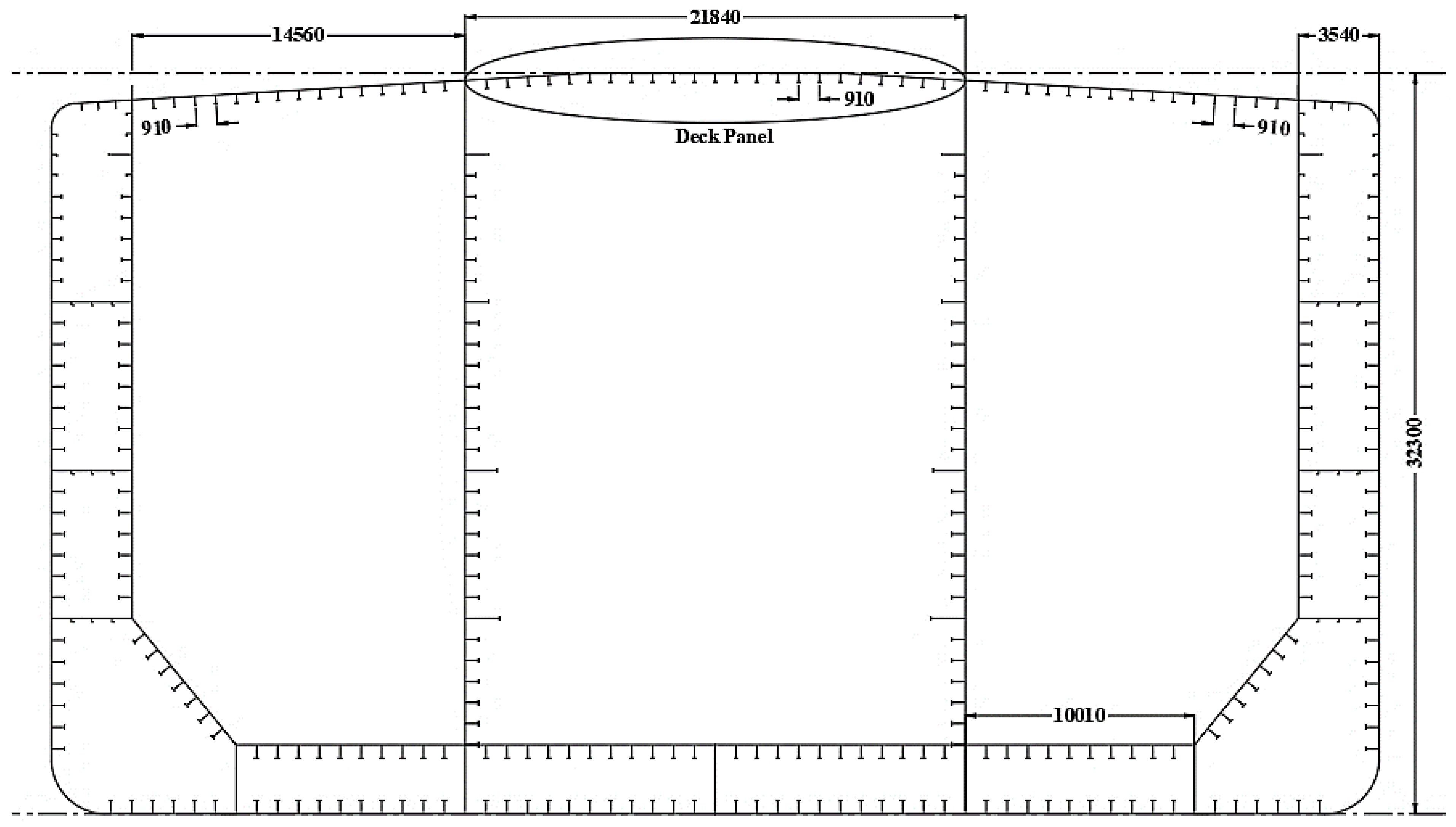
Figure 2.
Profile of deck panel with T-stiffeners (scale not depicted).
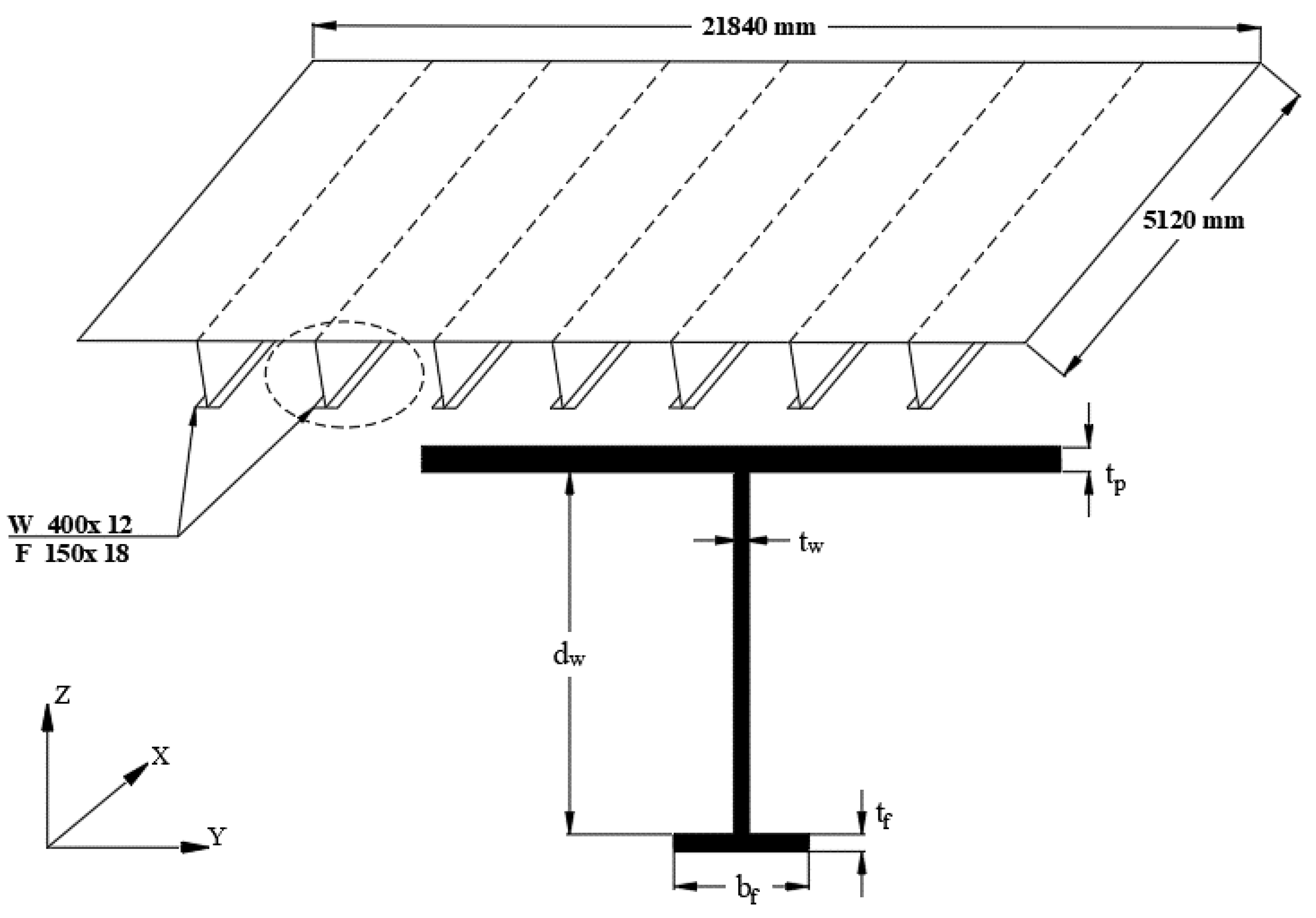
Figure 3.
Geometric characteristics of the analysed sandwich panel.

Figure 4.
Flow chart of the applied procedures for NLFEA Calculations.
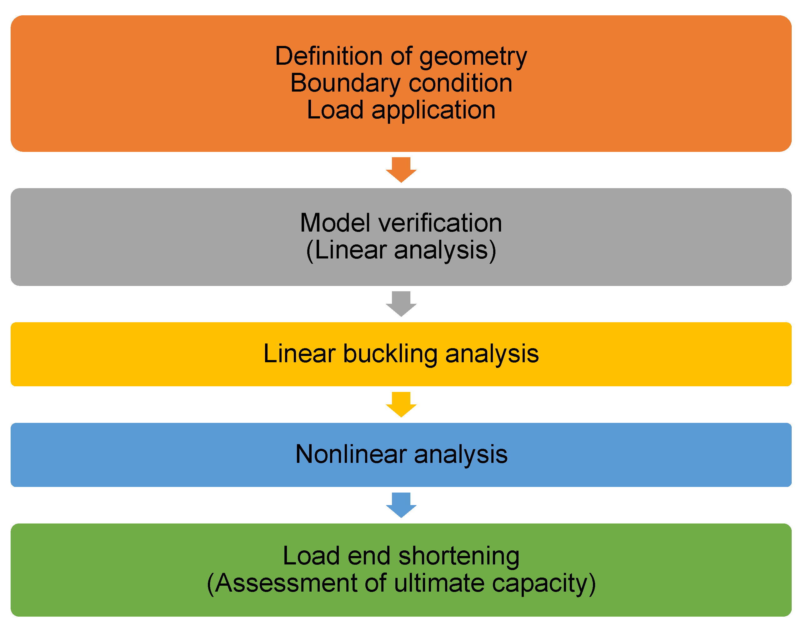
Figure 5.
Idealized elastic perfectly plastic stress–strain curve.
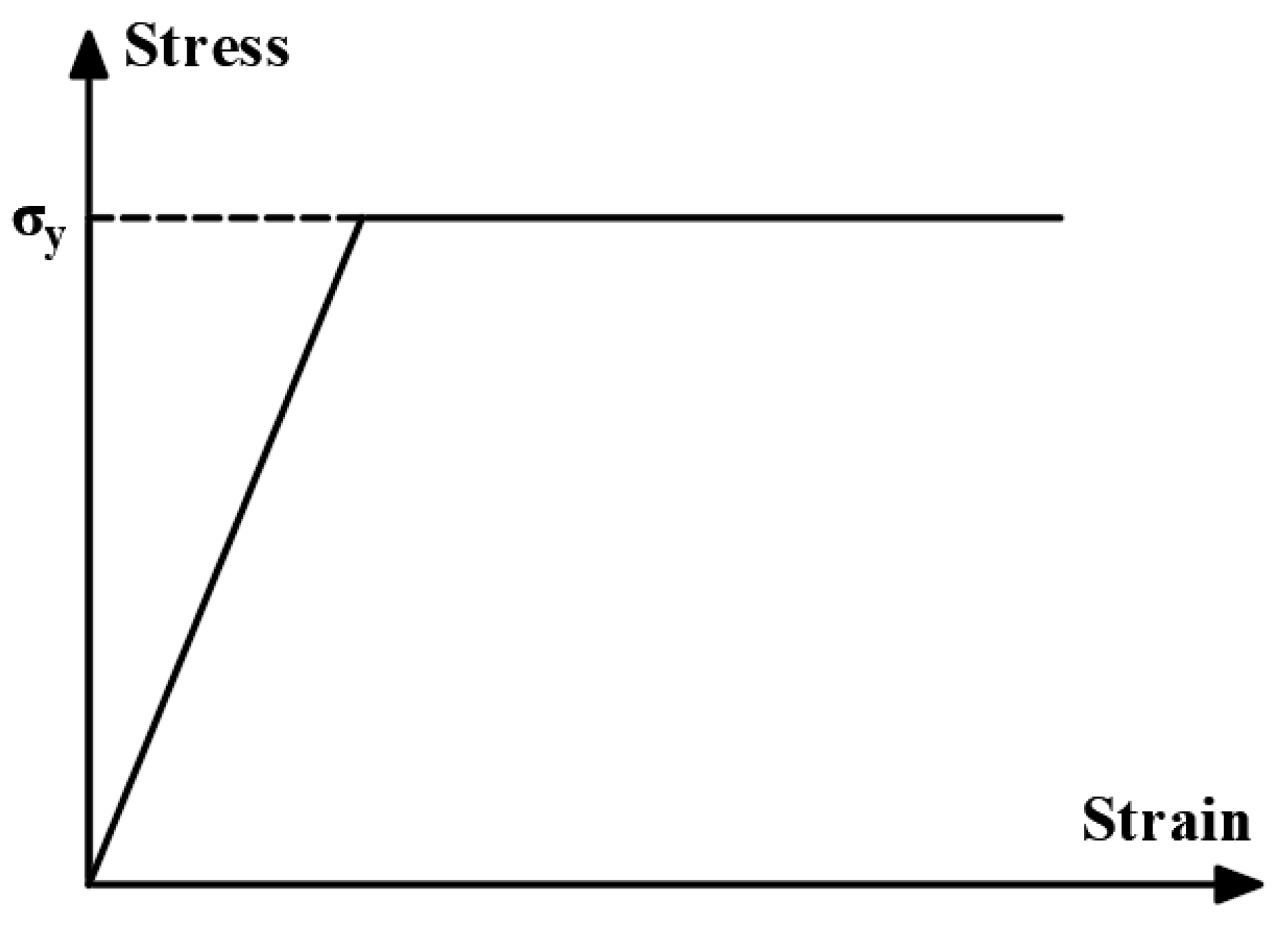
Figure 6.
Boundary conditions and loading.

Figure 7.
Local deflection of the face plates. (a) Symmetric local deflection. (b) Asymmetric local deflection.
Figure 7.
Local deflection of the face plates. (a) Symmetric local deflection. (b) Asymmetric local deflection.
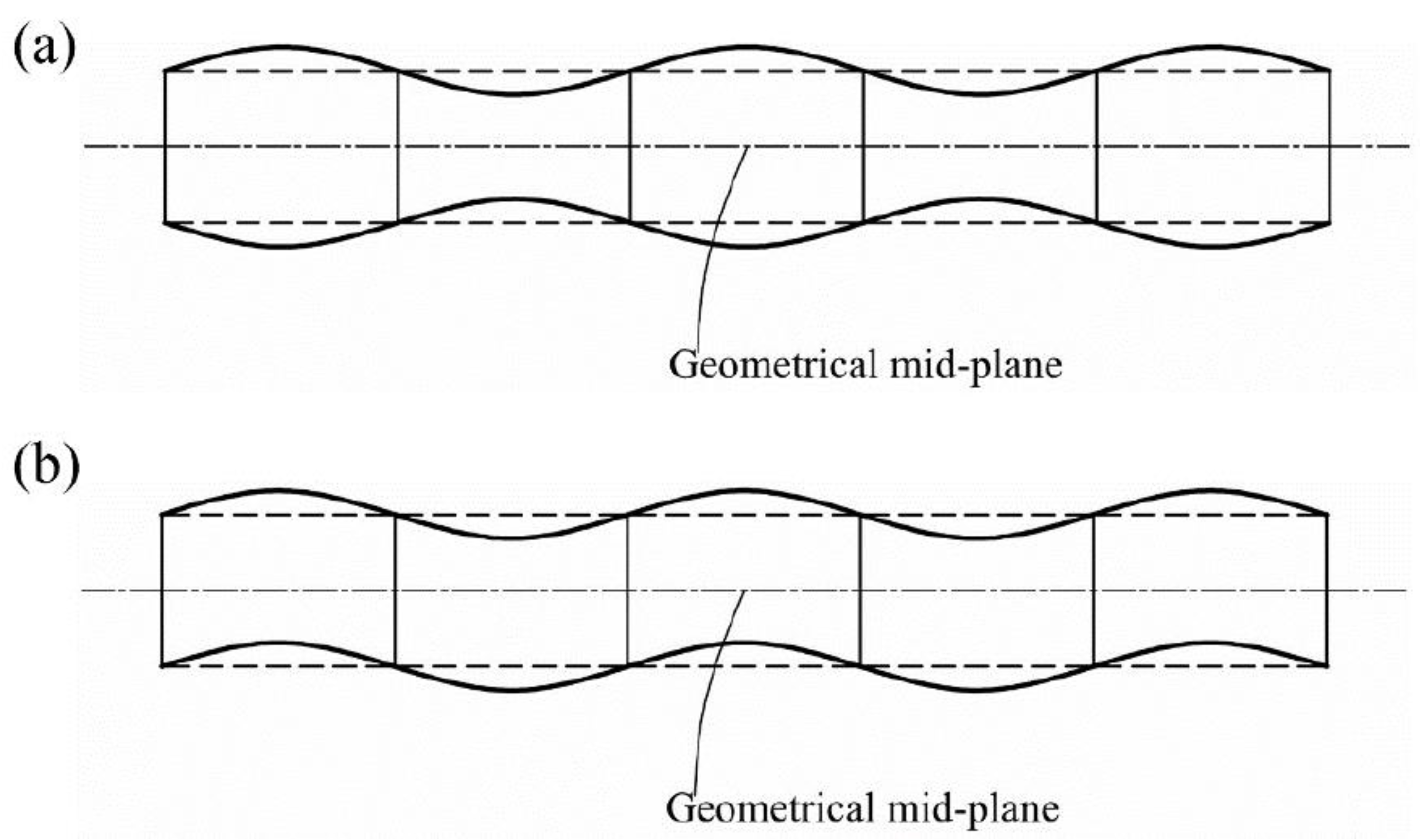
Figure 8.
Normalized stress–strain curves of the present NLFEA results and Khan and Zhang [45].
Figure 8.
Normalized stress–strain curves of the present NLFEA results and Khan and Zhang [45].

Figure 9.
The calculated ULS results for all scenarios of sandwich panels using the ANSYS non-linear finite element method (different colours for the various combinations of web spaces and height web).
Figure 9.
The calculated ULS results for all scenarios of sandwich panels using the ANSYS non-linear finite element method (different colours for the various combinations of web spaces and height web).

Figure 10.
Flowchart for the optimization process using RSM.

Figure 11.
Local sensitivity of structural parameters.
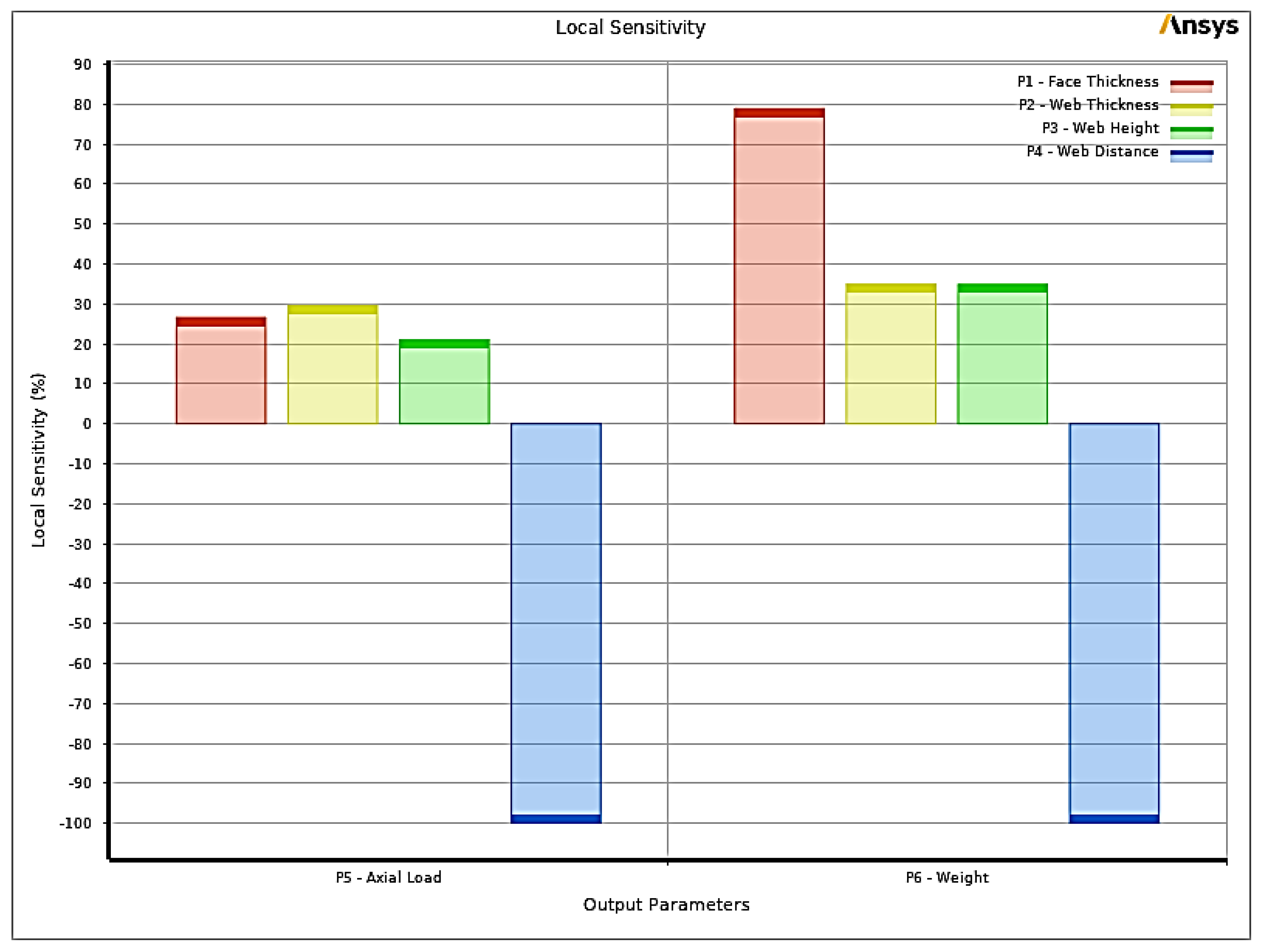
Figure 12.
The response surface depicting the ultimate axial load concerning variations in the input parameters, where: (a) face thickness vs. web thickness; (b) face thickness vs. web height; (c) face thickness vs. web spacing; (d) web thickness vs. web height; (e) web thickness vs. web spacing; (f) web height vs. web spacing.
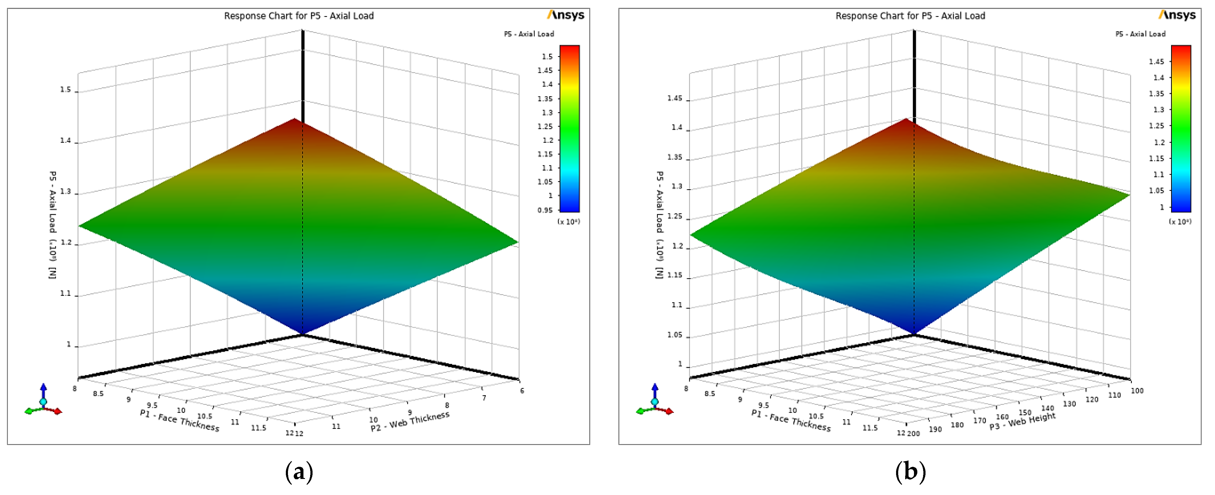

Figure 13.
Compressive load (N) vs. displacement (mm) curve for conventional panel and optimum sandwich panel.
Figure 13.
Compressive load (N) vs. displacement (mm) curve for conventional panel and optimum sandwich panel.

Table 1.
Principal dimensions of the object ship.
| Parameter | Value |
|---|---|
| Ship length overall (m) | 332 |
| Ship length between perpendicular (m) | 320 |
| Ship breadth (m) | 58 |
| Ship depth (m) | 31 |
| Design draft (m) | 20.8 |
| Displacement at design draft (ton) | 341,000 |
Table 2.
Material main characteristics of Steel Grade A.
| Density | Young’s Modulus | Poisson’s Ratio | Yield Stress | Strain Hardening |
|---|---|---|---|---|
| kg/m3 | E (MPa) | ν | σy (MPa) | Et/E |
| 7800 | 206,000 | 0.3 | 315 | 0 |
Table 3.
Geometric characteristics of the stiffened panel under examination in the validation study.
Table 3.
Geometric characteristics of the stiffened panel under examination in the validation study.
| L (mm) | Bp (mm) | s (mm) | N | tp (mm) | dw (mm) | tw (mm) | bf (mm) | tf (mm) |
|---|---|---|---|---|---|---|---|---|
| 4300 | 4075 | 815 | 4 | 17 | 463 | 8 | 172 | 17 |
Table 4.
Response surface optimization candidate points.
| Input Parameters | Output Parameters | |||||
|---|---|---|---|---|---|---|
| tf (mm) | tw (mm) | hc (mm) | S (mm) | Ultimate Load (N) | Weight (ton) | |
| Candidate Point 1 | 8.0321 | 7.9796 | 100.88 | 177.61 | 1.18 × 10⁸ | 18.092 |
| Candidate Point 2 | 8.0686 | 7.5898 | 102.48 | 174.91 | 1.18 × 10⁸ | 18.089 |
| Candidate Point 3 | 8.0171 | 7.273 | 108.69 | 174.21 | 1.18 × 10⁸ | 18.1 |
Disclaimer/Publisher’s Note: The statements, opinions and data contained in all publications are solely those of the individual author(s) and contributor(s) and not of MDPI and/or the editor(s). MDPI and/or the editor(s) disclaim responsibility for any injury to people or property resulting from any ideas, methods, instructions or products referred to in the content. |
© 2023 by the authors. Licensee MDPI, Basel, Switzerland. This article is an open access article distributed under the terms and conditions of the Creative Commons Attribution (CC BY) license (https://creativecommons.org/licenses/by/4.0/).
Share and Cite
MDPI and ACS Style
Elsaka, M.; Guedes Soares, C. Ultimate Strength Behaviour and Optimization of Laser-Welded Web-Core Sandwich Panels under In-Plane Compression. J. Mar. Sci. Eng. 2023, 11, 2200. https://doi.org/10.3390/jmse11112200
AMA Style
Elsaka M, Guedes Soares C. Ultimate Strength Behaviour and Optimization of Laser-Welded Web-Core Sandwich Panels under In-Plane Compression. Journal of Marine Science and Engineering. 2023; 11(11):2200. https://doi.org/10.3390/jmse11112200
Chicago/Turabian StyleElsaka, Mohamed, and C. Guedes Soares. 2023. "Ultimate Strength Behaviour and Optimization of Laser-Welded Web-Core Sandwich Panels under In-Plane Compression" Journal of Marine Science and Engineering 11, no. 11: 2200. https://doi.org/10.3390/jmse11112200
Note that from the first issue of 2016, this journal uses article numbers instead of page numbers. See further details here.