Article

Modeling Storm Surge and Inundation in Washington, DC, during Hurricane Isabel and the 1936 Potomac River Great Flood

1
Department of Physical Sciences, Virginia Institute of Marine Science, College of William and Mary P.O. Box 1375, Gloucester Point, VA 23062, USA
2
Noblis Inc., 3150 Fairview Park Drive South, Falls Church, VA 22042, USA
*
Author to whom correspondence should be addressed.
J. Mar. Sci. Eng. 2015, 3(3), 607-629; https://doi.org/10.3390/jmse3030607
Submission received: 3 April 2015 / Revised: 3 April 2015 / Accepted: 1 July 2015 / Published: 21 July 2015
(This article belongs to the Special Issue Coastal Hazards Related to Storm Surge)

Abstract

:
Washington, DC, the capital of the U.S., is located along the Upper Tidal Potomac River, where a reliable operational model is needed for making predictions of storm surge and river-induced flooding. We set up a finite volume model using a semi-implicit, Eulerian-Lagrangian scheme on a base grid (200 m) and a special feature of sub-grids (10 m), sourced with high-resolution LiDAR data and bathymetry surveys. The model domain starts at the fall line and extends 120 km downstream to Colonial Beach, VA. The model was used to simulate storm tides during the 2003 Hurricane Isabel. The water level measuring 3.1 m reached the upper tidal river in the vicinity of Washington during the peak of the storm, followed by second and third flood peaks two and four days later, resulting from river flooding coming downstream after heavy precipitation in the watershed. The modeled water level and timing were accurate in matching with the verified peak observations within 9 cm and 3 cm, and with R2 equal to 0.93 and 0.98 at the Wisconsin Avenue and Washington gauges, respectively. A simulation was also conducted for reconstructing the historical 1936 Potomac River Great Flood that inundated downtown. It was identified that the flood water, with a velocity exceeding 2.7 m/s in the downstream of Roosevelt Island, pinched through the bank northwest of East Potomac Park near DC. The modeled maximum inundation extents revealed a crescent-shaped flooding area, which was consistent with the historical surveyed flood map of the event.

1. Introduction

The subject of storm surge and inundation has long attracted physical oceanographer and coastal engineers, because these hazards can inflict tremendous damages and cause enormous impacts on human life and property. It thus becomes the most pressing issue to the coastal community as to how to minimize the impacts from storm surge and inundation during extreme weather conditions. The early studies focused on constructing the proper formulation on the structured grid for storm surge [1,2,3,4]. Recently, a breed of unstructured grid models coupled with the wind wave models became available and were applied in a relatively large domain [5,6,7]. For sub-grid modeling, the sub-grid scale parameterization was used for modeling inundation in a relatively small urban area (4 km2) [8] and LiDAR (light detection and ranging) data was applied to study the effect of distributed roughness on flows in the flood plain [9]. Wang et al. (2014) [10] successfully used the semi-implicit formulation combined with sub-grids in simulating inundation in the New York City during Hurricane Sandy.
In the coastal areas of the U.S. eastern seaboard, many cities are located at the fall line near the headwaters of an estuary, where river flow combined with storm surges can present a flooding hazard. During the 2003 Hurricane Isabel in Washington, DC, a storm surge of 8.8 feet (2.7 m) above mean sea level was recorded by the USGS (U.S. Geological Survey) gauge at Wisconsin Avenue and 10.1 feet (3.1 m) by a NOAA gauge on a pier in the Washington waterfront at the southwest portion of DC. Both observations, surpassed the previous records set by the 1933 Chesapeake Potomac Hurricane. After Isabel passed, the Potomac River crests reached DC two and four days later, as a result of the precipitation deluge in the Upper Potomac River Basin. In 1936, a flooding event affected much of the northeastern United States, ranging from the Ohio River Valley, New England south to the Potomac River Basin, as a result of a combination of heavy rain and snowmelt. At Washington, DC, the result was the 1936 Potomac River Great Flood. Damage was considerable along the Chesapeake and Ohio Canal, Harpers Ferry, WV, to Hancock, MD, with significant flooding in Washington, DC (USGS, 1937) [11]. The average daily flow on 18 March 1936 during the Potomac River Great Flood in Washington, DC was observed to be 12,100 m3/s, which was 39-times the normal daily flow, and water levels of 8.5 m and 5.7 m were observed at the Chain Bridge and at the Key Bridge (3.2 km apart), respectively [11]. In the Upper Potomac River, the flow passes through the fall-line as a fluvial river, transitions into a tidal river and eventually becomes a major estuary downstream. In the process, the direction of currents, flow pattern, frictional resistance, the geomorphology and the sediment characteristics are all subject to change as the flow regimes change. Works have been attempted to make predictions in the region for the combined storm surge and riverine flooding, but with shortcomings or limited success. The USGS has developed a hydrodynamic model for simulating unsteady flow in a network of open channels and implemented the model for the tidal Potomac River [12]. The effect of freshwater inflow, tidal currents and meteorological conditions were tested, but have not been applied for storm conditions. Recently, Mashriqui et al. (2010) [13] initiated the CERIS (Coastal, Estuary, River Information Services) system to provide an integrated suite of water information for hazard mitigation, water resources and ecosystem management. The unsteady HEC-RAS (Hydrologic Engineering Centers River Analysis System) model was developed and tested for a 2003 Hurricane Isabel simulation, but the phase lagged by 4–6 h and the peak elevation under-predicted by 30–50 cm when compared with the observations measured at NOAA’s Washington, DC, waterfront station. The National Weather Service’s (NWS) Advance Hydrologic Prediction Service was responsible for the forecast of the river discharge into the Upper Tidal Potomac River, but with a disclaimer that their forecasts do not include the wind-induced storm surge. Lastly, EA Engineering, Inc. of Hunt Valley, MD (2001) [14] applied RMA2, RMA4 and SED2D, a suite of finite element hydrodynamic, transport, and sediment models developed by Army Corps of Engineers, in the upper reach of the Potomac River only for the dye-tracer and turbidity plume studies.
In the present paper, we focus on producing high resolution street-level scale inundation by using sub-grids from DEM (Digital Elevation Model) nested within the base grid cell to allow fine-scale topography features to be modeled without a heavy computational cost. The primary objective is to predict the water level and inundation caused by various storm conditions occurred in the Upper Tidal Potomac River near Washington, DC. They can be the combination of the storm tide coming upstream from the bay and river flooding originated in the Upper Potomac River basin. Section 2 provides an overview of the study area, including observation stations. Section 3 describes a sub-grid model incorporating LiDAR and high-resolution bathymetry data into a regular base grid and solved by a non-linear solver. Section 4 depicts the setup and modeling results of the 2003 Hurricane Isabel. Section 5 describes the modeling of 1936 Potomac River Great Flood during which the floodwater breached through Potomac bank and inundated downtown DC. Section 6 discusses outstanding issues and concludes the paper.

2. Study Area

Washington, DC, is the capital city of the United States and a major metropolitan area with a population of 5.8 million, including its surrounding suburban areas. It is located near the head of the Upper Tidal Potomac River (Figure 1, right panel) where the river flows across the fall line and meets the tide from the Chesapeake Bay. The Potomac River is the largest tributary of the Chesapeake Bay, whose length from the fall line to the mouth at Point Lookout is about 180 km. The Potomac River is like many other rivers along the Atlantic seaboard that has its hydraulic head in the Appalachian Mountains and flows eastward to the Atlantic Ocean. As it flows over the fall line, Potomac creates a spectacular landscape feature: the Great Falls. From the Great Falls to Theodore Roosevelt Island, the river goes through a series of rapids, narrow rock-girded channels twisting between cliffs, flow-topped bedrock and numerous islands composed of sand and gravel laid down by the river. The river transitions into the tidal portion of the river near the Chain Bridge, a few kilometers upstream from Roosevelt Island. The average flow is approximately 320 m3/s; the flow may be less than 40 m3/s in the summer and reaches 3800 m3/s during flood periods. The tide in the Potomac is an integral part of the Chesapeake Bay system; originating from the Atlantic Ocean and propagating upstream along the main stem of the bay into the Potomac River. It can reach up to the Chain Bridge, where the tidal influence ends. The mean tidal range at Wisconsin Avenue is approximately 0.9 m. The tidal phase lags 11.5 h behind that at Hampton Roads at the mouth of the Chesapeake Bay. The model grid was constructed from the Little Falls (USGS Station 01646500; latitude 38°56′59.2′′ longitude 77°07′39.5′′), MD, at the fall line to Colonial Beach, VA, with a total length of about 120 km, as shown in Figure 2a. The domain covers about 2/3 of the tidal Potomac River area and contains a total of 18,259 base grids in square elements with a resolution of 200 m × 200 m and incorporates sub-grids (the sub-grids will be described in detail in Section 3). The bathymetry and topography associated with the model domain ranging from −10 m to 10 m (minus represents above ground) are displayed in Figure 2b. The observation stations used for the study include Little Falls, MD (USGS), Wisconsin Avenue (USGS), Washington, DC, waterfront (NOAA), Colonial Beach, VA (NOAA), and Lewisetta, VA (NOAA), whose locations are marked by solid symbols shown in the left panel of Figure 1. Among these stations, Washington, DC, is one of the longest-serving tide stations in the nation, which started operation 15 April 1931. For this study, the mean sea level is used as the datum.
Figure 1. (Left) The Potomac River modeling domain (shaded) and observation stations used for the study; (right) the zoom-in map of Washington, DC, and the Upper Tidal Potomac River.
Jmse 03 00607 g001

3. Storm Surge and Inundation Model Incorporating Sub-Grids in the Upper Tidal Potomac River

3.1. Model Description

This study makes use of a robust semi-implicit finite difference/finite volume model UnTRIM2 (Unstructured Tidal Residual Intertidal Mudflat Model, power 2 version). The model is governed by the three-dimensional shallow-water equations with the Boussinesq approximation and is solved for free surface elevation, water velocities and salinity in a Cartesian coordinate system. The model was formulated with an efficient semi-implicit, Eulerian-Lagrangian scheme on unstructured orthogonal grids that includes both 3D barotropic and baroclinic processes pertaining to tide, wind and gravitationally-driven circulation on an f-plane [15,16,17]. The Potomac River is one of the major tributaries of the Chesapeake Bay, whose drainage area is 38,000 km2, and the mean annual mean river discharge is 360 m3/s. The Upper Tidal Potomac River is dominated by fresh water discharge, wind and tide. The tide from downstream can reach up to the Chain Bridge near DC, whereas the salt water intrusion normally only reaches up to the U.S. Route 301 Bridge near Colonial Beach. The length of the salt intrusion upstream from the lower Potomac River varies with the season depending on the magnitude of the freshwater discharge, but in general, the transition zone moves around Colonial Beach. The temperature-induced stratification is small because of the shallowness of the estuary. Thus, the region from the fall line to Colonial Beach, which was chosen as the model domain, can be reasonably considered as the vertically well-mixed tidal fresh zone with the downstream side ends in the transition zone. Because the interest of the present paper is focused on barotropic motions driven by the river, tide and wind-induced surge in the Upper Tidal Potomac River, using the vertically-averaged 2D version of the model (but including 2D temperature) for the domain chosen is thus appropriate.
Figure 2. (a) The Potomac River grid domain including land area around Washington, DC; (b) the combined bathymetry data (30-m resolution) and LiDAR-derived topography (10-m resolution) used.
Jmse 03 00607 g002
The sub-grids, in the form of raster DEM (a grid of squares) derived from LiDAR and high-resolution bathymetry, is nested within the base grid cell to allow the fine-scale topography features to be recognized. In the base grid and sub-grid framework, the core computation for solving the shallow water equations is performed on the base grid. Once the base grid finishes the calculations, the total flux on each edge of the base grid is then distributed to the individual sub-grid cells based on the analytic solution of the hydraulic conveyance approach. To illustrate the principle, it is sufficient to consider the following simplified 2D depth-averaged sub-grid momentum equation:
u j t + g ζ x + c f | | u j | | h = 0                 u j t + g ζ x + g | | u j | | Ω j = 0
Where Ω j =   g h j / c f is hydraulic conveyance, uj is sub-grid velocity, ϛ the surface elevation and cf is a dimension-less friction coefficient for which a formulation, such as Chezy’s or Manning’s, can be given.
For the validity of the equation, the inundation flow is considered to be frictionally dominated, so the advection term can be considered as the second order. Since the sub-grid formula is applied only one step at a time within each marching time step of the base grid, uj is not a function of time. From this, it follows that the equation can be rewritten as uj = Ωj ζ x. Assuming the pressure gradient is constant on each edge (but velocity, friction and depth are variable), it can be shown that the velocity of the individual sub-grid can be obtained by the base grid velocity times the ratio of the hydraulic conveyance of the sub-grid to that of base grid on each side of the grid edge, based on the following formula:
| | u j | |   =    Ω j     | | U | | Ω          with         | | U | | =     j = 1 J h j | | u j | | j = 1 J h j   and      Ω = j = 1 J h j Ω j j = 1 J h j
where (||uj||, Ωj) and (||U||, Ω) are the velocity and conveyance for the sub-grid and base grid, respectively, and J defines the total number of wet sub-grids within a base grid.
This means that the sub-grid velocity and its cross-section flux (the product of velocity and the cross-section area) at the edge of each of the sub-grid can be obtained analytically. Together with the bathymetry within each of the sub-grids, the water depth of each sub-grid and the status of its wetting (or drying) can be determined. Once the depth and the wetting and drying of the individual sub-grids are decided, the wetting, drying and/or partially-wetting-drying of the “base grid” can then be determined collectively by the distribution of the sub-grid population within that base grid. Here, it is important to recognize that the partially wetting-and-drying of the base grid, a desired feature for more accurately determining the inundation extent, which is unavailable by the traditional method, is now possible, attributed to the sub-grid approach. Another important aspect of the present approach is that sub-grid scale information does feed back to the base grid computation, one piece of which is the friction parameter. Now, the base grid friction is no longer dependent on the single gross-averaged depth on the base grid; rather, it is obtained as the collective contributions from each of the wet cells of the sub-grids according to the conveyance formulation above. One other important parameter, cross-sectional fluxes, essential to the base grid computations, are also based on the summation of the product of each sub-grid velocity times each sub-grid bathymetry, rather than the product of the averaged velocity and averaged cross-section area at the edge of the base grid. The accuracy of the cross-sectional calculation was further enhanced by using a nonlinear solver to determine the nonlinear relationship between water level and the cross-section area [18,19]. These combined approaches result in a more accurate determination of the cross-sectional flux, remove the requirement of using the minimum water depth (by the traditional models) and improve on the long wave propagation speed, which perhaps is crucial for determining the correct tidal phase. Computational-wise, all of this is done without having to resort to using a fine-scale computational mesh throughout the study area to compute the small-scale dynamic processes. The savings of computation time is thus quite significant.

3.2. Incorporation of LiDAR-Derived DEM into the Sub-Grid Model Domain
The horizontal computational domain comprises a set of non-overlapping convex three- or four-sided polygons. Each polygon side is designated as either a side of an adjacent polygon or as a boundary line in the model grid input file. The innovations in the UnTRIM model permit the use of a sub-grid mesh embedded within each base grid element with an inherent numerical scheme capable of partial wetting and drying [19]. Although the sub-grid can be implemented on either a triangular or rectangular grid, numerical accuracy is favorable when a uniform grid comprising quadrilaterals is used with high-resolution DEM (digital elevation model) sourced with LiDAR-derived data to best represent urban street-level flooding. The use of square grid structures has been demonstrated as a favorable method to preserve the city-block building structures with sufficient DEM resolution to resolve streets between buildings as an effective conduit for accurately modeling inundation [10,20]. For this reason, many of the grids developed using LiDAR-derived DEMs have been scaled to square grids congruent to the native pixel resolution of the topographic data contained in the DEM to avoid further interpolation. Using a square grid, the normal velocity on the faces of each polygon is calculated at the center point of the face, and the centers of two adjacent polygons are equally spaced from the shared face, which minimizes the associated discretization error in these computations. An unstructured, non-uniform grid can be utilized with a larger associated discretization error [21]. However, the benefits of mixing triangles and quadrilaterals to conform the grid shape to the bathymetric channels and shorelines are less significant with recent advancements, including the addition of sub-grids to the model, due to the partial wetting and drying scheme and the non-linear solver.
The setup and design of the model involves generating a base-grid mesh for which computations are geometrically calculated. The domain starts at Little Falls passing through the confluence of the Potomac and Anacostia Rivers and ends in Colonial Beach, VA. One more reason Colonial Beach was chosen is because it is a NOAA tidal station far downstream of DC. The Washington, DC, topography was a LiDAR-based DEM with 10-m resolution produced by Noblis with the NAD83 CORS 96 horizontal datum projected in UTM Zone 18N coordinates with a vertical datum of NAVD88 in meters. The topographic data were cast over a 200-m base grid with an embedded 20 × 20 10-m resolution sub-grid. This base grid resolution was chosen such that the main stem of the Potomac River channel would be multiple grid cells in width across the river for proper calculation of volume transport. The sub-grid scaling was chosen such that the topographic LiDAR-derived DEM would be at its native resolution (10 m) and not require further interpolation, which potentially could cause additional computational error due to stretching or distortion. Bathymetry point data (≈30-m point spacing) were retrieved from five NOAA bathymetric surveys of the Potomac and Anacostia Rivers conducted in 1974 (NOAA Surveys: H09477, H09380, H09479, H09488, H09478). Using a shoreline polyline in ArcGIS 10.3, a power 2 inverse distance weighted interpolation was performed on the bathymetry data using the shoreline polyline as a barrier. The resulting interpolation product was then translated to NAD83 CORS 96 in UTM Zone 18N with a vertical datum of NAVD88 in meters. With the two datasets in the same projection and datum, they were merged such that the bathymetric data would overlap the LiDAR topographic data to resolve issues with bridges in the LiDAR DEM potentially blocking proper fluid movement into creeks and shallow water regions. Inherent uncertainty in the vertical data from the LiDAR (1-cm precision with ±30-cm accuracy) and bathymetric datasets (10-cm precision with ±0.5-m accuracy) contributes directly to uncertainty in inundation thickness, while uncertainty in the spatial extents is amplified by the slope of the DEM at the wetting and drying interface.
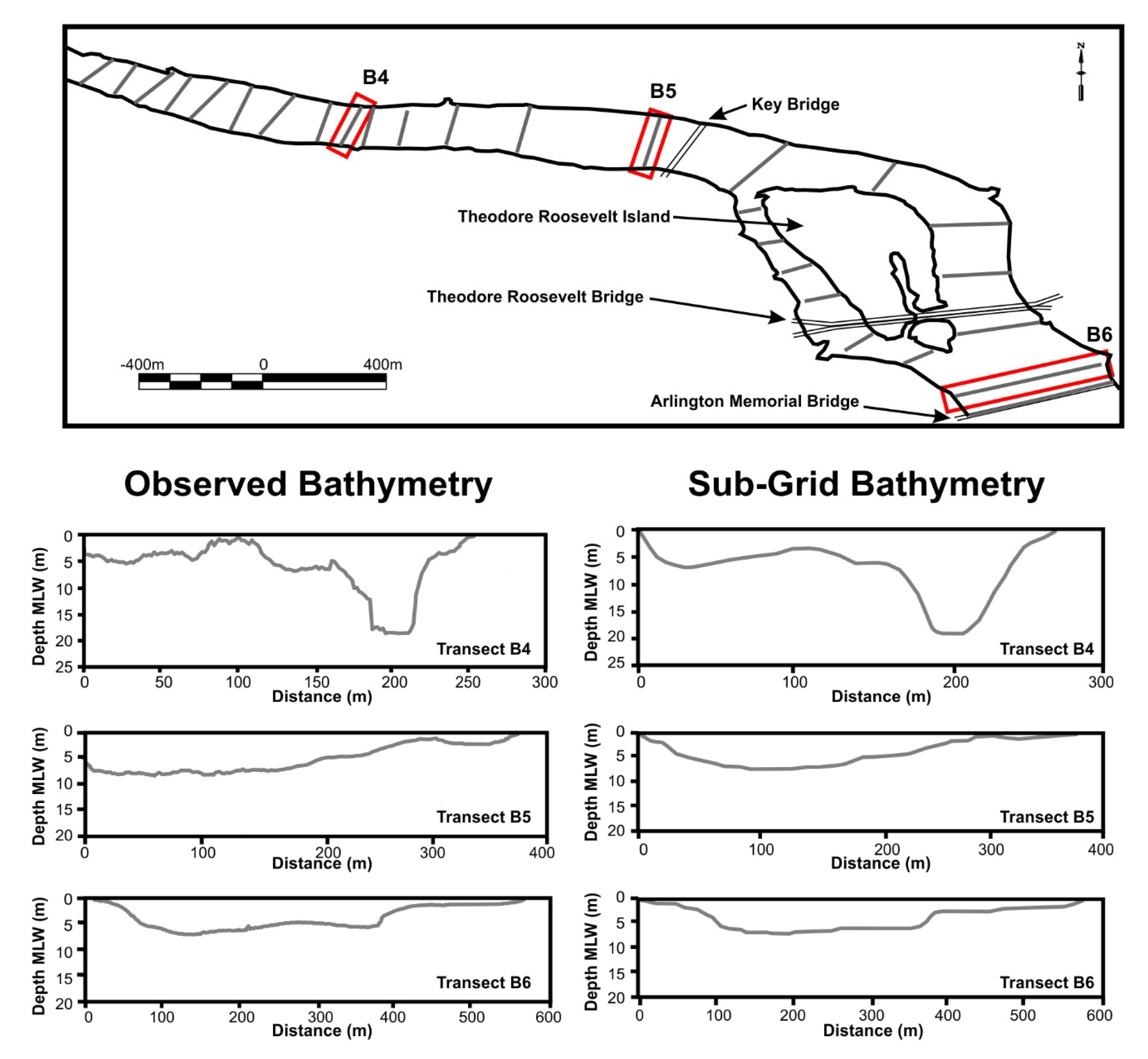
Spot checks of the combined DEM with known topography and bathymetry indicated reasonable agreement. The bathymetry data were subsequently verified with a report [14] submitted to U.S. Army Corps of Engineers Baltimore District, MD that provides transect data near Theodore Roosevelt Island and the Arlington Memorial Bridge (Figure 3). The resulting topography and bathymetry merged DEM was input to Janet v.2.2, an unstructured grid software by Smile Consulting Inc. (Hamburg, Germany), to provide elevations for the model base grid and sub-grid. Ultimately, the grid was constructed with a 200-m base grid with a 10-m resolution sub-grid for use in this study (Figure 4). The simulations for this modeling effort were performed on a Dell T3500 PC Workstation with Windows 7 Professional (64-bit edition) and an Intel Xeon Quad Core X5570 Processor (2.93GHz) (headquarter at Santa Clara, CA, USA) with 24 GB RAM. The performance efficiency of the CPU during these modeling simulations was approximately 120-times faster than real time.
Figure 3. Three example of bathymetric transects in the Upper Potomac River used to verify bathymetry interpolation, with corresponding sounding data published in EA Engineering (2001) [14] (bottom left) and the model’s sub-grid bathymetry (bottom right) in the vicinity of the Washington aqueduct.
Jmse 03 00607 g003
Figure 4. Detailed feature of the based grid vs. sub-grids in Washington, DC, near Roosevelt Island. The thicker white line shows the 200-m base grid with each grid cell containing a 20 × 20 of 10 m × 10 m sub-grid cells. The resolution is such that LiDAR data are in 10-m resolution and bathymetry in 30-m resolution. An example of the bathymetry cross-section is shown in the lower left corner.
Jmse 03 00607 g004

4. Modeling the 2003 Hurricane Isabel Event

The 2003 Hurricane Isabel was the most devastating hurricane to ravage the Chesapeake Bay in recent history. It made landfall on the Outer Banks of North Carolina on 18 September 2003 and was reduced from a Category 5 to a Category 2 storm on the Saffir-Simpson hurricane intensity scale immediately prior to making landfall. Still, the hurricane storm surge that propagated up the Tidal Potomac River to the Washington, DC, area resulted in 160 homes, 60 condominiums flooded and an additional 2000 units of buildings reporting severe damage in Fairfax County and the City of Alexandria. In Washington, DC, the storm peak height was recorded at the Wisconsin Avenue gauge as 3.4 m and at the Washington, DC, gauge as 3.1 m. Heavy rainfall was reported in the Upper Potomac River Basin, peaking at 510 mm (20.2 inches) in Sherando, VA, which resulted in a peak discharge rate 4000–4500 m3/s recorded at the USGS Little Falls, MD, station at the fall line.

4.1. Model Setup

Modeling the 2003 Hurricane Isabel event required two boundary conditions. One is the upstream river discharge boundary conditions specified at the Little Falls, MD, and the other is the water level open boundary condition specified at Colonial Beach, VA, 120 km downstream. The river discharge data provided were daily discharge, and the water level data provided at the downstream open boundary condition were every 6 min. The headwater of the Potomac River near the upstream boundary condition has spectacular landscape features. It cascades over a series of 20-foot (6 m) falls, falling a total of 76 feet (23 m) in elevation, with rapids, narrow rock-grid channels, twisted cliffs and flow-topped bedrock islands until reaching Chain Bridge. In addition, the Potomac narrows significantly as it passes through falls and the Mather Gorge, and the nearby shoreline can be inundated by floods caused by heavy rain or snow from the watershed upstream. Given these complex features, there is a question as to how to properly assign the upstream boundary condition. Written in terms of open channel non-uniform flows [22], the governing equation can be expressed as:
    d H d x =   d d x     ( z + y +   u 2 g )   =     S f
d d x ( y +   u 2 g ) =     d z d x     S f                       d E d x =   d z d x     S f
where H is total energy; E is the specific energy; y is the vertical depth of flow above the channel bed; z is the height above the datum of the bed level; Sf is the friction slope.
According to the equations above, it can be deduced that, with a given bathymetry, the non-uniform flows are controlled by the external inputs of the water level and momentum, as well as the dissipation by the internal friction slope. Two types of boundary conditions were considered: (1) the horizontal flux boundary condition, for which the horizontal volume flux is specified as the product of horizontal velocity times the cross-section; and (2) the vertical volume flux given as a point source with which there is no horizontal momentum. Type 1 takes total discharge and represents it in the form of horizontal kinetic energy as the specific energy, whereas Type 2 takes total discharge and represents it in the form of the accumulation of vertical volume flux, which manifests as the elevated free surface equivalent to a form of potential energy in specific energy. For the Upper Tidal Potomac River, the water level and velocity downstream depend on how the specific energy is specified at the upstream boundary plus the internal dissipation by the friction slope. The internal dissipation induced by the Great Falls in the Potomac River is a complicated phenomenon, and the dynamics is not known, a priori. In our test, the Type 1 boundary condition was used at first, and it was found that the result during high flow was unsatisfactory (not shown). After several sensitivity tests, we found that dividing the total flow 50% for Type 1 combined with 50% for Type 2 performs the best, as shown in Figure 5, and so, this was used. It is conjectured that the reason that these divisions are needed may have to do with the presence of falls and rapids. After all, using the weighting between the momentum flux and point source is not the most rigorous approach we would like to have used; nevertheless, with the sensitivity test, it does suggest that with the presence of falls and rapids in a river, the conventional horizontal momentum inputs at the head of the river may not be the best boundary conditions to use.
The gauge at Colonial Beach, VA, was functioning during the period prior to the peak of the hurricane event, which destroyed the gauge platform. Thus, a portion of the time series of the water elevation was selected from another Potomac River station at Lewisetta, VA, about 60 km downstream from Colonial Beach (refer Figure 1). The water level of the two stations between Colonial Beach, VA, and Lewisetta, VA, is well correlated, and the tidal phase required a phase shift of 45 min. The friction coefficient, Manning’s “n”, was used to calculate the bottom shear stress, and the “n” value was obtained by comparing with the independent astronomical tide prediction dataset provided by the NOAA Tides and Currents website for 15 stations. Tests were conducted, including the comparison of modeled mean tidal range and the time of high water to the observations. With the sub-grid feature and nonlinear solver used, it was found that standard Manning’s n = 0.025 works adequately for the domain from Colonial Beach, VA, up to the Washington, DC, station. However, from the Washington, DC, station to the upper reaches near the headwaters from Little Falls, MD, required a coefficient of n = 0.040 to produce the best results. This is expected because the headwaters are in a fluvial river environment, which can exert extra shear stress on the passing flow. The wind and atmospheric pressure data were retrieved from NOAA observation data at Washington, DC (Station No. 8594900). These data were interpolated to 5-min intervals of the model time step for the same time period and prepared as a uniform input throughout the domain for Hurricane Isabel. The Garratt (1977) wind drag formula [23] was used to calculate the wind stress with a cap on drag coefficient at U10 (at 10 m height) for wind speed greater than 40 m/s [24]. Model simulations began on 00:00 GMT 1 September 2003 and ended at 00:00 GMT 1 October 2003 with a five-day spin up period.

4.2. Results

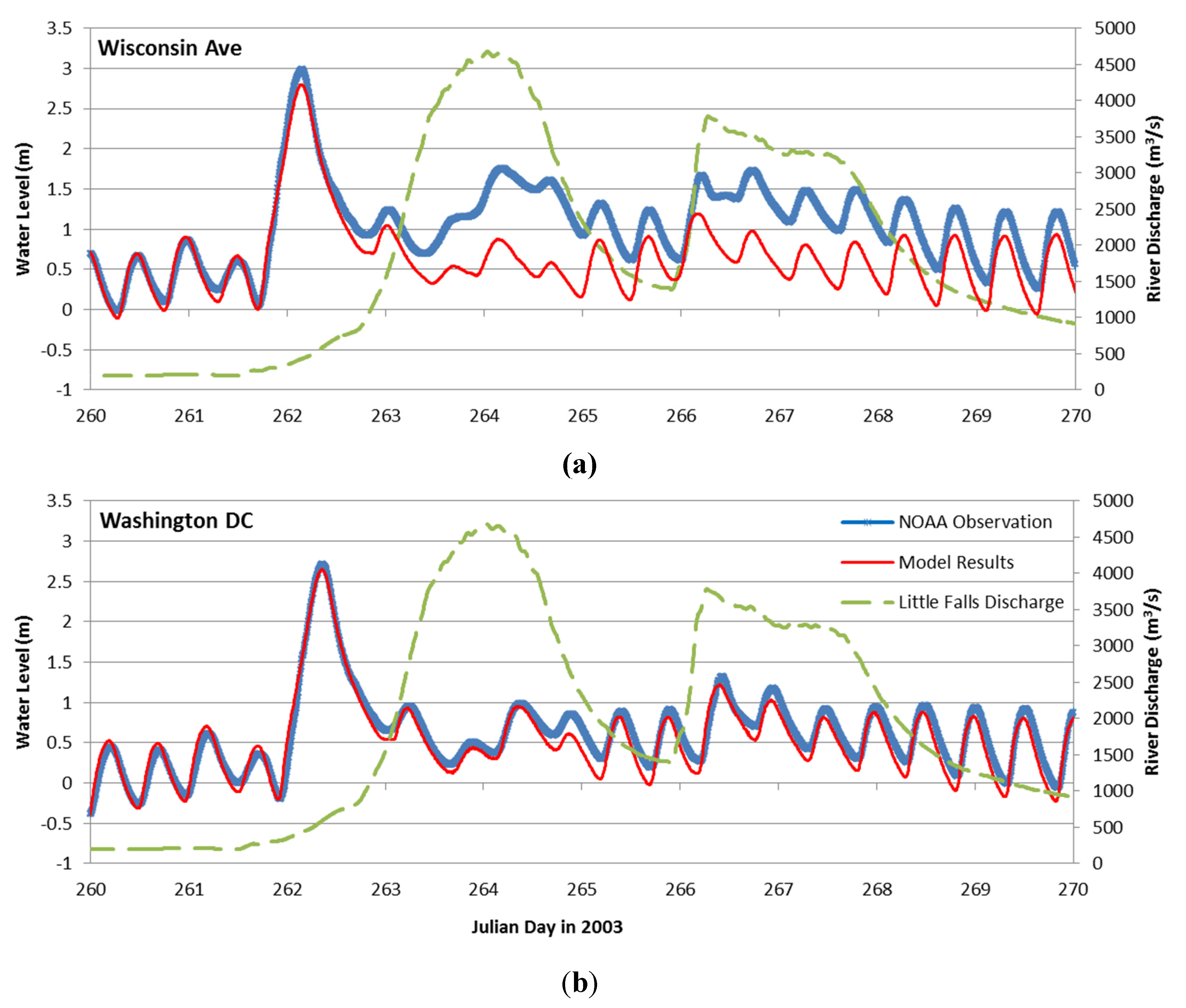
The modeled water level compared with observations at Wisconsin Avenue and at Washington, DC, is shown in Figure 5a,b. The statistical measures of the water level comparisons in terms of R2 (R-squared value), RMS (root mean square) and peak difference were 0.94, 14.3 cm and 9.2 cm for Wisconsin Avenue and 0.98, 7.3 cm and 2.4 cm for Washington, DC, respectively, as shown in Table 1. For a hurricane event with the peak water level reaching 3 m, the prediction skill of the current model is quite reasonable. In further analysis of the individual uncertainties over the comparisons, the largest uncertainties, based on NOAA Co-OPS’s user manual, were associated with the seasonal effect of the tidal river, local wind and weather patterns and thermal expansion. The errors can also be associated with the datum selected (1–5 cm) and the measurement technique (1–2 cm). In our effort in simulating storm tide of the 2003 Hurricane Isabel, the observed wind, pressure, river discharge and temperature fields were prescribed to the model; thus, seasonal effects were not be a major issue for the uncertainty. There were still base errors, which were embedded in the datum selection and the measurement itself, which amounts to about 2–7 cm. Our water level prediction at the Washington, DC, station was close to this lower limit.
Table 1. Statistical comparison of modeled time series vs. observations during Hurricane Isabel.
StatisticWisconsin Ave.Washington, DC
R²0.940.98
RMS14.3 cm7.3 cm
MAE11.4 cm4.8 cm
Peak Difference9.2 cm2.4 cm
From Figure 5a,b, it was noted that the hurricane-induced storm surge peak, which was characterized by a single peak at a height close to 3 m, arrived first on Julian Day 262.5 immediately after the hurricane made landfall. This first peak was followed by the gentler second and third flood peaks on Julian Days 264.5 and 266.5, respectively. Examination of water level variation and the Little Falls river discharge curves together showed that the second and third peaks were associated with the river floods of two peak flows: 4500 m3/s and 4000 m3/s. These two peak flows did not arrive until two and four days after the Hurricane passed, an indication of the delay of the watershed in collecting the precipitation dumped by the hurricane. To test the hypothesis quantitatively that the second and third peak were indeed the river discharge induced, a sensitivity tests was conducted with a scenario in which the no flux boundary condition was assigned at the head of the river. The scenario was dubbed “without” river discharge. The model results, under “without” river discharge, under-predicted the observed water level (along with the “with” river discharge model results) during the high flow period by about 1 m for the second peak and about 0.5 m for the third peak at Wisconsin Avenue station, as shown in Figure 6a. The under-prediction of water level during high flow periods was obvious at the Wisconsin Avenue station; however, it was not as clear at the Washington, DC, station.
Figure 5. The 2003 Hurricane Isabel model simulation results for (a) Wisconsin Avenue and (b) for Washington, DC, compared with the gauge measurement. Model results are shown in red and observation in blue; also included is the Potomac River discharge at Little Falls, MD, shown in green (with the scale on the right-hand side scale).
Jmse 03 00607 g005
Figure 6. The 2003 Hurricane Isabel model simulation results for (a) Wisconsin Avenue and (b) for Washington, DC, similar to Figure 5, except using zero upstream river discharge at Little Falls, MD. Although not used as an upstream boundary condition, the Potomac River discharge (in green) at Little Falls, MD, was retained for reference.
Jmse 03 00607 g006
With a close examination of the results presented in Figure 5b and Figure 6b at the Washington, DC, station, it was found that the “without” river discharge scenario resulted in a decreasing water level by only 0.2 m and 0.1 m for the second and third peak, respectively, at the Washington, DC, station when the “with” and “without” river discharge scenarios were compared. This was approximately one fifth of the water elevation under-prediction occurring at Wisconsin Avenue. Our explanation regarding the fact that the same high river floods have less influence on the water level at that Washington, DC, station than that of the station at Wisconsin Avenue was attributed to the following two factors: (1) significant widening of the Potomac River channel downstream of Roosevelt Island; the width at the confluence of Potomac and Anacostia is 3.5-times that near Wisconsin Avenue; and (2) expansion of the flood plains during floods. The Potomac River downstream of Roosevelt Island, including the Tidal Basin, Washington Channel, East Potomac Park, Virginia Park and Reagan Airfield, is a vast area of low lying lands with channels and land intertwined. The region acts like a major floodplain during the floods and can assimilate a large volume of river discharge by expanding the inundation region in several directions horizontally. The extent of the inundated area during the 1936 Potomac Great Flood can be found later in section 5.2, which showed the vast expansion of flood zone downstream of the Roosevelt Island.
A spatial inundation map for the flooding associated with Hurricane Isabel was also generated at the City of Alexandria, where a substantial area of the docks and business district along the waterfront of the Potomac River experienced extensive flooding, as shown in Figure 7. There is no official gauge measurement available in the region for a rigorous verification, but a picture taken by a citizen observer at the King Street and Union Street intersection right after the storm, as shown in the upper left corner, provided an interesting validation. It is visible and can be identified in the picture that the water marks reach 10.2 feet at the wall (marked by the red line). After examining the wrack line from several pictures taken at the same location, but at different times, we came to the conclusion that the water level was between 4 and 6 feet (1.2 m–1.8 m) above the ground during the peak height of the flooding, which was consistent with the model-produced peak inundation of 4.9–6.6 feet (1.5–2.0 m) at the site. Similar results were reported by Stamey et al. (2007) [25].
Figure 7. The modeled 2003 Hurricane Isabel-induced inundation in the City of Alexandria, VA. The photograph depicts a high water mark at the intersection of King Street and Union Street showing that the floodwater reached 10.2 feet, approximately 5.5 feet (1.7 m) above the ground level, which is consistent with the modeled inundation at the location, which is between 4.9 and 6.6 feet (1.5–2.0 m).
Jmse 03 00607 g007

5. Inundation Simulation for the Potomac River Great Flood of 1936

In March 1936, a combination of warmer-than-normal temperatures and torrential rain after a cold and snowy winter resulted in rapid melting of snow and rainfall runoff in much of the northeastern US, triggering the historic 1936 Great Flood. The result was significant flooding in much of the northeastern region of United States, ranging from the Ohio River Valley, New England and south to Washington, DC in the Potomac River Basin, prompting to the passage of Flood Control Act of 1936 by the Congress [26]. The damage was considerable along the Potomac River, ranging from Harpers Ferry, WV, to Hancock, MD, with significant flooding at Washington, DC. The water level height recorded at four miles (6.4 km) above Chain Bridge was 8.75 m, while at the NOAA station in Washington, DC was 5.70 m [27]. The peak river discharge during the Great Flood in Washington, DC, was observed to be 14,500 m3/s, which is 39-times of the normal daily flow.

5.1. Model Setup

To drive the inundation model, hourly discharge data obtained from the USGS station at Little Falls, MD, were used. Since only the hourly tidal water level at the Washington, DC, gauge station was available at the time of the flood in the Tidal Potomac River, the downstream open boundary condition was established by using the time series of water level measured at the Washington, DC, gauge station and extrapolating downstream to Colonia Beach, VA, by adjusting the tidal phase by 360 min advance in time. The Great Falls of the Potomac River mark the geological boundary whereby the elevation of the water rapidly changes, and thus, the boundary condition should account for both the kinetic and potential energy. The friction parameters used are obtained from the calibration over an independent astronomical tide dataset. Both the boundary condition and the selection of friction parameter were described in Section 4.1. The simulation period was 00:00 GMT March 01 to 00:00 GMT 31 March 1936. The 20 days simulation including a five-day spin up took about 4 h of real time in a seven processor PC to finish.

5.2. Results

For the illustration of the 1936 Potomac Great Flood results, it should be noted that, only the Washington, DC station had measurement data at the time. The station locations selected for time series comparison are two: the present day USGS Wisconsin Avenue station and the long-term Washington, DC waterfront station. The modeled water level from 10 March through 25 March of 1936 were shown for 15 days’ simulation in Figure 8a,b. In order to demonstrate the sub-grid modeling capability, two types of model results were presented—“With” the sub-gird (shown in red) and “without” the sub-grid (shown in gray). For “without sub-grid”, the grid used is a 200 m × 200 m base grid, and the topography is the average of the bare ground over the grid size. The green line superposed on the model results was the observed river discharge obtained from USGS Little Falls, MD, with a unit of m3/s using the scale on the right-hand side.
From the time series, one can observe two major temporal variabilities of the water level: one is a low frequency variation and the other the tidal frequency. For the low frequency component, it was seen that the variation is quite consistent with that of the river discharge (marked by the green line), an indication that those are river-induced water level variations. On the tidal frequency component, it was revealed that the “with” the sub-grid simulation did very well in terms of both amplitude and phase, but there is a problem using the “without” sub-grid approach associated with the tidal phase. The statistics of the time series comparison were given in Table 2. The R2, RMS and peak difference were 0.98, 5.8 cm and 2.9 cm for the “with” sub-grid approach but 0.77, 41 cm and 23.8 cm for the “without” sub-grid approach at the Washington gauge station. The errors of using the “without” sub-grid approach were almost 8-times larger, and the R-squared drops below 0.8. The mismatch of the phase was well-documented in the USGS and NOAA’s prior efforts. The fact that the “without” sub-grid approach encountered similar problems in producing the incorrect tidal phase, but can be overcome, highlighted the power of the high-resolution sub-grid approach and the nonlinear solver it uses. In terms of uncertainties in the model-data comparison, we feel that the sub-grid approach has reduced the large errors imbedded in the “without sub-grid” approach to the point that it reached the inherent error associated with the datum selection and equipment measurement itself at about 2–7 cm, as shown in Table 2. The comparison of water level and river discharge time series revealed that the peak water level can reach Washington, DC, with very little delay from the time when the flood peak passes the fall line. Having over several million people living in the metropolitan area, this means that Washington, DC, will have very little time to prepare and evacuate for a flash river flooding without a proper early warning system.
Figure 8. Time series plots comparing modeled results for (a) Wisconsin Avenue and (b) for Washington, DC “with” 10 m × 10 m sub-grids (red) and “without” sub-grids (gray dashed line) during the 1936 Potomac River Great Flood. The comparison was made at the Wisconsin Avenue (top) and Washington, DC, stations (bottom). The observation record was available only at the Washington, DC, station; river discharge from Little Falls, MD, is superposed (green) for reference.
Jmse 03 00607 g008
Table 2. Statistical comparison of modeled time series results with and without a 10-m sub-grid at Washington, DC, during the 1936 Potomac River Flood.
Statistic“With” Sub-Grid“Without” Sub-Grid
R20.980.77
RMS5.8 cm41.0 cm
MAE3.7 cm36.0 cm
Peak Difference2.9 cm23.8 cm
Figure 9. Visualization of the velocity vectors and water level (background color) from sub-grid model simulation results for the Washington, DC, metropolitan area during the 1936 Potomac River Great Flood. The shoreline is shown superposed in black. It is revealed that at the height of the flooding, the river bank north of East Potomac Park near DC was pinched by large (>2.7 m/s) velocities deflected from Roosevelt Island and subsequently flooded the downtown area.
Jmse 03 00607 g009
A snapshot of the velocity/elevation distribution from the animation is shown in Figure 9. The velocity vector superimposed with the water level at the peak of the flooding highlights that the river bank north of East Potomac Park near DC was flooded over by the large (>2.7 m/s) water velocity deflected from Roosevelt Island. As a result, the water flooded eastward and southward to form the crescent shape of the inundated area through downtown DC. The spatial extent of the flooded area in downtown DC was verified from the historic records collected by the U.S. Army Corps of Engineers and archived by the National Capital Planning Commission (2008) [28], as shown in the right panel of Figure 10. The inundation simulation also showed that the flooded area was widespread in the Washington, DC, metropolitan area, including East Potomac Park and Golf Course, Washington Harbor, the Washington Navy Yard in southeast DC and areas across the river in the southern bank, as shown in the left panel of Figure 10. Table 3 shows the area of the inundation (in square km) in various locations around Washington, DC, obtained from the model results. What the model has provided is essentially a reconstruction of a detailed historical flooding map of the 1936 Potomac River Great flood.
Figure 10. Modeled maximum inundation extent for the Greater Washington, DC (a), and surveyed downtown DC flood area (b) during the 1936 Potomac River Great Flood.
Jmse 03 00607 g010
Table 3. Model simulated inundation region in different parts of the DC area during the 1936 Potomac Great Flood. The individual (top) and total square km and miles (bottom) are listed.
Modeled Flood Aream2km2mi2
Potomac Park & Golf Course3,118,210.813.121.20
Washington DC Crescent *2,466,778.052.470.95
Washington Harbor1,167,493.831.170.45
DC Naval Yard633,843.920.630.24
Reagan Airfield1,819,267.961.820.70
Virginia Parks1,778,806.551.780.69
Anacostia-Bolling Base & Park1,632,464.541.630.63
Total12,616,865.6512.624.87
* DC Crescent Modeled Flood Aream2km2mi2
Upper Crescent1,815,294.671.820.70
Lower Crescent651,483.3750.650.25
Total2,466,778.052.470.95
Note: * A potential flood zone area identified in downtown Washington DC from 17th street and Constitution avenue east to the capital and south toward Fort McNair, which is protected by the National Mall levee [28].
The responses of the Upper Tidal Potomac River to the 1936 Potomac River Great Flood and the 2003 Hurricane Isabel were different. The time series plots in Figure 8 during the 1936 flood showed no tidal signal during the four-day peak of the flood, an indication that the tide was overwhelmed by the river discharge, such that it disappeared completely from the Washington, DC, station. This is the result of river discharge 3–4-times greater than that during Hurricane Isabel in 2003. The hurricane-induced storm surge, on the other hand, originated in the Chesapeake Bay and propagated up river as a surge wave toward the fall line, with Washington, DC, in its path. Due to the long distance it propagated, the strength and the speed could be dissipated by the shallow embayment and narrow channels, and thus, some warnings can be obtained from the downstream stations. More importantly, it lasted only for a few hours and quickly receded; thus, the flood gate and coastal levees could probably hold up without the worry of breaching and backwash by the rainwater from precipitation. Comparatively, Washington, DC, is much more vulnerable to a river flash flood carried from the Upper Potomac River Basins across the fall line into the Tidal Potomac River. It can be directly hit by the enormous momentum and the sediments that the flood carries in a short travel distance from the fall line within one-half hour and can last for several days. One key element by which the riverine flood differs from storm surge is in that it has a significant magnitude of velocity with persistent uni-direction flows going downstream that can continuously scour the bank for days and potentially breach vulnerable spots of the shoreline. When this happens, the enormous water volume will be diverted onto the land through the pinched point, as occurred in the 1936 Potomac Great Flood, which flooded downtown Washington, DC.

6. Discussion and Conclusions

The forecast for Potomac River water level exceeding flooding stage and its potential impacts on metropolitan Washington, DC, require multi-discipline cooperation across meteorology, hydrology, hydraulics and coastal hydrodynamics. A service gap exists between the missions of NOAA NOS (National Ocean Service), USGS (U.S. Department of the Interior) and NWS (National Weather Service), resulting in the lack of an operational forecast system for predicting real-time water level in the Washington, DC, area. The NWS Middle Atlantic River Forecast Center presently operates an Advance Hydrologic Prediction Service (AHPS), which issues probabilistic forecasts of river discharge three days in advance at the fall line. Traditionally, the processes being considered are precipitation, snow melting, ground water flow, aquifer discharge, evaporation and flood wave routing. Efforts have been made to incorporate tide and wind, but with shortcomings and limited success. Given sub-grid modeling’s breakthrough, it is recognized that there are three elements that play a pivotal role in making progress: sufficiently large modeling domain downstream, the sub-grid approach incorporating LiDAR and high-resolution bathymetry data and the application of the nonlinear solver. Based on our benchmarking using a high-end PC, the sub-grid inundation model can finish within one-half hour for making a three-day forecast, which should be sufficient to meet AHPS’s operational criteria. Our results suggest integrating the sub-grid model technology with the real-time river discharge forecast for predicting inundation under both storm surge and riverine floods for the Washington, DC, metropolitan area is feasible.
The sub-grid modeling differs significantly from the popular “bathtub model” used by many geographic information system analysts in that the water level of the present model is not homogeneous everywhere in the domain, and there is a pressure gradient force derived from the governing equation to drive the flow. The flow velocity field could be very important, especially when the situation could affect the stability of the shoreline and local structures. It is also not a steady-state model; the time varying nature of the water level, such as affected by tides and winds, is calculated each time step rather than treated as a static variable. On the historical 1936 Potomac River Great Flood, although the simulation of the inundation using recently acquired LiDAR data was a success and demonstrated the potential of the sub-grid technology, notable caution is needed in interpreting the model results, since the urban landscape of 1936 may have been quite different from that of the 2000s.
The model as it stands now has the capability to simulate the effect of a structure in the sub-grid scale as long as the structure can be aligned with the side of the grid. However, one of the limitations of the model applied for this application is that the grid has to be orthogonal (with respect to the circumcenter), and many structures do not always align with the grid side. Furthermore, the finite volume scheme used presently to construct the sub-grid approach is limited to second order accuracy. It will be desirable to incorporate sub-grid features in the higher-order scheme, such as the finite element scheme, to further enhance the model accuracy for the shallow water region. Lastly, neither the effect of wind wave nor the effect of flood gate and coastal control structures operations were considered in this study, which is beyond the scope of this effort.
In summary, the hydrodynamic modeling of major storm surge and inundation events, such as the 2003 Hurricane Isabel and the 1936 Potomac River Great Flood, provided us the opportunity to experiment with state-of-the-art sub-grid modeling techniques that incorporate high-resolution LiDAR topography and bathymetry data for making efficient and accurate simulations for the storm surge and inundation. The study is critical to improving the understanding of the processes that lead to major flooding preventative measures that can potentially mitigate the loss of property and human life for the coastal community. Although the model could simulate the storm surge for Hurricane Isabel remarkably well, further testing could be performed with different storm surge cases, such as the 2009 November Nor’easter and the 2011 Hurricane Irene in Chesapeake Bay, and for additional study sites to further validate the capability of the sub-grid model approach. Additionally, the model may warrant further testing with the coupled inclusion of precipitation, infiltration processes [29,30] and a general framework of the interaction between the surface and sub-surface flow to improve model simulation in more complicated land use and flooding caused by rainfall. When coupled with a Google Earth interface for a true street-level inundation simulation, this can be a powerful tool serving as a flood early warning system for emergency managers, city administrators, policy-makers, scientists and the general public alike. Since learning from the lessons of the historical events is extremely useful and informative, the velocity and water level animation and the spatial distribution of the maximum extent of flooding of the 1936 Potomac River Great Flood were produced and shared by one of the co-authors, Dave Forrest. The same results have been presented by Smith (2012) [31] at the Metropolitan Washington Council of Governments climate seminar in the past. The two animation files are available in .mov format at VIMS Physical Sciences web link (2015) [27].

Acknowledgments

The authors would like to acknowledge NOAA Tides and Currents’ public domain site from which the historical water level elevation and meteorological observations were accessed and used in driving the model and to verify and validate the model presented in this study. The authors also would like to give thanks to Noblis, Inc., for support on modeling grid construction and providing the visualization capability in the Chesapeake Bay Inundation Project.

Author Contributions

The sub-grid modeling effort is a product of the intellectual environment of H.V. Wang and J.D. Loftis, and each has contributed in various capacities to the research efforts and execution of these numerical experiments. D. Forrest, W. Smith, and B. Stamey contributed to the data collection, visualization, animation and analysis of the model results.

Conflicts of Interest

The authors declare no conflict of interest.

Abbreviations

USACE
US Army Corps of Engineers, Department of Defense
NOAA Co-OPS
National Oceanic and Atmospheric Administration, Center for Operational Oceanographic Products and Services
NAVD88
North America vertical datum of 1988
NAD83 CORS96
North America datum of 1983, readjusted based on the Continuous Operating Reference Stations (CORS)

References

  1. Heaps, N.S. On the numerical solution of the three-dimensional hydrodynamic equations for tides and storm surge. Mem. Soc. R. Soc. Sci. Liėge Coll Huit 1972, 2, 143–180. [Google Scholar]
  2. Reid, R.O.; Bodin, R.O. Numerical model for storm surges in Galveston Bay. J. Waterw. Harbor Div. 1968, 94, 33–57. [Google Scholar]
  3. Davis, A.M. Three-dimensional modelling of surge. In Flood due to High Winds and Tides; Peregrine, D.H., Ed.; Academic Press: London, UK, 1981; pp. 45–74. [Google Scholar]
  4. Jelesnianski, C.P.; Chen, J.; Shaffer, W.A. SLOSH: Sea, Lake, and Overland Surges from Hurricanes; National Weather Service: Silver Spring, MD, USA, 1992. [Google Scholar]
  5. Kerr, P.C.; Donahue, A.S.; Westerink, J.J.; Luettich, R.A., Jr.; Zheng, L.Y.; Weisberg, R.H.; Huang, Y.; Wang, H.V.; Teng, Y.; Forrest, D.R.; et al. US IOOS coastal and ocean modeling testbed: Inter-model evalulation of tides, waves, and hurricane surge in the Gulf of Mexico. J. Geophys. Res. 2013, 118, 5129–5172. [Google Scholar]
  6. Chen, C.; Beardsley, R.C.; Luettich, R.A., Jr.; Westerink, J.J.; Wang, H.; Perrie, W.; Xu, Q.; Donahue, A.S.; Qi, J.; Lin, H.; et al. Extratropical storm inundation testbed: Intermodel comparisons in Situate, Massachusetts. J. Geophys. Res. Oceans 2013, 118, 5054–5073. [Google Scholar]
  7. Roland, Aron; Zhang, Y.; Wang, H.V.; Meng, Y.; Teng, Y.; Maderichd, V.; Brovchenkod, I.; Dutour-Sikirice, M.; Zankea, U. A fully coupled 3D wave-current interaction model on unstructured grids. JGR Oceans 2012, 117, C00J33. [Google Scholar] [CrossRef]
  8. Neelz, S.; Pender, G. Sub-gird scale parameterisation of 2D hydrodynamic models of inundation in the urban area. Acta Geophys. 2007, 55, 65–72. [Google Scholar] [CrossRef]
  9. Casas, A.S.; Lane, N.; Yu, D.; Benito, G. A method for parameterizing roughness and topographic sub-grid scale effects in hydraulic modelling from LiDAR data. Hydrol. Earth Syst. Sci. Discuss. 2010, 7, 2261–2299. [Google Scholar]
  10. Wang, H.V.; Loftis, J.D.; Liu, Z.; Forrest, D.; Zhang, J. The storm surge and sub-grid inundation modeling in New York City during Hurricane Sandy. J. Mar. Sci. Eng. 2014, 2, 226–246. [Google Scholar]
  11. United States Geological Survey (USGS). Part3. Potomac, James, and Upper Ohio Rivers (Water-Supply Paper 800). In The floods of March 1936; United States Geological Survey: Denver, CO, USA, 1937. [Google Scholar]
  12. Schaffranek, R. A Flow Simulation Model of the Tidal Potomac River—A Water-Quality Study of the Tidal Potomac River and Estuary; United States Geological Survey: Denver, CO, USA, 1987; p. 2234-D. [Google Scholar]
  13. Mashriqui, H.S.; Halgren, J.S.; Reed, S.M. Toward Modeling of river-estuary-ocean interactions to enhance operational river forecasting in the NOAA National Weather Service. In Proceedings of the 2nd Joint Federal Interagency Conference, Las Vegas, NV, USA, 27 June–1 July 2010.
  14. EA Engineering, Science, and Technology, Inc. Water Quality Studies in the Vicinity of the Washington Aqueduct; Baltimore District, US Army Corps of Engineers, Washington Aqueduct Division: Washington, DC, USA, October 2001. [Google Scholar]
  15. Casulli, V. A semi-implicit finite difference method for non-hydrostatic, free-surface flows. Int. J. Numer. Methods Fluids 1999, 30, 425–440. [Google Scholar] [CrossRef]
  16. Casulli, V.; Walters, R.A. An unstructured grid, three-dimensional model based on the shallow water equations. Int. J. Numer. Methods Fluids 2000, 32, 331–348. [Google Scholar] [CrossRef]
  17. Casulli, V.; Zanolli, P. High resolution methods for multidimensional advection-diffusion problems in free-surface hydrodynamics. Ocean Model. 2005, 10, 137–151. [Google Scholar] [CrossRef]
  18. Casulli, V. A high-resolution wetting and drying algorithm for free-surface hydrodynamics. Int. J. Numer. Methods Fluid Dyn. 2009, 60, 391–408. [Google Scholar] [CrossRef]
  19. Casulli, V.; Stelling, G. Semi-implicit sub-grid modeling of three-dimensional free-surface flows. Int. J. Numer. Methods Fluid Dyn. 2011, 67, 441–449. [Google Scholar] [CrossRef]
  20. Loftis, J.D.; Wang, H.V.; Hamilton, S.E.; Forrest, D.R. Combination of LiDAR Elevations, Bathymetric Data, and Urban Infrastructure in a Sub-Grid Model for Predicting Inundation in New York City during Hurricane Sandy. Comput. Environ. Urban Syst. 2015. under review. [Google Scholar]
  21. Casulli, V.; Zanolli, P. A three-dimensional semi-implicit algorithm for environmental flows on unstructured grids. In Proceedings of the Conference on Methods for Fluid Dynamics, University of Oxford, Oxford, UK; 1998; pp. 57–70. [Google Scholar]
  22. Hederson, F.M. Open Channel Flow. 1996; The Macmillan Company: New York, NY, USA; p. 522.
  23. Garratt, J.R. Review of drag coefficients over oceans and continents. Mon. Weather Rev. 1977, 105, 915–929. [Google Scholar] [CrossRef]
  24. Powell, M.D.; Vickery, P.J.; Reinhold, T.A. Reduced drag coefficient for high wind speeds in tropical cyclones. Nature 2003, 422, 279–283. [Google Scholar] [CrossRef] [PubMed]
  25. Stamey, B.; Wang, H.V.; Koterba, M. Predicting the Next Storm Surge Flood. Sea Technol. 2007, 48, 10–15. [Google Scholar]
  26. Arnold, J.L. The Evolution of the Flood Control Act of 1936; United States Army Corps of Engineers: Fort Belvoir, VR, USA, 1988. [Google Scholar]
  27. VIMS Physical Science. 1936 Potomac River flood simulation. Available online: http://web.vims.edu/physical/3DECM/DC19360301/ (accessd on 11 July 2015).
  28. National Capital Planning Commission (NCPC). Flooding and Stormwater in Washington, DC, 2008. Available online: http://www.ncpc.gov/DocumentDepot/Publications/FloodReport2008.pdf (accessed on 17 January 2008).
  29. Loftis, J.D.; Wang, H.V.; DeYoung, R.J.; Ball, W.B. Integrating LiDAR Data into a High-Resolution Topo-bathymetric DEM for Use with Sub-Grid Inundation Modeling at NASA Langley Research Center. J. Coast. Res. 2015, in press. [Google Scholar]
  30. Loftis, J.D. Development of a Large-Scale Storm Surge and High-Resolution Sub-Grid Inundation Model for Coastal Flooding Applications: A Case Study during Hurricane Sandy. Ph.D. Thesis, College of William & Mary, Williamsburg, VA, USA, 2014. [Google Scholar]
  31. Smith, W. Climate Change Symposium, Washington Metropolitan Council of Governments, May 21, 2012. Available online: http://www.mwcog.org/environment/climate/adaptation/Presentations/5-%20Smith.pdf (accessed on 22 May 2012).