Numerical Investigations on the Resistance and Longitudinal Motion Stability of a High-Speed Planing Trimaran


College of Shipbuilding Engineering, Harbin Engineering University, Harbin 150001, China
*
Authors to whom correspondence should be addressed.
J. Mar. Sci. Eng. 2020, 8(11), 830; https://doi.org/10.3390/jmse8110830
Submission received: 24 September 2020
/
Revised: 16 October 2020
/
Accepted: 19 October 2020
/
Published: 22 October 2020
Abstract
:The planing trimaran is a novel kind of aerodynamic alleviated marine vehicle and possesses a unique hybrid hydrodynamic and aerodynamic characteristics. In this paper, to investigate the hull behavior of a planing trimaran under the effect of tunnel forces, the tunnel and demihull are treated as appendages mounted on the slender main hull. Numerical simulations were carried out for planing trimaran and a monohull which was built according to the main hull configuration. Mesh convergence studies were implemented based on the public experimental data of a similar planing trimaran. Calculated results show that the presence of tunnel and demihull could decrease the resistance of the main hull and improve the longitudinal motion stability at high speeds. Flow evolutions of waves, velocity vector, wetted length and lift distribution were performed to explain the variation of the tunnel lift and its moment and their influence on hull behavior. Parameter studies on demihull length were carried out as well. It was found that, as the demihull length is increased, the tunnel trimming moment would decrease especially in the final stage of ventilation, making resistance reduced but the motion stability weakened.
1. Introduction
The quest for speed has long been a main objective for the planing hull designers, to improve the resistance performance, many drag-reducing techniques, such as step, stern flap, interceptor, and spray rail, have been developed. Generally, most of these hull form improvements are hydrodynamic-dependent, which means that the decrease in resistance is acquired by utilizing hydrodynamic forces more efficiently, in other words, creating more lift with a smaller wetted area. While, when navigating at high speed, the aerodynamic force becomes significant, and if a well designed lift surface is mounted and exposed in air, quite a bit of aerodynamic lift would be created and support the hull body to overcome the restriction of water. This type of hull is called an ‘aerodynamic alleviated marine vehicle, (AAMV)’, which was initially proposed by James and Collu in their research, the AAMV is defined by a high-speed planing hull plus one or more aerodynamic surfaces [1]. Collu et al. also developed a mathematical framework to analyze the equilibrium state of AAMV, in which the hydrodynamic behavior of the planing hull is solved by Savistky method and subsequently corrected by the aerodynamic forces and moments acting on air foil, and the calculation procedure is a coupling iterative process since the attack angle of air foil is varied with the hull body motion [2]. Their strategy of separating hydrodynamic forces from the whole lift system provides a clear direction to analyze the hull behavior of AAMV under the complex multiphase flow condition.
Normally, the tunnel typed a planing hull, such as the high-speed planing catamaran used in the race boat is known as the most common AAMV. This planing catamaran has a low aspect ratio tunnel in the middle, and two sponsors work as the end plates at high speed improve the aerodynamic performance significantly. At an ultra-high speed, the additional aerodynamic forces created by the tunnel could lift 30–80% of total weight [3]. However, another tunnel typed planing hull possessing a hull configuration like trimaran has also been developed in recent years. The overall hull geometry of a planing trimaran consists of a main hull and two thin demihulls arranged aside to shield the tunnel region and keep transverse stability. Compared with the planing catamaran, the tunnel of the planing trimaran has a large aspect ratio and hence poor aerodynamic performance, however, on the other hand, the relative fatter main hull provides more space for arrangement and the hydrodynamic-dominated lift forces could support a heavier hull weight at the same speed. Therefore, the planing trimaran has a broad application prospect in both military and civilian fields.
Jiang et al. have investigated the hydrodynamic and aerodynamic characteristics of the planing trimaran by model test and numerical simulation, and incremental studies on the dimension parameter of tunnel were also performed using the FVM (finite element method) -based CFD software [4,5]. Du et al. simulated the planning trimaran in calm water, and the drag-reducing effect of air intake was tested [6]. Yousefi et al. introduced two tunnels at the bottom section of a planing monohull to create a trimaran hull form, the Fluent software was used to compare the resistance performance of the modified planing trimaran and original monohull, and a resistance reduction of ~14% was reported for the tunneled model at 60 kn [7]. Moghadam et al. numerically simulated several planing trimaran models with different tunnel aperture, the calculated results showed that the small tunnel aperture could acquire lower resistance at high speed [8]. Ghassabzadeh and Ghassemi developed an innovative method for the parametric design of a planing tunnel vessel, and numerical and experimental research on its resistance performance was also performed [9,10]. Ma et al.conducted a series of model tests to investigate the resistance and sea keeping performance of a planing trimaran, in which step was introduced on main hull bottom to reduce the high-speed resistance, and the effect of hydrofoil and bilge keel in the tunnel region were also tested [11,12]. Su et al. experimentally investigated the planing trimaran as well, the following numerical results were focused on the influence of the longitudinal location of a gravity center and displacement on resistance [13].
In this paper, the real-scale hull behavior of the planing trimaran under the effect of aerodynamic forces is investigated according to James and Collu’s strategy, the main hull is isolated from the trimaran hull structure to create a new monohull model. Hull behavior comparison between planing trimaran and monohull is selected as an entry point for the analysis of the hydrodynamic and aerodynamic problem of the tunnel. The detailed investigations were organized as follows: at first, geometric characteristics of the planing trimaran and monohull were described. A brief introduction of numerical methods was then reported, followed by a mesh convergence study. Subsequently, the numerical results of flow evolution in the tunnel region were performed and analyzed. Furthermore, using the numerical tool, a series of models with different demihull configuration were calculated to investigate the influence of demihull length on resistance and motion stability.
2. Hull Geometry Specification
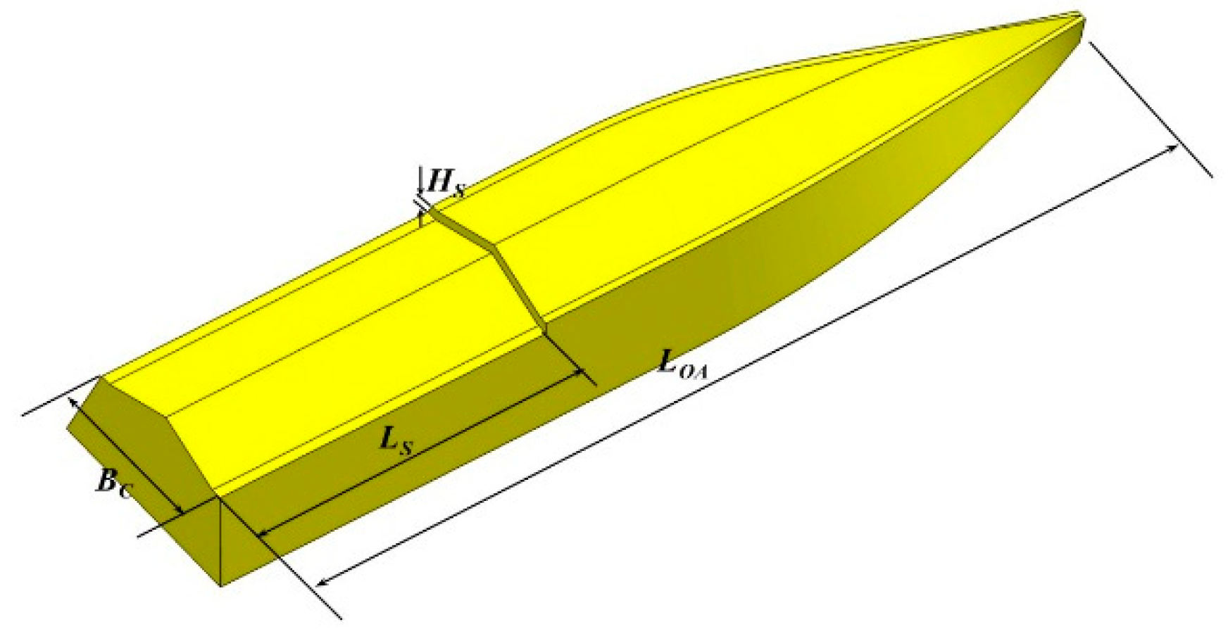
In view of the difference between the aerodynamic and hydrodynamic similarity criteria, the flow around the hull body was simulated in real scale. The monohull model was built by cutting the trimaran’s tunnel and demihulls, inheriting all the geometry features of the main hull and thus possessing a large length-to-beam ratio of 6.67. In fact, such a slender hull form is just used for the contrastive analysis here but cannot be applied in engineering due to the limited internal space.
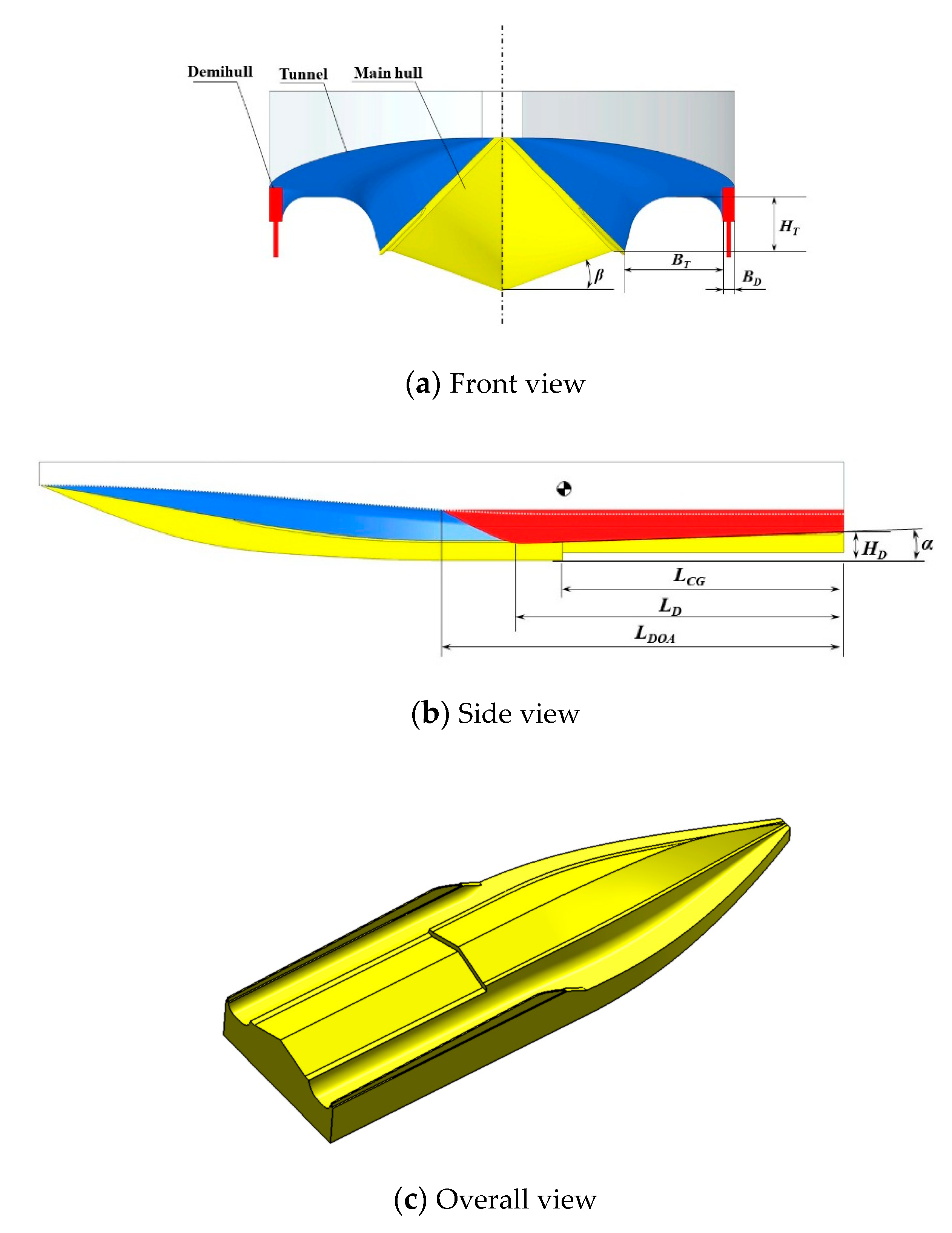
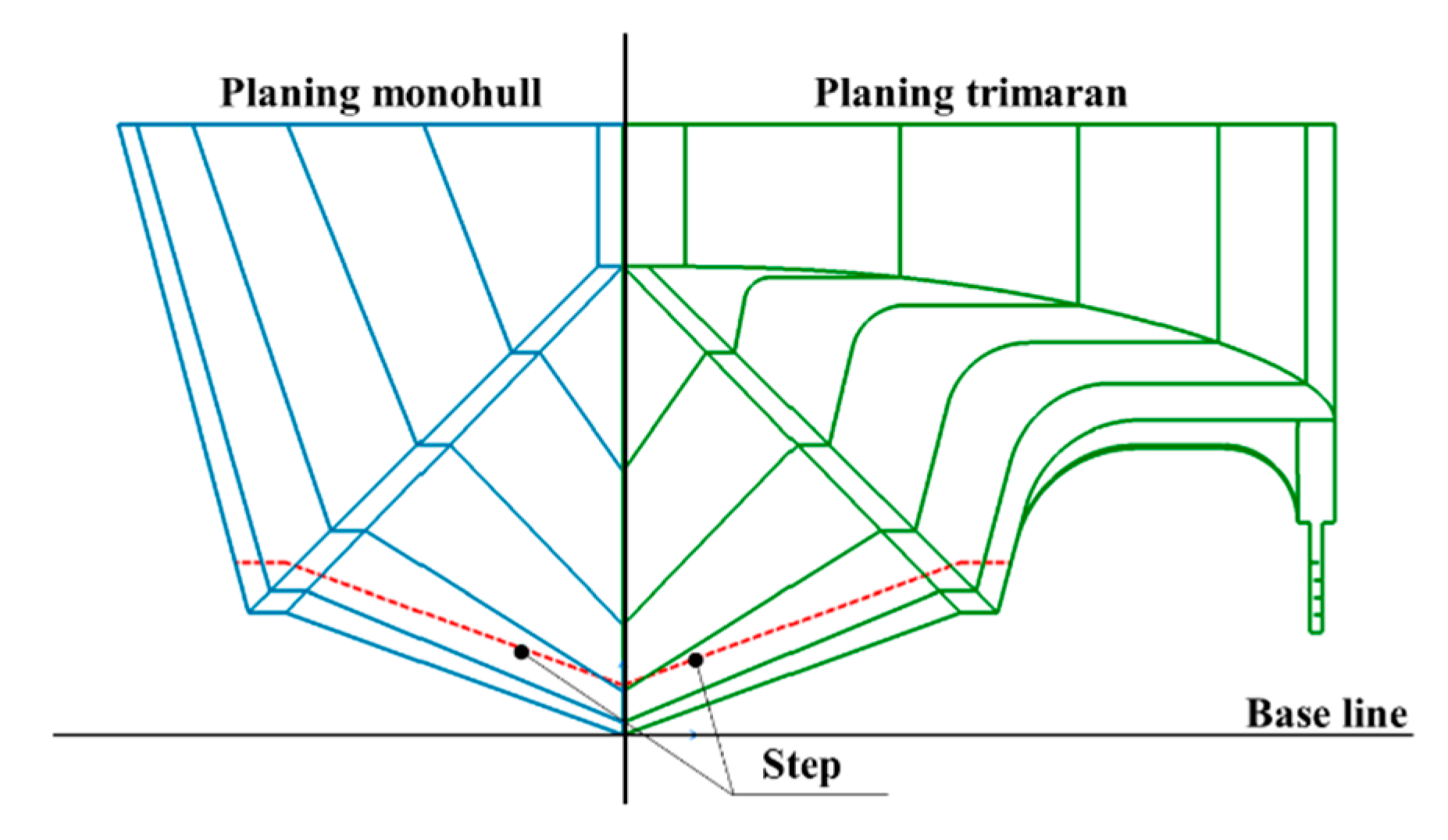
The geometry feature of the planing trimaran and slender monohull are presented in Figure 1 and Figure 2, respectively, and Figure 3 gives a comparison of body plans. The main dimensions of the ships are summarized in Table 1 and Table 2. It can be seen that the hull structure of the planing trimaran can be simplified as a main hull with two very thin demihulls, in which the tunnel roof acts as a connection bridge to joint them. The main hull is a deep-V type hull, the hull body after midship is prismatic and has a constant deadrise angle of 20°. To improve the high-speed resistance performance, a transvers step was introduced and located at the longitudinal position of 0.35 from the transom. The planing surface before and after step were parallel, and thus the aft body has a same attack angle with the fore body during forward motion. The demihull was designed to be straight along the longitudinal direction, it starts from the midship and extents to the transom; considering the bow-up motion characteristic of planing craft, the keel line of the demihull has a fore-declined angle of 2° to restrict the air flow in the tunnel region during high-speed navigation.
3. Numerical Setup
In this paper, considering the efficiency and economy, the preliminary investigations were carried out using the FVM-based commercial CFD software ANSYS CFX 13.0. As has been discussed in the related studies [14,15,16,17], this software shows good capacities in dealing with the complex problems of high-speed planing craft.
3.1. Numerical Model of Motion Solver
In the simulation of incompressible and viscous flow around the hull body, the governing equations are described by the Reynold-averaged Navier–Stokes and continuity equations. The SST (shear stress transport) turbulence model was used to close this set of governing equations since it accounts for the transport of turbulent shear stress and gives highly accurate predictions of the onset and amount of flow separation under adverse pressure gradients. The transport equation of turbulent kinetic energy, , and are defined as follows [18]:
where and represent the turbulent kinetic energies due to the average velocity gradient, , are turbulent dissipation terms, and denote the effective diffusion terms, is the orthogonal divergence term. The wave evolution and air cavity behind the step are modeled using the VOF (volume of fraction) method.
However, building the flow solver is just the first step for calculating the hydrodynamic characteristics of the high-speed planing hull, since the hull behaviors, which have significant influence on the resistance performance, change evidently as the speed is increased. Precisely estimating that this is another key problem to be solved. In this investigation, to simulate the two degree of freedom motion (pitch and heave) of the planing craft in calm water, the motion equations of force and moment equilibrium are introduced and solved as follows:
where and are the linear and angular displacement, and is the inertia mass matrix of the hull around the gravity center.
When the calculation procedure is started, governing equations are firstly solved on the initial input mesh, and the force and moment acting on the hull body are calculated by integrating pressure and shear stress around the hull surface, which are described as follows:
where , , and are the shear stress, pressure and gravity, respectively. represents the hull surfaces. and represent the displacement of mesh nodes on hull surfaces and the gravity center, respectively. Then, the linear and angular displacement can be acquired by solving Equations (3) and (4). The hull body motion is implemented using the dynamic mesh method, in CFX the grids adjacent to the hull body have little relative motion and the mesh deformation is mostly absorbed by the interior grid which is away from the domain boundary and has a larger control volume, this deformation strategy could preserve a high mesh quality during calculation. The stopping criteria of the numerical solution is satisfied when variations of force and moment are approaching to zero in a certain physical time.
3.2. Mesh Generation and Boundary Condition
Considering that the wave length is much larger than the hull length at high speed, the calculation domain is properly stretched in the longitudinal direction. Figure 4 and Figure 5 show the domain dimensions [5] and mesh-generating method. It can be seen that the calculation domain is divided into two regions, the inner region surrounding the hull body is used to capture the critical flow features, such as air cavity behind the step and wave generating in the tunnel. It is also the main target region for mesh refinement, and an unstructured mesh with tetrahedral elements was created in this region to rebuild the complex hull geometry. Since the velocity gradient in wall normal direction near the hull is large, a high resolution inflation layer mesh (about 15 layers of prism mesh) around the hull is created by extruding the surface element outwards. The outer region covering the other far field is used to simulate the wave evolution and filled with structured hexahedron element to reduce the total element number.
The boundary conditions were specified as follows. At the inlet, the velocity (both for water and air) is specified by the velocity of hull. At the outlet, hydrostatic pressure was applied. Symmetry condition was used at the central plane of the hull. The hull body was considered as a rigid body and a no-slip condition was imposed on the hull surface. Free slip condition was used for the other boundaries.
3.3. Mesh Convergence Study
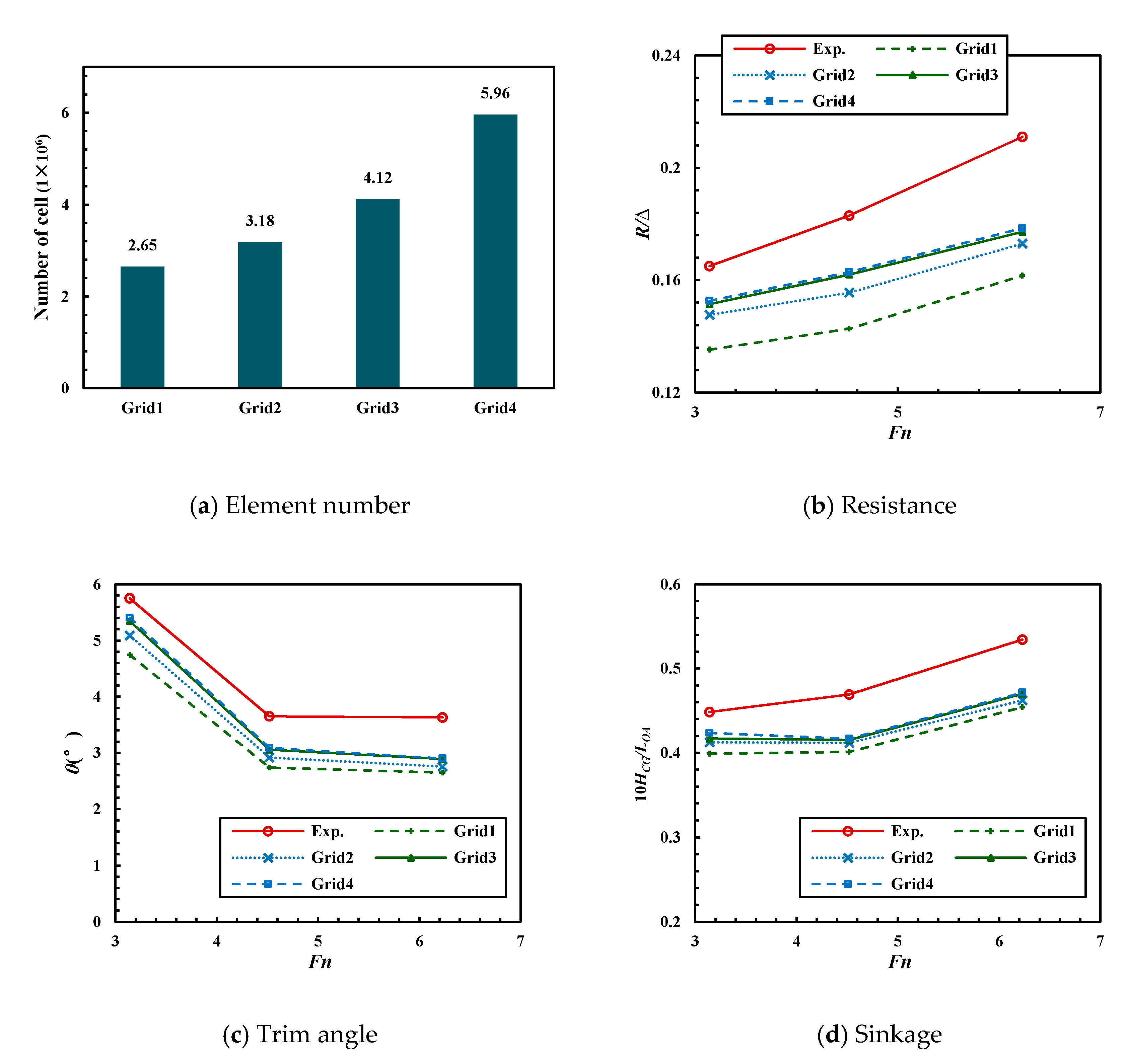
The mesh size plays an important role in the calculation procedure, as a fine mesh can always bring credible results but at the same time, increase the computational cost and time consumption due to the large element number. To determine the mesh size with an acceptable numerical accuracy and element number, mesh convergence studies are carried out based on the public experimental investigation of Jiang et al., (2016). In their investigation, a similar planing trimaran hull was tested in a towing tank, as the experimental results are in operation condition with of 130 kg, of 0.65 m and volume-based Froude number (defined by , where is the speed of hull, is the gravity acceleration, is the displacement volume) of 3.16, 4.52 and 6.23 are selected as the benchmark data in this article, respectively, to the validate numerical accuracy. Four mesh plans were generated, the basic size of surface mesh and volume mesh in the inner domain are 0.004 and 0.008 for the coarse mesh plan and gradually refined with a refinement ratio of . During the mesh refinement, the thickness of the first inflation layer was changed with a speed to keep the value on the hull bottom in the range of 100~200. The time step used in this simulation is determined by the equation below [19]:
where, is time step, is the characteristic length value.
The total element number of each plan, the calculated and experimental results of non-dimensional resistance (defined by , where is the monitored value of total resistance), trim angle and sinkage (defined by , where is the monitored value of sinkage) are summarized in Figure 6. As shown in the figure, the calculated results in most cases converged well as the mesh is refined; for instance, in the case of = 6.23, the discrepancy between Grid3 and Grid2 are 0.004°, 0.131° and 0.008° for , and , respectively, while the homogeneous discrepancy between Grid4 and Grid3 are 0.001°, 0.011° and 0.002°. It can be concluded that, when the mesh is as fine as Grid3, further refinement would lead to a large increment of the element number (about 1.84 million) and hence more computational time consumption, however, the accuracy improvement between Grid3 and Grid4 is no more significant. Therefore, Grid3 is selected as the optimum mesh plan, the mesh size of which are 0.2% on the planing surface and 0.4% in the inner domain.
In terms of the numerical accuracy, the current simulations underestimate the testing data, the discrepancy between the calculated and experimental result increases with speed. At the highest Froude number, the average error of resistance, trim angle and sinkage are 16.0, 20.5 and 12.0%, respectively. Although the relative error in trim angle seems to be larger, the value difference is only about 0.75°. Therefore, the validity of the numerical method is approved.
4. Results and Analysis
4.1. Resistance and Hull Behavior
Using the aforementioned numerical tool and mesh generation strategy, the forward motions in calm water were simulated for the monohull and trimaran at Froude numbers between 2.09 and 8.01. In Figure 7, the non-dimensional resistance, sinkage and trim angle of the monohull and planing trimaran are plotted as functions of volume-based Froude number. It can be seen from the sinkage curves that the hull body of the planing trimaran rises higher at the calculated speeds, indicating that additional lift forces, both hydrodynamic and aerodynamic, are created in the tunnel region. Influenced by these forces, the trim angle is significantly decreased, and the maximum trim angle reduction occurs at the Froude number of 3.43. As a result, the total resistance of the planing trimaran is slightly increased for Froude numbers ranging from 3.43 to 5.73, and the average increment is 4.9%.
In terms of the longitudinal motion stability, porpoising was observed for the two models at the highest speed ( = 8.01), and in Figure 8, the monitored history of resistance and pitch motion during porpoising are presented, to intuitively illustrate the real-time variation relative to the average value, for which the resistance and trim angle are represented by and , respectively, where and are the average values of resistance and trim angle in several periods, respectively. It can be seen that despite porpoising occurring at the same speed, the drag and motion oscillation amplitude of the planing trimaran is evidently weakened compared with that of monohull: the drops are 0.214 times of and 0.4°, respectively. This means that the tunnel trimming moment can suppress the hull body motion when deviating from the balance position and as a consequence, improve the longitudinal motion stability.
4.2. Flow Evolution in the Tunnel Region
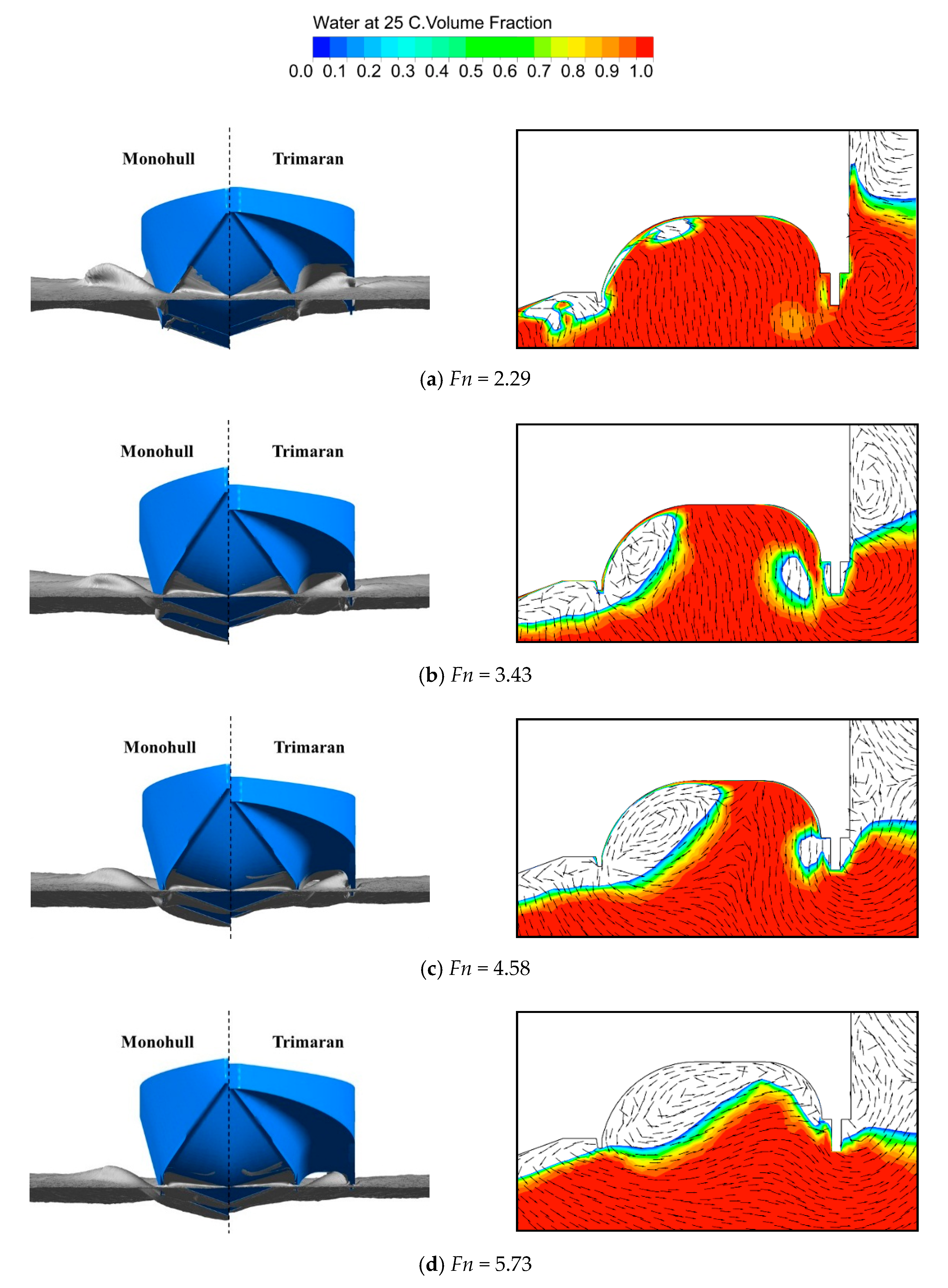
The flow in the tunnel region has a direct influence on the tunnel force and moment and will finally change the hull behavior. In Figure 9, the waves of the two models are compared in front view, and the transverse wave cut (on the cross section of = 0.1) are also performed associated with the velocity vector distribution; it should be pointed that since the hull body shakes during porpoising, steady flow information representing the hull performance is unavailable and only results of flow field at steady speeds are presented for the following analysis. According to the presented phenomenon, the flow evolution in the tunnel region could be roughly divided into three stages. In the first stage ( ≤ 3.43), a large portion of tunnel and demihull are immersed in water, the tunnel roof can be considered as a hydrodynamic planing surface which expels water outwards as the main hull does, and ventilation is not obvious and mainly occurs along the main hull chine. In the second stage (3.43 < ≤ 5.73), since the hull body is gradually lifted out of the water, more and more tunnel region is ventilated, the air enters tunnel under the downwash effect of main hull creating air whirls on the water surface; for the monohull, and the waves transmit outwards freely, whereas the waves created by the trimaran main hull are intercepted by the tunnel roof and demihull; therefore, the tunnel in this stage is actually planing on the air whirls and waves produced by the interference effects between the main hull and demihull. As the wave is further weakened, flow in the tunnel region would evolve to the final stage ( > 5.73), in which the tunnel roof could separate from the wave surface and plan on the air whirls absolutely.
Corresponding to the above three stages of flow evolution, it can be assumed that the sources of tunnel lift convert from hydrodynamic to hybrid hydrodynamic and aerodynamic and finally, to wholly aerodynamic forces. To prove this viewpoint, the tunnel is longitudinally divided into twenty sections, and the lift coefficient of each section (defined by , where is the lift force calculated by pressure integration) is plotted as a function of longitudinal location and compared with the tunnel wetted length in Figure 10. As it can be seen from the comparison of wetted length and lift distribution, the overall tendency is that the hump of the lift curve moves astern with the decreasing wetted length due the presence of hydrodynamic forces. In the first stage, the tunnel lift is mainly concentrated in the wetted region, whereas after the tunnel enters the second stage, there is a considerable portion of lift distributing beyond the wetted range, indicating that the aerodynamic forces has become significant. When the tunnel is entirely ventilated, the declined wave surface weakens the ram pressure effect of the tunnel shell on air whirls, therefore the tunnel lift in each section is evidently decreased in the final stage.
The immediate effect of flow evolution is the variation of tunnel lift and the moment which are treated as external factors of the hydrodynamic-supported main hull in James and Collu’s strategy. In Figure 11 and Figure 12, the tunnel lift coefficient, wetted area, and moment coefficient (defined by , where represents the total trimming moment of the two tunnels) as well as the longitudinal location of pressure center of the tunnel are plotted as functions of the Froude number.
It can be seen that during the ventilation process, the wetted area keeps decreasing, while the lift coefficient peaks at the Froude number of 4.58 and drops dramatically when the aerodynamic forces become dominated in the tunnel lift forces. Corresponding to the variation of tunnel wetted length, the pressure center moves astern at lower speeds since the hydrodynamic lift mainly concentrates on the rear tunnel, making the trimming moment increase; while it would return to the front in the final stage as the aerodynamic forces distribute relatively evenly in the longitudinal direction, accordingly, the tunnel trimming moment decreases sharply. Considering that the pressure center is always behind the gravity center, the tunnel trimming moment would create a bow-down effect on the hull body.
Most of the tunnel is immerged in water at lower speeds, which could create significant force, a trimming moment and additional wetted area, and because of this, the resistance of trimaran increases and the trim angle decreases evidently. On the other hand, as the tunnel ventilation becomes sufficient, the tunnel gradually separates from the water surface and its influence on the main hull is weakened, as the high-speed resistance and hull behavior of the two models tend to be close as well.
4.3. The Influence of Tunnel on the Stepped Main Hull
The bottom view of the free surface of the monohull and trimaran are compared in Figure 13, from which the main wetted region can be clearly identified. It can be seen that since the trim angle is decreased under the influence of a tunnel trimming moment, the air cavity of the main hull develops faster and thus could decrease more wetted area on the aft planing surface. However, the wetted area on the fore planing surface is enlarged, especially for Froude numbers of 3.43 and 4.58, the speeds at which the trim angle discrepancy between the two models is most obvious. Taking account of the additional wetted region of the tunnel and demihulls, the total wetted area (shown in Figure 14) of the planing trimaran increases evidently at lower speed compared with that of the monohull, but benefiting from the tunnel ventilation and additional aerodynamic lift, it would drop to the similar level with the monohull and finally exceed at the Froude number of 6.87. For this reason, the tunnel does not present a drag-reducing effect until the highest speeds before porpoising.
4.4. Incremental Research on Demihull Length
As discussed above, the tunnel lift always acts on the region shielded by demihulls, which means that the lift distribution in the tunnel may, to some degree, be determined by the longitudinal stretch of the demihull. However, the configuration design of the demihull is often easily neglected in hull form design in the public research. Therefore, in the following section, a detailed numerical investigation was performed to find the relationship between the demihull stretch and hull performance. As shown in Figure 15, four new models were built with a demihull length approximately ranging from 0.3 to 0.5 ; for the purpose of discussion, the modified models are named based on the percentage of demihull length from the length overall.
Using the same numerical setup, forward motion in calm water was simulated for these models. The calculated resistance, trim angle and sinkage of the original and modified models were summarized in Figure 16a–c, the oscillation amplitudes in the resistance and pitch motion (represented by and , the subscript max and min identify the maximum and minimum value in one period) during porpoising are performed as well. A clear dependence on the demihull length can be observed for both the resistance and hull behavior, as the demihull length increases the high-speed resistance performance ( > 4.58) is evidently improved; compared with the original model, model 50, which has the longest demihull, presents a maximum drag reduction of 8.9% at the Froude number of 6.87; while, the variation of peak resistance at lower speeds shows an opposite trend, a drag reduction of 5.5% is reported for model 30 at the Froude number of 3.43. In terms of the hull behaviors, both the trim angle and sinkage increase with the increasing demihull length, but the discrepancy of the latter is not obvious. It should be pointed that the drag-reducing effect is acquired at the expense of motion stability, in Figure 16d, the oscillation amplitude during porpoising increases as the resistance is reduced.
In Figure 17, the lift distribution in the tunnel region of different models at the steady speeds are compared. According to the wave-making characteristics in the tunnel region, at lower speeds the separation point of waves are located at the fore mainhull region, and extending the demihull could intercept more waves to provide hydrodynamic lift. Therefore, at the Froude number of 2.29 the lift hump moves forwards as the demihull length is enlarged. With the increasing speed, the wave angle decreases and most waves could be absorbed by tunnel, in such a condition that the lift hump of different models overlap in the longitudinal direction, indicating that the variation of the demihhull length has little influence on the wave form in the tunnel region.
However, the influence of demihull length on tunnel flow is mainly reflected in the final stage defined in the above analysis. At such speeds, all the lift curves seem to converge at the location of = 0.22; the aft peak value, which is strongly related with the waves in the tunnel region, drops rapidly as the increasing demihull length, indicating that the tunnel roof can separate from the wave surface earlier; while, the fore aerodynamic lift increases and its impact range extends forwards, which could make up the lift loss in the rear.
The variation of lift distribution would directly change tunnel forces and moments. In Figure 18, to clearly show the tendency along with the demihull stretch, the lift and trimming moment of the tunnel are plotted as functions of demihull length. It can be seen from the lift curves that since the model with a longer demihull possesses a larger lifting surface, the total tunnel lift could increase slowly with increasing demihull length at most speeds. However, at the Froude number of 5.73, the separation between the tunnel roof and wave surface brings forward the models with a longer demihull, as the lift is created by aerodynamic forces which are obviously smaller than that created by water; because of this, the total lift would decrease and the lift curve shows a quite different tendency.
The trimming moment decreases with the increasing demihull length in the whole speed range, and the downtrend becomes sharp at higher speeds as well because the aerodynamic forces gradually concentrated to the fore tunnel. The ability of the tunnel to suppress hull body trimming is weakened; therefore, for model 45 and model 50, the trim angle increases and the longitudinal motion stability worsen. In general, the demihull length affects the hull behavior significantly: as the demihull extends forward, tunnel lift increases but the trimming moment is weakened. Accordingly, the model with a longer demihull possesses better resistance performance, but its motion stability at high speed is getting worse.
5. Conclusions
In this study, the unique hybrid hydrodynamic and aerodynamic performance of the planing trimaran has been numerically investigated at the real scale. According to James and Collu’s strategy, a monohull model possessing the configuration of a trimaran main hull is built to make a reference for the discussion of hull behaviors under the effect of tunnel forces. Models with a different demihull length has been investigated to analyze the influence of demihull design on hull performance. Based on the presented results, the following conclusion can be drawn:
(1) The planing trimaran presents superiority in resistance when the Froude number is above 6.87, the speed at which tunnel roof separates from the waves; the created aerodynamic forces can alleviate the hull weight and decrease the total wetted area.
(2) Porpoising is observed for both the planing trimaran and monohull. The pressure center in the tunnel region is always behind the gravity center, and thus the tunnel trimming moment can suppress porpoising by weakening the oscillation amplitudes.
(3) A longitudinally stretching demihull could obviously reduce the total resistance, but the improvement of resistance performance is always accompanied by the loss of motion stability. This is principally because the aerodynamic force distributes to the fore tunnel region, decreasing the tunnel trimming moment.
(4) Considering the practicability and fuel consumption, this simple manner of modifying demihull length is still suitable for the planing trimaran designed in the Froude number range less than 6.87.
In general, the planning trimaran possesses excellent resistance performance and motion stability and can be used in the high-speed craft design. Considering the real operation condition is rough water, the sea-keeping performance of this hull form would become the further study focus.
Author Contributions
Conceptualization, H.S. and J.Z.; methodology, H.S. and J.Z.; formal analysis, Z.S.; investigation, H.S. and S.L.; validation, H.S., J.Z. and S.L.; resources, J.Z. and S.L.; data curation, H.S. and J.Z.; writing—original draft preparation, H.S., Z.S. and S.L.; writing—review and editing, H.S.; project administration, H.S. All authors have read and agreed to the published version of the manuscript.
Funding
This work is supported by the National Natural Science Foundation of China (No. 51509055, 52071100) and the Fundamental Research Funds for the Central Universities (HEUCF180101 and 3072020CF0102).
Conflicts of Interest
The authors declare no conflict of interest. The funders had no role in the design of the study; in the collection, analyses, or interpretation of data; in the writing of the manuscript, or in the decision to publish the results.
References
- James, D.; Collu, M. Aerodynamically alleviated marine vehicle (AAMV): Bridging the maritime to air domain. In Proceedings of the 13th International Conference on Fast Sea Transportation (FAST), Washington, DC, USA, 1 September 2015. [Google Scholar]
- Collu, M.; Williams, W.A.G.; Patel, M.H.; Trarieux, F. Aerodynamically alleviated marine vehicles (AAMV): Development of a mathematical framework to design high speed marine vehicle with aerodynamic surfaces. In Proceedings of the International Conference on High Performance Marine Vehicles (HPMV09), Shanghai, China, 1 April 2009. [Google Scholar]
- Shipps, P. Hybrid ram-wing planing craft-Today’s raceboats, tomorrow’s outlook. In Proceedings of the Advanced Marine Vehicles Conference, Arlington, TX, USA, 20 September 1976; pp. 607–634. [Google Scholar]
- Jiang, Y.; Sun, H.; Zou, J.; Hu, A.; Yang, J. Analysis of tunnel hydrodynamic characteristics for planing trimaran by model tests and numerical simulations. Ocean Eng. 2016, 113, 101–110. [Google Scholar] [CrossRef]
- Jiang, Y.; Sun, H.; Zou, J.; Hu, A.; Yang, J. Experimental and numerical investigations on hydrodynamic and aerodynamic characteristics of the tunnel of planing trimaran. Appl. Ocean Res. 2017, 63, 1–10. [Google Scholar] [CrossRef]
- Du, L.; Sun, H.; Jiang, Y.; Li, P. Numerical Research on the Resistance Reduction of Air Intake. Water 2019, 11, 280. [Google Scholar] [CrossRef] [Green Version]
- Yousefi, R.; Shafaghat, R.; Shakeri, M. High-speed planing hull drag reduction using tunnels. Ocean Eng. 2014, 84, 54–60. [Google Scholar] [CrossRef]
- Moghadam, H.K.; Shafaghat, R.; Yousefi, R. Numerical investigation of the tunnel aperture on drag reduction in a high-speed tunneled planing hull. J. Braz. Soc. Mech. Sci. Eng. 2015, 37, 1719–1730. [Google Scholar] [CrossRef]
- Ghassabzadeh, M.; Ghassemi, H. An innovative method for parametric design of planing tunnel vessel Hull form. Ocean Eng. 2013, 60, 14–27. [Google Scholar] [CrossRef]
- Ghassabzadeh, M.; Ghassemi, H. Determining of the hydrodynamic forces on the multi-hull tunnel vessel in steady motion. J. Braz. Soc. Mech. Sci. Eng. 2013, 36, 697–708. [Google Scholar] [CrossRef]
- Ma, W.; Sun, D.H.; Sun, D.H.; Zou, D.J.; Zhuang, J. Test studies of the resistance and sea keeping performance of trimaran planing hull. Pol. Marit. Res. 2015, 22, 22–27. [Google Scholar] [CrossRef] [Green Version]
- Ma, W.; Sun, H.; Zou, J.; Yang, H. Test research on the resistance performance of high-speed trimaran planing hull. Pol. Marit. Res. 2013, 20, 45–51. [Google Scholar] [CrossRef] [Green Version]
- Su, Y.; Wang, S.; Shen, H.-L.; Du, X. Numerical and experimental analyses of hydrodynamic performance of a channel type planing trimaran. J. Hydrodyn. 2014, 26, 549–557. [Google Scholar] [CrossRef]
- Lotfi, P.; Ashrafizaadeh, M.; Esfahan, R.K. Numerical investigation of a stepped planing hull in calm water. Ocean Eng. 2015, 94, 103–110. [Google Scholar] [CrossRef]
- Veysi, S.T.G.; Bakhtiari, M.; Ghassemi, H.; Ghiasi, M. Toward numerical modeling of the stepped and non-stepped planing hull. J. Braz. Soc. Mech. Sci. Eng. 2014, 37, 1635–1645. [Google Scholar] [CrossRef]
- De Marco, A.; Mancini, S.; Miranda, S.; Scognamiglio, R.; Vitiello, L. Experimental and numerical hydrodynamic analysis of a stepped planing hull. Appl. Ocean Res. 2017, 64, 135–154. [Google Scholar] [CrossRef]
- Dashtimanesh, A.; Esfandiari, A.; Mancini, S. Performance Prediction of Two-Stepped Planing Hulls Using Morphing Mesh Approach. J. Ship Prod. Des. 2018, 34, 236–248. [Google Scholar] [CrossRef]
- Menter, F.R.; Kuntz, M.; Langtry, R. Ten years of industrial experience with the SST turbulence model. Heat Mass Transf. 2003, 4, 625–632. [Google Scholar]
- De Luca, F.; Mancini, S.; Miranda, S.; Pensa, C. An Extended Verification and Validation Study of CFD Simulations for Planing Hulls. J. Ship Res. 2016, 60, 101–118. [Google Scholar] [CrossRef]
Figure 1.
General particulars of the planing trimaran.

Figure 2.
General particulars of the planing monohull.

Figure 3.
Body plans of the planing trimaran and monohull.

Figure 4.
Calculation domain and boundary condition.

Figure 5.
Mesh generation.

Figure 6.
Element number of different mesh plans and calculated results for the mesh convergence study.
Figure 6.
Element number of different mesh plans and calculated results for the mesh convergence study.

Figure 7.
Comparisons of the resistance, trim angle and sinkage between planing trimaran and monohull.
Figure 7.
Comparisons of the resistance, trim angle and sinkage between planing trimaran and monohull.

Figure 8.
Monitored history of resistance and trim angle during porpoising.

Figure 9.
Wave comparisons between the two models (left), and transverse wave pattern and velocity vector in the tunnel region (right).
Figure 9.
Wave comparisons between the two models (left), and transverse wave pattern and velocity vector in the tunnel region (right).


Figure 10.
Tunnel lift distribution and wetted length at different speeds.

Figure 11.
Lift coefficient and non-dimensional wetted area of tunnel.

Figure 12.
Trimming moment coefficient and longitudinal location of the pressure center of the tunnel.
Figure 12.
Trimming moment coefficient and longitudinal location of the pressure center of the tunnel.

Figure 13.
Free surface comparisons between the planing trimaran and monohull.

Figure 14.
Comparison of total wetted area between the trimaran and monohull.

Figure 15.
Demihull configuration of the original and modified models.

Figure 16.
Comparisons of resistance, trim angle, sinkage and oscillation amplitudes during porpoising between the original and modified models.
Figure 16.
Comparisons of resistance, trim angle, sinkage and oscillation amplitudes during porpoising between the original and modified models.


Figure 17.
Comparisons of the longitudinal distribution of the tunnel lift.


Figure 18.
Comparisons of the tunnel lift, trimming moment and longitudinal location of the pressure center.
Figure 18.
Comparisons of the tunnel lift, trimming moment and longitudinal location of the pressure center.


Table 1.
General particulars of the trimaran.
| Main Feature | Symbol | Value |
|---|---|---|
| Displacement (t) | 3.75 | |
| Length overall (m) | 10 | |
| Beam overall (m) | 2.85 | |
| Main hull beam (m) | 1.5 | |
| Longitudinal center of gravity (m) | 3.5 | |
| Tunnel beam (m) | 0.6 | |
| Tunnel height (m) | 0.2 | |
| Longitudinal location of step (m) | 3.5 | |
| Step height (m) | 0.1 | |
| Demihull length (m) | 4 | |
| Overall length of demihull (m) | 5 | |
| Demihull beam (m) | 0.075 | |
| Demihull height (m) | 0.345 | |
| Declination angle of demihull (°) | 2 | |
| Deadrise angle (°) | 20 | |
| Draft at transom (m) | 0.565 | |
| Hydrostatic trim angle (°) | 0.75 | |
| Static wetted area (m2) | 22.2 |
Table 2.
General particulars of the monohull.
| Main Feature | Symbol | Value |
|---|---|---|
| Displacement (t) | 3.75 | |
| Length overall (m) | 10 | |
| Beam overall (m) | 2.0 | |
| Chine beam (m) | 1.5 | |
| Longitudinal center of gravity (m) | 3.5 | |
| Longitudinal location of step (m) | 3.5 | |
| Step height (m) | 0.1 | |
| Declination angle of demihull (°) | 2 | |
| Deadrise angle (°) | 20 | |
| Draft at transom (m) | 0.595 | |
| Hydrostatic trim angle (°) | 1.05 | |
| Static wetted area (m2) | 16.4 |
Publisher’s Note: MDPI stays neutral with regard to jurisdictional claims in published maps and institutional affiliations. |
© 2020 by the authors. Licensee MDPI, Basel, Switzerland. This article is an open access article distributed under the terms and conditions of the Creative Commons Attribution (CC BY) license (http://creativecommons.org/licenses/by/4.0/).
Share and Cite
MDPI and ACS Style
Sun, H.; Zou, J.; Sun, Z.; Lu, S. Numerical Investigations on the Resistance and Longitudinal Motion Stability of a High-Speed Planing Trimaran. J. Mar. Sci. Eng. 2020, 8, 830. https://doi.org/10.3390/jmse8110830
AMA Style
Sun H, Zou J, Sun Z, Lu S. Numerical Investigations on the Resistance and Longitudinal Motion Stability of a High-Speed Planing Trimaran. Journal of Marine Science and Engineering. 2020; 8(11):830. https://doi.org/10.3390/jmse8110830
Chicago/Turabian StyleSun, Hanbing, Jin Zou, Zhiyuan Sun, and Shijie Lu. 2020. "Numerical Investigations on the Resistance and Longitudinal Motion Stability of a High-Speed Planing Trimaran" Journal of Marine Science and Engineering 8, no. 11: 830. https://doi.org/10.3390/jmse8110830
Note that from the first issue of 2016, this journal uses article numbers instead of page numbers. See further details here.