
Effects of Blade Number on the Propulsion and Vortical Structures of Pre-Swirl Stator Pump-Jet Propulsors


1
School of Marine Science and Technology, Northwestern Polytechnical University, Xi’an 710072, China
2
Key Laboratory of Unmanned Underwater Vehicle, Northwestern Polytechnical University, Xi’an 710072, China
3
Science and Technology on Water Jet Propulsion Laboratory, Marine Design and Research Institute of China, Shanghai 200011, China
*
Author to whom correspondence should be addressed.
J. Mar. Sci. Eng. 2021, 9(12), 1406; https://doi.org/10.3390/jmse9121406
Submission received: 11 November 2021
/
Revised: 4 December 2021
/
Accepted: 6 December 2021
/
Published: 9 December 2021
(This article belongs to the Special Issue Computational Fluid Mechanics)
Abstract
:Reducing the noise of the underwater propulsor is gaining more and more attention in the marine industry. The pump-jet propulsor (PJP) is an extraordinary innovation in marine propulsion applications. This paper inspects the effects of blade number on a pre-swirl stator pump-jet propulsor (PJP) quantitatively and qualitatively. The numerical calculations are conducted by IDDES and ELES, where the ELES is only adopted to capture the vortical structures after refining the mesh. The numerical results show good agreement with the experiment. Detailed discussions of the propulsion, the features of thrust fluctuation in time and frequency domains, and the flow field are involved. Based on the ELES results, the vortices in the PJP flow field and the interactions between the vortices of the stator, rotor, and duct are presented. Results suggest that, though changing the blade number under a constant solidity does not affect the propulsion, it has considerable effects on the thrust fluctuation of PJP. The wakes of the stator and rotor are also notably changed. Increasing the stator blade numbers has significantly weakened the high-intensity vortices in the stator wake and, hence, the interaction with the rotor wake vortices. The hub vortices highly depend upon the wake vortices of the rotor. The hub vortices are considerably broken by upstream wake vortices when the load per rotor blade is high. In summary, the blade number is also vital for the further PJP design, particularly when the main concerns are exciting force and noise performance.
1. Introduction
Nowadays, the pump-jet propulsor (PJP) has been widely equipped in torpedos and submarines owing to its high efficiency and outstanding noise resistance. PJP is a multi-component underwater propulsor consisting of a duct and a stator and rotor vane cascades inside the duct. The stator can be installed either upstream or downstream of the rotor, whose installed position categorizes the PJPs into two main forms: the pre-swirl stator form and the rear stator form. The PJP hydrodynamics sets the characteristic performance of the underwater vehicles, and hence the PJP is receiving increased attention.
The propulsion features and flow of PJPs have been widely studied through both numerical approaches and experiments. Suryanarayana et al. [1] evaluated the PJP performance in a wind tunnel and then Suryanarayana et al. [2] evaluated the PJP performance again in a cavitation tunnel and considered the trim angle effects. Later, Suryanarayana et al. [3] obtained the cavitation performance of a PJP. Results show that the tip clearance between the rotor blade tip and the duct is the easiest cavitation place.
Since computers have become powerful, investigating the PJP via the numerical method is the main strategy. Many aspects of the PJP investigation have been studied via computational fluid dynamics (CFD), including the performance [4,5,6,7,8,9], flow characteristics [10,11,12], cavitation [13,14], and noise [15]. Besides, the panel method based on potential flow theory is an alternative to obtain the performance [16,17], which plays an important role in quickly obtaining PJP performance and optimization. In CFD, the Reynolds-averaged Navier–Stokes (RANS) approach is preferred to obtain the PJP performance and flow [4,5,6,7,8,9,10]. However, the RANS approach is not expert in modeling the turbulence structures as the Reynolds-averaged method smoothes many details. The large eddy simulation (LES) and even the direct numerical simulation (DNS) are outstanding in modeling the complex turbulence and have been successfully applied in modeling the flow around propellers [18,19,20] and a propeller blade [21]. However, it is still a challenge when employing the LES to model the whole flow field of a complex propulsor due to the mesh requirement of LES. Up to now, the hybrid RANS/LES is a compromise to model the interesting flow region, which has been employed in underwater propulsors for performance and flow details [11,12,22]. Li et al. [11] comparatively investigated the PJP wake vortical structure with different hybrid RANS/LES approaches, which suggests that the improved delayed detached eddy simulation (IDDES) and stress-blended eddy simulation (SBES) have an outstanding ability to model the wake. Then, they revealed the underlying mechanism of the wake instability [12]. Pan et al. [14] obtained the PJP cavitation performance in the hull condition via the RANS approach with the shear stress transport (SST) turbulence model. The results illustrated that the cavitation begins at the tip clearance region. The cavitation in tip clearance leakage flow enhances the leakage flow vorticty [23] and accelerates the expansion and contraction of the tip vortex [24]. These studies further suggest that controlling the tip clearance leakage flow is important. Sun et al. [15] investigated the feasibility of using a serrated trailing edge duct in a PJP for noise reduction. Su et al. [25] concluded that the force fluctuation of the rotor dominates the vibro-acoustics response caused by PJP.
As PJP is a multi-component propulsor, most investigations on PJP performance and flow are conducted focusing on the effects of these component parameters. The rotor is the working component and there is a tip clearance between the rotor blade tip and duct. The tip clearance forms a characteristic flow in the PJP flow field and significantly affects the PJP performance [6,7,9]. Ji et al. [26] assessed the effects of thickening and raking the rotor blade tip on attenuating the tip clearance flow. Decreasing or thicking and raking tip clearance considerably weakens the intensity of the tip vortices. Yu et al. [8] investigated the effects of stator incidence angle, stator-rotor spacing, and stator chord length on PJP performance, which shows that the first two parameters considerably affect the rotor force fluctuations. Huang et al. [9] studied the effects of duct main parameters on PJP performance. The expansion ratio of the duct outlet and the incidence angle of the duct also significantly affects the tip clearance flow.
The tip clearance and duct also exist in a ducted propeller. According to the investigations on the ducted propeller, the duct existence delays the wake constraction [27] and changes the tip vortex trajectory [28]. The bio-inspired blade also weakens the effects of low pressure in tip clearance leakage flow on the blade suction side [29]. For a propeller, the tip flow characterizes its wake topology. Without holding the propeller expansion area ratio, directly changing the blade number notably changes the performance [30,31,32] while the tip vorticity is not notably changed [31] as the load on per blade is not changed. Besides, the blade trailing wakes in propeller wake are restrained by increasing the skew angle [32,33].
The stator and rotor as vane cascades in a PJP, their blade numbers characterize the wake topologies of the stator and rotor, also the tip clearance leakage flow for the rotor, hence affecting the interactions between the stator, rotor, and duct, as well as the PJP wake features. As introduced before, the effects of blade number under constant solidity on the PJP performance and flow vortical structure are not considered. So, in the present work, the effects of blade number under constant solidity are investigated. In the following content, the research models and methodology are discussed in Section 2, followed by the computational setting overview in Section 3. Finally, detailed analysis and discussion are presented in Section 4, and the conclusion in Section 5.
2. Research Object
In the present work, the considered PJP model is a pre-swirl stator form, as shown in Figure 1. The basic PJP model has an eight-bladed stator ( = 8) and a six-bladed rotor ( = 6). Figure 2 presents the sketch of the flow velocity into the stator and rotor vane cascades at radius r, where , n, and are the oncoming flow velocity of the PJP, the revolution speed of the rotor, the angle of attack of the rotor blade section, respectively. The symbol V denotes the velocity, where the subscripts ‘u’ and ‘m’ indicate the circumferential and meridional components of velocity, and the subscripts ‘1’, ‘2’, and ‘3’ indicate the axial locations. The rotor diameter () is 0.1664 m and the tip clearance between the tip and the duct inside is 0.001 m. The rotor blade is zero skew and rake. The pitch angle of the rotor blade in the radial direction is given in Table 1. The stator axial length is constant in the radial direction while the pre-swirl angle of the stator blade is variable, as presented in Table 1. The stator and rotor sections are the NACA66 and NACA16 series, respectively. The blade-to-blade distance of the stator , the blade-to-blade distance of the rotor , and the chord length of the rotor blade section are sketched in Figure 2. Particulars of the duct section are given in Table 2. Table 3 gives the blade numbers of the stator and rotor of the derived PJP models. The solidities of the stator and rotor are held constant as same as the basic PJP model (S8R6). Hence, the product of the chord length and blade numbers are held constant according to the solidity definition. The PJP is mainly working behind the submarines, and hence the rudder wakes are even number. So, the blade with an even number is not considered. The stator and rotor of the derived PJP models are shown in Figure 3.
In Figure 1, two inertial reference frames are shown: a cartesian coordinate system and a cylindrical coordinate system . The PJP advance direction is the z negative direction. The rotor rotates around the z axis, and the rotation direction is right-handed. The axis direction of the cylindrical coordinate system is oriented towards the z axis.
The following dimensionless coefficients are used to describe the PJP propulsion performance:
where J is the advance coefficient. , , and are the thrust of the rotor, stator, and duct, respectively, and their corresponding dimensionless coefficients are , , and . The total thrust coefficient of PJP is defined as . and are the torques of rotor and stator, respectively, and similarly, their corresponding dimensionless coefficients are and . Unless otherwise specified, all quantities are in dimensionless form using the rotor diameter , the velocity , and the fluid density = 998.2 kg/m as reference values. The dynamic viscosity of the fluid is = 0.001003 kg/(m·s).
3. Computational Overview
3.1. Numerical Method
As discussed in Section 1, the hybrid RANS/LES [34,35] is preferred to model the flow structures in PJP investigations. So, the IDDES [11,22,36] is employed to obtain the PJP propulsion and flow as it is a further developed formulation in the hybrid RANS/LES family. In the RANS portion, the SST [37] turbulence model is employed. Considering that in the IDDES strategy, the wall boundary regions are modeled by RANS, the transition model [38] with cross-flow effect is included in the RANS portion during the IDDES calculation. Moreover, to better capture the vortical structures and reduce the RANS portion effects, the embed LES (ELES) is adopted to model the flow structures. The ELES is also a hybrid RANS/LES form, and its main difference with IDDES is that the LES region can be manually assigned. In ELES, the Wall-Adapting Local Eddy-viscosity (WALE) [39] subgrid-scale model is employed to model the turbulence where the scale is smaller than the filtering scale. In this work, the body force and gravitational acceleration are ignored.
3.2. Mesh and Computational Setting
All meshes are hexahedral structural, the details of which are presented in Figure 4. For IDDES and ELES calculations, the y+ on the model surfaces is controlled close to 1. The computational fluid domain is shown in Figure 5. The whole computational domain is a cylinder with a diameter of 10 and a length of 30. The PJP is located at 10 downstream of the inlet. The domain was divided into four subdomains for the convenience of generating mesh and modeling the rotor revolution, including the rotor domain, stator domain, outer0 domain, and outer1 domain. These divided subdomains are connected by interior interfaces. Details of mesh count are given in Table 4. The discussion on the effects of mesh density on the prediction of PJP performance is not presented in the current investigation as the meshing strategy and mesh density are based on Refs. [9,11], where more information about the discussion on mesh density can be found. Moreover, the total mesh count is more than that in previous work [9,11]. The mesh of outer0 and outer domains are further refined for better capturing the vortices in ELES calculation, where the calculations in the rotor, stator, and outer0 domains are in LES.
Figure 5 presents the boundary conditions of calculation. The turbulence intensity and turbulent viscosity ratio of the inlet are 1% and 10%, respectively. These values are based on the experiments and a previous investigation [40]. The domain outlet is a pressure outlet where constant static pressure is placed. The lateral wall is specified as a zero shear stress wall boundary. The revolution speed of the rotor is . Then, the inlet velocity is specified according to the advance coefficient J. Six advance coefficients from 0.2 to 1.2 with a step of 0.2 are considered in all IDDES calculations, while , , and are mainly considered in the ELES calculations. According to previous investigations, the timestep is the time of the rotor rotating one degree: . For IDDES, the simulation time is eight times the period of the rotor. The discussion on the force fluctuation is based on the next ten times period calculation. The ELES simulation time is also eight times the period of the rotor, and the next five times period calculation is used to get the phase-averaged flow field. The pressure-based solver in all simulations is under the SIMPLEC algorithm. The bounded central differencing scheme and bounded second-order implicit scheme are used for the momentum and time terms, respectively.
3.3. Comparison with Experiment
The y+ distribution of PJP S8R6 at J = 1.0 condition, shown in Figure 6, suggests that the near-wall mesh satisfies the y+ requirement of IDDES and ELES. The instantaneous LES region in IDDES calculation identified by the ratio of indicates that the concerned regions are in LES resolution. In ELES calculations, the stator, rotor, and outer 0 regions are all in LES resolution as these regions are further refined and manually specified. The comparison between the IDDES and experimental results is given in Figure 7, where the numerical results are the time-averaged values of the last two-period. The deviation is mainly shown in torque coefficient and has the largest value of 6.8% at . The torque deviation is potentially caused by the insufficient prediction of the friction on rotor blades. The deviation shows a larger value owing to a larger contribution of friction to torque at a high advance coefficient. Overall, the IDDES prediction has an acceptable deviation with the experiment.
4. Results and Discussion
4.1. Propulsion
Though the main purpose of changing the blade number is to inspect the thrust fluctuation and the flow characteristics, a check on the PJP loading is also needed. The total loading change of PJP is negligible when changing the blade numbers of the stator and rotor with constant solidities. As shown in Figure 8 and Figure 9, the notable relative deviations are mainly shown in the thrust and torque of the stator. The stator loading is also not affected when only changing the rotor blade number. However, the rotor loading has a noticeable but very slight change when only changing the stator blade number. Comparatively, the relative deviation on the duct loading is very small when changing the blade numbers. According to Figure 9c, increasing the blade number of the stator or rotor, the zero torque balance point moves towards the high advance coefficient. However, this movement is almost negligible.
The rotor undergoes a non-uniform oncoming flow generated by the stator and shows noticeable fluctuations of thrust and torque, as presented in Figure 10. The stator also has an obvious torque fluctuation owing to the rotor revolution. Comparatively, the thrust fluctuation is dominated by the rotor in the axial direction, while in the side directions, it is dominated by the side forces of the duct, as depicted in Figure 11, where , , , , , and indicate the side forces in the x and y directions of the rotor, stator, and duct. The duct has almost an equivalent fluctuation level of side forces to the axial thrust fluctuation of the rotor. However, the duct side force shows slight changes in fluctuant degree between different advance coefficients. Figure 12 and Figure 13 give the RMSE (root mean squared error) values of all mentioned dimensionless coefficients of all PJP models. , , and have larger RMSE values under different blade numbers. The main difference is that the fluctuation of considerably increases when PJP works at a low advance coefficient. and also have almost equivalent RMSE values, and they notably increase at heavy loading. Nevertheless, the fluctuation of and its change tendency with the PJP loading condition is not affected when changing the blade numbers.
As shown in Figure 14, has a dominant peak at the frequency of four times BPF (blade passing frequency) in the frequency domain while does not show a noticeable peak. It should be noted that the value of BPF is different for different PJP models. Unlike the fluctuation of in the side directions, the fluctuation of notably decreases in the whole frequency band when the PJP loading decreases. The range of thrust fluctuation has a considerable increment with increasing the PJP loading when the blade numbers of the rotor and stator are close, as depicted in Figure 15, where the PJP models, S8R6, S9R7, S11R9, and S13R11 have large thrust fluctuations at the heavy loading (). It is not beneficial for the thrust fluctuation in the axial direction when the rotor blade number is close to the stator’s. In the frequency domain, as shown in Figure 16, the number of dominant peaks decrease or disappear when the blade numbers between the rotor and stator are coprime. At the light loading (), a visible high peak occurs at BPF or 2BPF when the difference in blade number between the rotor and stator is large, while at the heavy loading (), the frequency curve has more peaks when the blade numbers of the rotor and stator are close. According to Figure 17 and Figure 18, the fluctuant range of the duct side force is not affected when changing the blade number. However, unlike the original model, the fluctuation of the duct side force produces visible peaks in the frequency domain, particularly when the blade numbers between the rotor and stator have a large difference. Overall, focusing on weakening the characteristic peaks of thrust fluctuation in the frequency domain, adopting a rotor and a stator with coprime blade numbers and a large difference in blade number is better. However, this configuration will exaggerate the fluctuation of side force on the duct.
4.2. Flow Field
The pressure distribution on blades determines the rotor thrust, and its low value mainly distributes on the suction side and the region under the effects of the tip clearance leakage flow. Figure 19a shows the pressure on the suction side of the rotor blade of the original PJP model at different advance coefficients. The low-pressure area on the blade leading edge decreases as the loading decreases. At the lightest loading, the low pressure mainly exists on the inner radii part of the leading edge. The tip clearance leakage flow causes considerable low pressure on the suction side near the blade tip. This low-pressure area gradually decreases and disappears as the advance coefficient goes up. Changing the blade number under a constant solidity means the total loading on the rotor or the pre-swirl effect of the stator does not change. Hence, increasing the rotor blade numbers decreases the loading per blade. As shown in Figure 19b, the pattern of pressure distribution does not change. For the low-pressure region on the suction side caused by the tip clearance leakage flow, increasing the blade number decreases its size in the chord direction but does not change its radial size. The tip clearance leakage flow is driven by the pressure difference between the pressure side and the suction side. Consequently, its relative beginning place along the blade chord is not changed.
Figure 20 presents the iso-surface lower than −0.25. The iso-surface of the low-pressure region on the leading edge of the rotor blade decreases as the loading decreases. Though the low-pressure area caused by the tip clearance leakage flow gradually thins as the loading decreases, it maintains a long distance downstream at the high advance coefficient. Besides, low pressure also occurs on the duct leading edge due to the PJP duct undergoing a large angle of attack in the open water condition. Like the pressure distribution on the blade surface, the main difference is the change of the low-pressure region in the tip clearance leakage flow under different blade numbers. Increasing the blade number weakens the effect of low-pressure in tip clearance leakage flow on the rotor suction side and decreases this low-pressure region size. However, this low-pressure region does not shorten its evolution distance downstream.
The stator has a pre-swirl effect on the rotor oncoming flow. As shown in Figure 21, increasing the advance coefficient, the inner radii of the stator blades have a considerable circumferentially wide wake, whose radial length and circumferential width depend on the flow velocity through the stator blade cascade. Besides, at the heaviest loading (), the duct leading edge forms a flow separation on the inside, exaggerating the non-uniformity of the stator wake. This phenomenon further increases the thrust fluctuation of the rotor and causes more peaks in the frequency domain when the blade number of the rotor is close to the stator’s, as discussed in Section 4.1. At the middle () and light () loadings, the aforementioned wide wake of the stator blade mainly has a notable decrease in the circumferential direction when increasing the blade number of the stator. Moreover, the velocity gradient in this wake is also weakened.
After the duct, the PJP forms a high-velocity wake, as shown in Figure 22. In the wake inner region, there exists distinguishable wake topologies of the stator and rotor (hereafter, the two wake topologies are named stator wake and rotor wake, respectively). Different style circles are used to mark the radial areas of these distinguishable wake topologies. According to the previous investigations, the two wakes come from the trailing edge wake of the inner radii blade [11,12]. The rotor wake depends on the rotor loading, while the stator wake depends on the flow velocity through the stator. However, the two wakes are concurrently weakened as the advance coefficient increases owing to their interaction [12]. Unlike the stator wake between the stator and rotor, as shown in Figure 21, increasing the stator blade number decreases the radial size of the stator wake in the PJP wake. Increasing the rotor blade number has the same tendency, but the rotor wake’s effect on the stator wake is weakened. As shown in Figure 22b, the stator wake is more distinguishable when increasing the rotor blade number and holding the stator blade number.
4.3. Vortices
The vortices in the PJP flow field are identified by the method [41,42]. Figure 23 presents the vortical structures of the original PJP model S8R6 at loading , and the size of iso-surface shows the vortex intensity. More discussion on these vortices under the effects of the mesh and turbulence model and the evolution mechanism is documented in Refs. [11,12], respectively. Here, the interaction between the duct shedding vortex (DSV) and tip clearance leakage vortex (TCLV) near the duct outlet, the interaction between the wake vortices of the stator and rotor, and hub, are mainly discussed under the effects of blade numbers, where the rotor wake vortices represent the vortices shedding from the trailing edge of the rotor blade, particularly the ones in the inner radii. More about the discrimination of these vortices are in the investigation [12].
Increasing the rotor blade number results in a blade loading decrement. As shown in Figure 24, the TCLV intensity decreases when the rotor has more blades under the same constant. Hence, the TCLV is more unstable during the evolving downstream along the contracted duct. Near the duct shrinkage stage, TCLVs become twisted. They lost their helical topologies as their intensities are not enough to maintain their shape (as depicted in Figure 24 when the rotor blade numbers are nine and eleven). Then, they are broken into ‘’ or ‘C’ shape segments. These segment vortices twine or bridge each other. Increasing the rotor loading exaggerates this phenomenon. The DSVs bridge to these upstream segment vortices at the duct outlet and many secondary vortices occur. According to the investigation on propeller vortical structure [12,43], these secondary vortices include the ones induced by primary vortices and the ones developing from the DSVs. The primary structure of TCLV is not distinguishable after the duct outlet. When the TCLV intensity is high enough to maintain its primary vortex shape, the essential break of the primary vortex comes from the DSV interaction and the development of the secondary vortices. So, the primary structure is distinguishable in the near field after the duct outlet owing to an incomplete break from secondary vortices at this time.
The stator wake includes many wake vortices interacting with the downstream rotor, as presented in Figure 25. The stator wake vortices depend on the flow velocity through them. Every stator blade forms a high-intensity vortex evolving downstream when the stator undergoes a high-velocity flow. The flow separation occurs near the duct leading edge at the heaviest loading condition and generates many vortices. As documented in the investigation [12], the aforementioned high-intensity wake vortex of the stator blade plays the main role in interacting with the rotor blade and rotor blade wake vortices.
Figure 26 shows the wake vortices of the rotor and stator under different rotor blade numbers. The evolution of rotor blade wake vortices is considerably affected due to the decrement of the intensity of per blade wake vortex. Though the total loading on the rotor is not changed, the wake vortices quickly dissipate downstream owing to the lower intensity when increasing the rotor blade number. The downstream rotor does not show noticeable effects on the wake vortices of the stator. As shown in Figure 27, increasing the stator blade number means the wake vortices per blade are weakened. However, the stator blade also has considerable separating vortices on its suction side owing to the constant camber. Increasing the stator blade number mainly affects the high-intensity vortices in the blade trailing edge wake. As the flow velocity through the stator determines these high-intensity vortices, the rotor wake vortices show a noticeable difference caused by the stator wake vortices when the PJP is at a high advance coefficient. A high-intensity vortex occurs in the wake vortices of the stator blade at the high advance coefficient () when the blade number is less (). This high-intensity vortex has a longer evolution distance downstream and successfully interacts with the rotor blade and its wake vortices. After interacting with the rotor wake vortices, the high-intensity stator wake vortices are broken into segments but show distinguishable structures after the duct outlet.
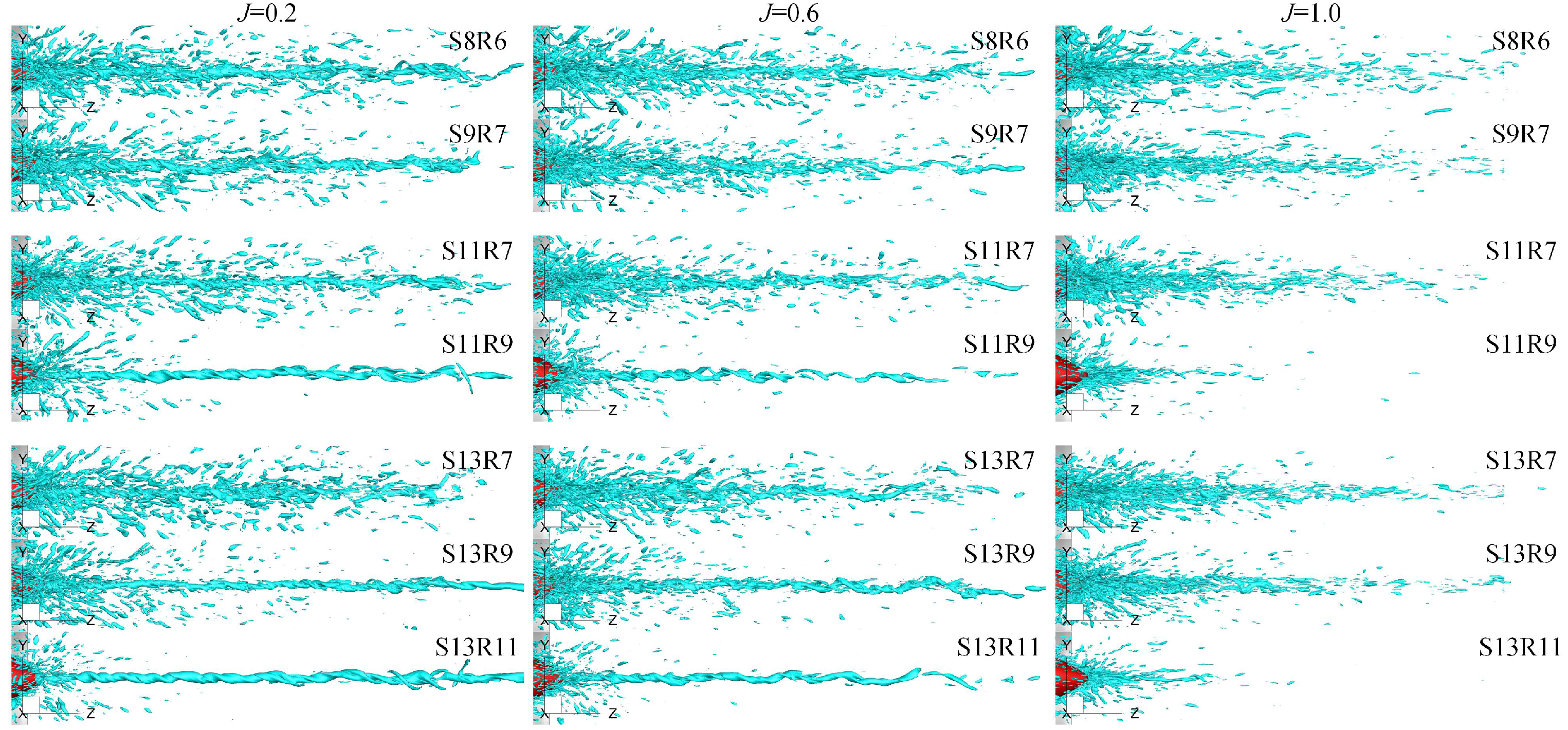
After the duct outlet, the wake vortices of the rotor and stator considerably affect the evolution of hub vortices, where the wake vortices of the rotor blade play the dominant role. The wake vortices can be weakened by increasing the blade number. Increasing the stator blade number results in a longer distance of blade wake vortices in PJP wake and a more unstable topology of hub vortices, which can be clearly evidenced from the Figure 28 where the rotor blade number is seven or nine. The effects of stator blade wake vortices on rotor wake vortices are decreased, and hence the rotor blade wake vortices can more affect the hub vortices. This phenomenon is noticeable at the low advance coefficient. However, it presents an inverse phenomenon at the high advance coefficient owing to the high-intensity vortices in the stator wake vortices when the stator blade number is less. As the rotor blade wake vortices play the main role in affecting the stability of hub vortices, increasing the rotor blade number results in fewer rotor wake vortices around the main hub vortex tube. Then, the hub vortex tube can maintain its stable primary vortex structure long distance.
5. Conclusions
In the present study, the effects of blade number on the propulsion, flow, and vortices of a pre-swirl stator pump-jet propulsor are concerned under constant solidities. The original has an eight-bladed stator and a six-bladed rotor. The stator and rotor with coprime blades numbers are derived for new PJP models. The thrust fluctuation, flow field, vortical structures of these PJP models are discussed and analyzed after discussing the derivation method of these PJP models, the numerical method, and the verification of the original PJP model. The conclusions can be drawn as follows:
- (1)
- Changing the blade number does not affect the PJP performance when the solidities of the stator and rotor are not changed;
- (2)
- Adopting coprime blade numbers of the stator and rotor decreases the peak amplitude of the rotor thrust fluctuation in the frequency domain. Nevertheless, the rotor thrust shows a large fluctuant range when the rotor blade number is close to the stators;
- (3)
- The duct side force shows a noticeable fluctuation, and a large difference in blade numbers between the stator and rotor causes high peaks in the frequency domain;
- (4)
- Increasing the rotor blade number decreases the effect range of tip clearance leakage flow on the suction side in the chord direction, while the effect range does not change in the radial direction. A rotor with more blades also results in a radially narrow core region in its wake. The intensity of the tip clearance leakage vortex is also decreased, and hence this vortex prematurely becomes more unstable before it is out of the duct. However, the total break of this vortex is completed after the interaction with the duct shedding vortex. The rotor wake vortices are notably weakened, and hence their effects on the stability of hub vortices decrease. Compared with the effects of stator wake vortices, the rotor wake vortices dominate the effects on the instability of hub vortices. Consequently, the hub vortices maintain a stable primary vortical structure with a long distance when increasing the rotor blade;
- (5)
- Increasing the stator blade number decreases the velocity gradient in the inner radii of the stator wake and results in a radial narrow stator wake in the rotor downstream. The decreased loading per stator blade weakens the high-intensity vortex in the stator wake vortices. Hence, the effects of this high-intensity vortex on the rotor wake vortices decrease.
Author Contributions
This study is the result of collaborative teamwork. Conceptualization, methodology, investigation, writing—original draft, H.L.; project administration, writing—review and editing, Q.H.; supervision, G.P.; visualization, X.D.; Software, F.L. All authors have read and agreed to the published version of the manuscript.
Funding
This research was funded by the National Natural Science Foundation of China under Grant No. 51979226, and the Fundamental Research Funds for the Central Universities under [Grant No. 3102019HHZY030019 and 3102020HHZY030018]. The APC was funded by the National Natural Science Foundation of China under Grant No. 51979226.
Institutional Review Board Statement
Not applicable.
Informed Consent Statement
Not applicable.
Data Availability Statement
The data presented in this study are available on request from the corresponding author upon reasonable request.
Conflicts of Interest
The authors declare no conflict of interest.
References
- Suryanarayana, C.; Satyanarayana, B.; Ramji, K.; Saiju, A. Experimental evaluation of pumpjet propulsor for an axi-symmetric body in wind tunnel. Int. J. Nav. Archit. Ocean Eng. 2010, 2, 24–33. [Google Scholar] [CrossRef] [Green Version]
- Suryanarayana, C.; Satyanarayana, B.; Ramji, K. Performance evaluation of an underwater body and pumpjet by model testing in cavitation tunnel. Int. J. Nav. Archit. Ocean Eng. 2010, 2, 57–67. [Google Scholar] [CrossRef] [Green Version]
- Suryanarayana, C.; Satyanarayana, B.; Ramji, K.; Rao, M.N. Cavitation studies on axi-symmetric underwater body with pumpjet propulsor in cavitation tunnel. Int. J. Nav. Archit. Ocean Eng. 2010, 2, 185–194. [Google Scholar] [CrossRef] [Green Version]
- Ivanell, S. Hydrodynamic Simulation of a Torpedo with Pumpjet Propulsion System; Royal Institute of Technology: Stockholm, Sweden, 2001. [Google Scholar]
- Shirazi, A.T.; Nazari, M.R.; Manshadi, M.D. Numerical and experimental investigation of the fluid flow on a full-scale pump jet thruster. Ocean Eng. 2019, 182, 527–539. [Google Scholar] [CrossRef]
- Li, H.; Pan, G.; Huang, Q. Transient analysis of the fluid flow on a pumpjet propulsor. Ocean Eng. 2019, 191, 106520. [Google Scholar] [CrossRef]
- Yu, H.; Zhang, Z.; Hua, H. Numerical investigation of tip clearance effects on propulsion performance and pressure fluctuation of a pump-jet propulsor. Ocean Eng. 2019, 192, 106500. [Google Scholar] [CrossRef]
- Yu, H.; Duan, N.; Hua, H.; Zhang, Z. Propulsion performance and unsteady forces of a pump-jet propulsor with different pre-swirl stator parameters. Appl. Ocean Res. 2020, 100, 102184. [Google Scholar] [CrossRef]
- Huang, Q.; Li, H.; Pan, G.; Dong, X. Effects of duct parameter on pump-jet propulsor unsteady hydrodynamic performance. Ocean Eng. 2021, 221, 108509. [Google Scholar] [CrossRef]
- Qiu, C.; Pan, G.; Huang, Q.; Shi, Y. Numerical analysis of unsteady hydrodynamic performance of pump-jet propulsor in oblique flow. Int. J. Nav. Archit. Ocean Eng. 2020, 12, 102–115. [Google Scholar] [CrossRef]
- Li, H.; Huang, Q.; Pan, G.; Dong, X. The transient prediction of a pre-swirl stator pump-jet propulsor and a comparative study of hybrid RANS/LES simulations on the wake vortices. Ocean Eng. 2020, 203, 107224. [Google Scholar] [CrossRef]
- Li, H.; Huang, Q.; Pan, G.; Dong, X. Wake instabilities of a pre-swirl stator pump-jet propulsor. Phys. Fluids 2021, 33, 085119. [Google Scholar]
- Shi, Y.; Pan, G.; Huang, Q.; Du, X. Numerical Simulation of Cavitation Characteristics for Pump-jet Propeller. J. Phys. 2015, 640, 012035. [Google Scholar] [CrossRef]
- Pan, G.; Lu, L.; Sahoo, P.K. Numerical simulation of unsteady cavitating flows of pumpjet propulsor. Ships Offshore Struct. 2016, 11, 64–74. [Google Scholar] [CrossRef]
- Sun, Y.; Liu, W.; Li, T.Y. Numerical investigation on noise reduction mechanism of serrated trailing edge installed on a pump-jet duct. Ocean Eng. 2019, 191, 106489. [Google Scholar] [CrossRef]
- Wang, C.; Weng, K.; Guo, C.; Gu, L. Prediction of hydrodynamic performance of pump propeller considering the effect of tip vortex. Ocean Eng. 2019, 171, 259–272. [Google Scholar] [CrossRef]
- Wang, C.; Weng, K.; Guo, C.; Chang, X.; Gu, L. Analysis of influence of duct geometrical parameters on pump jet propulsor hydrodynamic performance. J. Mar. Sci. Technol. 2020, 25, 640–657. [Google Scholar] [CrossRef]
- Kumar, P.; Mahesh, K. Large eddy simulation of propeller wake instabilities. J. Fluid Mech. 2017, 814, 361–396. [Google Scholar] [CrossRef]
- Ahmed, S.; Croaker, P.; Doolan, C.J. On the instability mechanisms of ship propeller wakes. Ocean Eng. 2020, 213, 107609. [Google Scholar] [CrossRef]
- Posa, A.; Broglia, R.; Balaras, E. The wake structure of a propeller operating upstream of a hydrofoil. J. Fluid Mech. 2020, 904. [Google Scholar] [CrossRef]
- Jing, Z.; Ducoin, A. Direct numerical simulation and stability analysis of the transitional boundary layer on a marine propeller blade. Phys. Fluids 2020, 32, 124102. [Google Scholar] [CrossRef]
- Long, Y.; Han, C.; Long, X.; Ji, B.; Huang, H. Verification and validation of Delayed Detached Eddy Simulation for cavitating turbulent flow around a hydrofoil and a marine propeller behind the hull. Appl. Math. Model. 2021, 96, 382–401. [Google Scholar] [CrossRef]
- Li, H.; Pan, G.; Huang, Q.; Shi, Y. Numerical Prediction of the Pumpjet Propulsor Tip Clearance Vortex Cavitation in Uniform Flow. J. Shanghai Jiaotong Univ. 2020, 25, 352–364. [Google Scholar] [CrossRef]
- Yuan, J.; Chen, Y.; Wang, L.; Fu, Y.; Zhou, Y.; Xu, J.; Lu, R. Dynamic analysis of cavitation tip vortex of pump-jet propeller based on DES. Appl. Sci. 2020, 10, 5998. [Google Scholar] [CrossRef]
- Su, Z.; Shi, S.; Huang, X.; Rao, Z.; Hua, H. Vibro-acoustic characteristics of a coupled pump-jet–Shafting system–SUBOFF model under distributed unsteady hydrodynamics by a pump-jet. Ocean Eng. 2021, 235, 109429. [Google Scholar] [CrossRef]
- Ji, X.Q.; Dong, X.Q.; Yang, C.J. Attenuation of the Tip-Clearance Flow in a Pump-Jet Propulsor by Thickening and Raking the Tips of Rotor Blades: A Numerical Study. Appl. Ocean Res. 2021, 113, 102723. [Google Scholar] [CrossRef]
- Gong, J.; Guo, C.Y.; Zhao, D.G.; Wu, T.C.; Song, K.W. A comparative DES study of wake vortex evolution for ducted and non-ducted propellers. Ocean Eng. 2018, 160, 78–93. [Google Scholar] [CrossRef]
- Villa, D.; Gaggero, S.; Tani, G.; Viviani, M. Numerical and experimental comparison of ducted and non-ducted propellers. J. Mar. Sci. Eng. 2020, 8, 257. [Google Scholar] [CrossRef] [Green Version]
- Stark, C.; Shi, W.; Troll, M. Cavitation funnel effect: Bio-inspired leading-edge tubercle application on ducted marine propeller blades. Appl. Ocean Res. 2021, 116, 102864. [Google Scholar] [CrossRef]
- Felli, M.; Guj, G.; Camussi, R. Effect of the number of blades on propeller wake evolution. Exp. Fluids 2008, 44, 409–418. [Google Scholar] [CrossRef]
- Felli, M.; Camussi, R.; Di Felice, F. Mechanisms of evolution of the propeller wake in the transition and far fields. J. Fluid Mech. 2011, 682, 5–53. [Google Scholar] [CrossRef] [Green Version]
- Malmir, R. A CFD study on the correlation between the skew angle and blade number of hydrodynamic performance of a submarine propeller. J. Braz. Soc. Mech. Sci. Eng. 2019, 41, 1–14. [Google Scholar] [CrossRef]
- Wang, L.Z.; Guo, C.Y.; Su, Y.M.; Wu, T.C. A numerical study on the correlation between the evolution of propeller trailing vortex wake and skew of propellers. Int. J. Nav. Archit. Ocean Eng. 2018, 10, 212–224. [Google Scholar] [CrossRef]
- Spalart, P.R. Comments on the feasibility of LES for wings, and on a hybrid RANS/LES approach. In Proceedings of the First AFOSR International Conference on DNS/LES, Ruston, LA, USA, 4–8 August 1997; p. 1. [Google Scholar]
- Strelets, M. Detached eddy simulation of massively separated flows. In Proceedings of the 39th Aerospace Sciences Meeting and Exhibit, Reno, NV, USA, 8–11 January 2001; p. 879. [Google Scholar]
- Gritskevich, M.S.; Garbaruk, A.V.; Schütze, J.; Menter, F.R. Development of DDES and IDDES formulations for the k-ω shear stress transport model. Flow Turbul. Combust. 2012, 88, 431–449. [Google Scholar] [CrossRef]
- Menter, F.R. Two-equation eddy-viscosity turbulence models for engineering applications. AIAA J. 1994, 32, 1598–1605. [Google Scholar] [CrossRef] [Green Version]
- Menter, F.R.; Smirnov, P.E.; Liu, T.; Avancha, R. A one-equation local correlation-based transition model. Flow Turbul. Combust. 2015, 95, 583–619. [Google Scholar] [CrossRef]
- Nicoud, F.; Ducros, F. Subgrid-scale stress modelling based on the square of the velocity gradient tensor. Flow Turbul. Combust. 1999, 62, 183–200. [Google Scholar] [CrossRef]
- Li, H.; Huang, Q.; Pan, G.; Dong, X. Assessment of transition modeling for the unsteady performance of a pump-jet propulsor in model scale. Appl. Ocean Res. 2021, 108, 102537. [Google Scholar] [CrossRef]
- Liu, C.; Wang, Y.; Yang, Y.; Duan, Z. New omega vortex identification method. Sci. China Phys. Mech. Astron. 2016, 59, 1–9. [Google Scholar] [CrossRef]
- Liu, J.m.; Wang, Y.Q.; Gao, Y.S.; Liu, C. Galilean invariance of Omega vortex identification method. J. Hydrodyn. 2019, 31, 249–255. [Google Scholar] [CrossRef]
- Di Mascio, A.; Muscari, R.; Dubbioso, G. On the wake dynamics of a propeller operating in drift. J. Fluid Mech. 2014, 754, 263–307. [Google Scholar] [CrossRef]
Figure 1.
The PJP model in experimental configuration (a) and numerical configurations (b,c).
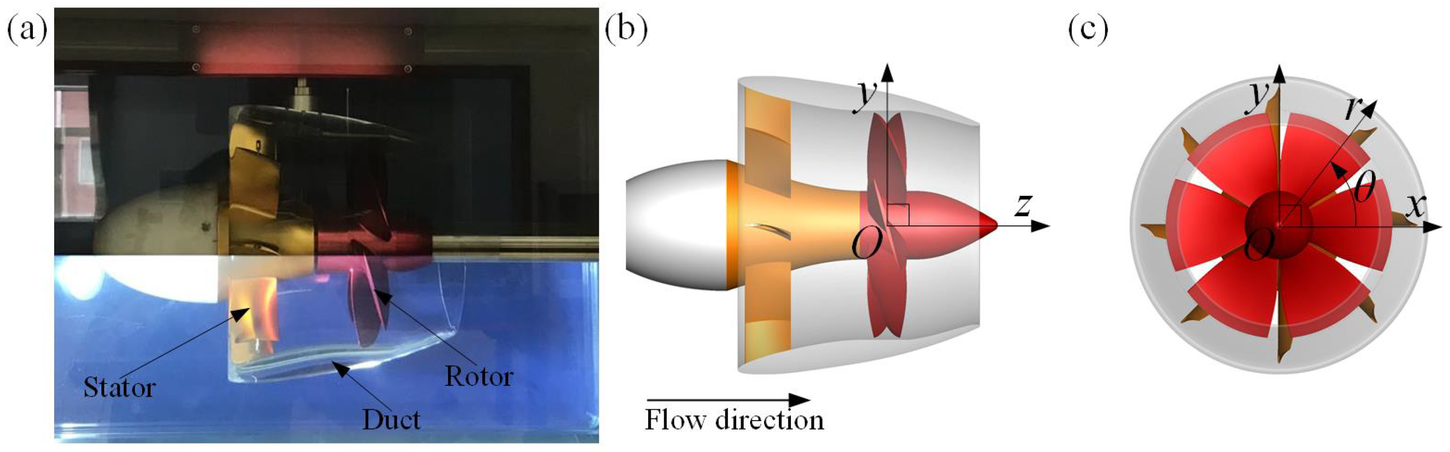
Figure 2.
The sketch of the velocity across the blades: (a) stator blades; (b) rotor blades.
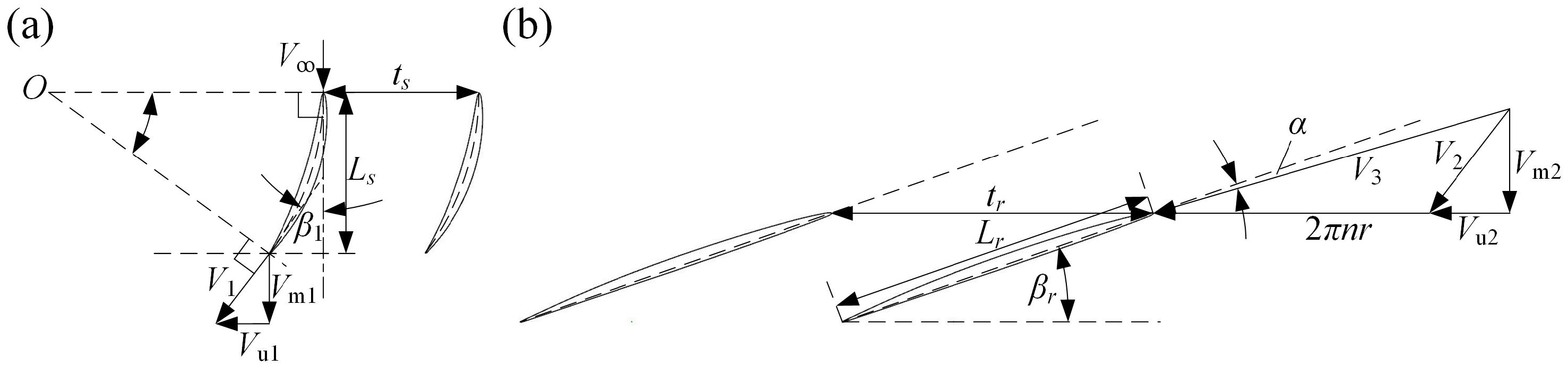
Figure 3.
The rotor and stator under different blade numbers.

Figure 4.
The PJP mesh (a–c), and the further refined mesh (d).
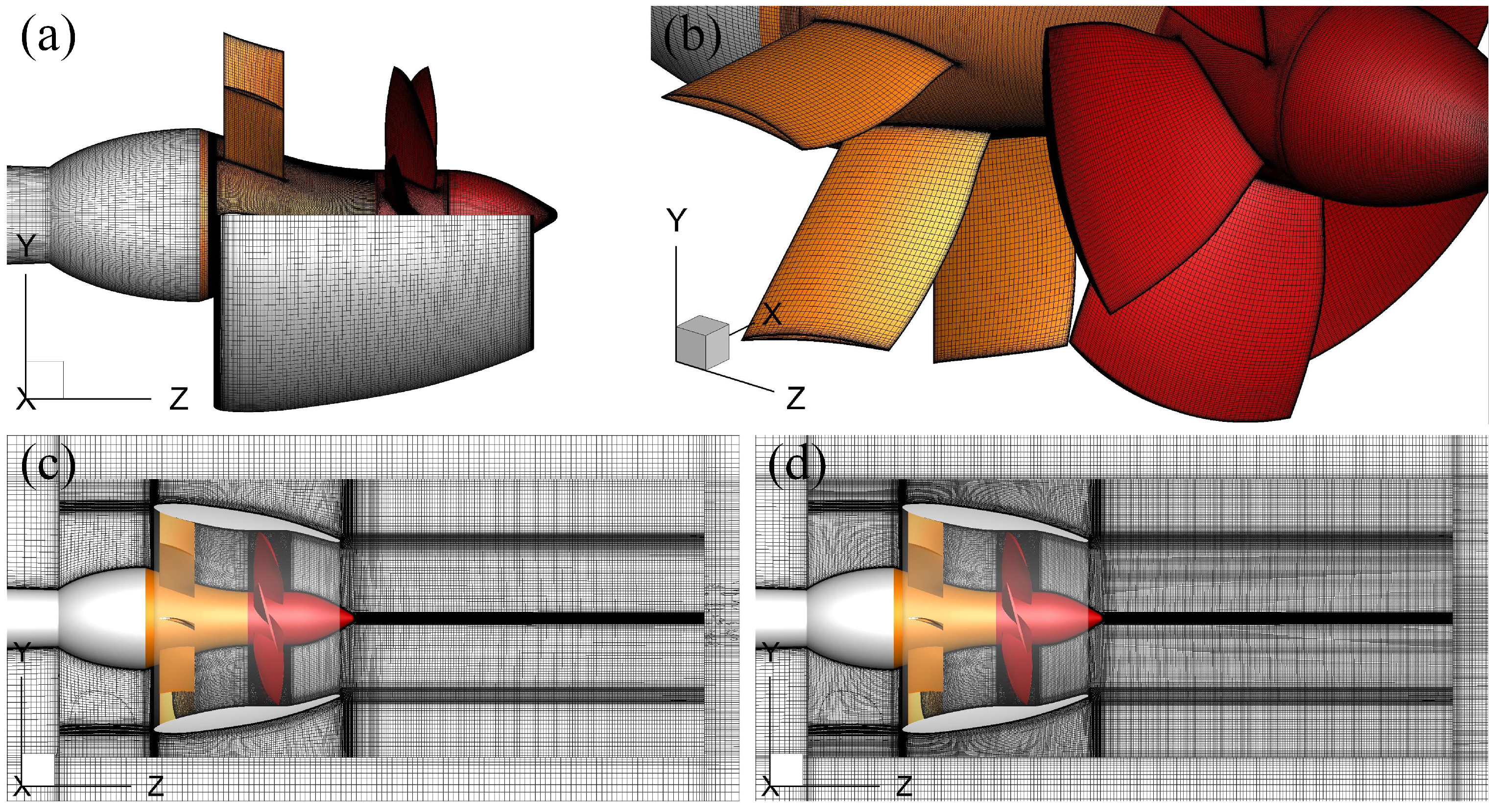
Figure 5.
The computational domain and boundary conditions.
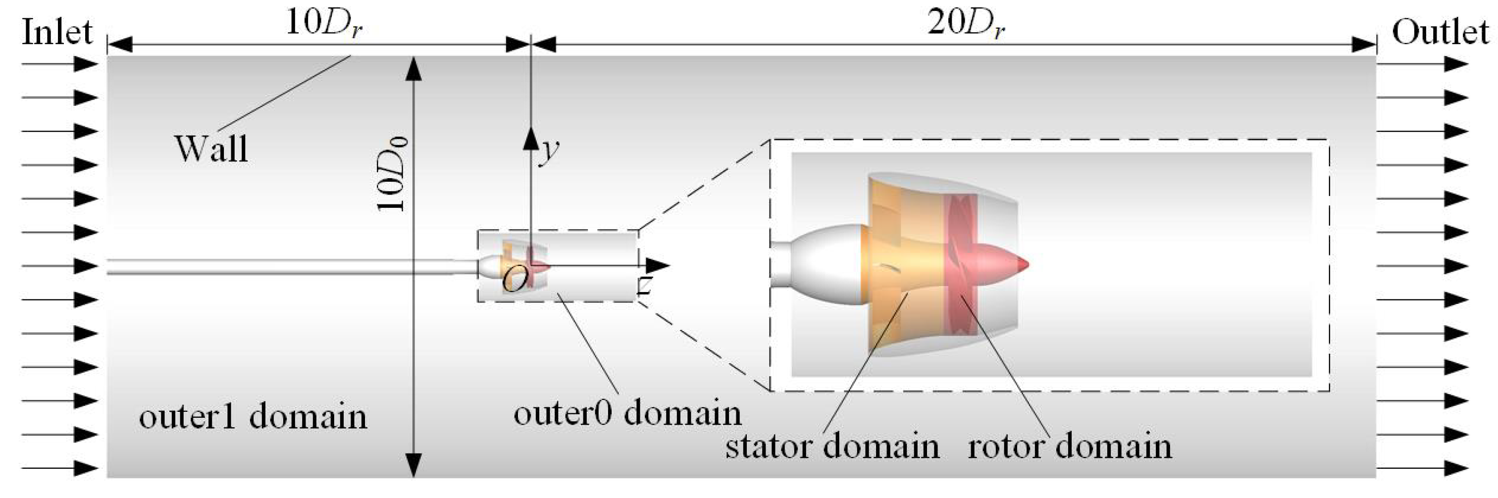
Figure 6.
(a) the y+ distribution at , and (b) the LES region in corresponding IDDES calculation, identified by the ratio .
Figure 6.
(a) the y+ distribution at , and (b) the LES region in corresponding IDDES calculation, identified by the ratio .

Figure 7.
The comparison between the numerical results and the experiment: (a) hydrodynamic curves, (b) deviation.
Figure 7.
The comparison between the numerical results and the experiment: (a) hydrodynamic curves, (b) deviation.
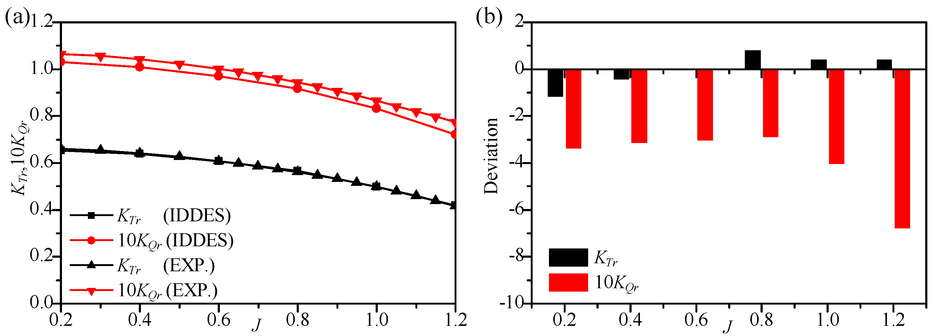
Figure 8.
Thrust coefficients of the rotor, stator, duct, and the total thrust coefficient: (a) , (b) , (c) , (d) , where , , and are normalized by the corresponding ones of PJP S8R6 at while is normalized by the corresponding one of PJP S8R6 at .
Figure 8.
Thrust coefficients of the rotor, stator, duct, and the total thrust coefficient: (a) , (b) , (c) , (d) , where , , and are normalized by the corresponding ones of PJP S8R6 at while is normalized by the corresponding one of PJP S8R6 at .
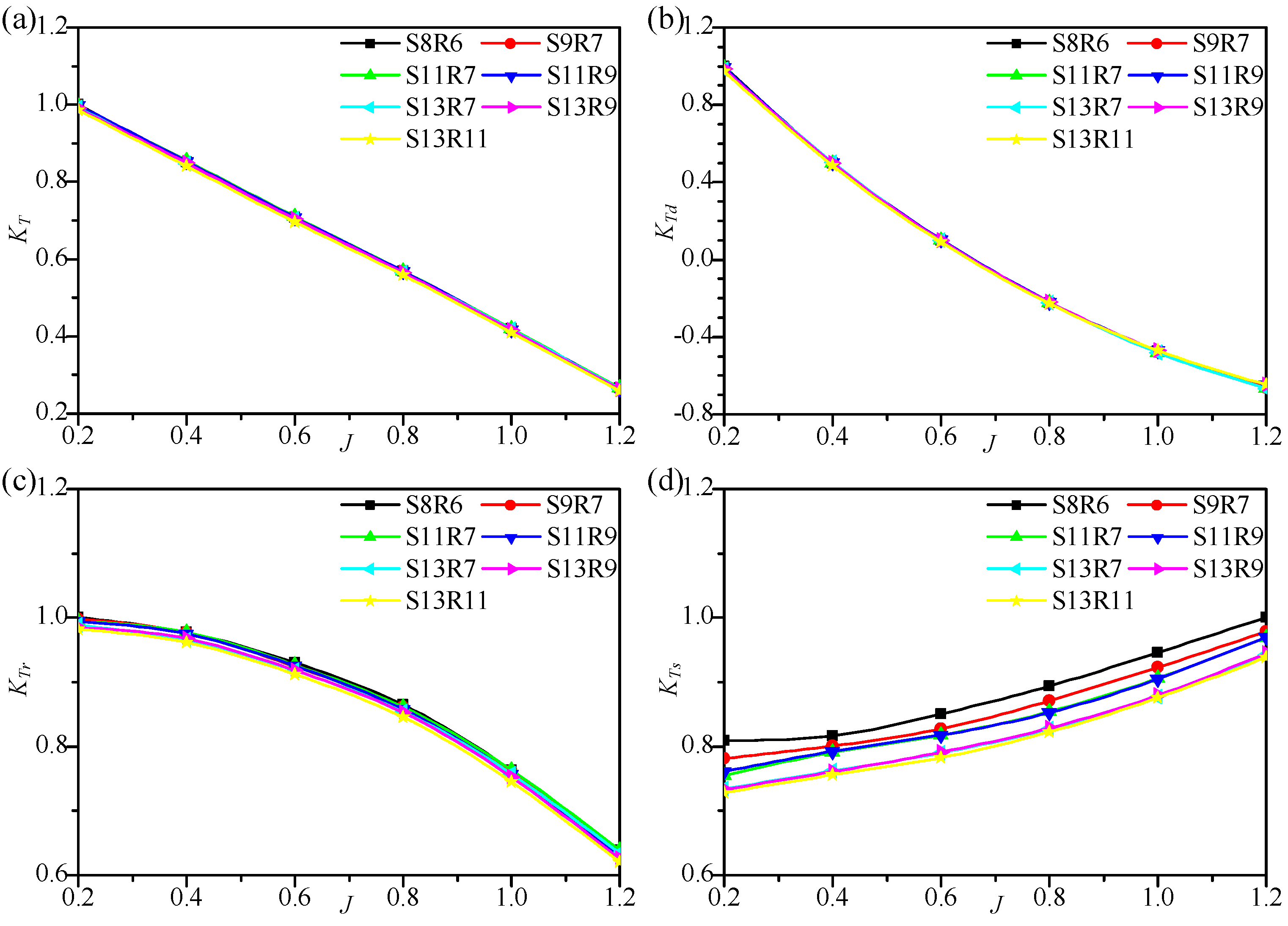
Figure 9.
Torque coefficients of the rotor and stator, and the torque coefficient difference between the rotor and stator: (a) 10, (b) 10, (c) 100, where is normalized by the corresponding one of PJP S8R6 at while is normalized by the corresponding one of PJP S8R6 at .
Figure 9.
Torque coefficients of the rotor and stator, and the torque coefficient difference between the rotor and stator: (a) 10, (b) 10, (c) 100, where is normalized by the corresponding one of PJP S8R6 at while is normalized by the corresponding one of PJP S8R6 at .
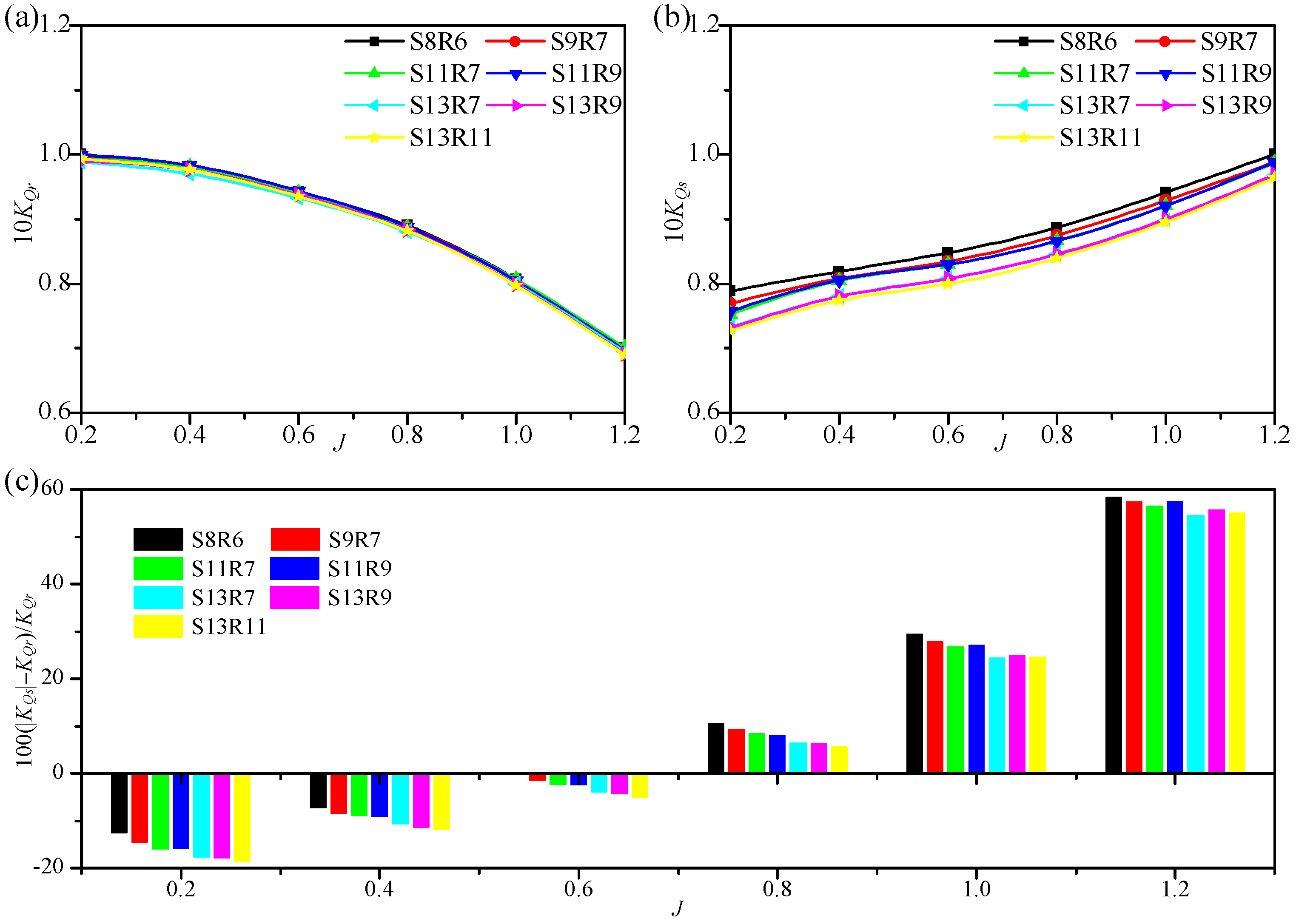
Figure 10.
Thrust and torque fluctuations of the rotor, stator, and duct of the PJP model S8R6: (a) , (b) , (c) , (d) , (e) 10.
Figure 10.
Thrust and torque fluctuations of the rotor, stator, and duct of the PJP model S8R6: (a) , (b) , (c) , (d) , (e) 10.
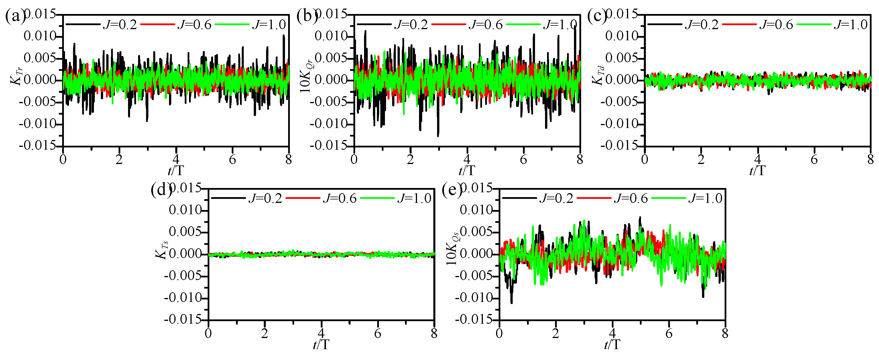
Figure 11.
Side force fluctuations of the rotor, stator, and duct of the PJP model S8R6: (a) , (b) , (c) , (d) , (e) , (f) .
Figure 11.
Side force fluctuations of the rotor, stator, and duct of the PJP model S8R6: (a) , (b) , (c) , (d) , (e) , (f) .
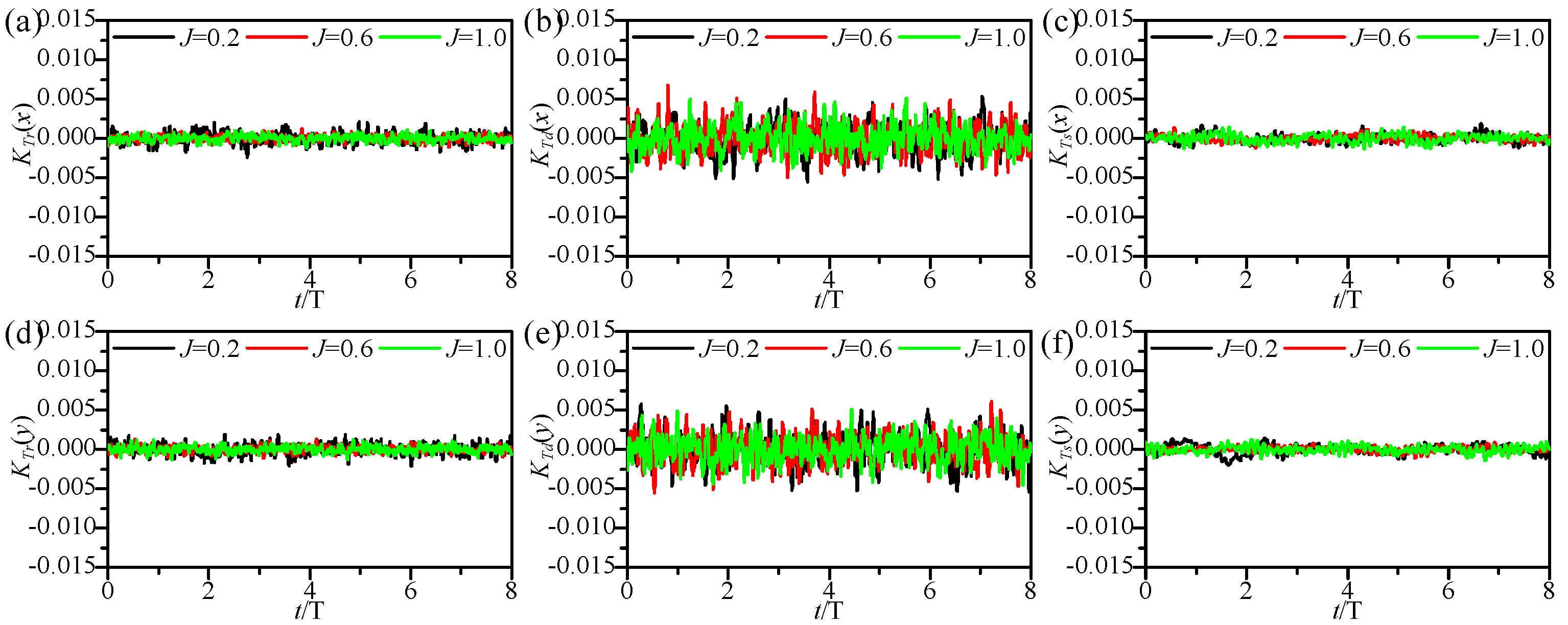
Figure 12.
RMSE values of the fluctuation component of thrust and side forces: (a) , (b) , (c) , (d) , (e) , (f) , (g) , (h) , (i) .
Figure 12.
RMSE values of the fluctuation component of thrust and side forces: (a) , (b) , (c) , (d) , (e) , (f) , (g) , (h) , (i) .
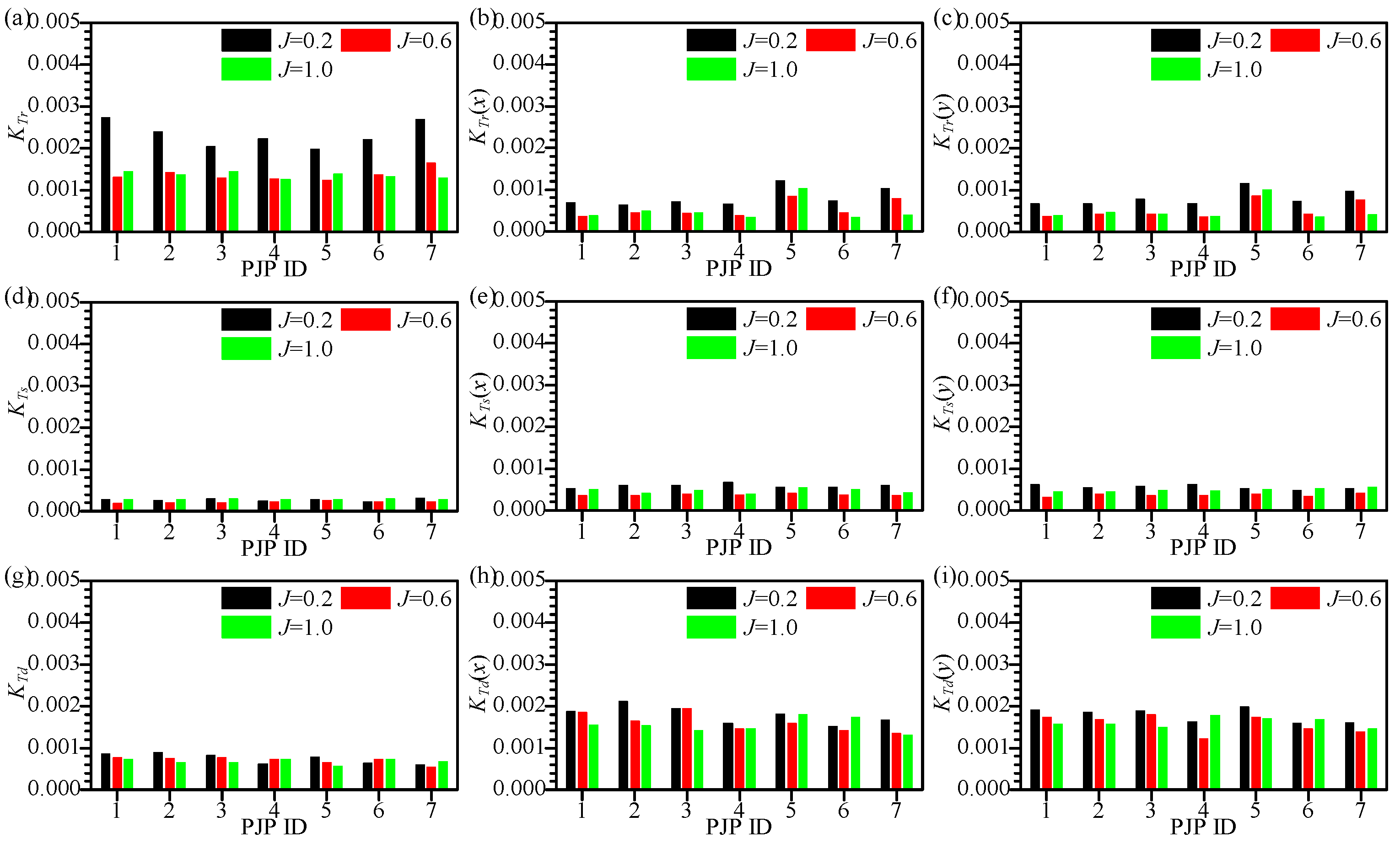
Figure 13.
RMSE values of the fluctuation component of torque: (a) 10, (b) 10.

Figure 14.
Frequency domain curves of , and of the PJP model S8R6: (a) , (b) , (c) .
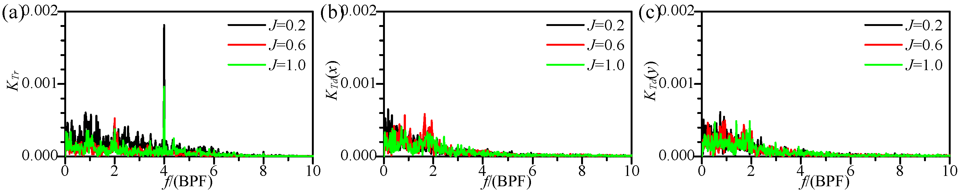
Figure 15.
Time domain curves of fluctuation component of . (from (a–f) corresponding to PJP model ID 2 to 7).
Figure 15.
Time domain curves of fluctuation component of . (from (a–f) corresponding to PJP model ID 2 to 7).
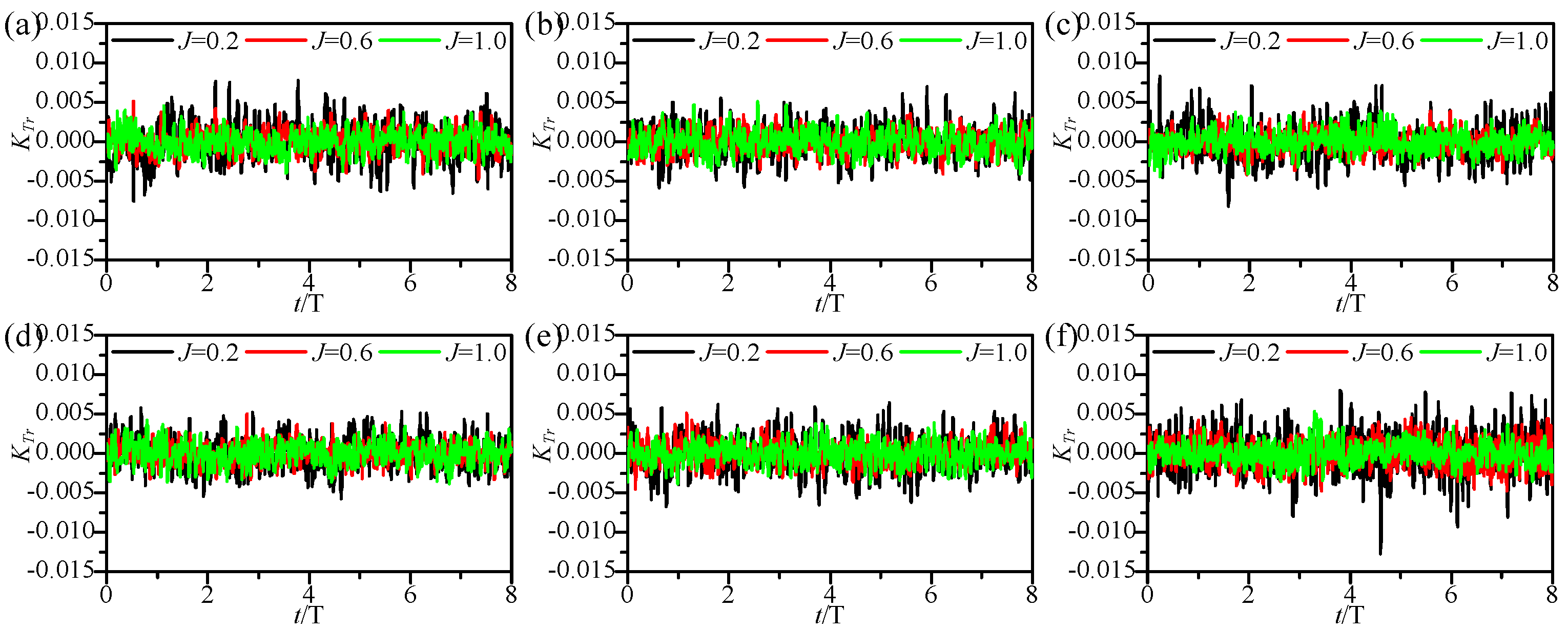
Figure 16.
Frequency domain curves of fluctuation component of . (from (a–f) corresponding to PJP model ID 2 to 7).
Figure 16.
Frequency domain curves of fluctuation component of . (from (a–f) corresponding to PJP model ID 2 to 7).
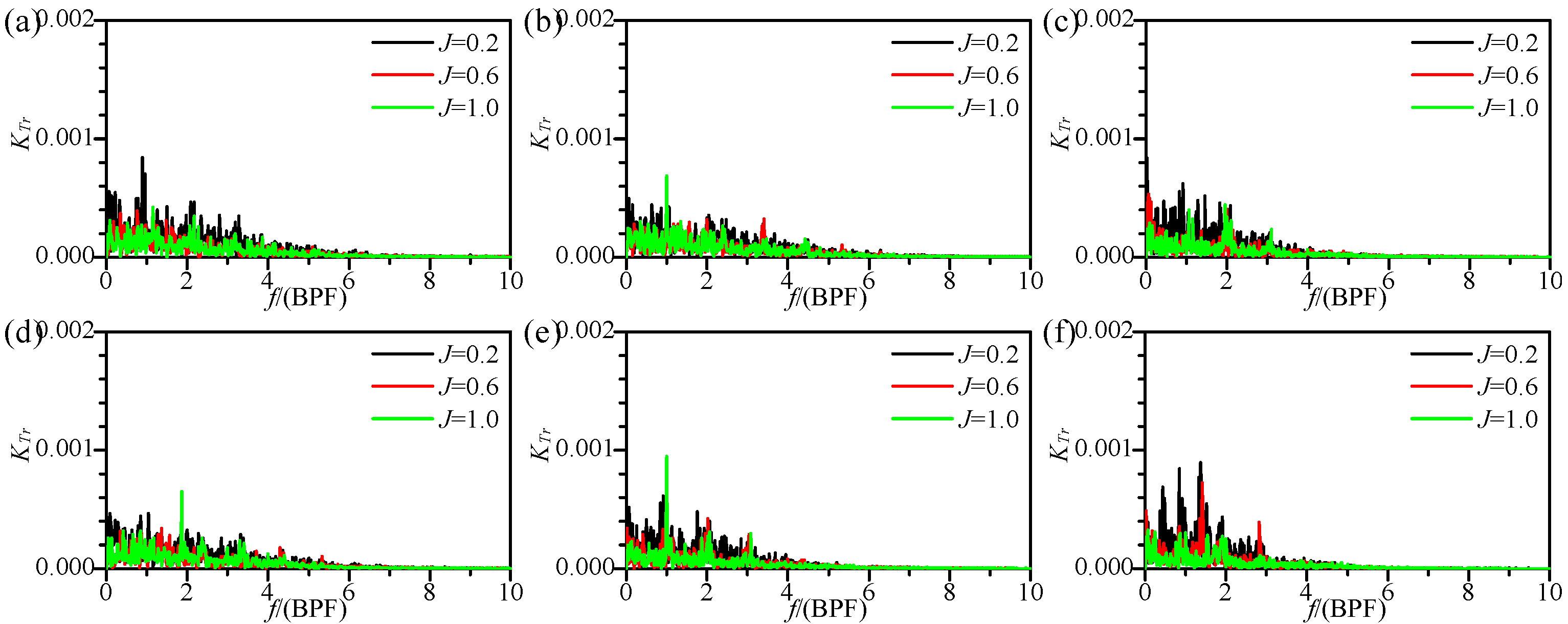
Figure 17.
Time domain curves of fluctuation component of . (from (a–f) corresponding to PJP model ID 2 to 7).
Figure 17.
Time domain curves of fluctuation component of . (from (a–f) corresponding to PJP model ID 2 to 7).
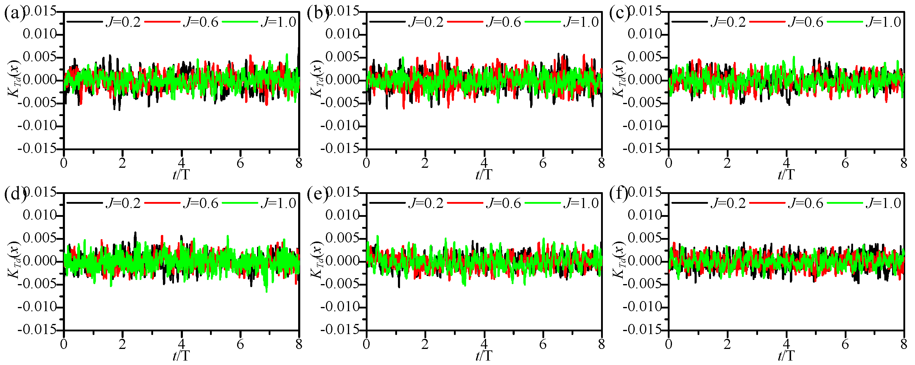
Figure 18.
Frequency domain curves of fluctuation component of . (from (a–f) corresponding to PJP model ID 2 to 7).
Figure 18.
Frequency domain curves of fluctuation component of . (from (a–f) corresponding to PJP model ID 2 to 7).
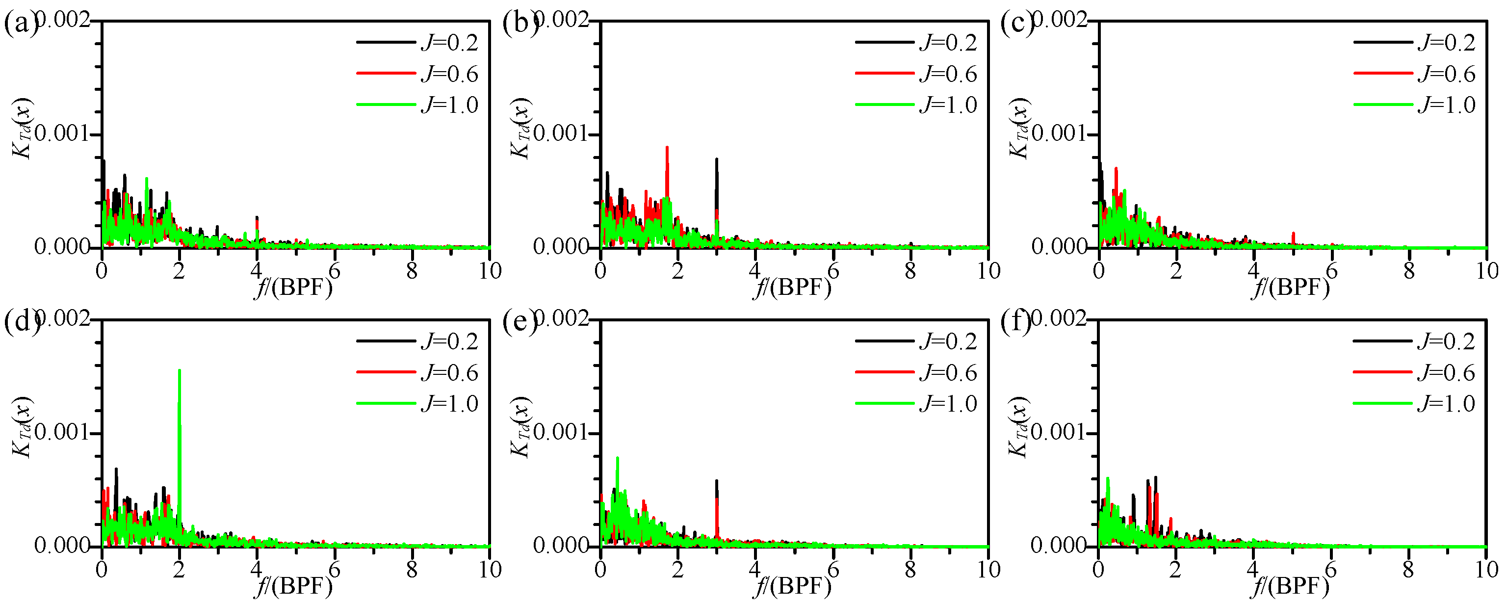
Figure 19.
Pressure distribution on the suction side of a rotor blade. (a) PJP model S8R6, (b) derived PJP models ID 2-7.
Figure 19.
Pressure distribution on the suction side of a rotor blade. (a) PJP model S8R6, (b) derived PJP models ID 2-7.
Figure 20.
Pressure iso-surfaces () in the PJP flow region. (a) PJP model S8R6, (b) derived PJP models ID 2-7.
Figure 20.
Pressure iso-surfaces () in the PJP flow region. (a) PJP model S8R6, (b) derived PJP models ID 2-7.

Figure 21.
Velocity magnitude at slice, where the radii of the dashed circle and the solid circle are and , respectively. (a) PJP model S8R6, (b) derived PJP models ID 2-7.
Figure 21.
Velocity magnitude at slice, where the radii of the dashed circle and the solid circle are and , respectively. (a) PJP model S8R6, (b) derived PJP models ID 2-7.
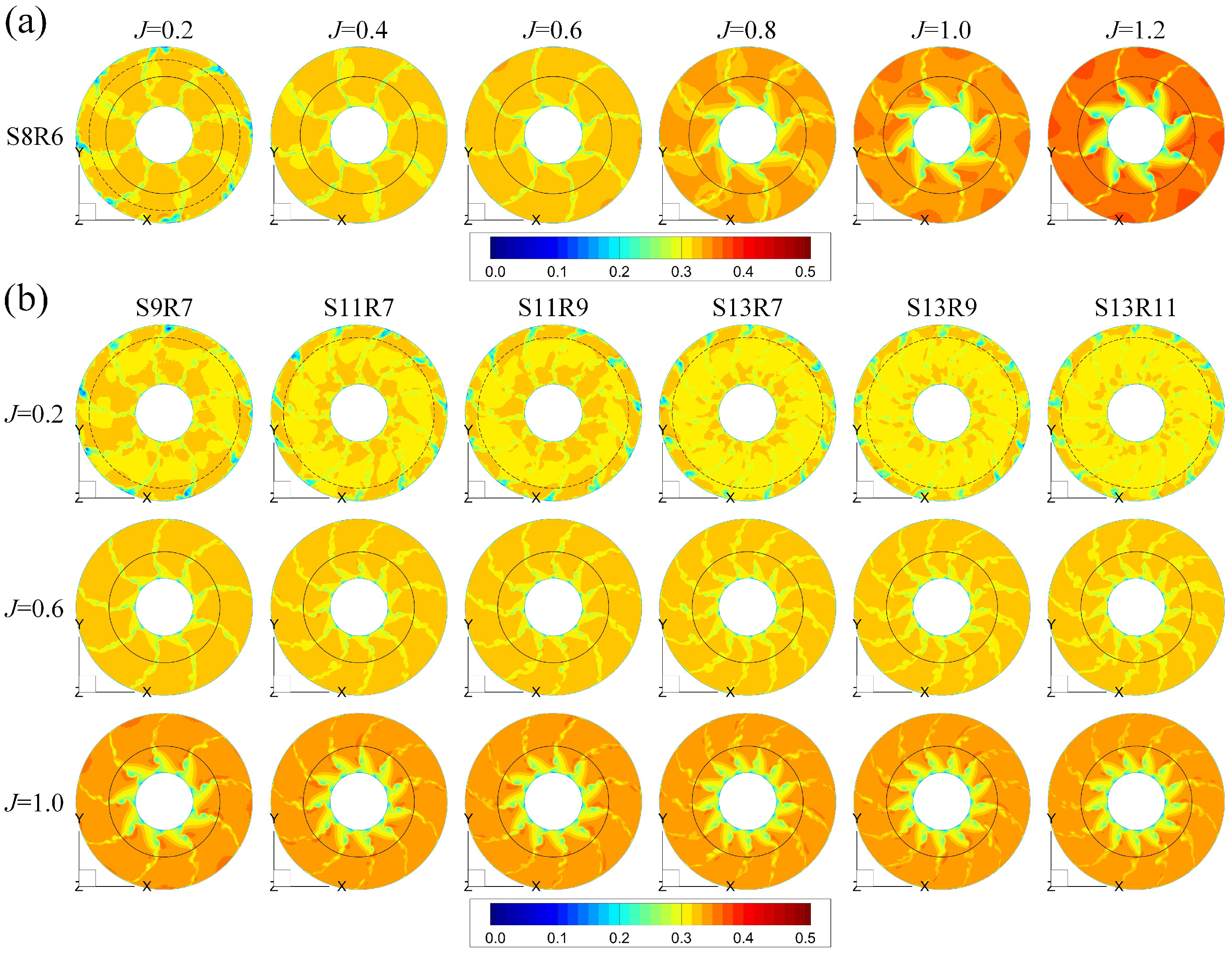
Figure 22.
Velocity magnitude at slice, where the radii of dashed circle and solid circle are and , respectively. (a) PJP model S8R6, (b) derived PJP models ID 2-7.
Figure 22.
Velocity magnitude at slice, where the radii of dashed circle and solid circle are and , respectively. (a) PJP model S8R6, (b) derived PJP models ID 2-7.

Figure 23.
(a) vortices identified by the method in the flow field of PJP model S8R6 at ; (b) back view.
Figure 23.
(a) vortices identified by the method in the flow field of PJP model S8R6 at ; (b) back view.
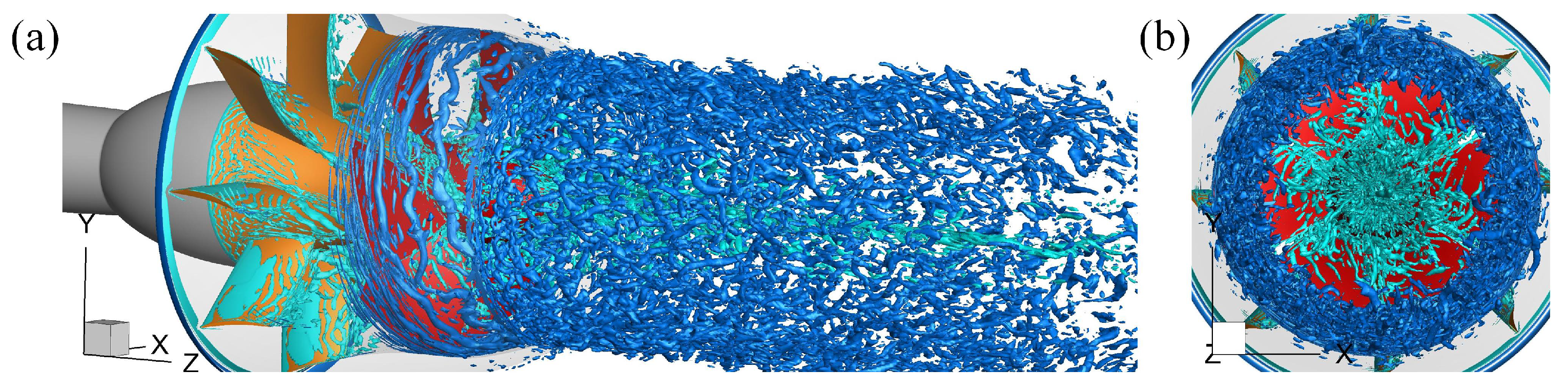
Figure 24.
Interaction between the tip clearance leakage vortex and the duct shed vortex.
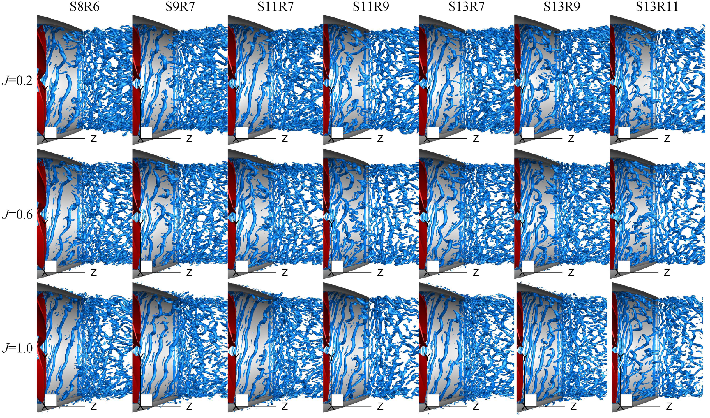
Figure 25.
Interaction between the blade wake vortices of the rotor and stator of PJP model S8R6.
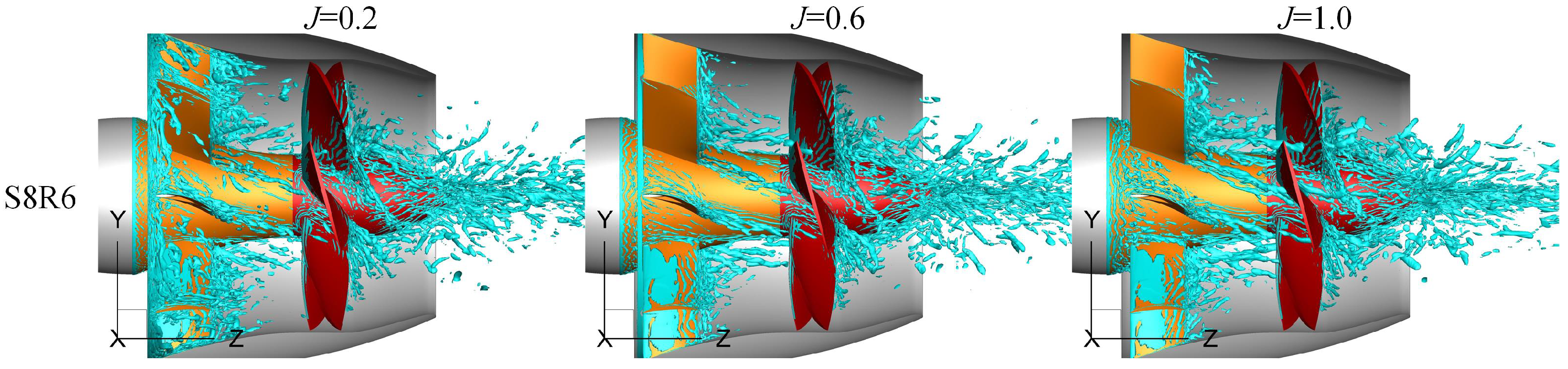
Figure 26.
Interaction between the blade wake vortices of the rotor and stator of PJP models withholding the stator blade numbers: (a) different rotor blade numbers under 11 stator blades, (b) different rotor blade numbers under 13 stator blades.
Figure 26.
Interaction between the blade wake vortices of the rotor and stator of PJP models withholding the stator blade numbers: (a) different rotor blade numbers under 11 stator blades, (b) different rotor blade numbers under 13 stator blades.
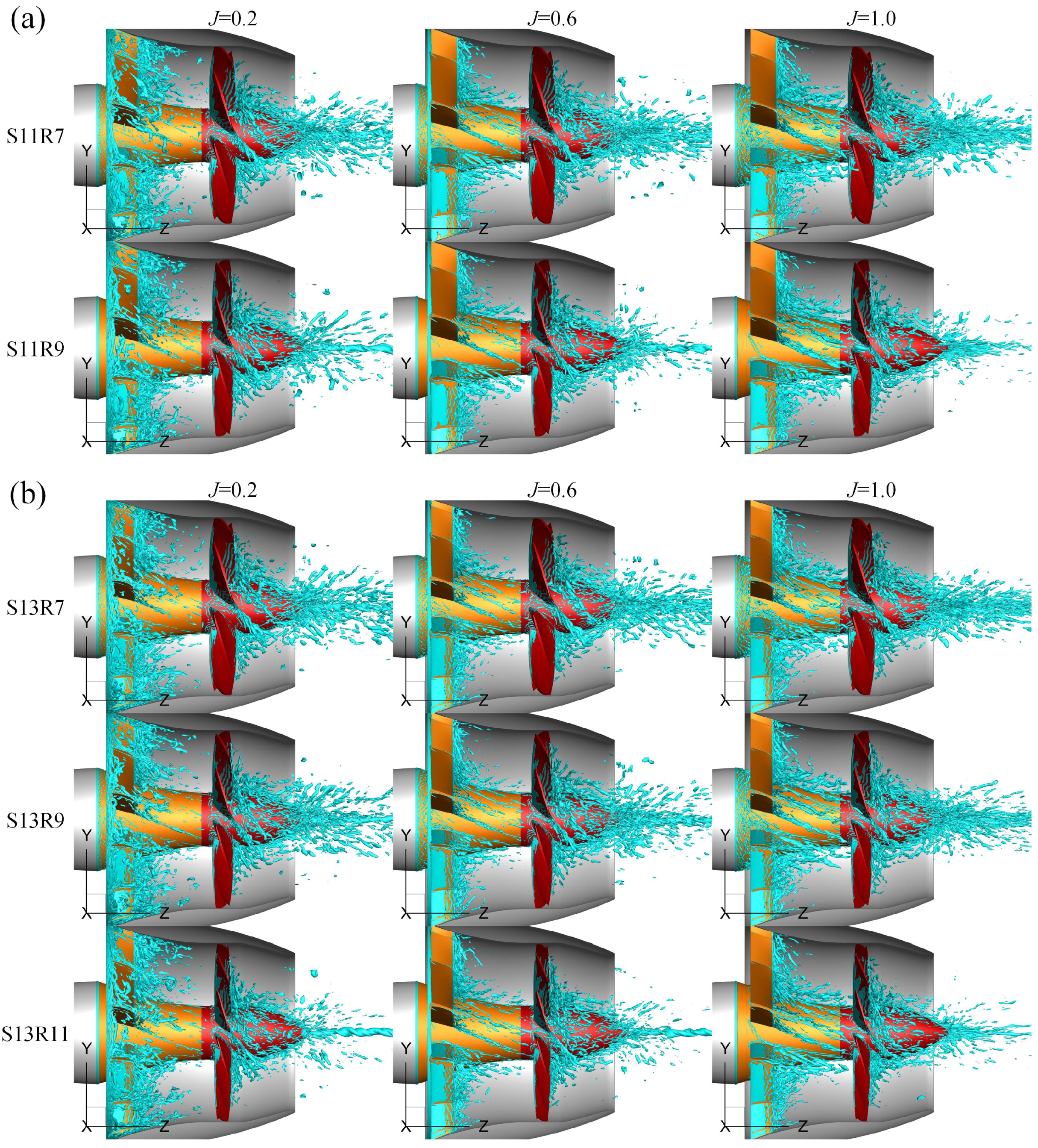
Figure 27.
Interaction between the blade wake vortices of the rotor and stator of PJP models withholding the rotor blade numbers.
Figure 27.
Interaction between the blade wake vortices of the rotor and stator of PJP models withholding the rotor blade numbers.
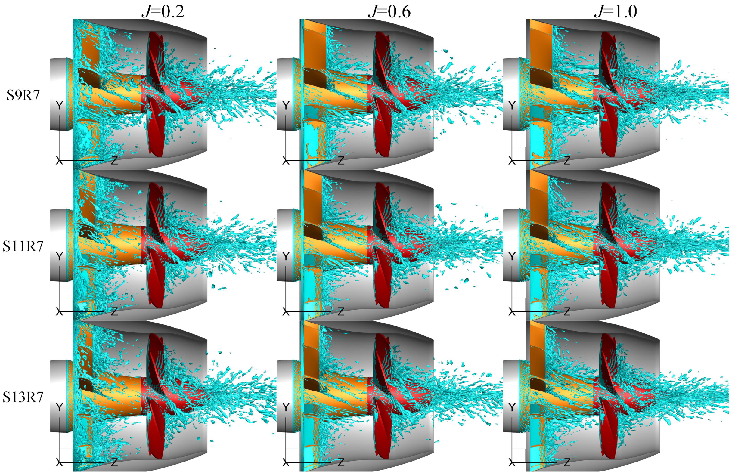
Figure 28.
Hub wake vortices under different rotor and stator blade numbers.

Table 1.
The radial distribution of the stator pre-swirl angle and rotor pitch angle , as shown in Figure 2.
Table 1.
The radial distribution of the stator pre-swirl angle and rotor pitch angle , as shown in Figure 2.
| 0.5 | 0.6 | 0.7 | 0.8 | 0.9 | 1.0 | 1.1 | 1.2 | |
| (rad) | 0.2009 | 0.2716 | 0.3146 | 0.3311 | 0.3246 | 0.2967 | 0.2399 | 0.1705 |
| 0.3 | 0.4 | 0.5 | 0.6 | 0.7 | 0.8 | 0.9 | 1.0 | |
| (rad) | 0.8161 | 0.7061 | 0.6075 | 0.5287 | 0.4649 | 0.4012 | 0.3351 | 0.2658 |
Table 2.
The duct section, where and denote the duct inside and outside the y coordinate.
| 0.000 | 0.0250 | 0.050 | 0.075 | 0.100 | 0.200 | 0.300 | 0.400 | |
| 0.6393 | 0.6156 | 0.6053 | 0.5952 | 0.5866 | 0.5582 | 0.5361 | 0.5182 | |
| 0.6393 | 0.6548 | 0.6567 | 0.6588 | 0.6592 | 0.6561 | 0.6445 | 0.6307 | |
| 0.500 | 0.600 | 0.700 | 0.800 | 0.900 | 1.000 | 1.025 | 1.050 | |
| 0.5076 | 0.5060 | 0.5060 | 0.4990 | 0.4762 | 0.4468 | 0.4421 | 0.4387 | |
| 0.6151 | 0.5978 | 0.5758 | 0.5488 | 0.5168 | 0.4795 | 0.4681 | 0.4582 |
Table 3.
The PJP model with different rotor and stator blade numbers ( and ).
| PJP Model | S8R6 | S9R7 | S11R7 | S11R9 | S13R7 | S13R9 | S13R11 |
|---|---|---|---|---|---|---|---|
| ID | 1 | 2 | 3 | 4 | 5 | 6 | 7 |
| 6 | 7 | 7 | 9 | 7 | 9 | 11 | |
| 8 | 9 | 11 | 11 | 13 | 13 | 13 |
Table 4.
Mesh count (milllions).
| PJP Subdomains | S8R6 | S9R7 | S11R7 | S11R9 | S13R7 | S13R9 | S13R11 |
|---|---|---|---|---|---|---|---|
| rotor | 6.97 | 6.83 | 6.83 | 6.99 | 6.83 | 6.99 | 7.51 |
| stator | 5.73 | 6.14 | 6.76 | 6.76 | 6.96 | 6.96 | 6.96 |
| outer0 | 8.15 | ||||||
| outer1 | 1.89 | ||||||
| outer0 (refined) | 20.63 | ||||||
| outer1 (refined) | 5.70 | ||||||
Publisher’s Note: MDPI stays neutral with regard to jurisdictional claims in published maps and institutional affiliations. |
© 2021 by the authors. Licensee MDPI, Basel, Switzerland. This article is an open access article distributed under the terms and conditions of the Creative Commons Attribution (CC BY) license (https://creativecommons.org/licenses/by/4.0/).
Share and Cite
MDPI and ACS Style
Li, H.; Huang, Q.; Pan, G.; Dong, X.; Li, F. Effects of Blade Number on the Propulsion and Vortical Structures of Pre-Swirl Stator Pump-Jet Propulsors. J. Mar. Sci. Eng. 2021, 9, 1406. https://doi.org/10.3390/jmse9121406
AMA Style
Li H, Huang Q, Pan G, Dong X, Li F. Effects of Blade Number on the Propulsion and Vortical Structures of Pre-Swirl Stator Pump-Jet Propulsors. Journal of Marine Science and Engineering. 2021; 9(12):1406. https://doi.org/10.3390/jmse9121406
Chicago/Turabian StyleLi, Han, Qiaogao Huang, Guang Pan, Xinguo Dong, and Fuzheng Li. 2021. "Effects of Blade Number on the Propulsion and Vortical Structures of Pre-Swirl Stator Pump-Jet Propulsors" Journal of Marine Science and Engineering 9, no. 12: 1406. https://doi.org/10.3390/jmse9121406
Note that from the first issue of 2016, this journal uses article numbers instead of page numbers. See further details here.