
Vertical Stiffness Functions of Rigid Skirted Caissons Supporting Offshore Wind Turbines


1
Arcadis Consulting, London CR0 1EA, UK
2
Department of Civil and Environmental Engineering, University of Surrey, Guildford GU2 7XH, UK
3
Sea & Land Project Engineering, London SE1 1UN, UK
*
Author to whom correspondence should be addressed.
J. Mar. Sci. Eng. 2021, 9(6), 573; https://doi.org/10.3390/jmse9060573
Submission received: 27 April 2021
/
Revised: 17 May 2021
/
Accepted: 18 May 2021
/
Published: 26 May 2021
(This article belongs to the Topic Marine Renewable Energy)
Abstract
:Suction Bucket Jackets (SBJs) need to be fundamentally designed to avoid rocking modes of vibration about the principal axes of the set of foundations and engineered towards sway-bending modes of tower vibration. Whether or not such type of jackets exhibit rocking modes depends on the vertical stiffness of the caissons supporting them. This paper therefore derives closed form solutions for vertical stiffness in three types of ground profiles: linear, homogenous, and parabolic. The expressions are applicable to suction caissons having an aspect ratio (depth: diameter) between 0.2 and 2 (i.e., 0.2 < L/D < 2). The work is based on finite element analysis followed by non-linear regression. The derived expressions are then validated and verified using studies available in literature. Finally, an example problem is taken to demonstrate the application of the methodology whereby fundamental natural frequency of SBJ can be obtained. These formulae can be used for preliminary design and can also be used to verify rigorous finite element analysis during detailed design.
1. Introduction
The European Union’s (EU) strategy to fight climate change and air pollution issues has accelerated the investments into sustainable energy sources. This is essentially to meet the targets of 55% reduction in the greenhouse emissions by 2030 as well as paving the way for climate neutrality by 2050 [1]. Offshore wind in Europe in particular has witnessed a substantial growth, with the UK leading the market (10,428 MW cumulative capacity) and is expected to add 15 GW capacity in the next 5 years. Countries with large offshore wind developments also include Germany (7689 MW capacity), Belgium (2261 MW capacity), and the Netherlands (2611 MW capacity) [2]. Other global leaders include mainland China (approximately 10 GW capacity) [3]. There are new entries to the market including Taiwan (through the Formosa 1 and 2 offshore wind farms) and in the final planning stages for the East Coast of the United States.
This growing demand for renewable energy is responsible for the rapid pace of the technological developments emerging in the industry. Such developments mainly target the turbine size and installations in deeper waters. Wind Europe [2] has stated that the rated capacity of OWT has been enhanced by 102% in the last 20 years. At present, the newly-installed turbines have an average rated capacity of 7.8 MW, though most new installments have turbine capacities exceeding 10 MW. Monopiles support 81% of all installed OWT in Europe [2]. Yet, for some locations, their design poses several engineering challenges and environmental issues to satisfy the requirements needed to support larger wind turbines in deeper waters. This explains the continuous efforts to innovate in this field. Recently, the trend in the construction of new wind farms has considered OWTs supported on jackets as an attractive alternative to conventional monopiles in deeper waters.
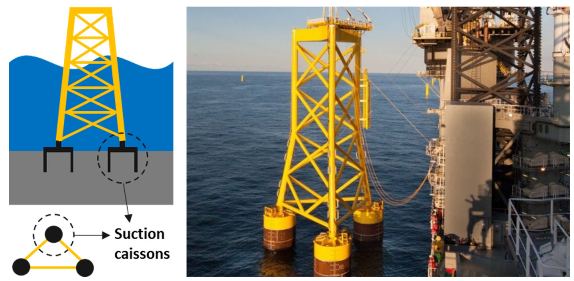
Jackets supported on piles or caissons, illustrated in Figure 1, are suitable for water depths of 30–60 m which allow them to be potentially used for future rounds of wind energy developments [4]. Aberdeen and Borkum Riffgrund 2 offshore wind farms are recent developments utilising caisson jackets foundations to support 8 MW turbines [5]. Other on-going projects include Seagreen and Zhuanghe 2.
There is an inherent difference in the way monopiles and jackets resist overturning moments due to lateral loads. As illustrated in Figure 2, single foundations (typically monopiles) transfer the loads via overturning moments to the surrounding soil. On the other hand, multiple foundations such as jacket on piles/caissons mainly transfer the loads through axial push-pull interaction. This obvious difference will later drive the simple mechanical modelling of the system where the foundation is replaced by equivalent springs for analysis purposes. Hence whilst the lateral stiffness plays a major role in the dynamic performance of monopile supported offshore wind turbines, the vertical stiffness plays a more detrimental role in jackets due to the propensity of rocking type of vibrations. It has shown by Jalbi and Bhattacharya that low-frequency rocking modes of jacket vibration must be avoided as it may coincide with the low frequency 1P rotor frequency and more importantly the peak wave frequency [7].
Current design aims to place the natural frequency of the bottom-fixed structures within the soft-stiff band, see Bhattacharya [4] for fundamentals of design. It is well established in literature that the natural frequency of the system is reliant on the support condition (i.e. foundation stiffness) which in turn is a function of the properties of the foundation and subsoil. Considering the dynamic sensitivity of the OWTs, modes of vibration are considered a key element in the design procedure. Similar to the load transfer process discussed above, the modes of vibration of an OWT system are primarily dependent on the foundation and superstructure stiffness [8].
Studies carried out by Bhattacharya et al. [9] showed that the first eigenfrequency of vibration for OWTs supported on multiple shallow foundations (such as jackets on three or four suction caissons) correspond to low frequency rocking modes of vibration about the principle axes. The work is based on scaled model tests on three types of foundations: monopiles, tetrapods (4-legged jacket on caissons), and asymmetric tripods (3-legged seabed frame on caissons). Rocking modes of vibration are also reported in offshore structures such as the Brent B Condeep platform, see [4].
As mentioned before, rocking modes of vibration tend to have a lower frequency and may interfere with the 1P (rotor) frequency range and wave frequency, see Figure 3 for schematics. This is particularly challenging for large turbines where the soft-stiff target frequency is shifting towards the wave frequency. For example, a typical 8 MW turbine will have a target of 0.22 Hz and a 12 MW turbine will have a target frequency in the range of 0.15 Hz. Furthermore, wave loads will have a higher energy of excitation and may impose serious fatigue damage on the structure if rocking modes are allowed. It is therefore advisable to avoid rocking modes for jackets supported on shallow foundations. In addition, for asymmetric arrangements, scaled model tests showed that they have experienced two closely-spaced natural frequencies associated with the rocking modes of vibration [10]. This corresponds to the variability of the ground reflected in the vertical stiffness of the foundation. Not only does it widen the range of frequencies that can be excited by the loading conditions but also may introduce an additional design problem such as the beating phenomenon and both can have an impact in the fatigue limit state. Moreover, through analytical methods, Jalbi et al. [11] and Jalbi and Bhattacharya [7] showed that that a jacket may be engineered towards a no-rocking solution by optimising two parameters: (a) ratio of vertical stiffness of the foundation stiffness to lateral superstructure stiffness; and (b) aspect ratio of the jacket-tower geometry. A low value of vertical foundation stiffness values together with a low aspect ratio will promote a rocking mode of vibration.
From the discussions above, it is essential to have a method to calculate the vertical stiffness of foundations early on in the design stages of a project. Hence, given the importance of SSI on the dynamic performance, the objectives of the paper are as follows:
- (1)
- Carry out review of the current methods in literature to predict the vertical stiffness of rigid caissons.
- (2)
- Provide static vertical stiffness functions for caissons of aspect ratio between 0.2 and 2 i.e., 0.2 < L/D < 2 for three types of ground: homogeneous, parabolic and linear profiles. This is based on the approach laid out in Eurocodes for ground types (see Eurocode 8 Part 5) and also a gap in the literature.
- (3)
- Demonstrate the application of the developed methodology through a step-by-step solved example in the context of predicting the natural frequency of the system.
It should be noted that the solutions provided in this paper are intended for the concept design stage and for initial sizing of the foundation when information about the structure and the ground profile is scarce. As the design progresses from conceptual to detailed design, a higher computational complexity of the analysis is required to further optimise the foundations. This includes using refined soil constitutive models incorporated in 3D finite element analysis (FEA) packages. In addition, this would also require more input such as site-specific ground investigations and geotechnical laboratory testing.
Background Literature
Ideally, each assessment of the composite system should encompass an independent numerical analysis for the structure and foundation. For instance, the analysis of the latter would likely involve modelling the soil as continuum which is typically carried out using advanced geotechnical finite element methods. However, the limitation of the high computational cost and modelling complexities make it impractical to be utilised in preliminary design stages, yet useful in verifying the final design of the foundation. Consequently, both approaches (i.e., analytical and numerical solutions) tend to idealise the structural dynamics problem through replacing the foundation by a set of lumped springs or in the case of deep foundations distributed springs. The overall stability and foundation stiffness can be purely expressed in terms of functions that describe the force resultants and their conjugate displacements and rotations of these lumped springs. Figure 4 illustrates the breakdown of the structure-foundation problem.
The work of this paper continues the efforts of the research group which aims at providing simplified expressions for the computation of the foundation stiffness. For instance, Shadlou and Bhattacharya [12] studied the lateral dynamic stiffness of deep foundations and proposed spring stiffness functions for both rigid and flexible monopiles. In their model, the foundation is replaced by four springs; KL (lateral spring), KR (rocking spring), KV (vertical spring) and KLR (cross-coupling spring) to capture the degrees of freedom. This methodology was later utilised by Arany et al. [13] in designing monopile foundations. Similarly, Jalbi et al. [14] obtained static stiffness functions for the lateral stiffness terms of a rigid monopod caissons. Moreover, Jalbi and Bhattacharya [15] provided closed form solutions to calculate the natural frequency of jackets supported on multiple foundations incorporating soil-structure interaction (SSI). The foundation flexibility was represented by a set of vertical springs which emphasizes the importance of predicting the vertical stiffness of foundations. Thus, it is now essential to continue the work and obtain the vertical stiffness components of the foundations.
The assessment of static and dynamic vertical spring constants has been the subject of extensive studies in the field of machine foundations and seismic analysis. Most of the elastic solutions available in the literature provide guidance regarding surface and embedded footings. Generally, most literature reports that stiffness decreases with increasing strains and increasing forcing frequencies. However, work on the elastic and non-linear stiffness of a skirted caisson is inadequate. Bell [16] presented a comprehensive review of the existing stiffness coefficients of surface footings, whereas the effect of embedment of the circular footings was extensively discussed in Gazetas [17]. On the other hand, there is less work assessing the stiffness of suction caisson foundations. These foundations are quite similar to the embedded-type foundations with the difference of the soil mass is trapped beneath the lid and within the enclosed volume. Two extreme models could be adopted to represent the caissons: one in which the lid is treated as a rigid circular foundation on the surface while ignoring the effect of the skirts, and another in which the caisson is completely rigid. The latter was analysed by Doherty et al. [18] who provided tabulated coefficients for completely rigid caisson. The analyses incorporated practical variation in soil stiffness, embedment depth and Poisson’s ratios. It also provided correction factors to account for the skirt flexibility. Skau et al. [19] focused on the effect of caisson flexibility following the observations of the extensive behaviour monitoring for Borkum Riffrung 01 -Suction Bucket Jacket (BKR01-SBJ). An elastic correction to the response of a rigid foundation response was suggested to address the foundation flexibility particularly due to the lid which appeared to significantly influence the total vertical stiffness of the system. Table 1 summarises the vertical stiffness formulae found by different researchers for different foundation types including some additional guidance found for deep foundations.
From the table above, it is evident that the available methodologies are limited either by the shape of the footing and the idealised soil profiles which do not reflect the actual heterogeneity in the soil. This paper aims to tackle one aspect of that where solutions are provided for rigid caissons through numerical modelling. The solutions provide the vertical stiffness Kv are for homogeneous, parabolic, and linear ground profiles.
2. Numerical Modelling
Finite element method using Plaxis 3D (continuum approach) was utilised to model the soil-structure interaction. The size of the soil contour is specified such that any stress increase on the boundary is absorbed without rebounding and disturbing the model results. Suryasentana et al. [29] presented a mesh domain of 80D (D is the diameter of the suction caisson) for both diameter and depth to analyse vertically loaded foundations, while Latini et al. [30] used 100D and 30D for the diameter and depth respectively. Moreover, Sloan [31] adopted 5D for the mesh dimensions when analysing vertically loaded rigid circular footing. This clearly shows the wide range of possibilities to eliminate the boundary effects. Considering the scope of this analysis, all the models have been set up with an extent of the soil domain 10D and depth of 15D; as shown in Figure 5 (which has been obtained through trial and error). Despite the symmetry of the problem, a full model was adopted as to avoid a rotation of the caisson if the point load was placed at the centre.
Generally, the stiffness of the foundation dictating the dynamic stability of the system, is characterised by a non-linear nature. It is dependent on the strain levels; generated from the load cycles due to the soil-structure interaction, as well as the forcing frequency (expressed in terms of static and dynamic stiffness) [32]. Since the natural frequency is associated with relatively small amplitude of vibrations (linear range), the initial foundation stiffness would be sufficient for this purpose [13]. Similarly, OWTs are considered a very low frequency application compared to seismic actions based on design charts provided in [12,20,33,34,35,36]. Hence, the effect of the forcing frequency on the stiffness values can be ignored and the static stiffness value can effectively be adopted. Based on the above justifications, the soil is modelled as a linear elastic material. This model is based on Hooke’s law of isotropic elasticity and requires the identification of two basic elastic parameters; Young’s modulus (E) and Poisson’s ratio (vs) which can be determined using conventional site investigation techniques [37].
To encompass the realistic variation of the shear modulus of the soil with depth, three idealisations of the ground profile were adopted:
- Homogenous soil: typical for overconsolidated clays that show constant variation in stiffness with depth and can be easily defined on Plaxis 3D;
- Linear inhomogeneity: common for normally consolidated clay, sometimes referred to as Gibson soil where the stiffness increases linearly with depth [18]; and
- Parabolic inhomogeneity: is an intermediate condition which is typical for sandy soils [12]. Unlike the other two ground profiles, the soil stratum has to be discretised into multiple layers on Plaxis 3D to incorporate the parabolic variation of the soil stiffness. 10 distinct layers of 0.1H thickness each (H is the depth of the soil stratum equivalent to 15D) were used to model the soil stratum. For each layer, an initial stiffness and linear slope were used to mimic the parabolic behaviour.
Figure 6 illustrates the three ground profiles described above where the values of Young’s modulus for the different ground profile intersect at one diameter depth. For all the cases, Poisson’ ratio was assumed to be uniform within each model and the soil density was set to a constant value of 18 kN/m3.
The structure forming the foundation, which consists of the skirt and the lid, has been treated under the assumption of being rigid for all the models. In other words, the response of the foundation system due to the applied loads is solely due to the deformations in the soil (no structural deformations of the caisson lid and skirt). This also includes the soil enclosed within the skirt. This assumption is considered valid considering the low aspect ratio of the caissons modelled and the high flexural and shear stiffness of the steel compared to those of the soil. Doherty et al. [18] investigated the effect of the skirt flexibility on the response of a caisson foundation. Results showed that the vertical stiffness values of both cases are almost similar for low aspect ratios of the caisson which reinforces and validates the previous assumption. In addition, the bucket lid can in-reality deflect and alter the foundation stiffness where the recent in-situ observations by Shonberg et al. [38] confirmed that the suction bucket’s structural elements stiffness has an effect on the performance and can be idealised as pair of vertical springs in series, such that . However, for simplicity, a lumped vertical spring compiling both elements is adopted for this study rather than treating them separately.
Furthermore, the push-pull nature for OWT supported on jackets requires the estimation of the stiffness in both tension and compression, yet this study assumes that the vertical stiffness is the same for both tension and compression as the intention is to use these values for low amplitude vibrations. In reality, the computed compressive stiffness should be higher due to the additional contribution of the bearing below the lid. Other factors should further be investigated involving the impact of the grouted connections and its imperfections, interaction between the adjacent jacketed caissons and imperfect contact at the interface of the soil and foundation. All these factors form a strong basis for the continuation of the work produced in this study. Nevertheless, it may be reminded that the solutions provided in this paper are intended for the concept design stage and for initial sizing of the foundation when information about the structure and the ground profile is limited.
Methodology Verification and Comparison of Results
Normalized values for KV are plotted against L/D for 0.2 < L/D < 2 considering the three different ground profiles. The results are then compared to the solutions provided by Wolf and Deeks [25] and DNVGL [23] which are in turn based on the work of Gazetas [22]. Figure 7 shows the stiffness coefficients plotted for homogeneous profile at two Poisson’s ratios (0.2 and 0.499). All the simulated cases are summarised in Appendix A.1.
The numerical model compares well with the formulations provided in the literature which justifies the method of extraction, the mesh used, the extent of the boundary conditions, and the rigid body assumption applied in the finite element model. Any discrepancy can be justified in terms of the foundation geometry implemented; where both Wolf and Deeks [25] and DNVGL [23] used a solid embedded foundation rather than a skirted caisson with soil mass enclosed within it. Another reason could be the effect of the Poisson ratio.
The impact of Poisson’s ratio on the computed stiffness coefficients was evident from the FE analysis. Therefore, normalised values for the vertical foundation stiffness coefficients in a homogeneous stratum were plotted against υs, as shown in Figure 8. The results were normalised against their respective values at υs = 0.1. The aspect ratio (L/D) also appears to influence the effect of Poisson’s ratio as also shown in Figure 8. For all L/D cases, the stiffness decreases with increasing υs until υs = 0.4 and then slightly increases. Both Gazetas [22] and Wolf and Deeks [25] considered the effect of the soil’s Poisson’s ratio on the stiffness coefficients and incorporated it in their proposed impedance functions. Their proposed functions show similarity with the trend predicted by this study, yet, the impact of the Poisson’s ratio is observed to be slightly lower than the abovementioned literature. Accordingly, a correction factor f(υs), function of both υs and L/D, will be developed in the subsequent section.
3. Development of the Static Stiffness Functions and Correction Factors
Functions for the vertical stiffness were developed using non-linear regression analysis on the normalised set of stiffness coefficients. A diameter of 5m was adopted and the soil stiffness at 1m depth was set as 100 (MPa), see Figure 5. The study then plots the change of the vertical stiffness with increasing L (L values include 2.5, 5, 7.5 and 10 m) and υs (0.1 to 0.49).
First, a new correction factor due to Poisson’s ratio, f(υs), will be presented. The reason for this correction is to clarify how the Poisson’s ratio modifies the vertical stiffness for different ranges of caisson dimensions. Thus, Figure 8 shows that f(υs) is not only a function the Poisson’s ratio itself but also a function of L/D. This has not been extensively discussed in literature where the correction factor was only a function of the Poisson’s ratio itself. Consequently, revised f(υs) functions dependent on both L/D and υs are suggested herein.
From Figure 8, the best fit curve for the Poisson’s ratio correction was a cubic function in the form of . The values of the coefficients a0, a1, a2, and a3 were recorded for L/D = 0.5, 0.75, 1,1.5, 2 normalized at L/D = 0.5. The coefficients for L/D = 0.5 are a0 = 10.028, a1 = -5.8814, a2 = 0.9092, and a3 = 0.96. Figure 9 shows the normalized values for a0, a1, a2, and a3, thus simulating the dependency of f(υs) on L/D. From the figure, it is evident that a0 and a1 follow a similar trend and where given the same logarithmic function whilst a2 followed a different trend and was given another logarithmic function. Finally, a constant value of 1 was given for a3.
As a result, from the analysis above, the Poisson’s ratio correction may be summarized using Equation (1):
It may be noted that the same methodology was repeated in parabolic and linear inhomogeneous ground profiles where the f(υs) obtained was in close proximity to the one shown in Equation (1). Similarly, a few trials on higher aspect ratios (L/D > 2) showed no noticeable change in the formulations:
Subsequently, the normalized values of were then computed and plotted against L/D for all ground profiles. Therefore, a best fit curve was applied in the form of a power function. Even though previous literature did not specifically use power functions for static vertical stiffness functions of shallow caissons, it still performs accurately for the rigid caissons as the R2 values shown show a good correlation as shown in Figure 10 and the solutions are summarized in Table 2.
4. Discussion and Validation of the Results
The functions provided in Table 2 were used to calculate KV for the simulated cases and the highest recorded percentage was found to be below 10% which is considered of low practical significance. The results are also checked against the coefficients provided by [18] and summarized in Table 3. As shown in the table, the results generally show a good match with the obtained results while being applicable for a wide range of Poisson’s ratio. Slight discrepancies exist at the higher Poisson ratio, and this is explained by the difference in the Poisson’s ratio correction between the proposed method and existing literature.
5. Application of the Methodology
In order to demonstrate the application of the proposed vertical stiffness functions, a solved example in the context of the prediction of the natural frequency of an OWT system is presented in this section. A 5 MW turbine supported on a symmetrical four-legged jacket was considered for design in deep waters, as shown in Figure 11. Details about the turbine specification and an approximate jacket dimensions were found in Jonkman et al. [39] and Alati et al. [40], respectively, and summarised in Table 4.
A homogeneous stratum over bedrock is assumed with all the foundation dimensions and soil properties summarised in Table 5.
Using the equations provided in Table 2, a preliminary estimate of the vertical stiffness for a rigid caisson foundation (with L/D = 1) is obtained as shown below:
The target natural frequency of the system for a soft-stiff design should ultimately be between 0.2 and 0.35 Hz to avoid 1P/3P frequencies. Following the methodology suggested by Jalbi and Bhattacharya [15], a closed-form solution of the first natural frequency of the system which considers the soil-structure interaction can be obtained as follows:
where is the fixed base natural frequency and is the foundation flexibility parameter that is dependent on the vertical stiffness of the springs (KV).
For the purpose of this explanatory example, the computed fixed base natural frequency is 0.303 Hz and the CJ is equal to 0.77. Hence, the first natural frequency of the system (with the SSI effect) is calculated to be , refer to Appendix A.2 for the detailed calculation of the example. Although, the estimated value of the natural frequency falls within the targeted range, it is still in close proximity to the 1P frequency.
For further detailed analysis group effects can also be incorporated and readers are referred to Bordón et al. [26] which suggests formulations on how to incorporate foundation group effects correction factors which are dependent on the caisson aspect ratio, diameter and spacing. These formulations are also presented in the Appendix. This will further lower the natural frequency and the design may have to be refined in order to allow for the additional 10% safety margin as per the DNVGL [23] recommendations. Subsequently, the FLS and ULS criteria should also be checked.
6. Conclusions
Offshore wind turbines supported on multiple shallow foundations can exhibit undesirable rocking modes of vibration strongly dependent on the vertical stiffness of the foundation. In this paper, numerical analysis is carried out to explore the axial behaviour of skirted caisson foundations for three idealised ground profiles (homogeneous, linear inhomogeneous and parabolic inhomogeneous) where the soil stiffness varies with depth. A set of static vertical stiffness functions and correction factors due to Poisson’s ratio are derived. The results are validated against numerical and analytical solutions found in the literature. These formulations can be utilised for optimising the caisson’s dimensions for feasibility studies purposes and preliminary design stages of a project. An explanatory example is provided to illustrate the usage of the derived formulation whereby natural frequency of a typical jacket supported OWT structure is calculated.
Author Contributions
Conceptualization, A.S., S.J. and S.B.; methodology, A.S. and S.J.; software, A.S.; validation, A.S. and S.J.; formal analysis, A.S. and S.J.; investigation, A.S. and S.J.; resources, S.B.; data curation, A.S.; writing—original draft preparation, A.S. and S.J.; writing—review and editing, S.B.; visualization, A.S.; supervision, S.B.; project administration, S.B.; funding acquisition, A.S. and S.J. All authors have read and agreed to the published version of the manuscript.
Funding
This research received no external funding.
Institutional Review Board Statement
Not applicable.
Informed Consent Statement
Not applicable.
Data Availability Statement
Not applicable.
Conflicts of Interest
The authors declare no conflict of interest.
Nomenclature
| L | Foundation Depth |
| D | Foundation Diameter |
| R | Foundation Radius |
| Pile | Foundation with L/D > 2 |
| Caisson | Foundation with 0.2 < L/D < 2 |
| ESO | initial soil Young’s modulus at 1D depth |
| ES | Vertical distribution of soil’s Young’s modulus |
| fFB | Fixed base (cantilever) natural frequency |
| CJ | Foundation flexibility parameter |
| mRNA | Mass of Rotor Nacelle assembly |
| mT | Mass of tower |
| DBottom | Tower bottom diameter |
| DTop | Tower top diameter |
| υs | Soil Poisson’s ratio |
| KV | Vertical stiffness of the foundation |
Appendix A
Appendix A.1. Summary of the Analysis Performed

Table A1.
Summary of the Analysis Performed.
| Ground Profiles | ESO (MPa) | L/D (D = 5 m) | υs |
|---|---|---|---|
| Homogeneous Parabolic Inhomogeneous Linear Inhomogeneous | 100 | 0.2, 0.5, 0.75, 1, 1.5, 2 | 0.1, 0.2, 0.3, 0.4, 0.499 |
Appendix A.2. Obtaining the Natural Frequency
Step 1: Calculate the fixed base natural frequency:
This is also presentative of the natural frequency if the jacket is supported on deep embedded piles
Step 2: Calculate CJ for the stiffness of the springs:
Using the equations provided in Table 3, a preliminary estimate of the vertical stiffness for a rigid caisson foundation (with L/D = 1) is obtained as shown below;
Readers are refered to Jalbi and Bhattacharya [15] for the step-by-step derivation of EIT-J and KR. In essence, the vertical spring stiffness was factored by 2 as the method converts the 3D representation of the system into 2D. Therefore, each spring in Figure 11 is representative of two caisson foundations.
Additional Step: Bordón et al. [26] propose the following method to calculate group effects correction factors:
where N is the number of foundations and s is the spacing. For the solved example, this results in reducing the vertical stiffness of the foundations by a factor of 0.63. This further reduces the natural frequency to 0.21 Hz after the repition of the calculation above.
References
- European Commission. 2030 Climate & Energy Framework. 2020. Available online: https://ec.europa.eu/clima/policies/strategies/2030_en#tab-0-0 (accessed on 26 May 2021).
- Wind Europe. The European Offshore Wind Industry. Key Trends and Statistics 2019; windeurope.org: Brussels, Belgium, 2019; Available online: https://windeurope.org/wp-content/uploads/files/about-wind/statistics/WindEurope-Annual-Offshore-Statistics-2019.pdf (accessed on 24 May 2021).
- Global Wind Energy Council. Global Wind Report; Global Wind Energy Council: Brussels, Belgium, 2021. [Google Scholar]
- Bhattacharya, S. Design of Foundations for Offshore Wind Turbines; John Wiley & Sons Ltd.: Chichester, UK, 2019. [Google Scholar]
- 4COffshore Limited. Global Offshore Wind Farms Database. 2021. Available online: http://www.4coffshore.com/windfarms/ (accessed on 15 May 2021).
- Orsted. Our Experience with Suction Bucket Jacket Foundations. 2019. Available online: https://orsted.com/en/our-business/offshore-wind/wind-technology/suction-bucket-jacket-foundations (accessed on 26 May 2021).
- Jalbi, S.; Bhattacharya, S. Minimum foundation size and spacing for jacket supported offshore wind turbines considering dynamic design criteria. Soil Dyn. Earthq. Eng. 2019, 123, 193–204. [Google Scholar] [CrossRef]
- Bhattacharya, S. Civil Engineering Aspects of a Wind Farm and Wind Turbine Structures. In Wind Energy Engineering: A Handbook for Onshore and Offshore Wind Turbines; Elsevier: London, UK, 2017. [Google Scholar]
- Bhattacharya, S.; Nikitas, N.; Garnsey, J.; Alexander, N.; Cox, J.; Lombardi, D.; Wood, D.M.; Nash, D. Observed dynamic soil–structure interaction in scale testing of offshore wind turbine foundations. Soil Dyn. Earthq. Eng. 2013, 54, 47–60. [Google Scholar] [CrossRef]
- Bhattacharya, S.; Cox, J.A.; Lombardi, D.; Wood, D. Dynamics of offshore wind turbines supported on two foundations. Geotech. Eng. 2011, 166, 159–169. [Google Scholar] [CrossRef] [Green Version]
- Jalbi, S.; Nikitas, G.; Bhattacharya, S.; Alexander, N. Dynamic design considerations for offshore wind turbine jackets supported on multiple foundations. Mar. Struct. 2019, 67, 102631. [Google Scholar] [CrossRef]
- Shadlou, M.; Bhattacharya, S. Dynamic stiffness of monopiles supporting offshore wind turbine generators. Soil Dyn. Earthq. Eng. 2016, 88, 15–32. [Google Scholar] [CrossRef]
- Arany, L.; Bhattacharya, S.; Macdonald, J.; Hogan, S.J. Design of monopiles for offshore wind turbines in 10 steps. Soil Dyn. Earthq. Eng. 2017, 92, 126–152. [Google Scholar] [CrossRef] [Green Version]
- Jalbi, S.; Shadlou, M.; Bhattacharya, S. Impedance functions for rigid skirted caissons supporting offshore wind turbines. Ocean Eng. 2018, 150, 21–35. [Google Scholar] [CrossRef]
- Jalbi, S.; Bhattacharya, S. Closed form solution for the first natural frequency of offshore wind turbine jackets supported on multiple foundations incorporating soil-structure interaction. Soil Dyn. Earthq. Eng. 2018, 113, 593–613. [Google Scholar] [CrossRef] [Green Version]
- Bell, R.W. The analysis of offshore foundations subject to combined loading. In Degree of Master of Science; University of Oxford: Oxford, UK, 1991. [Google Scholar]
- Gazetas, G. Formulas and Charts for Impedances of Surface and Embedded Foundations. J. Geotech. Eng. 1991, 117, 1363–1381. [Google Scholar] [CrossRef]
- Doherty, J.; Houlsby, G.; Deeks, A. Stiffness of flexible caisson foundations embedded in nonhomogeneous elastic soil. J. Geotech. Geoenvironmental Eng. 2005, 131, 1498–1508. [Google Scholar] [CrossRef]
- Skau, K.S.; Jostad, H.P.; Eiksund, G.; Sturum, H. Modelling of soil-structure-interaction for flexible caissons for offshore wind turbines. Ocean Eng. 2019, 171, 273–285. [Google Scholar] [CrossRef]
- Lysmer, J. Vertical Motions of Rigid Footings. Ph.D. Thesis, University of Michigan, Ann Arbor, MI, USA, 1965. [Google Scholar]
- Spence, D.A. Self similar solutions to adhesive contact problems with incremental loading. Proc. R. Soc. Lond. Ser. A 1968, 305, 55–80. [Google Scholar]
- Gazetas, G. Analysis of machine foundation vibrations: State of the art. Int. J. Soil Dyn. Earthq. Eng. 1983, 2, 2–42. [Google Scholar] [CrossRef]
- DNVGL. DNVGL-RP-C212 Offshore Soil Mechanics and Geotechnical Engineering; DNVGL AS: Oslo, Norway, 2019. [Google Scholar]
- Wolf, J.P. Soil Structure Interaction Analysis in Time Domain; Electrowatt Engineering Services Ltd.: Zurich, Switzerland, 1988. [Google Scholar]
- Wolf, J.P.; Deeks, A.J. Foundation Vibration Analysis: A Strength-of-Materials Approach; Elsevier: Oxford, UK, 2004. [Google Scholar]
- Bordón, J.D.R.; Aznarez, J.J.; Padron, L.A.; Maeso, O.; Bhattacharya, S. Closed-form stiffnesses of multi-bucket foundations for OWT including group effect correction factors. Mar. Struct. 2019, 65, 326–342. [Google Scholar] [CrossRef]
- Fleming, W.G.; Weltman, A.J.; Randolph, M.F.; Elson, W.K. Piling Engineering; Blackie and Son: London, UK, 1992. [Google Scholar]
- Shama, A.A.; El Naggar, H. Bridge Foundations. Encycl. Earthq. Eng. 2015, 1, 298–317. [Google Scholar]
- Suryasentana, S.; Byrne, B.; Burd, H.; Shonberg, A. Simplified model for stiffness of suction caisson foundations under 6 dof loading. In Proceedings of the SUT OSIG 8th International Conference, London, UK, 12–14 September 2017. [Google Scholar]
- Latini, C.; Cisternino, M.; Zania, V. Vertical dynamic stiffness of offshore foundations. In Proceedings of the 26th International Ocean and Polar Engineering Conference, Rhodes, Greece, 26 June–1 July 2016; pp. 775–780. [Google Scholar]
- Sloan, S.W. Numerical Analysis of Incompressible and Plastic Solids Using Finite Elements. Ph.D. Thesis, Cambridge University, Cambridge, UK, 1981. [Google Scholar]
- Bhattacharya, S.; Wang, L.; Liu, J.; Hong, Y. Civil engineering challenges associated with design of offshore wind turbines with special reference to China. In Wind Energy Engineering: A Handbook for Onshore and Offshore Wind Turbines; Elsevier: London, UK, 2017. [Google Scholar]
- Latini, C.; Zania, V. Vertical dynamic impedance of suction caissons. Soils Found. 2019, 59, 1113–1127. [Google Scholar] [CrossRef]
- Latini, C.; Zania, V. Dynamic lateral response of suction caissons. Soil Dyn. Earthq. Eng. 2017, 100, 59–71. [Google Scholar] [CrossRef] [Green Version]
- Anoyatis, G.; Mylonakis, G.; Lemnitzer, A. Soil reaction to lateral harmonic pile motion. Soil Dyn. Earthq. Eng. 2016, 87, 164–179. [Google Scholar] [CrossRef] [Green Version]
- Lysmer, J.; Udaka, T.; Seed, H.B.; Hwang, R. FLUSH-A Computer Program for Complex Response Analysis of Soft-Structure Systems; University of California: Berkeley, CA, USA, 1974. [Google Scholar]
- Plaxis 3D. Materials Models Manual; Bentley Systems International Limited: Dublin, Ireland, 2018. [Google Scholar]
- Shonberg, A.; Harte, M.; Aghakouchak, A.; Brown, C.S.D.; Andrade, M.P.; Lingaard, M.A. Suction bucket jackets for offshore wind turbines: Applications from in-situ observations. In Proceedings of the TC-209 Workshop—19th ICSMGE, Seoul, Korea, 20 September 2017. [Google Scholar]
- Jonkman, J.; Buttefield, S.; Musial, W.; Scott, G. Definition of a 5-MW Reference Wind Turbine for Offshore System Development; National Renewable Energy Laboratory (NREL): Golden, CO, USA, 2009. [Google Scholar]
- Alati, N.; Failla, G.; Arena, F. Seismic analysis of offshore wind turbines on bottom-fixed support structures. Philos. Trans. R. Soc. A 2015, 373, 20140086. [Google Scholar] [CrossRef] [PubMed]
Figure 1.
Schematic of a 3-legged jacket on suction caissons reproduced from [6], with permission from Ørsted, 2019.
Figure 1.
Schematic of a 3-legged jacket on suction caissons reproduced from [6], with permission from Ørsted, 2019.

Figure 2.
Load transfer in different foundation systems.

Figure 3.
Vibration modes in different foundation systems.

Figure 4.
Breakdown of the structure-foundation problem.

Figure 5.
Mesh dimensions and shape of caissons.

Figure 6.
Variation in stiffness with depth.

Figure 7.
Vertical static stiffness functions for rigid caissons in homogeneous ground profiles at two Poisson’s ratios (A) υs = 0.2, and (B) υs = 0.499.
Figure 7.
Vertical static stiffness functions for rigid caissons in homogeneous ground profiles at two Poisson’s ratios (A) υs = 0.2, and (B) υs = 0.499.

Figure 8.
Variation of vertical stiffness (Kv) with Poisson’s ratio (υs) and aspect ratio (L/D).

Figure 9.
Variation of the polynomial coefficients with L/D.

Figure 10.
Best fit curves for the vertical stiffness functions.


Figure 11.
Example problem.

Table 1.
Methods to estimate the vertical stiffness of the foundation in literature.
| Source (Year) [Reference] | Formulae and Their Applications | |
|---|---|---|
| Surface Foundation | Lysmer (1965) [20] Spence (1968) [21] | Circular rigid footing on surface of homogenous elastic half-space: To account for the roughness of the footing base that allow full transmission of shear stress, Spence [21] proposed the following: The results from this analytical solution showed up to 10% increase in stiffness values at low values |
| Gazetas (1983) [22] DNVGL (2019) [23] | Circular footing on stratum over bedrock: | |
| Gazetas (1991) [17] | Arbitrary shaped foundation on surface of homogenous half-space: where , l is the base-length of the circumscribed rectangle and Ab is the area | |
| Shallow Embedded Foundation | Gazetas (1983) [22] DNVGL (2019) [23] | Circular rigid footing embedded in homogenous stratum over bedrock; Developed for machine-type inertial loading. Range of validity: L/D<1 |
| Wolf (1988) [24] Wolf and Deeks (2004) [25] | General prismatic footing embedded in a linear elastic half space where 2l, 2b are the base dimensions of circumscribed rectangle and e is the embedment depth. This formulation was later simplified by Wolf and Deeks [25]; | |
| Gazetas (1991) [17] | Arbitrary shaped foundation embedded in half-space where is obtained using the equation provided earlier by Gazetas [17]for surface footings, b is the base-width of the circumscribed rectangle, and Aw is the actual sidewall-soil contact area; for constant effective-contact height, d, along the perimeter: Aw = (d) × (perimeter). Based on Gazetas‘ methodology, Bordón et al. [26] developed a simplified formula for the stiffness of a rigid cylinderical foundation embedded in homogenous soil to study the group effect of multi-bucket foundations: | |
| Deep foundation | Fleming et al. (1992) [27] | Embedded piles considering shaft friction only: |
| Shama & El Naggar (2015) [28] | Single pile under axial load for seismic design of highway bridges: |
N.B: KV is vertical stiffness of the foundation, is shear modulus of the soil, is Poisson’s ratio of the medium, D is diameter, L is embedment depth, H is thickness of the soil layer and Ep is modulus of elasticity of pile material.
Table 2.
Vertical stiffness for shallow skirted foundations exhibiting rigid behaviour.
| Ground profile | |
| Homogeneous | |
| Parabolic | |
| Linear |
Table 3.
Comparison of vertical stiffness at υs = 0.2 and υs = 0.499. Data from Doherty et al. (2005) [18].
Table 3.
Comparison of vertical stiffness at υs = 0.2 and υs = 0.499. Data from Doherty et al. (2005) [18].
| Case | υs = 0.2 | Doherty, et al., 2005 [18] | Proposed method | υs = 0.499 | Doherty et al., 2005 [18] | Proposed method |
| L/D = 0.5 Homogeneous | 1.61 | 1.65 | 1.81 | 1.98 | ||
| L/D = 0.5 Linear | 1.38 | 1.00 | 2.10 | 1.199 | ||
| L/D = 2 Homogeneous | 3.29 | 3.146 | 2.86 | 3.21 | ||
| L/D = 2 Linear | 6.72 | 5.47 | 7.60 | 5.58 | ||
| Parameter | Value | Unit |
|---|---|---|
| Height of the jacket (hJ) | 70 | m |
| Jacket bottom width (Lbottom) | 12 | m |
| Jacket top width (Ltop) | 9.5 | m |
| Area of jacket leg (AC) | 0.1281 | m2 |
| Distributed mass of the jacket including diagonals (mJ) | 8150 | kg/m |
| Tower height (hT) | 70 | m |
| Bottom diameter of the tower (Dbottom) | 5.6 | m |
| Top diameter of the tower (Dtop) | 4.0 | m |
| Distributed mass of the tower (mT) | 3730 | kg/m |
| Mass of Rotor-Nacelle Assembly (MRNA) | 350 | tons |
| Mass of transition piece (MTP) | 666 | tons |
Table 5.
Foundation details for the example problem.
| Parameter | Value | Unit |
|---|---|---|
| Foundation depth (L) | 4 | m |
| Foundation diameter (D) | 4 | m |
| Depth to bed rock (H) | 50 | m |
| Soil Young’s modulus (Es) | 40 | MPa |
| Soil Poisson’s ratio (vs) | 0.28 | Non-dimensional |
Publisher’s Note: MDPI stays neutral with regard to jurisdictional claims in published maps and institutional affiliations. |
© 2021 by the authors. Licensee MDPI, Basel, Switzerland. This article is an open access article distributed under the terms and conditions of the Creative Commons Attribution (CC BY) license (https://creativecommons.org/licenses/by/4.0/).
Share and Cite
MDPI and ACS Style
Salem, A.; Jalbi, S.; Bhattacharya, S. Vertical Stiffness Functions of Rigid Skirted Caissons Supporting Offshore Wind Turbines. J. Mar. Sci. Eng. 2021, 9, 573. https://doi.org/10.3390/jmse9060573
AMA Style
Salem A, Jalbi S, Bhattacharya S. Vertical Stiffness Functions of Rigid Skirted Caissons Supporting Offshore Wind Turbines. Journal of Marine Science and Engineering. 2021; 9(6):573. https://doi.org/10.3390/jmse9060573
Chicago/Turabian StyleSalem, AbdelRahman, Saleh Jalbi, and Subhamoy Bhattacharya. 2021. "Vertical Stiffness Functions of Rigid Skirted Caissons Supporting Offshore Wind Turbines" Journal of Marine Science and Engineering 9, no. 6: 573. https://doi.org/10.3390/jmse9060573
Note that from the first issue of 2016, this journal uses article numbers instead of page numbers. See further details here.