
Improvement of the Ship Emergency Response Procedure in Case of Collision Accident Considering Crack Propagation during Salvage Period


Abstract
:1. Introduction
2. Methodology
2.1. Fatigue Crack Propagation in a Damaged Ship
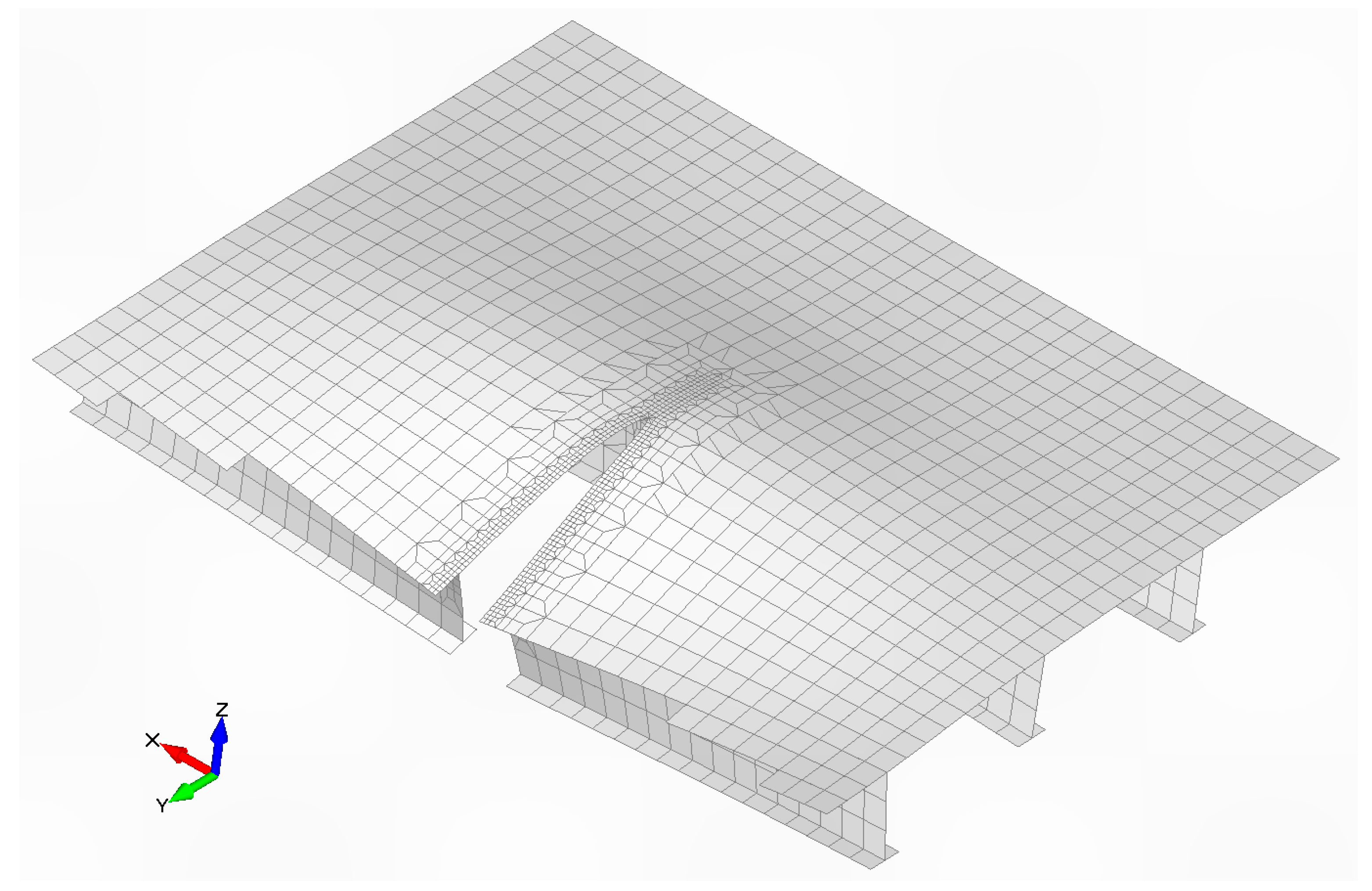
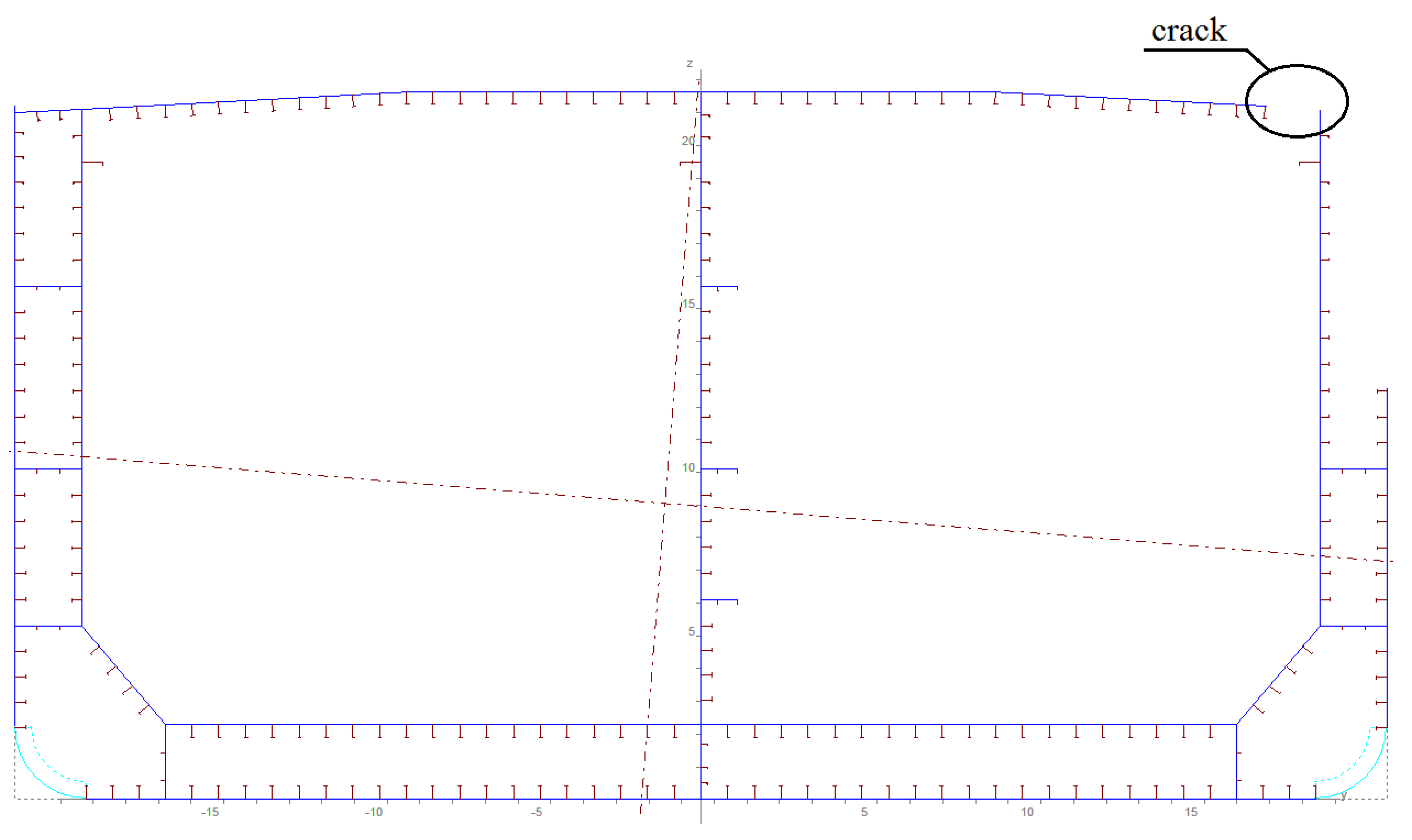
2.2. Modelling of Damaged Ship Structure
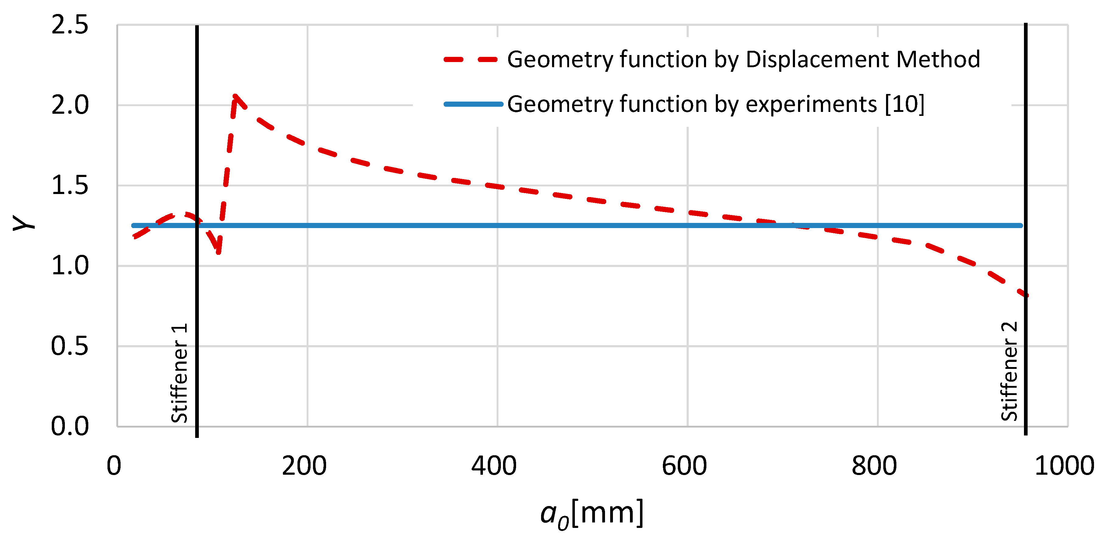
2.3. Computational Methods for Stress Intensity Factor (SIF)
2.4. Monte-Carlo Simulation of Wave-Induced Vertical Bending Moment (VWBM)
2.5. Analysis of Crack Propagation during a Salvage
3. Results
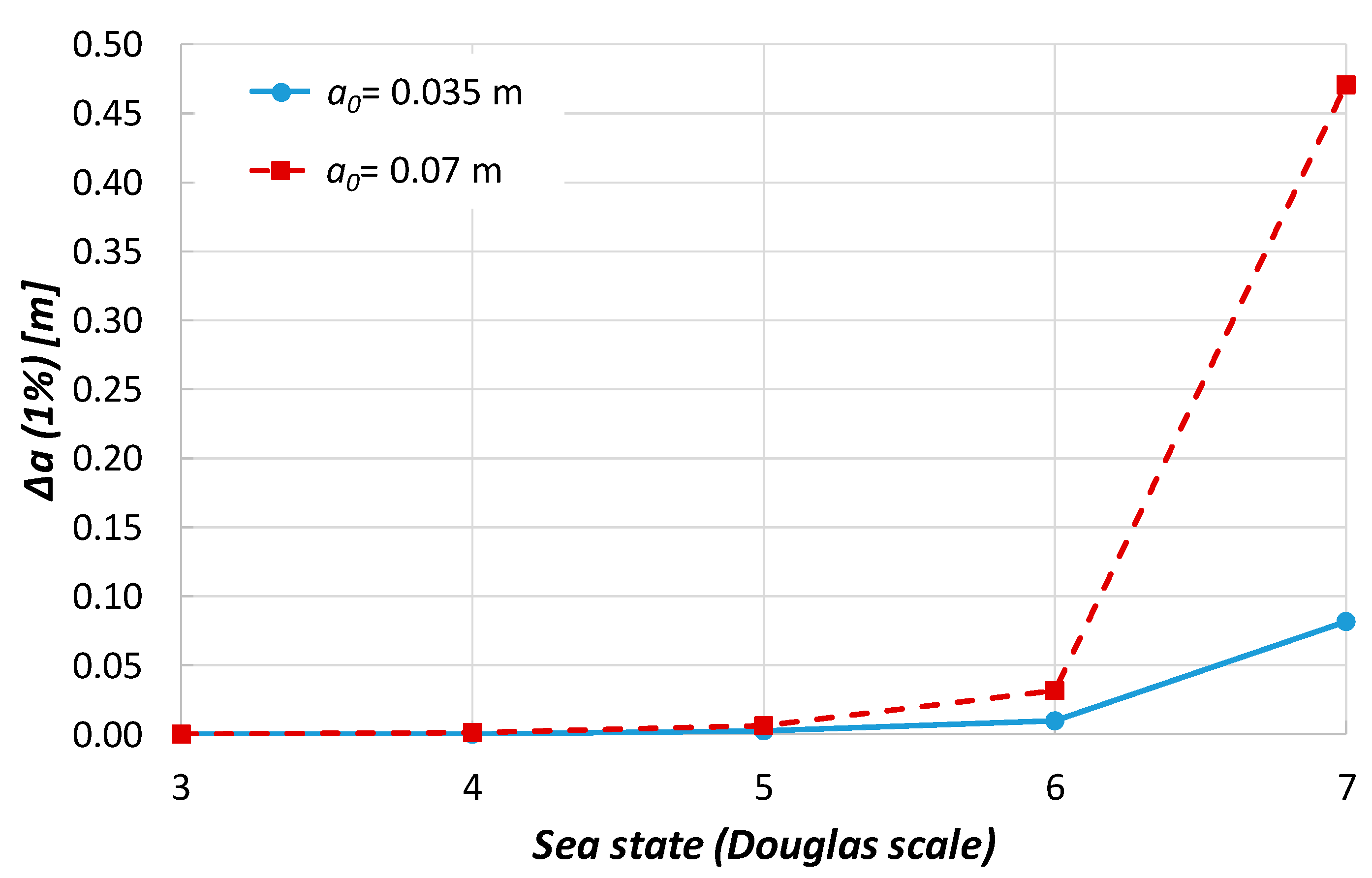
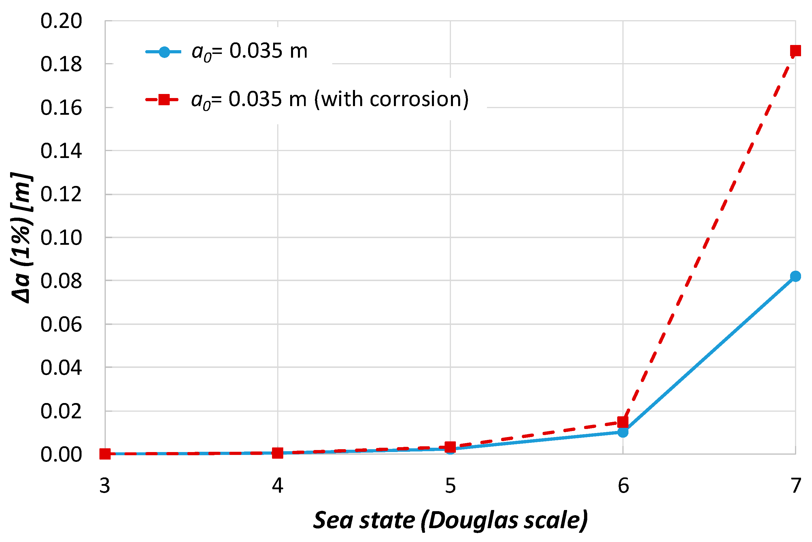
Parametric Analysis
4. Discussion
5. Conclusions
Author Contributions
Funding
Institutional Review Board Statement
Informed Consent Statement
Data Availability Statement
Acknowledgments
Conflicts of Interest
References
- Pedersen, P.T. Marine Structures: Future Trends and the Role of Universities. Engineering 2015, 1, 131–138. [Google Scholar] [CrossRef] [Green Version]
- International Association of Classification Societies (IACS). Limit states. In Common Structural Rules for Bulk Carriers and Oil Tankers (IACS CSR); International Association of Classification Societies: London, UK, 2014. [Google Scholar]
- Wen, F. Rapid response damage assessment. In Marine Technology (mt); Kelly, D., Ed.; SNAME: Alexandria, VA, USA, October 2017; pp. 40–47. Available online: http://sname.digitalwavepublishing.com/ (accessed on 8 June 2021).
- Luis, R.M.; Teixeira, A.P.; Guedes Soares, C. Longitudinal strength reliability of a tanker hull accidentally grounded. Struct. Saf. 2008, 31, 224–233. [Google Scholar] [CrossRef]
- Parunov, J.; Prebeg, P.; Rudan, S. Post-accidental structural reliability of double-hull oil tanker with near realistic collision damage shapes. Ships Offshore Struct. 2020, 15 sup1, S190–S207. [Google Scholar] [CrossRef]
- Gledić, I.; Parunov, J.; Prebeg, P.; Ćorak, M. Low-cycle fatigue of ship hull damaged in collision. Eng. Fail. Anal. 2019, 96, 436–454. [Google Scholar] [CrossRef]
- Kwon, S.; Vassalos, D.; Mermiris, G. Adopting a risk-based design methodology for flooding survivability and structural integrity in collision/grounding accidents. In Proceedings of the 11th International Ship Stability Workshop, Wageningen, The Netherlands, 21–23 June 2010; pp. 1–8. [Google Scholar]
- Sasa, K.; Incecik, A. New Evaluation on ship strength from the view point of stranded casualties in coastal areas under rough water. In Proceedings of the 28th International Conference on Ocean, Offshore and Arctic Engineering (OMAE), Honolulu, HI, USA, 31 May–5 June 2009; pp. 43–50. [Google Scholar]
- Bardetsky, A. Fracture mechanics approach to assess the progressive structural failure of a damaged ship. In Collision and Grounding of Ships and Offshore Structures; Amdahl, J., Ehlers, S., Leira, B.J., Eds.; Taylor & Francis Group: London, UK, 2013; pp. 77–84. [Google Scholar]
- Fricke, W.; Petershagen, H. Fatigue crack propagation in plate panels with welded stiffeners. In Proceedings of the Annual Assembly of International Institute of Welding, Hobart, Australia, July 1988; Volume: IIW-Doc. XIII-1272-88. [Google Scholar]
- Bureau Veritas. Guidelines for Fatigue Assessment of Steel Ships and Offshore Units; Guidance Note NI 611 DT R00 E; Bureau Veritas: Neuilly sur Seine Cedex, France, 2016. [Google Scholar]
- Broek, D. The Practical Use of Fracture Mechanics; Kluwer Academic Publishers: Dordrecht, The Netherlands, 1989; pp. 1–20. [Google Scholar]
- British Standard. Guide to Methods for Assessing the Acceptability of Flaws in Metallic Structures BS 7910; British Standards Institution: London, UK, 2005. [Google Scholar]
- Lützen, M. Ship Collision Damage. Ph.D. Thesis, Department of Mechanical Engineering, Technical University of Denmark, Kgs. Lyngby, Denmark, 2001. [Google Scholar]
- Ringsberg, J.; Amdahl, J.; Chen, B.; Cho, S.; Ehlers, S.; Hu, Z.; Kubiczek, J.M.; Kõrgesaar, M.; Liu, B.; Marinatos, J.N.; et al. MARSTRUCT benchmark study on nonlinear FE simulation of an experiment of an indenter impact with a ship side-shell structure. Mar. Struct. 2018, 59, 142–157. [Google Scholar] [CrossRef] [Green Version]
- Guinea, V.G.; Planas, J.; Elices, M. KI evaluation by the displacement extrapolation technique. Eng. Fract. Mech. 2000, 66, 243–255. [Google Scholar] [CrossRef]
- Carroll, L.B.; Tiku, S.; Dinovitzer, A.S. Rapid Stress Intensity Factor Solution Estimation for Ship Structure Applications (SSC-429); Ship Structure Committee: Washington, DC, USA, 2003. [Google Scholar]
- De Morais, A. Calculation of stress intensity factors by the force method. Eng. Fract. Mech. 2007, 74, 739–750. [Google Scholar] [CrossRef]
- Han, Q.; Wang, Y.; Yin, Y.; Wang, D. Determination of stress intensity factor for mode I fatigue crack based on finite element analysis. Eng. Fract. Mech. 2015, 138, 118–126. [Google Scholar] [CrossRef]
- Laird II, G.; Epstein, S.J. Fracture mechanics and finite element analysis. Mech. Eng. 1992, 114, 69–73. [Google Scholar]
- Dexter, R.J.; Pilarski, P.J. Crack Propagation in Welded Stiffened Panels. J. Constr. Steel Res. 2002, 58, 1081–1102. [Google Scholar] [CrossRef]
- Dexter, R.J.; Mahmoud, H.N.; Pilarski, P. Propagation of Long Cracks in Stiffened Box-sections under Bending and Stiffened Single Panels under Axial Tension. Int. J. Steel Struct. 2005, 5, 181–188. [Google Scholar]
- Rooke, D.P.; Baratta, F.I.; Cartwright, D.J. Simple methods of determining stress intensity factors. Eng. Fract. Mech. 1981, 14, 397–426. [Google Scholar] [CrossRef]
- Jensen, J.J.; Mansour, A.E. Estimation of Ship Long-Term Wave-Induced Bending Moment Using Closed-Form Expressions. R. Inst. Nav. Archit. 2002, W291, 41–55. [Google Scholar]
- Lee, Y.; Chan, H.S.; Pu, Y.; Incecik, A.; Dow, R.S. Global wave loads on damaged ship. Ships Offshore Struct. 2012, 7, 237–268. [Google Scholar] [CrossRef] [Green Version]
- Sun, F.; Pu, Y.; Chan, H.S.; Dow, R.S.; Shahid, M.; Das, P.K. Reliability-Based Performance Assessment of Damaged Ships; Ship Structure Committee Report No. 459; Ship Structure Committee: Washington DC, USA, 2011. [Google Scholar]
- Chen, N.Z. A stop-hole method for marine and offshore structures. Int. J. Fatigue 2016, 88, 49–57. [Google Scholar] [CrossRef] [Green Version]
- MathWorks (Matlab Documentation). Available online: http:/www.mathworks.com/help/index.html (accessed on 8 June 2021).
- MARS. User’s Manual; Bureau Veritas: Paris, France, 2020. [Google Scholar]
- Bužančić Primorac, B.; Ćorak, M.; Parunov, J. Statistics of still water bending moment of damaged ship. In Analysis and Design of Marine Structures; Guedes Soares, C., Shenoi, R.A., Eds.; Taylor and Francis Group: London, UK, 2015; pp. 491–497. [Google Scholar]
- Heinvee, M.; Tabri, K. A simplified method to predict grounding damage of double bottom tankers. Mar. Struct. 2015, 43, 22–43. [Google Scholar] [CrossRef]
- Khan, I.A.; Das, P.K. Reliability Analysis of Intact and Damaged Ships Considering Combined Vertical and Horizontal Bending Moments. Ships Offshore Struct. 2008, 3, 371–384. [Google Scholar] [CrossRef]
- Fujikubo, M.; Zubair, M.A.; Takemura, K.; Iijima, K.; Oka, S. Residual hull girder strength of asymmetrically damaged ships. J. Jpn. Soc. Naval Arch. Ocean Eng. 2012, 16, 131–140. [Google Scholar] [CrossRef] [Green Version]
- Feng, G.Q.; Garbatov, Y.; Guedes Soares, C. Probabilistic model of the growth of correlated cracks in a stiffened panel. Eng. Fract. Mech. 2012, 84, 83–95. [Google Scholar] [CrossRef]
- Paik, J.K.; Wang, G.; Thayamballi, A.K.; Lee, J.M.; Park, Y.I. Time-dependent risk assessment of aging ships accounting for general/pit corrosion, fatigue cracking and local denting damage. Trans. Soc. Nav. Archit. Mar. Eng. 2003, 111, 159–197. [Google Scholar]


| Dimensions | Symbol | Value |
|---|---|---|
| Length between perp. | Lpp [m] | 234 |
| Breadth | B [m] | 40 |
| Depth | D [m] | 21 |
| Draught | T [m] | 14 |
| Deadweight | DWT [t] | 105,000 |
| Vertical Impact Location (XD/D) | Damage Penetration (XB/B) | Striking Ship Length (L) [m] | Striking Ship Depth (D) [m] | Striking Ship Breadth (B) [m] |
|---|---|---|---|---|
| 0.055 | 0.131 | 258.8 | 22.9 | 41.6 |
| Parameter | Value |
|---|---|
| As [m2] | 0.0074 |
| t [m] | 0.0175 |
| bs [m] | 0.85 |
| Sea State | Hs [m] | Tz [m] | nc [cycles] | s [MNm] |
|---|---|---|---|---|
| 3 | 1.25 | 7.5 | 46,080 | 43.9 |
| 4 | 2.5 | 8 | 43,200 | 113.1 |
| 5 | 4 | 8.5 | 40,659 | 199.3 |
| 6 | 6 | 9 | 38,400 | 319.3 |
| 7 | 9 | 10 | 34,560 | 512.2 |
| Parameter | Value |
|---|---|
| Salvage period [days] | 4 |
| C [MPa, m] | 7.27·10−11 [11] |
| m | 3 |
| a0 [m] | 0.035 |
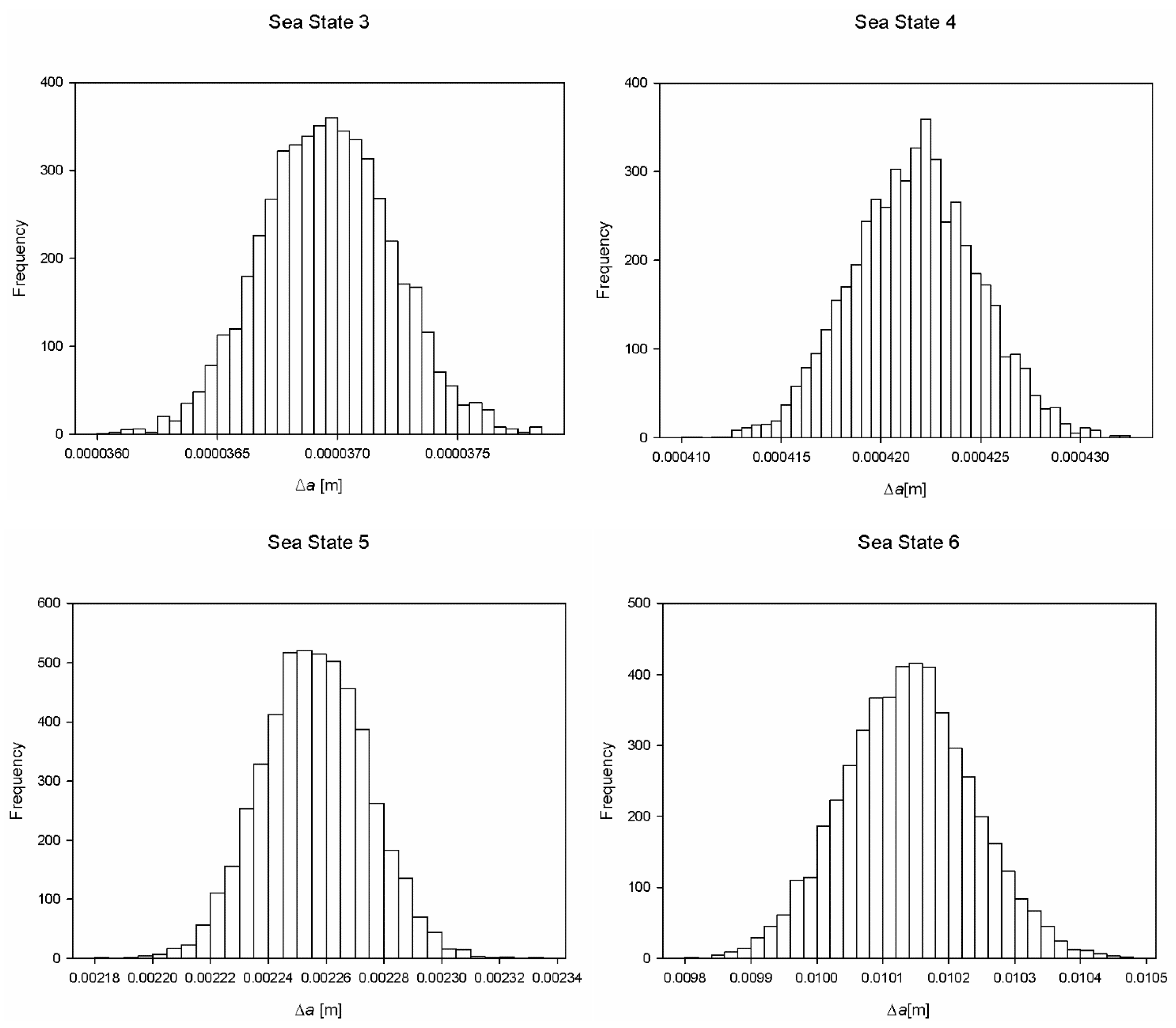
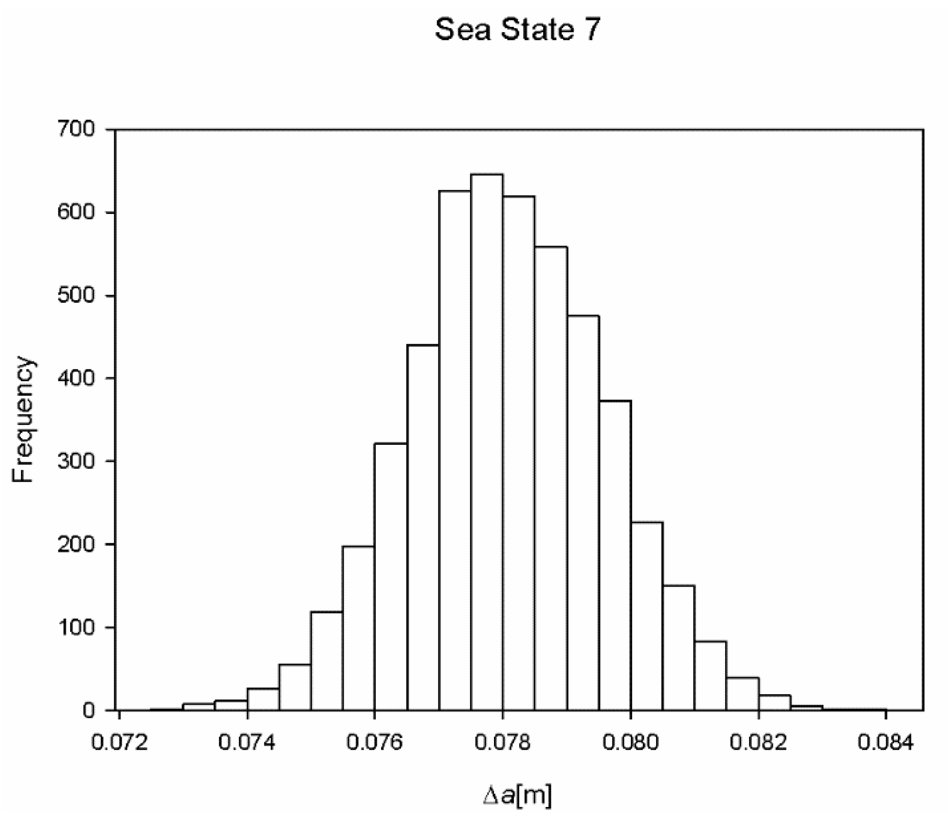
| Sea State | Mean [m] | Standard Deviation [m] |
|---|---|---|
| 3 | 3.7·10−5 | 2.7·10−7 |
| 4 | 4.22·10−4 | 3.13·10−6 |
| 5 | 2.26·10−3 | 1.82·10−5 |
| 6 | 1.0·10−2 | 9.78·10−5 |
| 7 | 7.8·10−2 | 1.53·10−3 |
| Parameter | Value |
|---|---|
| Salvage period [days] | 7 |
| a0 [m] | 0.07 |
| Sea State | nc [cycles] |
|---|---|
| 3 | 80,640 |
| 4 | 75,600 |
| 5 | 71,153 |
| 6 | 67,200 |
| 7 | 60,480 |
| Sea State | as-Built | Corrosion | Increase |
|---|---|---|---|
| Δa (1%) [m] | Δa (1%) [m] | ||
| 3 | 3.77·10−5 | 5.01·10−5 | 33% |
| 4 | 4.29·10−4 | 5.74·10−4 | 33.8% |
| 5 | 2.30·10−3 | 3.11·10−3 | 35.2% |
| 6 | 1.04·10−2 | 1.49·10−2 | 43.6% |
| 7 | 8.21·10−2 | 1.86·10−1 | 126.6% |
Publisher’s Note: MDPI stays neutral with regard to jurisdictional claims in published maps and institutional affiliations. |
© 2021 by the authors. Licensee MDPI, Basel, Switzerland. This article is an open access article distributed under the terms and conditions of the Creative Commons Attribution (CC BY) license (https://creativecommons.org/licenses/by/4.0/).
Share and Cite
Gledić, I.; Mikulić, A.; Parunov, J. Improvement of the Ship Emergency Response Procedure in Case of Collision Accident Considering Crack Propagation during Salvage Period. J. Mar. Sci. Eng. 2021, 9, 737. https://doi.org/10.3390/jmse9070737
Gledić I, Mikulić A, Parunov J. Improvement of the Ship Emergency Response Procedure in Case of Collision Accident Considering Crack Propagation during Salvage Period. Journal of Marine Science and Engineering. 2021; 9(7):737. https://doi.org/10.3390/jmse9070737
Chicago/Turabian StyleGledić, Ivana, Antonio Mikulić, and Joško Parunov. 2021. "Improvement of the Ship Emergency Response Procedure in Case of Collision Accident Considering Crack Propagation during Salvage Period" Journal of Marine Science and Engineering 9, no. 7: 737. https://doi.org/10.3390/jmse9070737