Cooperative Non-Orthogonal Multiple Access with Energy Harvesting

College of Physics and Engineering, Qufu Normal University, Qufu 273165, Shandong, China
*
Author to whom correspondence should be addressed.
Information 2017, 8(3), 111; https://doi.org/10.3390/info8030111
Submission received: 17 July 2017
/
Revised: 7 September 2017
/
Accepted: 12 September 2017
/
Published: 14 September 2017
(This article belongs to the Section Information and Communications Technology)
Abstract
:In this paper, we analyze the outage probability of an amplify-and-forward (AF) cooperative non-orthogonal multiple access (NOMA) model in multi-relay multiuser networks. In contrast to conventional cooperative networks, relays in the considered network have no embedded energy supply; they need to rely on the energy harvested from the signals broadcasted by the source for their cooperative NOMA transmission. Based on this structure, a new relay selection scheme is proposed, considering both channel state information (CSI) and battery status of relays. Assuming each relay has infinite or finite energy storage for accumulating energy, we use the infinite or finite Markov chain to capture the evolution of relay batteries and certain simplified assumptions to reduce computational complexity of the Markov chain analysis. The approximate closed-form expressions for the outage probability of the proposed scheme are derived therefrom. All theoretical results are validated by numerical simulations. The impacts of the system parameters, such as relay number, energy harvesting threshold and battery size, on the performance are extensively investigated.
1. Introduction
With the aim of increasing system capacity and achieving higher spectral efficiency, non-orthogonal multiple access (NOMA) has been recognized as a promising multiple access technique for fifth generation (5G) networks due to its superior spectral efficiency [1].The key idea of NOMA is to serve multiple users in the same frequency band, but with different power levels, which is a domain fundamentally different from conventional orthogonal access technologies [2]. In particular, power-domain NOMA allocates less transmitting power to users with better channel conditions and more transmit power to users with worse channel conditions in order to achieve a balanced tradeoff between system throughput and user fairness. Therefore, users can be separated by successive interference cancellation (SIC). Lan et al. [3] explored the impact of the error propagation of SIC and user velocity on the NOMA performance. Their results showed that, even in the worst error propagation scenario, NOMA outperforms conventional orthogonal multiple access and can yield performance gains for different user mobility. Chen et al. [4] studied NOMA for the downlink of a wireless system. Traditional minimum-mean-squared-error (MMSE) precoding matrices have been used. Considering that wireless relaying is an effective means to combat the effects of the fading and shadowing on transmitted signal, it is reasonable to combine NOMA with relaying networks. In [5], a new cooperative NOMA scheme was proposed and analyzed in terms of outage probability and diversity gain. The authors in [6] study the impact of relay selection on the performance of cooperative NOMA. In particular, a two-stage relay selection strategy is proposed; this strategy can achieve the minimal outage probability among all possible selection schemes, and realize the maximal diversity gain.
In addition to improving spectral efficiency, which is the motivation of NOMA, another key objective of future 5G networks is to maximize energy efficiency. Energy harvesting (EH), a technique to collect energy from the surrounding environment, has recently received considerable attention as a sustainable solution to overcome the bottleneck of energy-constrained wireless sensor networks. Apart from the conventional renewable energy sources, such as solar and wind, radio frequency (RF) signals radiated by ambient transmitters can be treated as a viable new source for EH. Such an approach can reduce the cost of a sensor network, as peripheral equipment can be avoided [7]. However, a fundamental limitation of EH-based wireless communications lies in the restricted transmission range. Although longer ranges can be achieved through a stronger RF source, the available energy level to pick up at the distant receiver remains fairly small due to pathloss. In cellular and sensor networks, relays can be deployed to extend the coverage of base stations [8]. Recently, relays with EH capabilities have received much attention as they use the energy harvested from the source signal to perform information forwarding [9]. This can solve the problem of the energy supply of relays and expand the application of EH-based wireless communications. In [10], a wireless cooperative network is considered in which multiple source-destination pairs communicate with each other via an energy harvesting relay. In [11], both the source and the relay are EH devices and are charged by the destination serving as the power station. In [12], a novel best cooperative mechanism for wireless energy harvesting and spectrum sharing has been proposed, and this mechanism has been verified to be superior to the traditional schemes by simulation. The aforementioned literature concentrates on the achievable performance without considering energy storage at relays; i.e., the harvested energy within a transmission block is entirely consumed for forwarding information. Nevertheless, the energy harvested from RF radiation is often restricted, and thus it is desirable for relays to accumulate the harvested energy in energy storage such as super-capacitors or rechargeable batteries [13]. In [14], a threshold-based “save-then-transmit” scheme is employed at relays; the stored energy level in each relay battery actually forms a Markov chain over time. By investigating the properties of this Markov chain, the asymptotical average throughput is derived. In [15], to support an efficient utilization of harvested energy to improve throughput, a harvest-use-store relaying strategy with distributed beamforming has been researched.
The aforementioned three communication concepts, NOMA, EH and cooperative communication can be combined naturally, which is the focus of this paper. In particular, we consider a NOMA-based downlink amplify-and-forward (AF) relaying network. The main contributions of this paper are summarized as follows:
- (1)
- We design a new NOMA-based relaying network and propose a new EH protocol for relays. The relays have no other energy supplies, but they are equipped with a chargeable battery, and thus can harvest and store the wireless energy broadcasted by the source. Then, we model the capacity of the relay battery in infinite and finite cases, respectively. The outage behavior of the network is investigated, and the closed-form expressions for the outage probability are derived.
- (2)
- Simulation results are conducted to demonstrate our analytical results and the superiority of NOMA. In addition, the impacts of system parameters on the performance of the network are captured by simulation.
- (3)
- Finally, we compared the proposed scheme with a conventional multiple access (MA) cooperative scheme. Simulation results show that, although conventional MA obtains better outage performance than our scheme, our scheme can offer better fairness, since more users are served simultaneously. In addition, our scheme can guarantee acceptable system performance (the best outage probability is 10−5 when transmission signal to noise ratio (SNR)is 20dB) even if the relays do not use their own batteries to power the relay transmission which demonstrates the superiority of our scheme compared to the common cooperative system or common NOMA system.
2. System Model
As shown in Figure 1, a source and a number of potential users communicate over channels with flat fading. Multiple potential relays are willing to amplify and forward the signal from to the users. has no direct link with users. The channels pertaining to the first hop and second hop undergo independent identical (i.i.d.) fading and the channel coefficients are denoted by and , respectively. Assuming Rayleigh fading, is a circularly symmetric complex Gaussian random variable with zero mean and variance . Likewise, . The channel power gain and thus follow the exponential distribution with mean and . Without loss of generality, we assume that the users’ channel gains have been ordered as . We also assume that the additive white Gaussian noise (AWGN) of all links has a zero mean and equal variance .
In this paper, we use the conventional AF protocol for the NOMA downlink cooperative network. From Figure 1, we can see that each transmission block takes two time slots; for convenience but without loss of generality, we consider a normalized unit block time (i.e., ) hereafter, so each time slot takes and the energy harvesting time is also . Before the transmission, each relay checks their battery at the beginning of a transmission block and sees if it has enough energy to forward the source information. If the relay does not have enough energy, it performs EH in this time block and stores the harvested energy into the individual battery. We assume is the transmission power and is sufficiently large such that the energy harvested from the noise is negligible. Thus, the amount of energy harvested from the source can be expressed as [16]
where is the energy harvesting efficiency.
For those relays with sufficient energy, they report their CSI to for making the relay selection decision. Let denote the battery energy amount of relay ; we define those relays with enough energy as the eligible set
where is the energy harvesting threshold to activate the EH circuit and represents the number of times transmit energy over . Among this set of relays, is selected, which can be expressed as
In Equation (3), the relay with the best channel power gain of the first hop in this set is selected for forwarding information.
The two-phase communication starts after relay selection. In the first slot, S transmits the unit-power superposition symbol to the selected , where contains the information required by , is the power allocation coefficient of which denotes the proportion of the transmit power allocated to . Following the principle of NOMA, we have and . The observation at can be expressed as
where is AWGN at . In this time slots, all other relays regard as energy signal and perform EH.
In the second slot, amplifies with an amplifying coefficient and then broadcasts it to all users. The signal received by the nth user can be expressed as
where is the transmit power at relay and , is AWGN at nth user, and should be determined as follows:
For each user, the desired signal is interfered by the other users’ signals. SIC will be carried out at each user to mitigate the negative effect of the inter-user interference. The SIC decoding order is in increasing order of the effective users’ channel gains (). Therefore, at the nth user, the lth user’s signal, , will be detected and then cancelled out from the received signal of the nth user in a successive manner. The lth user’s signal, , will be treated as noise at the nth user. If we set and , then, we can compute the signal to interference and noise ratio (SINR) for the nth user to decode the lth user’s signal, , as follows:
Accordingly, the instantaneous rate can be written as . If the message can be decoded successfully, i.e., , it will be removed from the nth user’s observation, where and denote the target data rate and the target SINR for the lth user, respectively. This SIC will be implemented until n users’ messages are all decoded, where the SINR for the nth user to decode its own signal is given by
The nth user needs to decode all the other users’ signals and the SNR for the nth user to decode its own signal can be expressed as
It is obvious that and . Hence, the achievable data rate for the nth user is given by conditioned on , .
3. Performance Analysis
In this section, the outage performance of the NOMA cooperative network will be characterized in terms of outage probability. According to the total probability law, the outage probability of the nth user can be written as
where denotes the number of elements in a set and is the conditional outage probability when the number of is . We will first study the and then , finally, will be derived.
For ease of description, , , is defined as the outage event where the nth user cannot decode the lth user’s signal successfully, and is defined as the complementary set of . As a result, the conditional outage probability for the nth user can be given by
To proceed forward, we first rewrite as
Next, the other events , , can be attained as
From the final step of Equation (13) we can obtain a necessary condition is:
If the condition is not satisfied, the nth user can never decode the lth user’s signal successfully irrespective of the channel SINR.
By defining , the outage probability for the nth user can be reformulated as
Since follows the exponential distribution with mean , the probability density function (PDF) of can be written as
Similarly, the PDF of the ordered variable is given by
In what follows, and will be addressed. Firstly, according to Equation (16), can be calculated as
On the other hand, by substituting Equations (16) and (17) into , it can be written as
Defining and , can be attained as
Defining and with the aid of Equation (3.478.4) in [17], can be calculated as follows
Until now, we have been able to obtain a conditional exact closed-form expression for the conditional outage probability by substituting Equations (18) and (21) into (15). The next step is to get , which will be given in two cases based on energy storage capacity of relay.
3.1. Infinite Storage of Energy
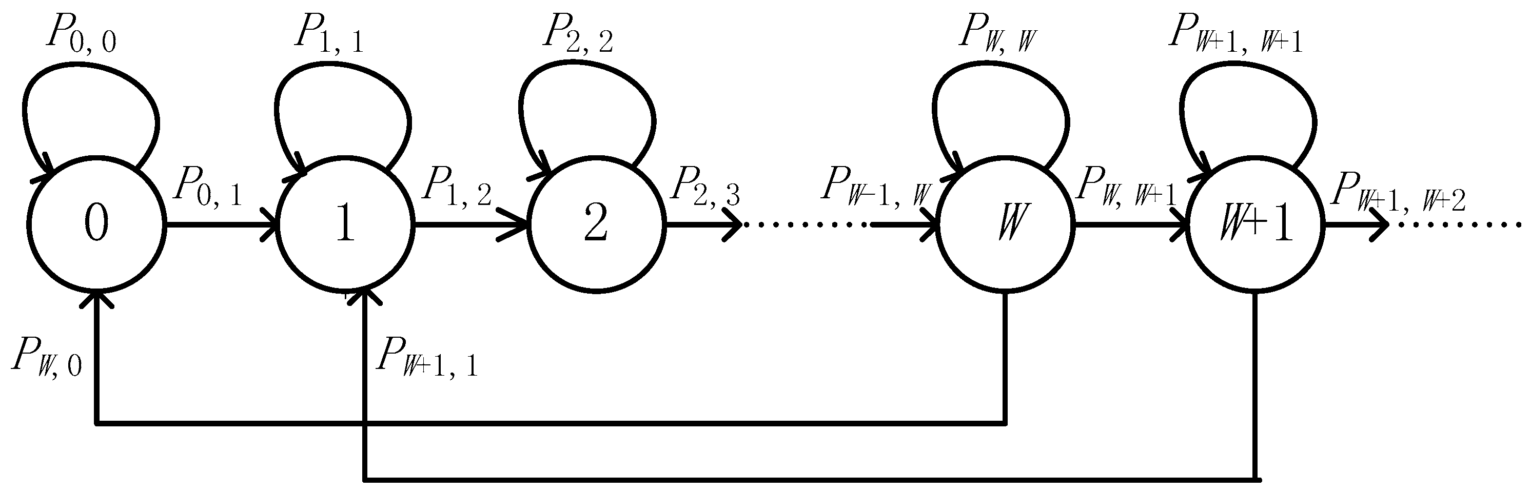
In this case, we assume that each relay has infinite battery and define as the energy harvesting threshold to activate the EH circuit. Although harvested energy can be more than in one time slot, here, we consider each relay to only store and use the rest for its own purpose. The eligible set is composed by relays whose amount of harvested energy are no less than . We model the amount of the stored energy at each relay using an infinite state Markov chain as Figure 2. When the relay does not accumulate enough energy, i.e., the stored energy is smaller than , which corresponds to states in Figure 2, the relay cannot forward the information and there is no transition back to the previous states. When the relay has enough stored energy, i.e., the relay is in state in Figure 2 and is selected as the best relay, its stored energy state transits to state after the relaying.
When , the transition from state to state happens only when the relay harvest no less than amount of energy in one time slot. Hence, using Equation (1), we have
where is the transition probability from state to state . Similarly, the transition from state to state happens when the relay performs EH but the harvested energy is not enough to increase its battery by one level, resulting in
When , the transition from state to state happens when the relay harvest more than amount of energy in one time slot and this relay is not selected at this time slot. We note that the i.i.d. fading assumption implies each relay in has an equal chance to be selected as the best relay, and the average number of relays in is approximately equal to because of infinite storage capacity of relay. We denote as the probability that is selected as the best relay, so . This approximate expression may not always hold; we will discuss the effectiveness of the assumption through numerical results. Using this expression, the corresponding transition probability is given by
Similar to the above case, when , the transition from state to state happens when the relay is not selected and the harvested energy is less than at this time slot. In this case, can be written as
If the relay which is in state is selected as the best relay for transmitting, its harvested energy then transits from state to state . Hence, the transition probability is given by
With the transition probabilities derived in Equations (22)–(26), we form an infinite dimensional transition matrix as (), which can be written as
Let denote the steady state probability vector; then, in the steady state, we have
By expanding Equation (28) and making correspondence on both sides, we notice that
Based on the property of this transition matrix, we have
Then, we have the following relation after some algebraic computation:
Summing all the terms on both side of Equation (32), and using the fact that , we can obtain , . Then, the probability that an relay can be in eligible set, is equal to the probability that the relay is in state , which is given by
With the above result, we can get , which follows the binomial distribution with the probability mass function given as
With and Equation (34), we can get the close form expression of outage probability.
3.2. Finite Storage of Energy
In this case, each relay accumulates the harvested energy using a finite energy storage with the size . We also define as the energy harvesting threshold and is the energy required for forwarding data, but relay can harvest amount of energy in one time slot and is given by
This assumption is closer to the practical scenario, and the evolution of the battery status of all relays can be modeled as a finite state Markov chain; using the transition probability matrix of this chain, we can get the steady state probability vector and . Once is obtained, the outage probability can also be obtained.
Due to the lack of general form of steady state probability, the above analysis is computationally intense when is large. To facilitate the computation, we propose an approximated approach based on two simplified assumptions. Firstly, we denote the relay energy amount at the selection epoch as a random variable . The exact distribution of is high computational complexity. To ease the computation, we approximate by a uniform random variable over . The adopted approximation is inspired by considering the amount of harvested energy in a transmission block follows the geometric distribution with parameter 1/2 [18]. In general, these conditions may not always hold. We will discuss the effectiveness of the assumption through numerical results. Secondly, we found that an arbitrary relay may be either short of enough power to participate in relay selection or otherwise, so the evolution of relay energy amount is captured by using two states, either active or inactive. With this simplified two-state Markov chain, a relay is in if the relay lacked sufficient energy to transmit, or in when the relay has enough energy for transmission. Next, we explain how to obtain the transition probability matrix of the two-state Markov chain.
The transition from state to state happens when a relay has no enough energy to transmit (i.e., ) in the current block and the accumulated energy after harvesting remains below . The corresponding transition probability is given by
where is a truncated random variable defined as
Since is approximated as uniformly distributed, the PDF of can be obtained as
where and denote the unit step function and the Dirac delta function, respectively. Then Equation (36) can be solved as
where .
The transition from to happens when the relay enters the EH mode in the current bock and the accumulated energy exceeds . Hence, we have
Similar to the derivation of Equation (36), we obtain
If the relay which is in state is selected as the best relay for transmitting, its harvested energy then transits from state to state . Hence, the transition probability is given by
where is a truncated random variable defined as
Since is uniformly distributed, the PDF of can be obtained as
Using this PDF, the first term in the right of Equation (42) can be obtained as
As to the second term, we note that the i.i.d. fading assumption implies each relay in has an equal chance to be selected as the best relay. To simplify the analysis, we approximate the cardinality of by its mean such that
where is the average number of relays in and is the steady-state probability of state . Combining Equations (45) and (46), we can obtain the closed-form for .
The transition probability from to can be solved in the similar manner as the previous case, so we omit the derivation here.
When the two-state Markov chain formulated, the steady state probability vector can be easily obtained as
We note that both and involve , which is a function of . By substituting and into Equation (47), can be solved explicitly. Take the condition in Equation (45), for example; can be obtained in closed form as
With at hand, we can get , which follows the binomial distribution with the probability mass function given as
Submitting into Equation (10), we can get outage probability of the system.
4. Simulation Results
In this section, computer simulations are performed to validate the mentioned theoretical analysis. In all simulations, we set the noise power to , the energy harvesting efficiency to , and the fixed transmission rate of the source is 1 bit per channel use (bpcu). The battery size is set to be a multiple of the energy harvesting threshold , i.e., , where and . We also set is the multiple of the source transmission energy, i.e., , where is the scaling factor and the length of a transmission block . To facilitate the analysis, and are set to be 1. Without loss of generality, we set , the power allocation coefficient are , and , the outage threshold are = 0.9 dB, = 1.5 dB and = 2 dB.
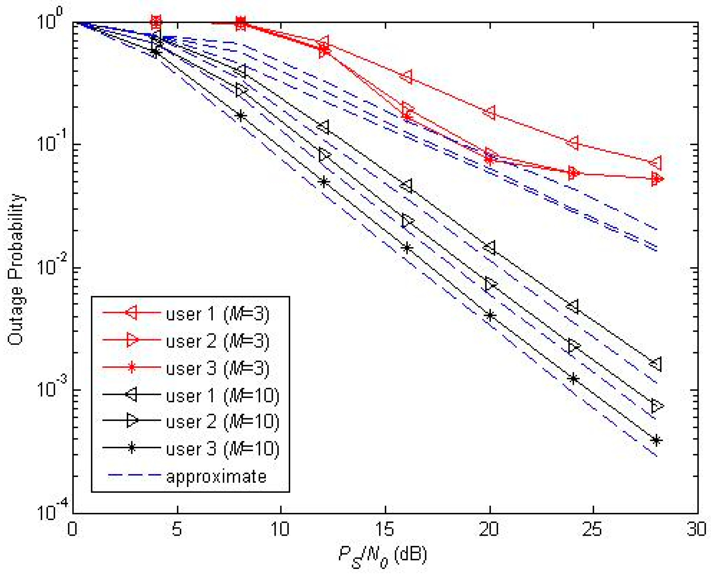
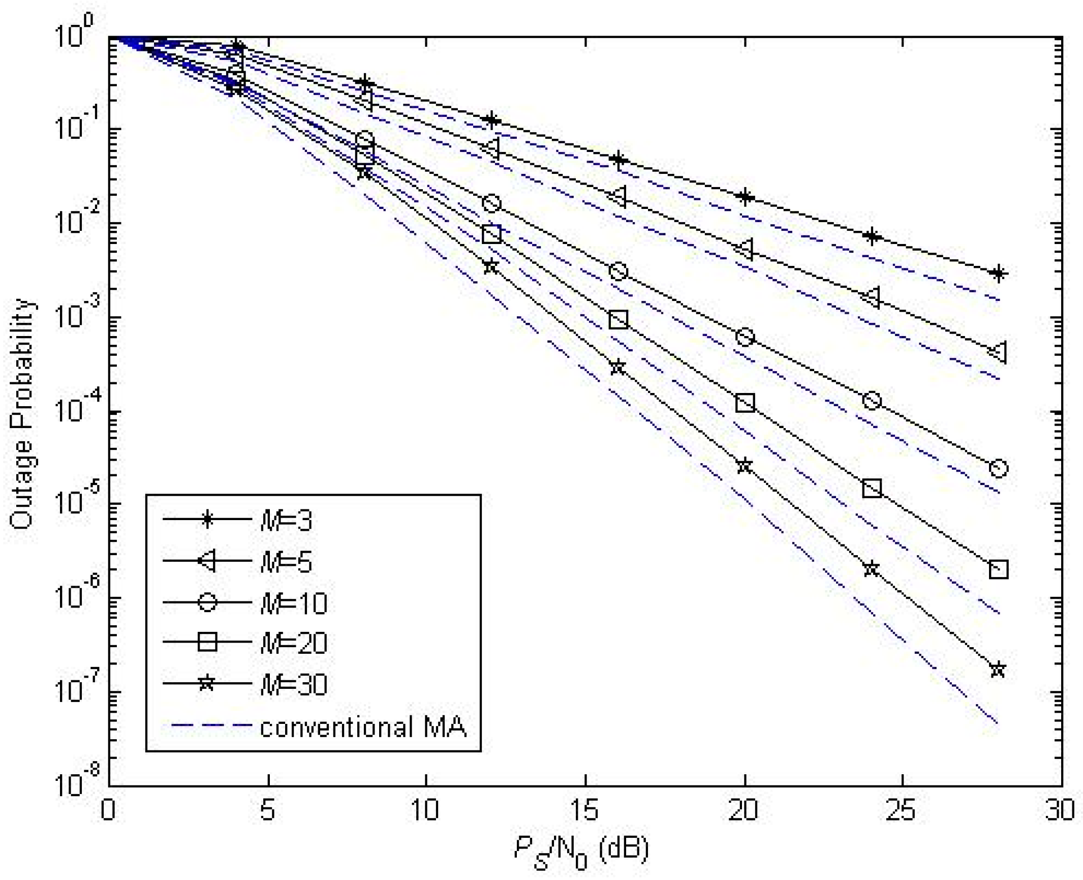
Figure 3 and Figure 4 illustrate the performance of the proposed protocol with infinite battery size and finite battery size versus the transmitting SNR of source for given values of and , respectively. We set and . In Figure 3 and Figure 4, the approximated analysis of infinite and finite Markov chain is accurate when the number of relays is sufficient, but its results become deviated from the simulated ones for . The outage probability reveals an error floor when . This is because, when , relays cannot maintain a enough energy state in the infinite storage case, and the energy distribution of the relay battery is no longer as uniform as assumed in the finite storage case, respectively. However, when increases, the approximate cardinality of becomes more accurate. We can also see that the slope of the outage probability curve (namely, diversity order) increases with . Since the theoretical analyses agree well with the simulations in medium and high SNR ranges, we will only plot the analytical results in the remaining figures.
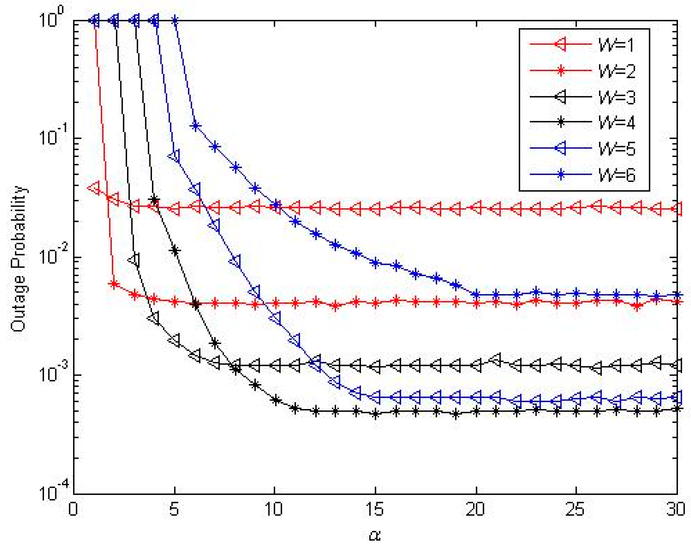
Next, we will investigate the impacts of the system parameters on the performance in medium SNR conditions (). In Figure 5 and Figure 6, we illustrate the impacts of on the performance of the proposed two battery scheme with different . is set in both two figures. For all the curves in Figure 5 and Figure 6, the trends are the same for all schemes; namely, the probability first decreases then increases as varies from 0 to 1. This means that, when the other parameters are determined, there must be an optimal value of . However, the values of the inflection points are not always the same for different users and are inversely proportional to . When , the eligible set has more relays than ; the probability of choosing the best relay with more energy is larger than , and so the optimal value of can be greater than . The optimal value of can easily be obtained by a one-dimensional exhaustive search; with this optimal value of , the system can resist fading more effectively.
In Figure 7, we investigate the impact of battery size on the proposed finite battery scheme by varying the battery scaling factor with fixed number of relay (). Since three users have the same trend, we only analyze user 3 in this figure. From Figure 7, we can observe that the performance increases as increases. However, the gain provided by a larger battery size does not increase when exceeds a certain value and this value is decided by . From this figure, we can also see that the order of performance for different changes when the value of changes.
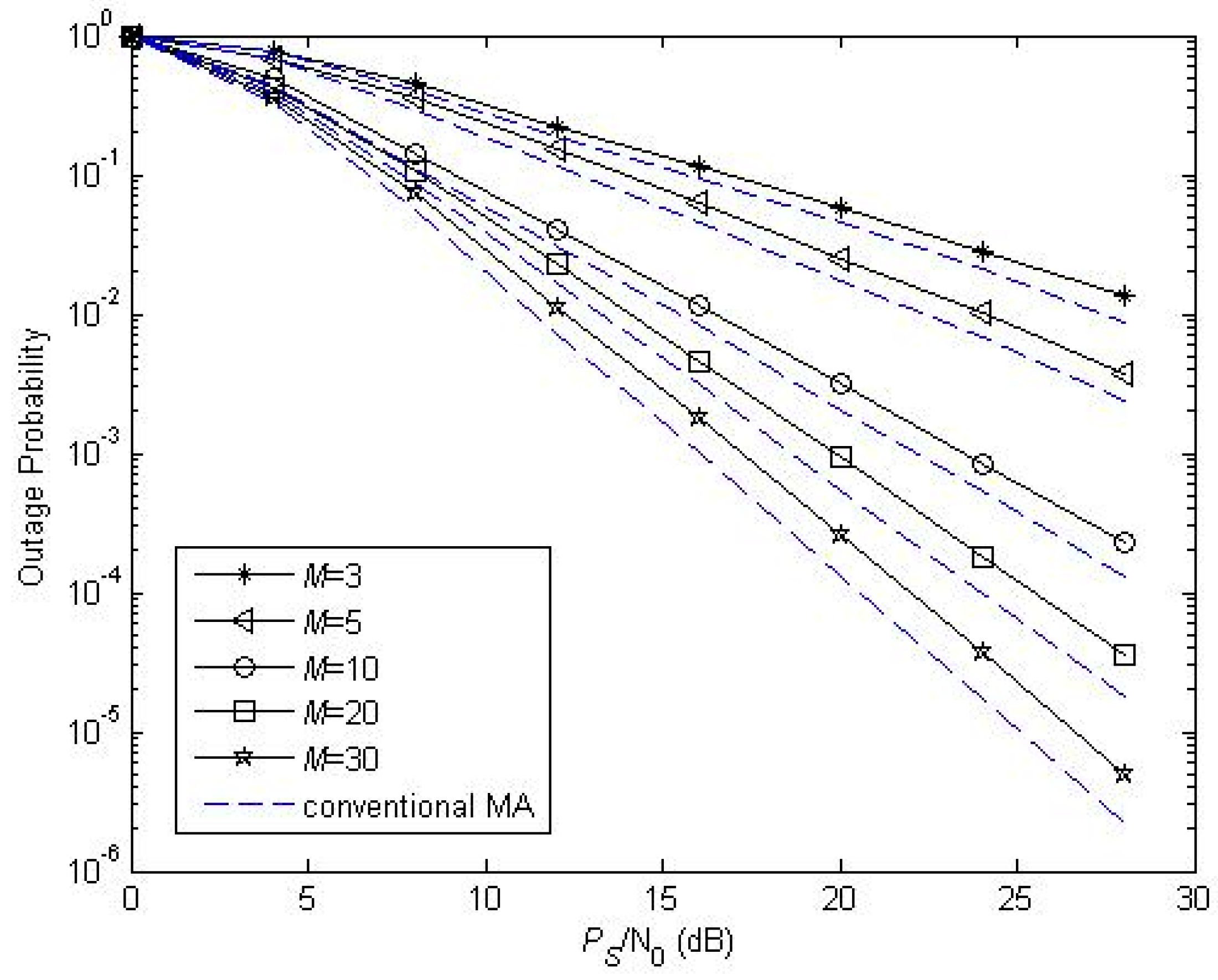
Figure 8 and Figure 9 illustrate the performance of the proposed protocol for different relay number. We also only analyze user 3 in both two figures. and are set. In order to illustrate the scalability of our algorithm, we set , , , and , respectively. From those two figures, we can see that, when is small, there is a huge drop of outage probability with a slight increase of ; this is because relays in the eligible set are insufficient when is small, and the slight increase of will increase the number of relays in the eligible set remarkably and a better relay can be selected. However, when is huge ( or ), relays in the eligible set are sufficient, and the increase of enhances the performance slightly, thus our algorithm can be used when is not more than 10. In addition, we compared the proposed scheme with conventional MA cooperative scheme. Here, we assume that an opportunistic MA approach is adopted for conventional MA, where the user with the best channel condition is scheduled. The target SINR for conventional scheme satisfies Simulation results show that conventional MA can achieve the same diversity gain with user 3. Conventional MA obtains better outage performance than NOMA, but NOMA can offer better fairness since more users are served simultaneously.
5. Conclusions
In this paper, we analyze the performance of the cooperative NOMA network. A new relay selection scheme is proposed considering both CSI and battery status of relays. We model the amount of harvested energy at each relay using an infinite or finite Markov chain and then derive the approximate closed-form expression of the outage probability in two cases, respectively. Simulations are carried out to verify the correctness of the theoretical analysis. We conclude the superiority of NOMA and find that, by carefully choosing the parameters of the network, (e.g., energy harvesting threshold or forwarding threshold), acceptable system performance can be guaranteed even if the relays do not use their own batteries to power the relay transmission. For future work, we will investigate the performance of cooperative NOMA in large-scale relaying networks using stochastic geometry.
Acknowledgments
This work was supported by the Scientific Research Initial Fund of Qufu Normal University (No. BSQD2012055), Youth Fund of Qufu Normal University (No. xkj201306) and Project of Shandong Province Higher Educational Science and Technology Program (No. J15LN57).
Author Contributions
Weidong Guo conceived of the idea. He developed the mathematical models and performed the Monte Carlo simulations. Yunfeng Wang checked the mathematical model and the simulated results.
Conflicts of Interest
The authors declare no conflict of interest.
References
- Saito, Y.; Benjebbour, A.; Kishiyama, Y.; Nakamura, T. System level performance evaluation of downlink non-orthogonal multiple access (NOMA). In Proceedings of the IEEE Annual International Symposium on Personal, In door and Mobile Radio Communications (PIMRC), London, UK, 8–11 September 2013; pp. 611–615. [Google Scholar]
- Ding, Z.; Yang, Z.; Fan, P.; Poor, H.V. On the performance of non-orthogonal multiple access in 5G systems with randomly deployed users. IEEE Signal Process. Lett. 2014, 21, 1501–1505. [Google Scholar] [CrossRef]
- Lan, Y.; Benjebboiu, A.; Chen, X.; Li, A.; Jiang, H. Considerations on downlink non-orthogonal multiple access (NOMA) combined with closed-loop SU-MIMO. In Proceedings of the IEEE International Conference on Signal Process and Communication System (ICSPCS), Gold Coast, Australia, 15–17 December 2014; pp. 1–5. [Google Scholar]
- Chen, X.; Benjebbour, A.; Lan, Y.; Li, A.; Jiang, H. Impact of rank optimization on downlink non-orthogonal multiple access (NOMA)with SU-MIMO. In Proceedings of the IEEE International Conference on Communication System (ICCS), Macau, China, 19–21 November 2014; pp. 233–237. [Google Scholar]
- Ding, Z.; Peng, M.; Poor, H.V. Cooperative non-orthogonal multiple access in 5G systems. IEEE Commun. Lett. 2015, 19, 1462–1465. [Google Scholar] [CrossRef]
- Ding, Z.; Dai, H.; Poor, H.V. Relay selection for cooperative NOMA. IEEE Wirel. Commun. Lett. 2016, 5, 416–419. [Google Scholar] [CrossRef]
- Liu, L.; Zhang, R.; Chua, K.C. Wireless information transfer with opportunistic energy harvesting. IEEE Trans. Wirel. Commun. 2013, 12, 288–300. [Google Scholar] [CrossRef]
- Scaglione, A.; Goeckel, D.L.; Laneman, J.N. Cooperative communications in mobile ad hoc networks. IEEE Signal Process. Mag. 2006, 23, 18–29. [Google Scholar] [CrossRef]
- Nasir, A.A.; Zhou, X.; Durrani, S.; Kennedy, R.A. Relaying protocols for wireless energy harvesting and information processing. IEEE Trans. Wirel. Commun. 2013, 12, 3622–3636. [Google Scholar] [CrossRef]
- Ding, Z.; Perlaza, S.M.; Esnaola, I.; Poor, H.V. Power allocation strategies in energy harvesting wireless cooperative networks. IEEE Trans. Wirel. Commun. 2014, 13, 846–860. [Google Scholar] [CrossRef]
- Chen, H.; Li, Y.; Rebelatto, J.L.; Uchôa-Filho, B.F.; Vucetic, B. Harvest-then-cooperate: Wireless-powered cooperative communications. IEEE Trans. Signal Process. 2015, 63, 1700–1711. [Google Scholar] [CrossRef]
- Gao, H.; Ejaz, W.; Jo, M. Cooperative Wireless Energy Harvesting and Spectrum Sharing in 5G Networks. IEEE Access 2016, 4, 3647–3658. [Google Scholar] [CrossRef]
- Sudevalayam, S.; Kulkarni, P. Energy harvesting sensor nodes: Survey and implications. IEEE Commun. Surv. Tutor. 2011, 13, 443–461. [Google Scholar] [CrossRef]
- Huang, C.; Zhang, J.; Zhang, P.; Cui, S. Threshold-based transmissions for large relay networks powered by renewable energy. In Proceedings of the IEEE Global Communications Conferences (ICC), Budapest, Hungary, 9–13December 2013; pp. 1921–1926. [Google Scholar]
- Zhou, Z.; Peng, M.; Zhao, Z.; Wang, W.; Blum, R.S. Wireless-powered cooperative communications: Power-splitting relaying with energy accumulation. IEEE J. Sel. Areas Commun. 2016, 34, 969–982. [Google Scholar] [CrossRef]
- Ju, H.; Zhang, R. Throughput maximization in wireless powered communication networks. IEEE Trans. Wirel. Commun. 2014, 13, 418–428. [Google Scholar] [CrossRef]
- Gradshteyn, I.; Ryzhik, I. Table of Integrals, Series and Products, 7th ed.; Academic Press: San Diego, CA, USA, 1994. [Google Scholar]
- Rego, V. Characterization of equilibrium queue length distributions in M/GI/I queues. Comput. Oper. Res. 1988, 15, 7–17. [Google Scholar] [CrossRef]
Figure 1.
A reference model of system.
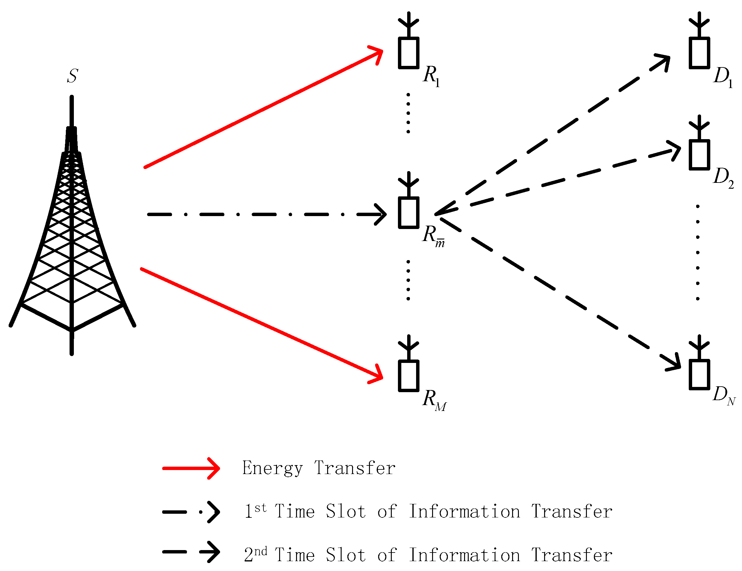
Figure 2.
State transition diagram of the harvested energy amount. (The state denotes the relay has amount of harvested energy at a relay.)
Figure 2.
State transition diagram of the harvested energy amount. (The state denotes the relay has amount of harvested energy at a relay.)

Figure 3.
Outage probability with different (infinite storage of energy).

Figure 4.
Outage probability with different (finite storage of energy, ).
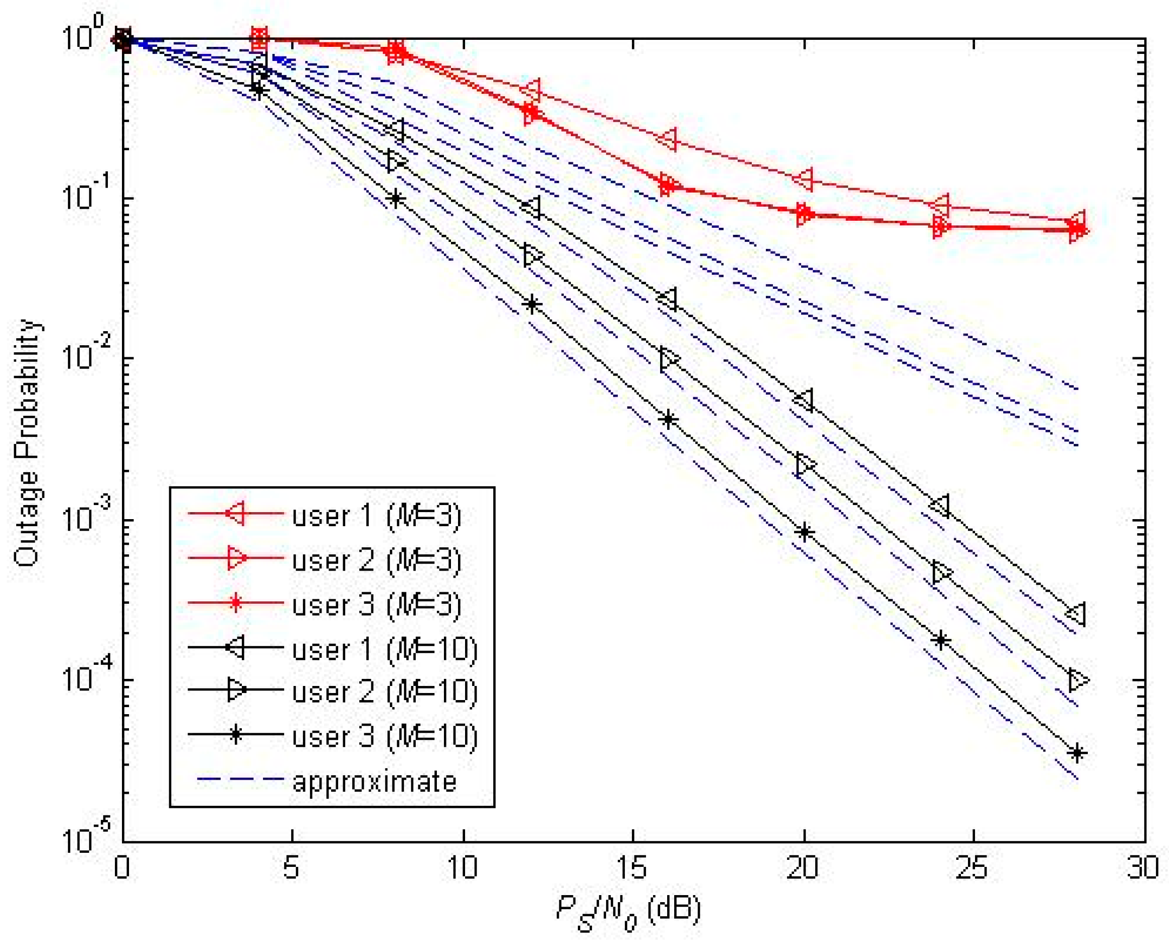
Figure 5.
Outage probability with different (infinite storage of energy).
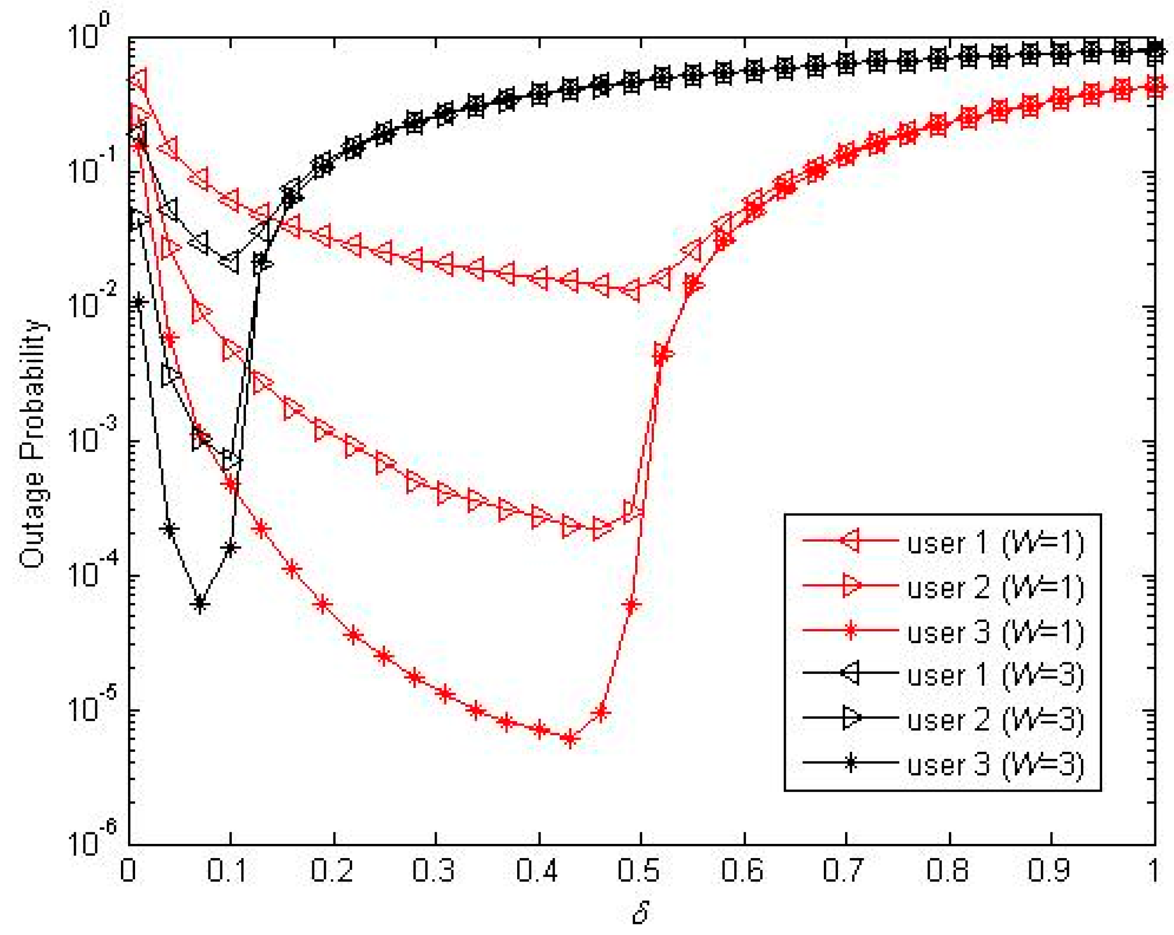
Figure 6.
Outage probability with different (finite storage of energy, ).
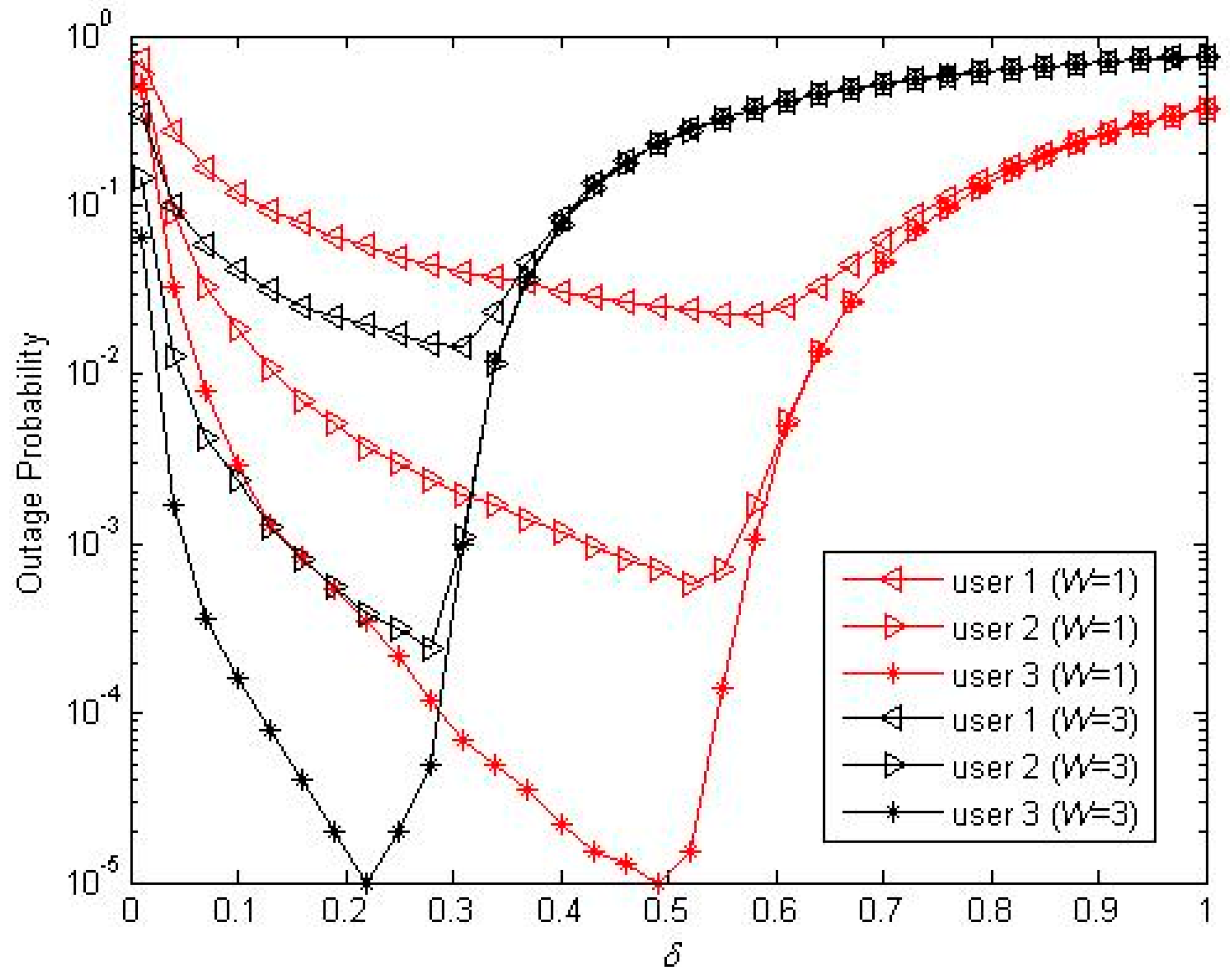
Figure 7.
Outage probability with different ().

Figure 8.
The impact of relay number on the outage probability (infinite storage of energy).

Figure 9.
The impact of relay number on the outage probability (finite storage of energy, ).

© 2017 by the authors. Licensee MDPI, Basel, Switzerland. This article is an open access article distributed under the terms and conditions of the Creative Commons Attribution (CC BY) license (http://creativecommons.org/licenses/by/4.0/).
Share and Cite
MDPI and ACS Style
Guo, W.; Wang, Y. Cooperative Non-Orthogonal Multiple Access with Energy Harvesting. Information 2017, 8, 111. https://doi.org/10.3390/info8030111
AMA Style
Guo W, Wang Y. Cooperative Non-Orthogonal Multiple Access with Energy Harvesting. Information. 2017; 8(3):111. https://doi.org/10.3390/info8030111
Chicago/Turabian StyleGuo, Weidong, and Yunfeng Wang. 2017. "Cooperative Non-Orthogonal Multiple Access with Energy Harvesting" Information 8, no. 3: 111. https://doi.org/10.3390/info8030111
Note that from the first issue of 2016, this journal uses article numbers instead of page numbers. See further details here.