An Architecture to Manage Incoming Traffic of Inter-Domain Routing Using OpenFlow Networks

Center for Informatics, Federal University of Pernambuco, Recife 50740-560, Brazil
Information 2018, 9(4), 92; https://doi.org/10.3390/info9040092
Submission received: 6 February 2018
/
Revised: 9 April 2018
/
Accepted: 11 April 2018
/
Published: 14 April 2018
(This article belongs to the Section Information and Communications Technology)
Abstract
:The Border Gateway Protocol (BGP) is the current state-of-the-art inter-domain routing between Autonomous Systems (ASes). Although BGP has different mechanisms to manage outbound traffic in an AS domain, it lacks an efficient tool for inbound traffic control from transit ASes such as Internet Service Providers (ISPs). For inter-domain routing, the BGP’s destination-based forwarding paradigm limits the granularity of distributing the network traffic among the multiple paths of the current Internet topology. Thus, this work offered a new architecture to manage incoming traffic in the inter-domain using OpenFlow networks. The architecture explored direct inter-domain communication to exchange control information and the functionalities of the OpenFlow protocol. Based on the achieved results of the size of exchanging messages, the proposed architecture is not only scalable, but also capable of performing load balancing for inbound traffic using different strategies.
1. Introduction
The Internet is a collection of tens of thousands of independently operated networks. In the jargon of the Internet, these networks are called Autonomous Systems (ASes). An AS can be an Internet Service Provider (ISP), a campus, a content provider, or any other independently operated network. All these ASes can connect with each other as they execute an inter-domain routing protocol to exchange network reachability information. The Border Gateway Protocol (BGP) [1] is the current standard for inter-domain routing on the Internet and provides reachability information among the ASes.
BGP is one of the most successful protocols on the Internet. However, many researchers have indicated issues related to BGP since its inception, e.g., the lack of end-to-end service guarantees, long convergence time, and security issues [2]. Furthermore, it is well known that BGP suffers from the process of “ossification”, where the architecture becomes very dependent on the protocol, and new features are inherently hard to introduce into the network.
For the BGP, the ossification is due to economic reasons combined with the fact that backward compatibility has to be assured since there is no flag day to switch to a new architecture. Thus, all BGP appliances have to execute the same version of the protocol to operate appropriately, or anomalies in the network may occur (e.g., BGP black holes). Hence, a new feature for the BGP protocol has to have a minimum integration within heterogeneous networks and interoperate through different administrative domains (e.g., the Internet). These requirements have frustrated new proposals to evolve BGP and the ecosystem of inter-domain routing [3].
Although the BGP has some mechanisms to control inbound traffic, for example, Multi-Exit Discriminator (MED), Communities, AS-Path Prepending and others, the effectiveness of applying these mechanisms are unclear and are also not guaranteed once they are indirect approaches. Thereby, BGP inbound traffic control mechanisms try to influence other ASes to change the preference regarding routes, and often the desired traffic distribution cannot be achieved. Furthermore, another difficulty for the manipulation of inter-domain traffic is the BGP’s destination-based forwarding paradigm [1]. This approach limits the granularity of selecting the traffic once the decision of forwarding IP packets only relies on the information of the IP destination header field.
One promising approach to enable network architectures to evolve is Software Defined Networking (SDN). SDN emerged as a new paradigm that allows network engineers to elaborate new network designs and includes desirable features for this evolution such as open programmable interfaces at networking devices, the separation between control and forwarding planes, and innovation occurs in applications executed inside the control planes [4,5,6,7].
A notable SDN technology is the OpenFlow protocol (OF). OF is an open programmable interface for SDN that gained momentum in academia and industry over the last decade [8]. OF is flow-oriented, meaning that the sequence of packets identified by a set of common header fields follows a given path. Thus, OF can provide fine-grain forward capabilities to the network by matching multiple fields of TCP/IP. This work applies SDN concepts and uses the OpenFlow capabilities to compose a new network architecture to evolve inter-domain routing systems.
Here, the proposal is to investigate an architecture to manage inbound traffic in an inter-domain routing system using SDN technologies. The main idea was to depict new mechanisms to be deployed in transit ASes (often an ISP) that can allow a customer AS to execute control tasks for managing how incoming traffic can reach its network. Therefore, the main contributions of this work were:
- Presenting and describing an architecture that uses OF networks and is compatible with current inter-domain routing protocol (BGP);
- Exploring OF features for network traffic engineering tasks in inter-domain routing; and
- Analyzing how the incoming traffic can be managed using the proposed architecture and BGP.
The remainder of the text is organized as follows. Section 2 discusses the related works regarding SDN solutions for inter-domain routing and Section 3 details the proposed architecture. Then, Section 4 describes how the ASes can apply inbound control to manage network traffic towards its networks using SDN applications executed inside the architecture and Section 5 performs an evaluation of the proposal with a proof of concept. Finally, Section 6 provides more discussion on the architecture and Section 7 presents the final thoughts of this work.
2. Related Works
Applying BGP’s inbound traffic engineering techniques (such as Selective advertisement or AS-path Prepending) is a counterproductive approach as these techniques do not guarantee its effectiveness. Moreover, the BGP techniques try to influence the routing decisions of external ASes to obtain their desired inbound traffic distribution, hence network operators that use these approaches are led to a trial-and-error process, where each AS will manipulate its own routing system to fulfill its business goals. Indeed, the problem of inter-domain routing traffic engineering can be seen as a conflicted one where the interactions between ASes can be modeled as game theory and nonlinear programming [9].
The idea of overcoming the BGP’s limitation for control inbound traffic with traditional networks where all the network logic is embedded into network appliances and distributed in the network topology can be classified into: using a type of overlay network [10,11,12], a new network protocol [13,14], or both approaches [15]. All these works shared the drawbacks of requiring executing protocols embedded to network appliances, or an overhead in network management activities to support these solutions. Usually, medium and large networks have a myriad of network appliances and the deployment of solutions with traditional approaches can lead to high CAPEX (capital expenditure) and OPEX (operational expenditure). Nonetheless, SDN has desirable features with the potential to create solutions to evolve the inter-domain routing environment.
Exploring the SDN concepts, the Multi-Dimension Link Vector (MLV) [16] presented a new mechanism to exchange a network view. MLV enabled SDN networks to improve the Internet routing flexibility in an inter-domain network federation by using a link vector algorithm to compose a new way of representing the inter-domain state of the network. With a link vector data structure, the network operator could decide the routes of the inter-domain routing. Even though MLV was a proposal to evolve inter-domain routing among SDN networks, it was not compatible with BGP. This requirement imposed a practical limitation for the wide use of the MLV proposal once SDN networks have not yet been broadly adopted for inter-domain routing.
Regarding integration between the SDN controller and BGP, almost every modern SDN controller has mechanisms to exchange BGP information with others BGP speakers (e.g., legacy routers). For example, the ONF ATRIUM project proposed a framework to support BGPusing ONOS controller [17] and Quagga [18]. Another widely used SDN controller, the Ryu [19], supports interworking between OpenFlow and BGP. Once a BGP component (the BGP speaker) is properly installed in the Ryu SDN framework, the controller can establish BGP sessions with others BGP speakers. Therefore, proposals to cope with an inter-domain environment that is not back-compatible with BGP have little practical appeal. The proposed architecture of this paper is compatible with BGP and provides mechanisms to override the BGP default behavior when it is required.
One proposal that allows BGP rules to be overridden by SDN rules is the Software-Defined Internet exchange (SDX) [20], and its extension, the Industrial-Scale Software Defined Internet Exchange Point (iSDX) [21]. This used the centralized control idea of SDN into an Internet Exchange Point (IXP) and enabled the creation of more flexible forwarding policies, reducing the forwarding table size of OpenFlow devices used by the IXP participants and the end-to-end enforcing of QoS. However, they did not design these proposals to other types of network environments. Here, this paper proposes an architecture to transit ASes, especially the ISPs, to provide management capabilities to other ASes to control their inbound network traffic. Furthermore, the new routing logic occurs directly between the customers and the transit AS that deploys the proposed architecture.
The Route Chaining System (RCS) [22] presented the concept of using SDN networks to allow ASes to select routes that do not follow the standard BGP algorithm and explore the possibility of Internet diversity paths. The RCS explores path diversity in inter-domain routing systems with SDN, focusing on controlling the network traffic in transit ASes from the AS source to their destinations. The RCS also requires an inter-domain communication layer between the ASes to enable this solution. The main drawback of the RCS is the propagation of new types of prefix messages in the inter-domain environment for representing the fine-grain rules. This new inter-domain routing system dramatically increases the signaling, making the solution inviable once it consumes a lot of bandwidth. Here, the idea of this architecture is to mitigate the utilization of the bandwidth to control messages between domains using compression techniques and exchanging the network state by sending it in binary format, and not in plain text.
Furthermore, regarding routing logic, Kotronis et al. [23] proposed SIREN, a solution to offload the routing functions of a customer AS to an external trusted contractor. Thus, this contractor would be responsible for optimizing and managing the network traffic of its customers. The main idea of SIREN is that, with multiple customers, the contractor would eventually get the global inter-domain network state, be able to identify conflicts in inter-domain policies and take actions to optimize customer traffic. The idea of SIREN goes towards the opposite direction of this paper, where it is claimed to give more control to customer ASes that own and advertise its prefixes. Using the architecture of this work, a customer AS can manage the network traffic on the Internet that otherwise, using only the BGP, cannot be achieved. In other words, SIREN pushes more control for ISPs to manage the inter-domain routing of its customer; here, customers have more control of the inter-domain routing once it is the customer’s responsibility to apply the routing logic.
3. The Architecture Proposal
This section is dedicated to presenting the architecture to manage incoming traffic in inter-domain routing using OpenFlow networks. First, an overview of how the architecture can be integrated with legacy networks is provided as well as a pure OpenFlow network infrastructure. Then, the proposed architecture is depicted where each component is described, and the dynamic of how the proposed architecture works is presented.
Afterwards, the proposed architecture is depicted, each component is described, and the dynamic of how the proposed architecture works is presented.
3.1. Network Architecture Overview
A well-established design principle is the end-to-end argument [24]. Based on this principle, the network complexity has to be concentrated in the network edges, making the core simple from the perspective of network management. Thus, the following proposed architecture applies this design principle, and the programmable devices (specifically OpenFlow switches) are positioned at the edges of the network. Hence, two options for the core might occur:
- Legacy network: With the legacy network in the core, the SDN controller is the centralization logic that acts as Route Server for the BGP routers. Figure 1 depicts a scheme for mixing OpenFlow switches and legacy network appliances. The legacy core is connected through internal BGP (iBGP) sessions to the OpenFlow Controller, which distributes external routes to the internal BGP routers. The infrastructure routes continue to be distributed with the interior gateway protocols (such as OSPF) executed in the Legacy core perimeter.
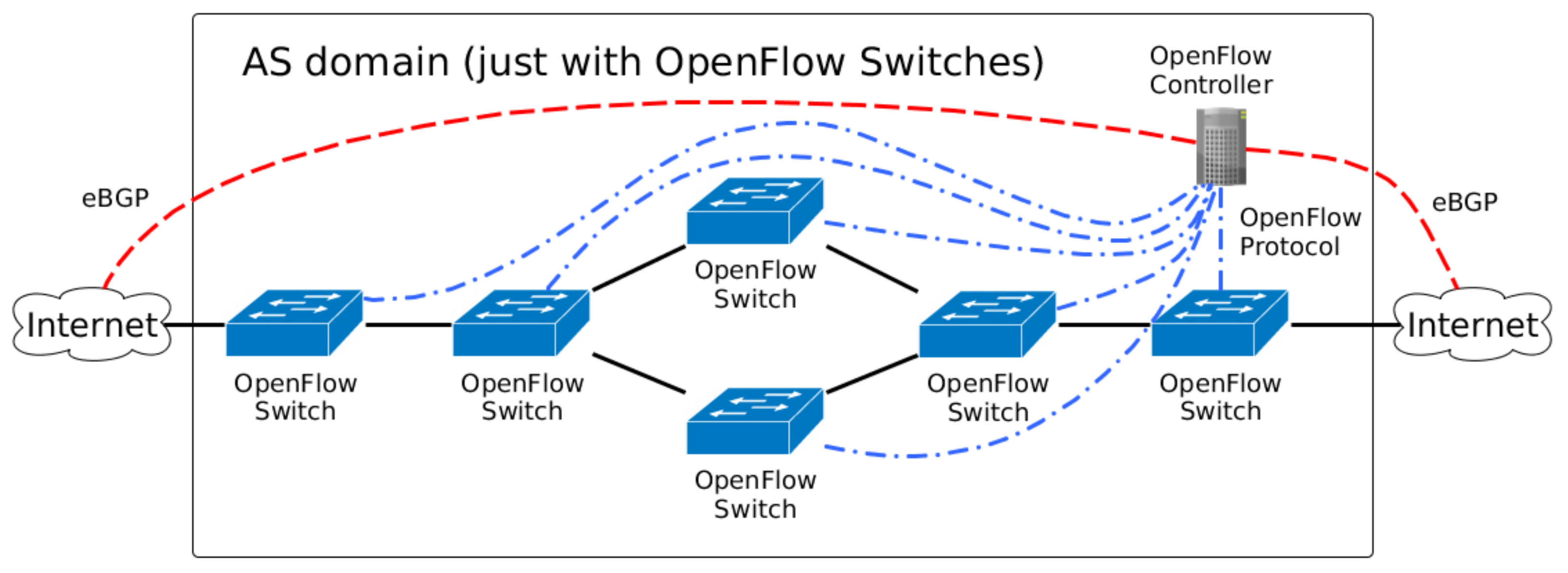
- OpenFlow network: In the future, it is expected that all network devices will have some SDN technology embedded inside an AS. Thus, a domain with SDN technology (OpenFlow devices) is straightforward, and Figure 2 depicts this scenario. All OpenFlow switches are connected to the OpenFlow Controller, which manage the flows inside the AS domain.
3.2. Architecture Components
A more detailed scheme of the proposed architecture is depicted in Figure 3, with the three planes of the SDN architecture. The control plane is the place where the OpenFlow controller is executed, and the four main components are deployed for enabling the proposed architecture: Network Administrator, Policy Manager, East/Westbound and Path Computer.
3.2.1. Network Administrator
The Network Administrator component is responsible for performing the authentication and authorization of connection requests from the Customer AS. It also provides information to the AS app regarding multiple paths and the bandwidth utilization for a given prefix, and verifies the quantity of network traffic destined for the prefixes of the Customer AS. If a change in the RIB_IN occurs (for example, a drawback prefix network), the Network Administrator component notifies the changes to the AS app and informs the Policy Manager and Path Computer components to update the new network state.
To avoid two (or more) AS apps making conflicted decisions about the routing, each AS app is associated with a customer AS, and each customer has their own prefixes registered inside the Routing Registry (RR). Thereby, verifying whether a given prefix belongs to a customer AS is conducted through querying the RR database and, with that information, it is possible to avoid the routing objective of one AS app negatively affecting the routing objective of the other.
3.2.2. Policy Manager
This component is responsible for applying or repealing the policies of the domain that deploys the proposed architecture. It acts with the BGP Speaker and the Path Computer components to implement the domain policies. Thus, if an AS app needs to explore multiple AS-Paths for a given prefix, the Policy Manager will allow, or not, the use of multiple next hops for that prefix. The policies are generated inside the Network Administrator component to be executed in the Policy Manager.
Moreover, the Policy Manager is responsible for avoiding two (or more) AS apps creating rules that go against each other or the AS policies. Then, this component makes routing decisions based on the policies provided from the domain and from the Network Administrator component.
3.2.3. Path Computer
The Path Computer component computes the paths to be installed into the OpenFlow network of the domain that uses the proposed architecture. It sends instructions to the OpenFlow Speaker component to install the OpenFlow rules in the OpenFlow switches. It also receives information about the states of the OpenFlow table that are used to inform the Network Administrator component about the bandwidth utilization of each prefix.
3.2.4. East/Westbound
The East/Westbound component allows communication between the ASes and exchanges control information about the prefixes. Other Network Operators can use this component to perform some control tasks. The communication uses a secure channel (e.g., HTTPS) to send and receive messages in JSON format. The data plane elements (BGP routers and OpenFlow switches) are connected to the BGP Speaker and the OpenFlow Speaker. The first component exchanges NLRI to other ASes through the BGP protocol. Then, the second component enables the programmability of the OpenFlow switches using the OpenFlow protocol.
3.3. Dynamic of the Proposed Architecture
This subsection describes how the dynamics of the proposed architecture. Regarding neighbor peering, the OpenFlow controller has to be informed (all configuration for BGP protocol has to be provided by the network operator in the same way as the traditional BGP configuration) about the port where the BGP Speaker component will establish the peer session for a given neighbor. In addition to the port information, the ASN of the foreign AS and the IP address of the remote router have to be provided. Furthermore, if the IP address of an AS is a multihop, then the number of networks between the BGP Speaker and the router of the neighbor AS has to also be provided as by default, all IP packets from the BGP Speaker to a router neighbor is set with the value 1 in the Time To Live (TTL) IP field for an external BGP connection.
Then, if everything goes as planned, BGP peering is established, and the exchange of NLRI between the peer is complete. The NLRI will compose the RIB_IN, and after applying the Import Policies the LOCAL_RIB is populated. The LOCAL_RIB is generated by executing the BGP decision process. The RIB information is useful to the AS that deploys the proposed architecture as it can provide the other ASes with inbound traffic management for the network traffic that passes through its infrastructure. Thus, the proposed architecture explores the RIB information and provides more management control to customer ASes using inter-AS communication.
Furthermore, if the AS that deploys the proposed architecture allows a customer to manipulate the outbound traffic in its network infrastructure, it will always be limited to the subset of prefixes learned and valid in the LOCAL_RIB. Furthermore, these prefixes have to be in the Routing Registry database and assigned to the same customer that requires inbound traffic manipulation. That is, the remote control of a customer will be limited to only a subset of the local RIB where the destination field must belong to one of the prefixes owned by the customer AS, and a customer AS cannot change the forward network behavior of other prefixes that are not registered to it.
For the exchange control between a customer and a provider of the proposed architecture, it establishes a secure channel between the ASes (e.g., Virtual Private Network (VPN) or Hyper Text Transfer Protocol Secure (HTTPS)), which connects the AS that provides the services (for example, an ISP) to its customers’ ASes. With a security channel, the network operator in the customer AS can exchange management information and monitor the traffic utilization destined to its network infrastructure.
Thus, the AS app of a customer AS will be responsible for manipulating how traffic is managed. The organization of the proposed architecture is aligned with one of the SDN principles, where the logic of the network occurs in applications executed over the controller. The AS app receives the BGP network state (extracted from the RIBs) for the valid prefixes owned by a customer and the network bandwidth usage for each path associated with each prefix. Then, the application can export that information to the customer.
When the network operator in the customer site receives the state of its AS app, it will be able to configure the parameters of the execution of the AS app. This allows the network operator to manage how incoming traffic of the inter-domain network will reach its network infrastructure. For example, the customer AS can send control information that describes how to load balance the traffic that passes through the transit AS as it has access to the available bandwidth usage information for each prefix and the available valid AS-paths.
The default forwarding actions are to use the BGP behavior. With the information on how to treat the traffic, the AS that deploys the proposed architecture can apply the new control for a given network prefix and then override the BGP default behavior when required. Furthermore, both the customer and provided ASes can monitor the network traffic to verify if it has fulfilled the customer’s requirements. Any changes in the BGP global view of the network are rapidly notified to the customer to take the appropriate action.
4. Controlling Inbound Traffic
The control of inbound traffic is executed inside the application plane of the proposed architecture. A customer AS initializes the AS app to manage the network prefixes of the transit AS with the goal of instructing how traffic will be handled. The AS app also receives the network status from the proposed architecture. For example, the bandwidth utilization of each prefix owned by the Customer AS, or the available paths to reach its networks. With that information, the network operation of the Customer AS can send control information to configure how much traffic each path will receive for each prefix in use.
The AS app is responsible for exploring the multiple paths available for a given prefix if it is required. The information about those paths come from the BGP Speaker component that learned all the prefixes advertised by the AS neighbors through external BGP peering. Furthermore, with the information about multiple paths available, the Customer AS can indicate how the traffic will be treated and distributed to those paths.
The BGP protocol uses just one “best” next hop for each prefix even if other paths to those prefixes are valid and available. BGP is not a multipath protocol, and one good reason for that is that exploring multiple paths on the Internet can affect the performance of Transmission Control Protocol (TCP) connections, the most used transport level protocol in the Internet [25].
Thus, distributing packets belonging to a connection through multiple paths can result in poor performance of high-level protocols of the TCP/IP stack [26] (e.g., reordering packets of TCP [27]). In particular, it is often the case on the Internet, which connects heterogeneous types of network appliances and protocols, that the network suffers from different delays among paths. To avoid the problem of exploring path diversity of the Internet, the proposed architecture guarantees that the association of the source and destination of the IP packets will be forwarded through the same path. Then, a 2-tuple composed of the IP source prefix and the IP destination prefix is adopted to define a flow in the OpenFlow network. Therefore, for a given TCP connection, it will use the same path during its time life (if the path is valid and available).
Aligned with the 2-tuple flow definition, there is an also a probe test from the AS app to a customer AS that checks the health of each path in use. Thus, if an inter-domain path suffers a problem (such as a link failure) or a transient loop occurs, the AS app will be notified to not use that problematic path.
Regarding the inbound traffic control, the proposed architecture allows any innovation in the logic behind the AS app for a customer AS. As well explained by Silva [28], there are different strategies for SDN load balancers. However, in this work, it was decided to develop three types of strategies for the load balancers to be used as the control application in the AS app:
- Reactive Random Load Balancer (Random)
- Reactive Round-Robin Load Balancer (RR)
- Reactive Round-Robin Load Balancer with Threshold (RRT)
These three strategies use the reactive flow creation approach [29] where the flows are created on-demand in the response of a packet that requires a new flow. The baseline for the comparative will be the default behavior of the BGP that uses the “best” next hop to the forward packets. The remainder of this section is dedicated to depicting each approach.
4.1. Reactive Random Load Balancer (Random)
A reactive load balancer creates flows on-demand. Consequently, when there is no OpenFlow rule installed in the data plane’s devices that match against the incoming packet, the controller is notified. Thus, the work of a reactive load balancer with random selects a path from a list of valid and available paths by submitting that list to a Random algorithm. Then, it randomly selects one of those paths to compose a new rule for that flow. Algorithm 1 depicts the Reactive Random Load Balancer (Random).
| Algorithm 1 Reactive Random Load Balancer |
|
4.2. Reactive Round-Robin Load Balancer (RR)
Instead of a Random algorithm, a reactive load balancer with Round-Robin applies the Round-Robin algorithm to the list of available and valid paths. The Round-Robin scheduling algorithm is the simplest and easiest to be deployed once the first element in the list is selected and added in the tail of that list. This process is continuously repeated following the list in a circular order and selects each path in the list equally. Algorithm 2 presents the Reactive Round-Robin Load Balancer (RR) scheme.
| Algorithm 2 Reactive Round-Robin Load Balancer |
|
4.3. Reactive Round-Robin Load Balancer with Threshold (RRT)
The reactive load balancer with Round-Robin and threshold is an extension of the aforementioned strategy where a threshold of bandwidth usage is provided for each path in the list. Thus, if the bandwidth of a path overcomes this threshold, the algorithm must consider the associate path congested and not able to be used for flow creation until the usage becomes lower than the threshold value. Algorithm 3 depicts the RRT algorithm.
To be clear, all the already created flows assigned to the path that has overcome the threshold will continue to use that path, even when the path state is congested. This decision will avoid degradation in the transport level protocols that require keeping the state of established connections.
| Algorithm 3 Reactive Round-Robin Load Balancer with Threshold |
|
5. Proof of Concept
The goal of this evaluation is the execution of the proposed architecture to control inbound traffic by exploring the available outbound links of a given ISP to a prefix destination. First, however, a common topology is extracted from the Internet topology information, and afterwards, a prototype network based on that topology is depicted. Then, the definition of workloads to be used in the prototype is followed by two scenarios. The first explores the management of inbound traffic using different strategies, and the other scenario investigates the prototype when an external link fails and the OpenFlow technologies take place.
This section finishes with a study of the signaling overhead of the proposed architecture seeking to investigate the architecture’ scalability. This was done by using a worst case for the size of East/Westbound messages, and the evaluation of how it impacted the utilization of bandwidth for an AS.
5.1. Topology Adopted
To adopt a topology for composing the evaluation scenario, the CAIDA’s AS relationship database [30] was used for the characterization of multi-homed ASes. It was expected that those ASes get more advantages of the proposed architecture as they can allow them to control and explore the path diversity of the Internet.
The period from December 2015 to October 2017 was considered. Figure 4 presents the total number of public ASN in CAIDA’s AS relationship database as well as the total number of stub ASes with public ASN and a subset of this total representing the total number of multi-homed stub ASes with two relationships of customer-to-provider. Thus, as the multi-homed customer ASes with two ISPs are typical in recent months of the Internet, and, considering the hardware resources of this research, the evaluation testbed of the proposed architecture adopted a topology with two outbound links, one for each ISP, and a multi-homed customer AS.
Based on the data above extracted from CAIDA’s relationship database, the topology adopted its depiction in the Figure 5. It consisted of four ASes, where three of them were transit ASes (AS 100, AS 300, and AS 200), and a stub AS (AS 400). The relationship of customer-to-provider was: AS 400 to AS 300, AS 400 to AS 200, AS 300 to AS 100, and AS 200 to AS 100. As AS 100 deployed the proposed architecture, a new relationship of customer-to-provider was created between AS 100 and AS 400, with the goal of managing inbound traffic to the customer (in this case, AS 400).
The RIB of the AS 100 for the customer AS 400 was indicated in Figure 5, where AS 400 advertised the network prefix 172.16.0.0/24 and the AS 100 learned this prefix propagated through eBGP sessions between all the ASes in the topology. The AS 100 learned that it could reach network 172.16.0.0/24 either through the AS-path [200,400] or through the AS-path [300,400].
The default behavior of the proposed architecture followed the outcome of the BGP decision process where the preferable next hop to reach the Server of AS 400 was by using the path of AS 200. This preferable path is indicated in Figure 5 with the character “>”, and the character “*” indicates that both routes were valid as the result of the BGP decision process. The length of the AS-Path was equal for both paths to the network 172.16.0.0/24. The BGP decision process selected the path [200,400] to be the next hop for that prefix; however, as the Network Operator in AS 400 could use the proposed architecture executed in AS 100, it could explore the use of both paths, if the AS 100 allowed it.
Once there was a relationship between AS 400 (Customer) and AS 100 (Provider) using the proposed architecture, the AS 100 could offload the control of traffic that went to the network prefixes of AS 400. In the topology adopted, only one prefix was available for the customer AS 400 to manipulate it, and two options of paths to reach that prefix. When the AS app of AS 400 did not apply the load balancing, it followed the standard BGP behavior and forwarded all network traffic to just one “best” next hop (per prefix).
5.2. Prototype Environment
To set up the prototype environment, two physical machines were required to implement the topology adopted (see Figure 5). One physical machine executed the following components of the prototype environment: the OpenFlow Switch, the SDN Controller of AS 100, and the 50 Networks. Each 50 Networks propagated its prefix and had only one virtual machine to generate traffic. For convenience, those prefixes ranged from 192.168.1.0/24 to 192.168.50.0/24. Furthermore, the configuration of the physical machine was an 8 CPU core with a maximum clock rate of 2.20 GHz, 8 GB of RAM, and a network card of 1 Gbps. For the AS 100 configuration, each virtual machine in the 50 Networks was emulated using a container (lightweight virtualization). For the OpenFlow Switch, the Open vSwitch [31] was used. The protocol enabled in the Open vSwitch was OpenFlow version 1.3. The proposed architecture was executed in the modules of the Ryu SDN controller [19].
The other machine had a 3 GB of RAM, CPU with a maximum clock rate of 2.4 GHz, and a network card of 1 Gbps. This machine was used to create AS 300, AS 200, and AS 400. Those ASes were an instance of the full virtual machines executed in Virtualbox [32] with Quagga [18]. The terminal of the virtual machine of AS 400 was used to send and receive JSON messages between the OpenFlow Controller in the AS 100 and the AS 400.
A crossover Ethernet cable was used to connect the physical machines. However, to avoid interference between the OpenFlow Switch and the AS 300 and AS 200, it divided the 1 Gbps bandwidth between the two machines with the Linux tc tool (traffic control), allocating two virtual interfaces of 100 Mbps. Thus, the connection between AS 300 and the OpenFlow Switch had an available 100 Mbps as well as the connection between AS 200 and the OpenFlow Switch. Hence, the network traffic from AS 100 to AS 400 is limited to the 100 Mbps passing through path AS 200 and AS 400, as well as the path AS 300 and AS 400.
Regarding the network traffic, the perform network throughput tests tool iperf [33] was used. Each of the virtual machines in 50 Networks used the iperf to generate UDP packets in a controllable way. Furthermore, for the Server component, it was executed in the iperf [33] in UDP server mode, which was started in the AS 400 network. The server was set up with the IP address of 172.16.0.1/24, and connected to the BGP router in the AS 400 infrastructure.
5.3. Workloads
To test how the management of inbound traffic could be performed using the proposed architecture, several workloads schemes were designed to investigate the bandwidth usage in the prototype environment when applying the three types of strategies presented in Section 4. The workloads were:
- Maximum constant network traffic for BGP behavior: This workload produces 100 Mbps of bandwidth usage during the 50 Networks 30 s of use iperf in client mode to generate the UDP packets. The workload was designed to explore the BGP behavior of using just one “best” next hop (per prefix). Thus, based on the adopted topology in Figure 5, this workload will only use one path to carry this traffic, either path [200,400] or path [300,400], but not both to reach prefix 172.16.0.0/24 of AS 400.
- Constant network traffic with balanced rate: Different from the Maximum constant network traffic for BGP behavior, this workload produces 200 Mbps of bandwidth from the 50 Networks. The total volume of traffic is split equally into each network. Hence, each one will be responsible for producing 4 Mbps of network traffic using UDP packets during the 30 s.
- Constant network traffic with unbalanced rate: Similar to constant network traffic with a balanced rate workload, however, with network traffic it will be configured to become unbalanced. Thus, the 50 Networks is split in half, and 25 of the 50 Networks will generate 7 Mbps and the other 25 will generate 1 Mbps of network traffic using UDP packets for 30 s, where the total number of bandwidth produced is 200 Mbps in this interval.
5.4. Scenario I—Manage Incoming Traffic Using Different Strategies
This scenario investigated how the different strategies could play a role in managing incoming traffic. It used the topology adopted (see Figure 5), and explored the strategies for controlling inbound traffic explained in Section 4.
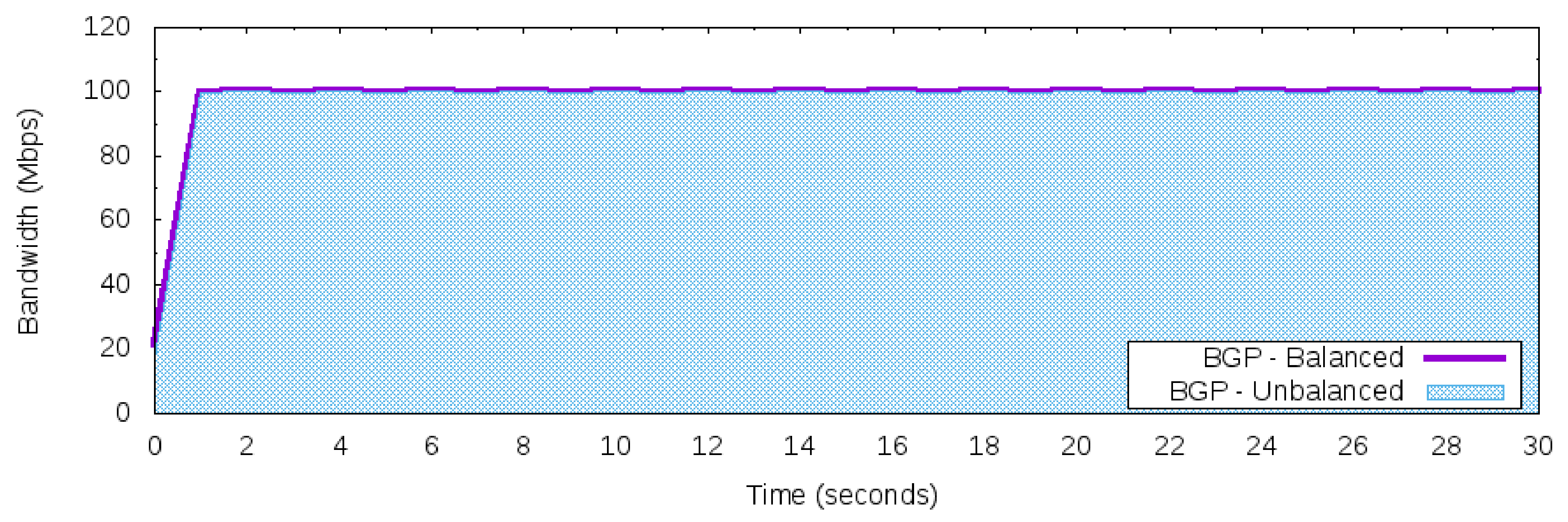
Figure 6 presents the execution of Workloads 2 and 3 using the standard BGP behavior. Due to the BGP’s destination-based forwarding paradigm, all 200 Mbps of the network traffic generated from the 50 Networks to the Server is strangled into one of the “best” next hops. Hence, the selected next hop to the Server is the path [200,400], and then the network traffic was forwarded to AS 200. Once the maximum available bandwidth to this path is 100 Mbps, the results in Figure 6 reflect that limitation. Hence, even if the workload is balanced or unbalanced, the maximum bandwidth reaching the Server is 100 Mbps. For convenience, the unbalanced workload will be used as a reference for analyzing the results for the other control applications.
The results of the reactive Random load balancer control application (see Section 4.1) to Workloads 2 and 3 is depicted in Figure 7. Practically, both workloads were distributed equally to the valid and available paths [200,400] and [300,400]. Compared against the reference of BGP behavior (uses just one “best” path per prefix), the Random optimized and used all of the 200 Mbps available bandwidth to reach the Server. This doubled the utilization of the inbound links of AS 400 for both workloads (balanced or unbalanced) when compared against the BGP reference.
Considering the Round-Robin load balancer (RR), Figure 8 presents the results. The RR reached the full bandwidth utilization only for the workload that generated the balanced network traffic. The unbalanced traffic was not well distributed and did not explore the full potential of the available and valid paths of the topology. The unbalanced workload produced a more similar result to the BGP behavior (BGP–unbalanced workload) than when the balanced workload was used.
The Round-Robin load balancer with the threshold (RRT) was also used. The threshold selected was 95% of the bandwidth for each available path. If this threshold was crossed, then the inbound control application used just the “best” next hop selected from the BGP. The results are shown in Figure 9. As expected, with the balanced workload, the RRT reached the full bandwidth utilization for the prefix 172.16.0.0/24 of the AS 400. These results corroborated with that found for the RR control application. However, for the unbalanced workload, the RRT was close to the 200 Mbps of bandwidth, and was a better result than RR.
5.5. Scenario II—External Link Failure
This scenario captured the dynamic of a disruption of an external link when the domain that deployed the proposed architecture was protected with the FF rules of OpenFlow. The main goal of this scenario was to mitigate the unavailable time of the domain during the disruption of an external link, taking into account the FF mechanism and exploring the multiple paths allowed by the proposed architecture.
This scenario used Workload 1 and the prototype environment describing the adopted topology (see Figure 5). To avoid any delay or packet loss that could be caused during the OpenFlow rules installation process, all FF rules were installed before the execution of the workload. An example of the state of the table rules is depicted in Table 1.
Suppose that OpenFlow Switch of Figure 5 is the edge device of AS 100. As the workload was designed to explore the BGP’s destination-based forwarding paradigm, the best next hop for the prefix 172.16.0.0/24 is through the AS 200. If the domain AS 400 can apply inbound control over the prefix 172.16.0.0/24 in the AS 100, then all traffic from the 50 Networks can be forwarded as the AS 400 wishes.
The first 50 lines of the OpenFlow Switch flow table reflected this scenario, and used the group table Group1 identifier, where it forwarded packets to AS 200 when the external link to this AS was live (not failed), or otherwise to AS 300. The last OpenFlow rule is the routing safety rule, where all the remaining traffic that does not match against previous rules will be forwarded. The Group2 identifier was used to forward network traffic for path [200,400], which was the “best” next hop for the BGP AS 400’s prefix.
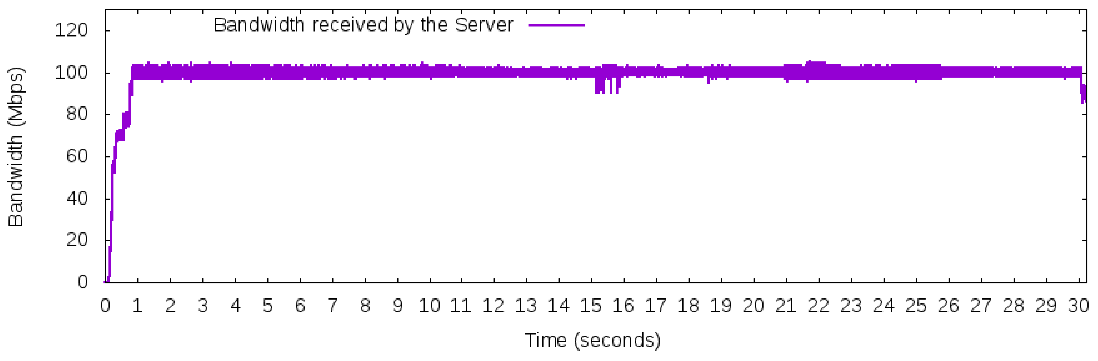
Regarding the experiments, Figure 10 depicts the average bandwidth received by the Server during the execution of Workload 1. The workload was executed more than 30 times with a confidence interval of 95%. As the disruption of the link was not perfectly synchronized with the start of the capture (in milliseconds time), the computation of the average bandwidth produced a graph that did not present a discontinued interval around the 15th second. However, Figure 10 indicates that the FF mechanism did not affect the total bandwidth available to the workload once the maximum available bandwidth was used practically during the entire 30 s interval.
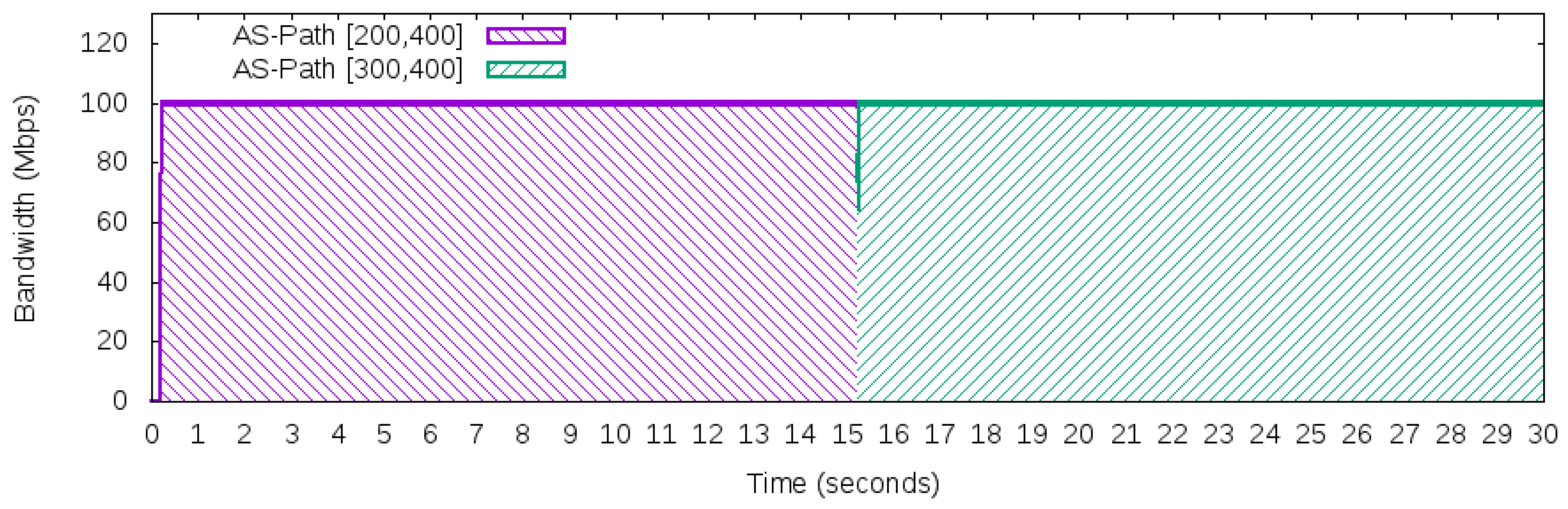
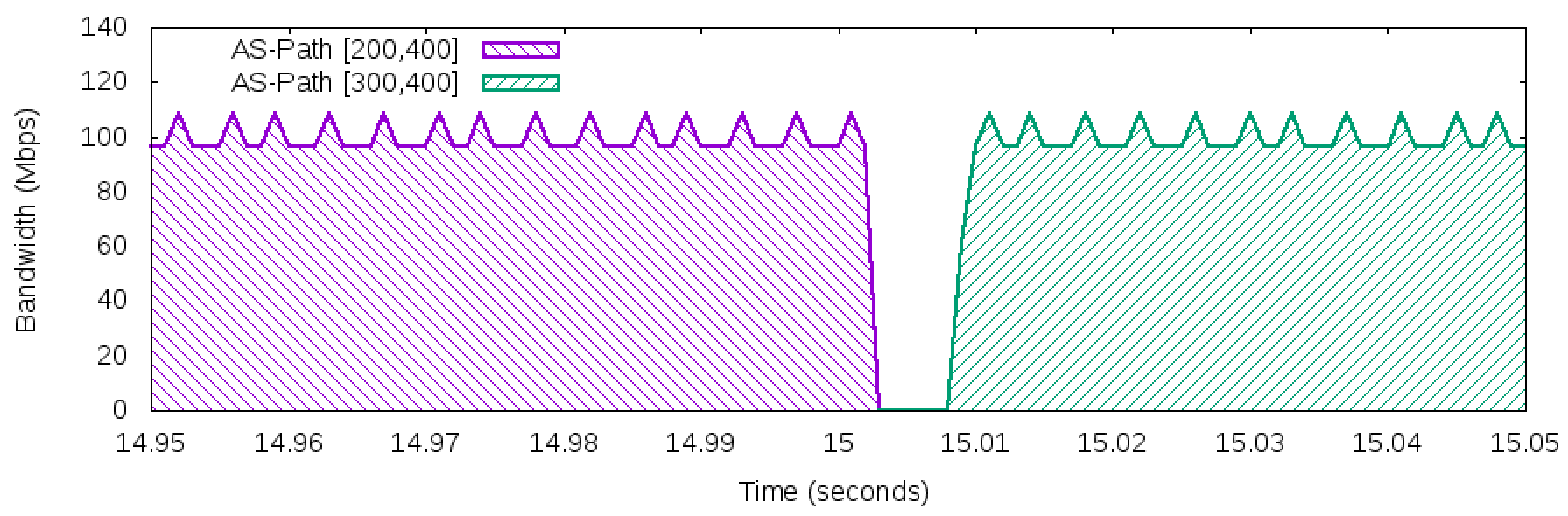
In fact, a sample of the execution of the selected workload is presented in Figure 11, which shows how the traffic used different paths to reach the Server. Although Figure 11 describes the network behavior of the traffic generated during the 30 s, it does not provide details about the disruption event that occurred in the 15th second. Next, Figure 12 details what happened in between the times of 14.95 s and 15.05 s of this scenario.
The workload produced 100 Mbps of network traffic and used the path [200,400] as the “best” next hop and path [300,400] as a backup path. In the 15th second, the link connecting AS 100 and AS 200 failed. After the link failure in the 15th second, the FF mechanisms took a few milliseconds to discover the disruption. Once this occurred, the traffic automatically shifted from path [200,400] to path [300,400]. This process was done exclusively in the data plane (OpenFlow switches) and took less than ten milliseconds, which is an acceptable value for disruption in an inter-domain environment (less than 50 ms [34]). The measured millisecond interval was coherent with the FF mechanism recovery times found in the literature [35,36].
The main result of this scenario was that, by exploring the valid and available multiple paths of BGP, the proposed architecture avoided the application of the BGP decision process for selecting a new best next hop when an external link failed. The BGP convergence is a time consuming process (dozens or hundreds of seconds [37,38]) when deciding a new route, and with the application of the proposed architecture mechanisms, if it exists, a valid next hop will then always be already computed and installed in the data plane, and then the domain can immediately use the spare route. Therefore, the proposed architecture can bring the unavailability of paths to the milliseconds time after an external link failure, instead of being subject to the long BGP convergence time.
5.6. Signaling Overhead
The evaluation metrics for the SDN protocols were highlighted by the survey of Mendiola et al. [4] who indicated that the number of messages and the size of the messages were criteria for the measurement scalability of the SDN solutions. Based on this claim, the signaling overhead was measured of the proposed architecture for the size of East/Westbound messages.
The dataset of CAIDA contained IPv4/IPv6 Prefix-to-Autonomous System (AS) mappings [39]. With that dataset, it was possible to verify the size of the messages required to update the network state of a customer. Thus, from the CAIDA database, the AS that owned the most number of prefixes on the Internet (in 2017) was extracted, which was value of 5416 prefixes. This value was the worst case possible as no other AS would require a bigger network state message. Furthermore, with that quantity of prefixes (worst case message), a JSON message was generated using the East/Westbound component, and the size of this message was measured.
The bandwidth required to transmit the size of the message in the worst-case scenario, and various intervals of time were used with the goal of diluting the size of the message through those intervals, hence decreasing the bandwidth needed. The results are presented in Table 2, where the various intervals of time were adopted, and the bandwidth required for transporting the worst-case message.
This was applied through ZIP compression to reduce the bandwidth required for the worst-case message (see Table 2). Therefore, the quantity of bandwidth required to transmit the biggest network update was relatively small when considering peer-to-peer communication, especially if some compression was applied. Furthermore, gaining better control of the utilization of available bandwidth for inbound traffic had the potential to overcome the waste of bandwidth in the use of signaling messages between a domain that deployed the proposed architecture and its customers.
6. Further Discussion
The Internet is intrinsically heterogeneous and distributed where network operators execute independent network management tasks into their AS domain [40]. Additionally, the lack of direct BGP mechanisms to control inbound network traffic contributes to the over-provisioning of ASes infrastructure, leading to an inter-domain environment consisting of expensive, high-performance, and specialized hardware. Consequently, these network resources are underutilized by around 30% to 60% [41] to cope with disruption or unpredictable changes of connectivity in the inter-domain environment.
Moreover, the BGP does not provide an effective mechanism to control inbound traffic for prefixes advertised to other ASes. All traffic engineering tools available with BGP only rely on techniques that try to influence other BGP speakers to generate the network traffic distribution desired. Thus, this work explored the possibility of adopting SDN technologies in the inter-domain environment (for example, an ISP) and providing new routing network services to customers of the transit ASes that deploy the proposed architecture.
A prototype was used to execute an experiment of how to perform load balancing for inbound traffic to a given AS. Although the scenario adopted consisted of few ASes, a common configuration in current Internet topology was extracted, which was expected to be represented in a real scenario deployment. Furthermore, based on the achieved results, the proposed architecture was effective for allowing customers of a transit AS to control the inbound traffic.
6.1. Number of Network Rules
It is evident that exploring multiple paths of customers prefixes can increase the demand for OpenFlow rules. For example, in the topology adopted (see Figure 5), the execution of a load balancer application increased times the number of OpenFlow rules required to forward a given customer prefix, where n is the number of source network prefixes needed to be managed by the transit AS. Thus, instead of just one forward rule to the prefix 172.16.0.0/24 to the AS 400 (the default “best” next hop of BGP rule), 51 OpenFlow rules were required to manage the inbound traffic for the customer AS from the 50 prefixes of the 50 Networks.
Regarding the number of network rules, the OpenFlow protocol required multiple match fields to compose a single rule, and the OpenFlow switches often deployed a flow rule using the Ternary Content Addressable Memory (TCAM). TCAM memories are a high-speed memory, but with the limitation of very high monetary costs. Moreover, TCAM requires a lot of space in its chip hardware and has a notoriously high energy consumption. Thereby, due to the fine-grain of the OpenFlow rules, these rules can be cumbersome to an inter-domain environment where the number of prefixes (or flows) is tremendously high [42]. Thus, it is worth noting that any OpenFlow based solution requires appropriate flow management. The rule placement problem inside an OpenFlow network is further detailed in the excellent and extensive survey of Nguyen et al. [43].
Furthermore, OpenFlow specification, and hence the OpenFlow switches, aims to make the data plane elements flexible and efficient as Application Specific Circuits Integration (ASCI) used in the BGP routers (traditional network approach). However, to increase the flexibility of the OpenFlow protocol, the number of TCP/IP protocols supported for each new version of the OpenFlow protocol stumbles into the TCAM limitations. Therefore, a trade-off between flexibility (e.g., number of match fields) and performance (for example, number of rules) must be reached. Ideas for allowing OpenFlow data plane elements to be more flexible and programmable are at the very beginning such as P4 [44] or OpenState [45] and can be an answer for the flexibility and performance of OpenFlow switches.
6.2. Adopting a Routing Registry
One major concern in BGP inter-domain routing is the exploration and impersonation of the ownership of IP prefixes for ASes. Hijacking, misconfiguration, and errors [46] can lead to the disconnection of portions of the Internet (black hole routing), Man-In-The-Middle attacks (MITM), Distributed Denial of Service (DDoS), and other security issues. These issues occur because the control plane of BGP does not provide security mechanisms for discovering what an AS owns and is allowed to advertise for a given prefix.
To be reachable on the Internet, an AS has to inform the prefixes its network is configured and passes those values to its ISP (or its Peers). Often, this is done basically by signed contracts between ASes during the establishment of their AS relationships, and an agreement of which Routing Registry (RR) is used. An Internet Routing Registry (IRR) is a database on ASNs and IP routing prefixes. A registry in an IRR is used for configuring BGP routers to avoid security issues between ASes [47].
When a RR is adopted, it is possible to build filters based on the registries of that database. Although there are some global IRRs (for example, ARIN’s IRR [47]), often the providers run their Routing Registries. The problem of using a global Internet Routing Registry is that the current efforts do not provide extensive, updated, and reliable databases of most of the ASes, and hence the registries usually do not reflect the reality of the ASes relationships and the ownership of their prefixes.
6.3. East/Westbound Discussion
Regarding the East/Westbound SDN interfaces, SDN technologies (such as OF) can centralize the control of the network and require network functions such as monitoring capabilities or import and export data to exchange control information between the different controllers. As recent surveys have indicated, there is no standard to exchange network control information between different SDN controllers [40,48], although some initiatives have tried to standardize an East/Westbound for SDN controllers, for example, ALTO [4,49].
To communicate among the SDN controllers in the inter-domain ecosystem, the authors in [40] proposed an interface for the SDN to exchange reachability and topology information. The goals were to present a peer-to-peer mechanism to exchange network information and be resilient and secure for ASes. As highlighted by [6], the SDN does not have a universal interface (East/Westbound API) for the integration of heterogeneous SDN controllers as it is easy to develop (it is just software, no hardware development involved). This interface is also dependent on niche markets where a given SDN controller has to satisfy the business requirements where it has to be deployed.
The proposed architecture uses its East/Westbound interface to allow a more in-depth integration with the business systems of its customers. It is different from other approaches that only integrate legacy routers with SDN technology. For example, RouteFlow [50] uses Quagga as the main engine to control and configure flows of OpenFlow switches via a proxy for the OpenFlow controller, and all the network logic follows traditional network protocols, which in the case of inter-domain routing is the BGP protocol. Here, it is possible to refine the control task of managing inbound network traffic, when a customer is allowed to do so, by overriding the BGP behavior and exploring multiple available and valid paths in the inter-domain environment.
This work is a step forward in the understanding of adopting an East/Westbound interface between different domains, especially in the inter-domain environment. Furthermore, regarding classification, the solution of using an East/Westbound interface for the proposed architecture makes it classified as a Peer-to-Peer application (P2P) based on the work of Nobre et al. [51].
6.4. The Proposed Architecture in the Internet
To investigate the potential of the proposed architecture on the Internet, the CAIDA’s database [52] was used to rank the ASes that provide transit to other ASes. The ranking was based on the Customer Cone metric, which measures the number of direct and indirect customers of a given AS. The data for ranking the ASes was based on the Customer Cone metric and was extracted from the topological data collected by CAIDA and BGP routing in June 2016. A total of 54,772 ASes comprised the dataset used.
Thus, the first ten ASes in this ranking were selected and the number of ASes in their Customer Cone were measured. Figure 13 depicts the potential of the proposed architecture in the Internet. The first 10 ASes in the ranking had an expressive quantity of direct or indirect customer relationships that could allow those customers to use the benefits of the deployment of the proposed architecture. Therefore, if one of those 10 ASes provided network services to control the inbound management of network traffic to its customer in the cone, those customer ASes could explore the path diversity of the Internet by using an AS app, as shown in the previous section.
Furthermore, the proposed architecture acted in the BGP decision process and allows an AS that deployed this technology to offload its control for customer ASes. Next, a customer could manage inbound traffic by applying control mechanisms for network traffic toward its prefixes. The premise was that stub ASes would be willing to have that control and eventually could establish new relationships to transit ASes on the Internet.
This type of relationship, where any AS can create a relationship with any other AS, is very difficult in the current Internet architecture. The benefits for the customers’ ASes is the appropriate management of their inbound network traffic and for the transit ASes to provide new network value-added services. Obviously, the offload of control from the transit AS would hardly be available for free and will probably provide those new network services if and only if it had some political or financial incentives. Thereby, a transit AS that executes the proposed architecture could explore the new routing services economically and hence increase its profit that would be reachable via collaboration among ASes or due payment. Therefore, a new economy plane for the Internet [53] could emerge and the financial appeal of the proposed architecture is the incentive to transform and evolve the inter-domain environment [3].
Besides having more control of the inbound network traffic, increasing control in the inter-domain routing could also be beneficial for the security of the Internet. For example, it is well known that the mitigation of Distributed Denial of Service (DDoS) is more effective when applying defense mechanisms as close as possible to the source of the attack [54]. As the detection is more precise in the AS suffering a DDoS attack, it can respond by expanding its defense mechanism through other ASes. This will have the potential to inhibit the occurrence of DDoS once the defense mechanism can be expanded to being as close as possible to the source of the attack. Future works will focus on mitigating DDoS flooding attacks with the proposed architecture.
6.5. Future Works and Limitations
All the network logic in the SDN architecture resides inside applications executed over SDN controllers. The three strategies for load balancers used in this work followed the reactive flow creation. Hence, for future works, it is interesting to investigate the different approaches for the manipulation of flows in an OpenFlow network, for example, proactive and active strategies [29]. Another idea in this line of thought is to manage and apply a more aware congestion control for the flows, e.g., a switchover mechanism [36] that changes congested flows to different paths during the lifetime of the flows.
For future works, the execution of different protocols to compose the workload has been considered. One limitation of this work is that it only used UDP flows. The exclusivity of this protocol in the experiments was justified for the sake of space and time, and the metric adopted in this work, the bandwidth of the paths. However, the use of the iperf tool to set up and generate TCP flows will be the next step.
TCP flows will be designed to be as representative as possible to typical Internet TCP flows. The importance of this investigation will discover the sensitivity of the throughput of TCP flows to dropped packets as realistic Internet traffic tends to be highly dynamic, with individual flows varying in their bandwidth utilization. Thus, with more realistic traffic, it will be possible to analyze whether there is any improvement in the throughput, as was seen in the described experiments using UDP flows.
Another idea to be explored is the creation of a numerical network model to be executed over BGP topology. A good question to be answered will be how much path diversity on the Internet can be improved with a large adoption of the proposed architecture. Exchange Internet Points (IXPs) and Content Distributed Networks (CDNs) can contribute to increasing the capillarity of the Internet traffic, which is reflected in the BGP topology. The proposed architecture can make it interesting for transit ASes to provide a new type of network services to stub ASes, principally for the management inbound network traffic.
7. Conclusions
The BGP protocol does not provide an effective mechanism to control inbound traffic of advertised network prefixes. This work tackled this gap in the literature and proposed a new architecture to manage incoming traffic to multi-homed ASes where their ISPs, using OF networks, provide new services to allow customer ASes to apply network management tasks into the ISPs infrastructure. This work proposed and executed experiments on how the proposed architecture could be used to provide more network traffic control using the capabilities of OpenFlow networks. The results indicated that the effective of the inbound control mechanisms to manage incoming traffic for the inter-domain routing was dependent on the logic executed in applications of the proposed architecture.
Furthermore, the proposed architecture was extensively discussed including the limitation of the OpenFlow technology, previous works, the mechanisms to exchange control information among SDN domains, the attractiveness of deploying the architecture in the current Internet, and future works. In conclusion, the results and the extensive discussion of the proposed architecture makes this work a step further in the literature of the mechanisms for managing Internet traffic.
Conflicts of Interest
The author declare no conflict of interest.
References
- Rekhter, Y.; Li, T.; Hares, S. A Border Gateway Protocol 4 (BGP-4), Network Working Group. 2006. Available online: https://www.rfc-editor.org/rfc/pdfrfc/rfc4271.txt.pdf (accessed on 10 April 2018).
- O’Donnell, R. A Survey of BGP Security Issues and Solutions. Proc. IEEE 2010, 98, 100–122. [Google Scholar] [CrossRef]
- Silva, W.J.A.; Sadok, D.F.H. Control Inbound Traffic: Evolving the Control Plane Routing System with Software Defined Networking. In Proceedings of the 18th International Conference on High Performance Switching and Routing (HPSR), Campinas, Brazil, 18–21 June 2017. [Google Scholar]
- Mendiola, A.; Astorga, J.; Jacob, E.; Higuero, M. A Survey on the Contributions of Software-Defined Networking to Traffic Engineering. IEEE Commun. Surv. Tutor. 2017, 19, 918–953. [Google Scholar] [CrossRef]
- Nunes, B.A.A.; Mendonca, M.; Nguyen, X.N.; Obraczka, K.; Turletti, T. A survey of software-defined networking: Past, present, and future of programmable networks. IEEE Commun. Surv. Tutor. 2014, 16, 1617–1634. [Google Scholar] [CrossRef]
- Kreutz, D.; Ramos, F.M.V.; Veríssimo, P.E.; Rothenberg, C.E.; Azodolmolky, S.; Uhlig, S. Software-Defined Networking : A Comprehensive Survey. Proc. IEEE 2015, 103, 14–76. [Google Scholar] [CrossRef]
- Silva, W.J.A. Avoiding Inconsistency in OpenFlow Stateful Applications Caused by Multiple Flow Requests. In Proceedings of the International Conference on Computing, Networking and Communications (ICNC), Maui, HI, USA, 5–8 March 2018; pp. 543–548. [Google Scholar]
- McKeown, N.; Anderson, T.; Balakrishnan, H.; Parulkar, G.; Peterson, L.; Rexford, J.; Shenker, S.; Turner, J. OpenFlow: Enabling Innovation in Campus Networks. ACM SIGCOMM Comput. Commun. Rev. 2008, 38, 69–74. [Google Scholar] [CrossRef]
- Wang, N.; Ho, K.H.; Pavlou, G.; Howarth, M. An overview of routing optimization for internet traffic engineering. IEEE Commun. Surv. Tutor. 2008, 10, 36–56. [Google Scholar] [CrossRef] [Green Version]
- Lee, S.J.; Banerjee, S.; Sharma, P.; Yalagandula, P.; Basu, S. Bandwidth-aware routing in overlay networks. In Proceedings of the IEEE INFOCOM, Phoenix, AZ, USA, 13–18 April 2008; pp. 2405–2413. [Google Scholar]
- Quoitin, B.; Bonaventure, O. A cooperative approach to interdomain traffic engineering. In Proceedings of the NGI 2005- Next, Generation Internet Networks: Traffic Engineering, Rome, Italy, 18–20 April 2005; Volume 2005, pp. 450–457. [Google Scholar]
- Yang, X.; Clark, D.; Berger, A.W. NIRA: A new inter-domain routing architecture. IEEE/ACM Trans. Netw. 2007, 15, 775–788. [Google Scholar] [CrossRef]
- Herrmann, D.; Turba, M.; Kuijper, A.; Schweizer, I. Inbound Interdomain Traffic Engineering with LISP. In Proceedings of the IEEE 39th Conference on Local Computer Networks (LCN), Edmonton, AB, Canada, 8–11 September 2014; pp. 458–461. [Google Scholar]
- Qin, D.; Yang, J.; Liu, Z.; Wang, H.; Zhang, B.; Zhang, W. AMIR: Another multipath interdomain routing. In Proceedings of the International Conference on Advanced Information Networking and Applications, AINA, Fukuoka, Japan, 26–29 March 2012; pp. 581–588. [Google Scholar]
- Xu, W.; Rexford, J. MIRO : Multi-path Interdomain ROuting. In Proceedings of the 2006 conference on Applications, technologies, architectures, and protocols for computer communications, Pisa, Italy, 11–15 September 2006; pp. 171–182. [Google Scholar]
- Chen, Z.; Bi, J.; Fu, Y.; Wang, Y.; Xu, A. MLV: A Multi-dimension Routing Information Exchange Mechanism for Inter-domain SDN. In Proceedings of the 2015 IEEE 23rd International Conference on Network Protocols (ICNP), San Francisco, CA, USA, 10–13 November 2015; pp. 438–445. [Google Scholar]
- ONOS. A New Carrier-Grade SDN Network Operation System Designed for High Availability, Performance, Scale-out. 2017. Available online: http://onosproject.org/ (accessed on 10 April 2018).
- Quagga. Quagga Routing Suite. 2017. Available online: http://www.nongnu.org/quagga/ (accessed on 10 April 2018).
- Ryu. A Component-Based Software Defined Networking Framework- Ryu. 2016. Available online: https://osrg.github.io/ryu/ (accessed on 10 April 2018).
- Feamster, N.; Rexford, J.; Shenker, S.; Clark, R.; Hutchins, R.; Levin, D.; Bailey, J. SDX: A Software-Defined Internet Exchange, Open Networking Summit. 2013, pp. 2–3. Available online: http://www.cs.princeton.edu/ jrex/papers/sdx-ons13.pdf (accessed on 10 April 2018).
- Gupta, A.; MacDavid, R.; Birkner, R.; Canini, M.; Feamster, N.; Rexford, J.; Vanbever, L. An Industrial-Scale Software Defined Internet Exchange Point. In Proceedings of the 13th USENIX Symposium on Networked Systems Design and Implementation (NSDI 16), Santa Clara, CA, USA, 16–18 March 2016; pp. 1–14. [Google Scholar]
- Wang, Y.; Bi, J.; Zhang, K.; Wu, Y. A Framework for Fine-Grained Inter-Domain Routing Diversity Via SDN. In Proceedings of the 2016 Eighth International Conference on Ubiquitous and Future Networks (ICUFN), Vienna, Austria, 5–8 July 2016; pp. 751–756. [Google Scholar]
- Kotronis, V.; Gamperli, A.; Dimitropoulos, X. Routing centralization across domains via SDN: A model and emulation framework for BGP evolution. Comput. Netw. 2015, 92, 227–239. [Google Scholar] [CrossRef]
- Saltzer, J.H.; Reed, D.P.; Clark, D.D. End-to-end arguments in system design. ACM Trans. Comput. Syst. 1984, 2, 277–288. [Google Scholar] [CrossRef]
- Ager, B.; Chatzis, N.; Feldmann, A.; Sarrar, N.; Uhlig, S.; Willinger, W. Anatomy of a large european IXP. In Proceedings of the ACM SIGCOMM 2012 Conference on Applications, Technologies, Architectures, and Protocols for Computer Communication, Helsinki, Finland, 13–17 August 2012; Volume 42, pp. 163–174. [Google Scholar]
- Liu, X.; Mohanraj, S.; Pioro, M.; Medhi, D. Multipath Routing From a Traffic Engineering Perspective: How Beneficial is It? In Proceedings of the 22nd IEEE ICNP, Raleigh, NC, USA, 21–24 October 2014; pp. 21–23. [Google Scholar]
- Singh, S.K.; Das, T.; Jukan, A. A Survey on Internet Multipath Routing and Provisioning. IEEE Commun. Surv. Tutor. 2015, 17, 2157–2175. [Google Scholar] [CrossRef]
- Silva, W.J.A.; Dias, K.L.; Sadok, D.F.H. A Performance Evaluation of Software Defined Networking Load Balancers Implementations. In Proceedings of the International Conference on Information Networking (ICOIN), Da Nang, Vietnam, 11–13 January 2017. [Google Scholar]
- Silva, W.J.A. Performance Evaluation of Flow Creation Inside an OpenFlow Network. In Proceedings of the XXXV Simpósio Brasileiro de Telecomunicações e Processamento de Sinais- SBrT2017, São Pedro, SP, Brazil, 3–6 DE SETEMBRO DE 2017; pp. 102–106. [Google Scholar]
- CAIDA. Center for Applied Internet Data Analysis- CAIDA. 2016. Available online: http://data.caida.org/datasets/as-relationships/serial-2/ (accessed on 10 April 2018).
- OpenvSwitch. Open vSwitch. 2016. Available online: http://openvswitch.org/ (accessed on 10 April 2018).
- VirtualBox. Virtualization—Oracle VM VirtualBox. 2016. Available online: https://www.virtualbox.org/wiki/Virtualization (accessed on 10 April 2018).
- Iperf. Iperf- Perform Network Throughput Tests. 2016. Available online: http://iperf.sourceforge.net/ (accessed on 10 April 2018).
- Niven-Jenkins, B.; Brungard, D.; Betts, M.; Sprecher, N.; Ueno, S. Requirements of an MPLS Transport Profile. 2009. Available online: https://tools.ietf.org/html/draft-ietf-mpls-tp-requirements-10 (accessed on 10 April 2018).
- Sharma, S.; Staessens, D.; Colle, D.; Pickavet, M.; Demeester, P. Enabling Fast Failure Recovery in OpenFlow Networks. In Proceedings of the 8th International Workshop on the Design of Reliable Communication Networks, DRCN 2011, Krakow, Poland, 10–12 October 2011; pp. 164–171. [Google Scholar]
- Lin, Y.D.; Teng, H.Y.; Hsu, C.R.; Liao, C.C.; Lai, Y.C. Fast failover and switchover for link failures and congestion in software defined networks. In Proceedings of the 2016 IEEE International Conference on Communications, ICC 2016, Kuala Lumpur, Malaysia, 22–27 May 2016. [Google Scholar]
- Wang, T.; Shi, X.; Yin, X.; Wang, Z. Quantifying the Propagation Behavior of BGP Routing Update. Bull. Netw. Comput. Syst. Softw. 2015, 4, 18–20. [Google Scholar]
- Godfrey, P.B.; Caesar, M.; Haken, I.; Singer, Y.; Shenker, S.; Stoica, I. Stabilizing route selection in BGP. IEEE/ACM Trans. Netw. 2015, 23, 282–299. [Google Scholar] [CrossRef]
- RouteViews. Dataset Contains IPv4/IPv6 Prefix-to-Autonomous System (AS) Mappings Derived from RouteViews Data. 2017. Available online: http://data.caida.org/datasets/routing/routeviews-prefix2as/ (accessed on 10 April 2018).
- Lin, P.; Bi, J.; Chen, Z.; Wang, Y.; Hu, H.; Xu, A. WE-bridge: West-east bridge for SDN inter-domain network peering. In Proceedings of the IEEE INFOCOM, Toronto, ON, Canada, 27 April–2 May 2014; pp. 111–112. [Google Scholar]
- Hong, C.Y.; Kandula, S.; Mahajan, R.; Zhang, M.; Gill, V.; Nanduri, M.; Wattenhofer, R. Achieving high utilization with software-driven WAN. In Proceedings of the ACM SIGCOMM 2013 Conference on SIGCOMM—SIGCOMM ’13, Hong Kong, China, 12–16 August 2013; p. 15. [Google Scholar]
- Wang, Y.; Bi, J.; Lin, P.; Lin, Y.; Zhang, K. SDI: A multi-domain SDN mechanism for fine-grained inter-domain routing. Ann. Telecommun. 2016, 71, 625–637. [Google Scholar] [CrossRef]
- Nguyen, X.N.; Saucez, D.; Barakat, C.; Turletti, T. Rules Placement Problem in OpenFlow Networks: A Survey. IEEE Commun. Surv. Tutor. 2016, 18, 1273–1286. [Google Scholar] [CrossRef]
- Bosshart, P.; Varghese, G.; Walker, D.; Daly, D.; Gibb, G.; Izzard, M.; McKeown, N.; Rexford, J.; Schlesinger, C.; Talayco, D.; et al. P4: Programming Protocol-Independent Packet Processors. ACM SIGCOMM Comput. Commun. Rev. 2014, 44, 87–95. [Google Scholar] [CrossRef]
- Bianchi, G.; Bonola, M.; Capone, A.; Cascone, C. OpenState: Programming Platform-independent Stateful OpenFlow Applications Inside the Switch. ACM SIGCOMM Comput. Commun. Rev. 2014, 44, 44–51. [Google Scholar] [CrossRef]
- Alshamrani, H.; Ghita, B. IP prefix hijack detection using BGP connectivity monitoring. In Proceedings of the IEEE International Conference on High Performance Switching and Routing, HPSR, Yokohama, Japan, 14–17 June 2016; pp. 35–41. [Google Scholar]
- IRR. Internet Routing Registry. Available online: https://www.arin.net/resources/routing/ (accessed on 10 April 2018).
- Kreutz, D.; Ramos, F.M.; Verissimo, P. Towards secure and dependable software-defined networks. In Proceedings of the Second ACM SIGCOMM Workshop on Hot Topics in Software Defined Networking- HotSDN ’13, Hong Kong, China, 16 August 2013; p. 55. [Google Scholar]
- Seedorf, J.; Burger, E. Application-layer traffic optimization (ALTO) problem statement. Netw. Work. Group 2009, 5693, 1–14. [Google Scholar]
- Nascimento, M.R.; Rothenberg, C.E.; Salvador, M.R.; Corrêa, C.N.A.; de Lucena, S.C.; Magalhães, M.F. Virtual routers as a service: The RouteFlow Approach Leveraging Software-Defined Networks. In Proceedings of the 6th International Conference on Future Internet Technologies -CFI ’11, Seoul, Korea, 13–15 June 2011; p. 34. [Google Scholar]
- Nobre, J.C.; Melchiors, C.; Marquezan, C.C.; Tarouco, L.M.R.; Granville, L.Z. A Survey on the Use of P2P Technology for Network Management. J. Netw. Syst. Manag. 2018, 26, 189–221. [Google Scholar] [CrossRef]
- CAIDA. AS Rank: AS Ranking - CAIDA. 2017. Available online: http://as-rank.caida.org/ (accessed on 10 April 2018).
- Wolf, T.; Griffioen, J.; Calvert, K.; Dutta, R.; Rouskas, G.; Nagurney, A. ChoiceNet : Toward an Economy Plane for the Internet. ACM SIGCOMM Comput. Commun. Rev. 2014, 44, 58–65. [Google Scholar] [CrossRef]
- Zargar, S.T.; Joshi, J.; Tipper, D. A survey of defense mechanisms against distributed denial of service (DDOS) flooding attacks. IEEE Commun. Surv. Tutor. 2013, 15, 2046–2069. [Google Scholar] [CrossRef] [Green Version]
Figure 1.
Scheme for backward compatibility with legacy network.
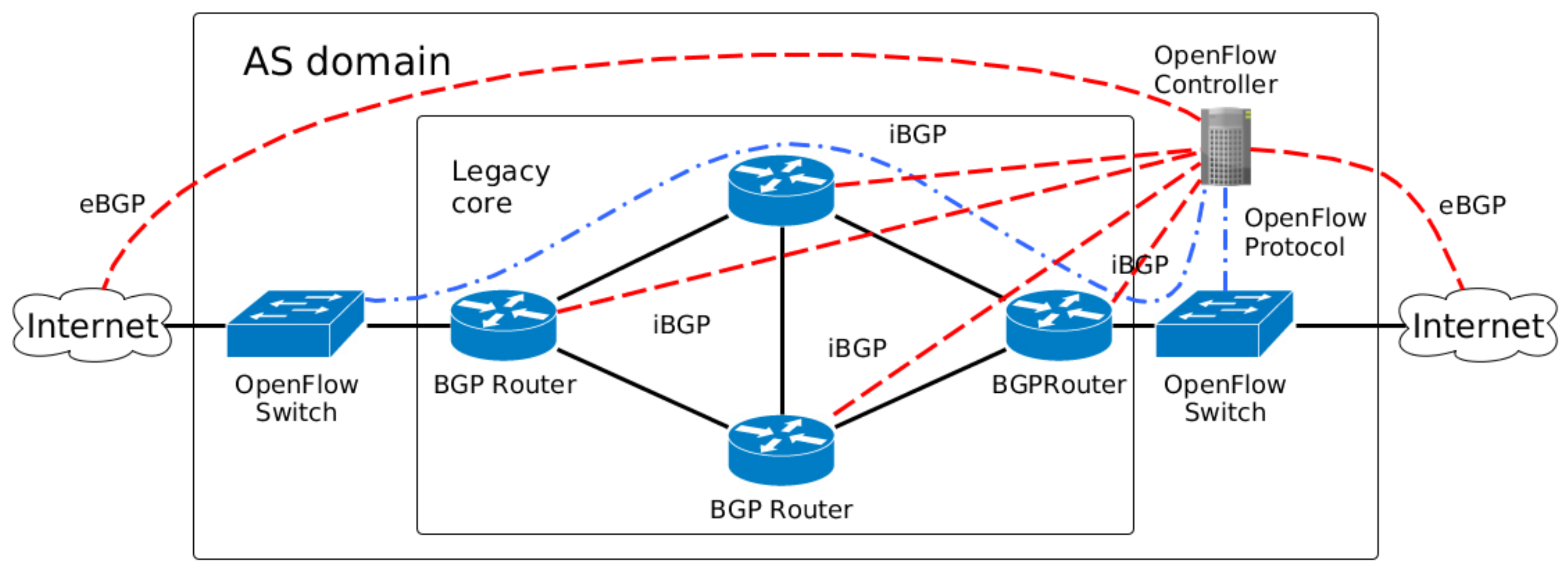
Figure 2.
AS domain composed of only OpenFlow switches.

Figure 3.
The proposed architecture described by the application, control, and data planes of SDN architecture.
Figure 3.
The proposed architecture described by the application, control, and data planes of SDN architecture.
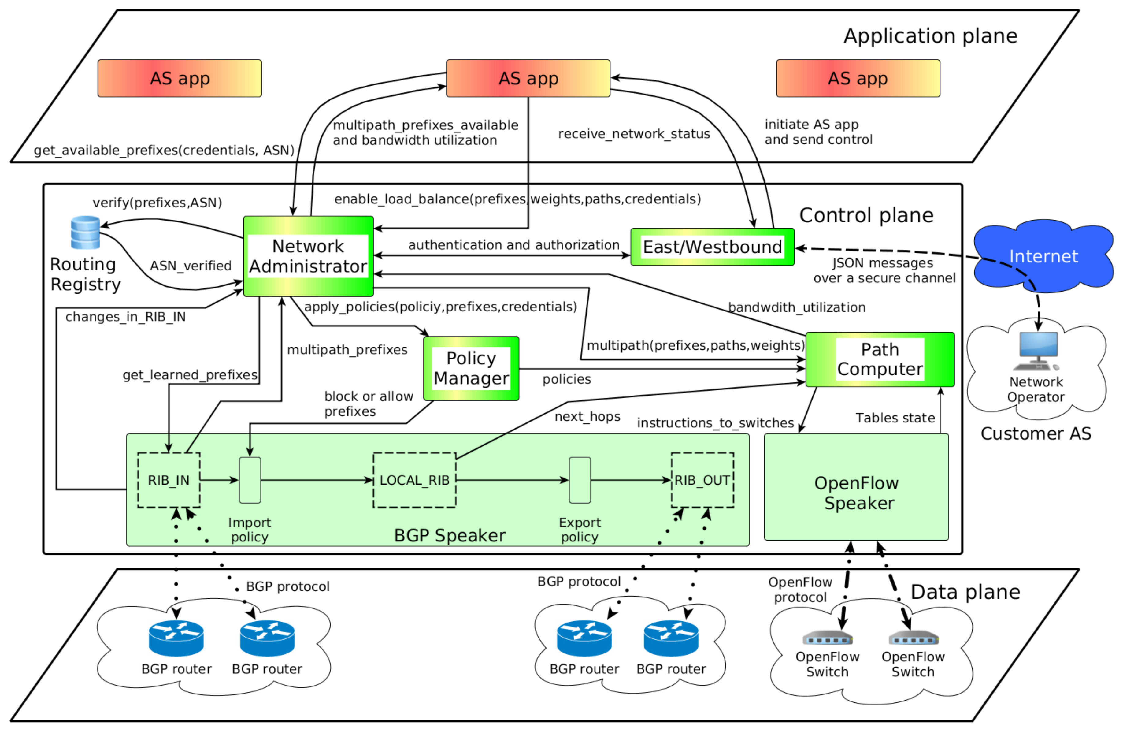
Figure 4.
The total number of multi-homed stub ASes is common in recent months of the Internet.
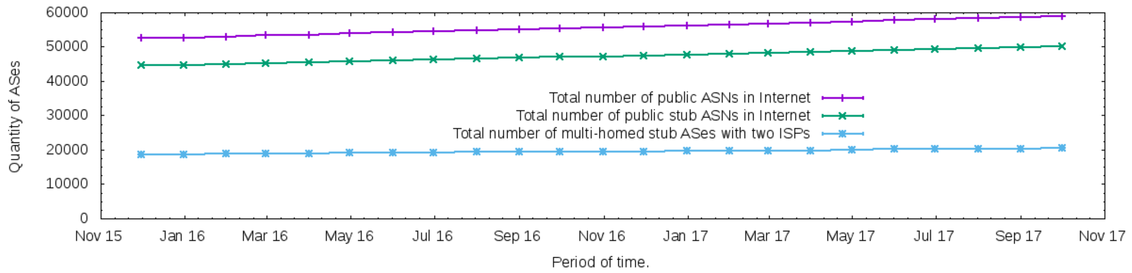
Figure 5.
The topology adopted.
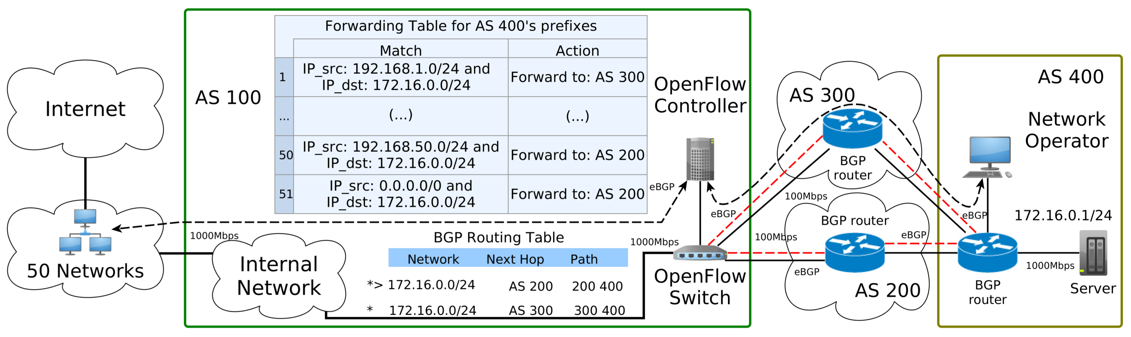
Figure 6.
BGP behavior for network traffic to the server 192.168.0.1/24 in AS 400.

Figure 7.
Random load balancer results.
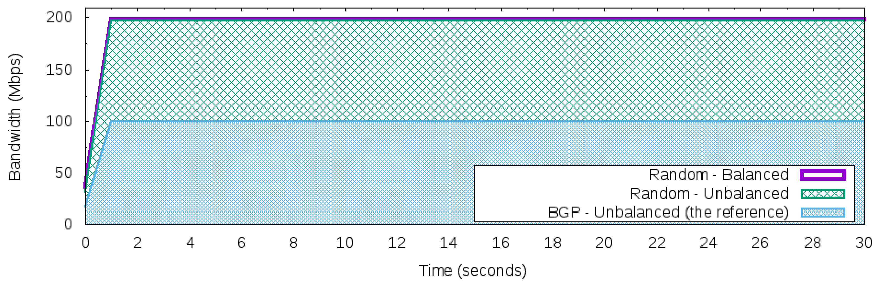
Figure 8.
Round-Robin load balancer.
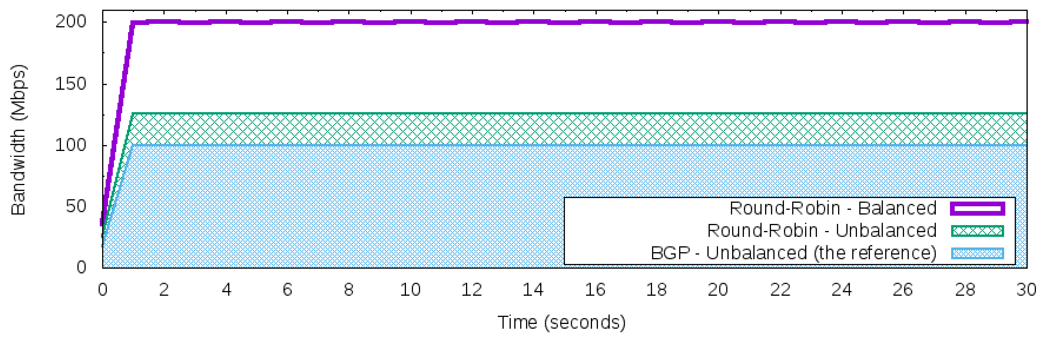
Figure 9.
Round-Robin load balancer with the threshold.
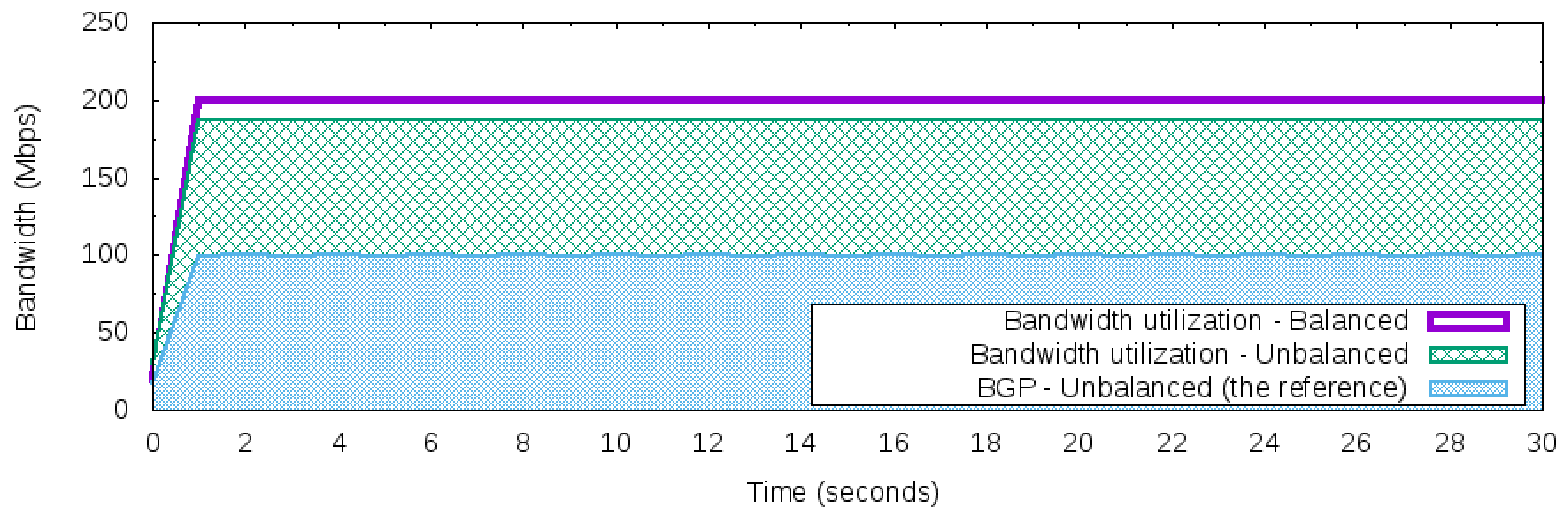
Figure 10.
The average of multiple measurements for the network traffic during a link failure around the 15th second with a confidence interval of 95%.
Figure 10.
The average of multiple measurements for the network traffic during a link failure around the 15th second with a confidence interval of 95%.

Figure 11.
An execution of link failure in the 15th second.

Figure 12.
Details of network traffic for the link failure around the 15th second.

Figure 13.
The potential number of customers affected by the proposed architecture deployed on the Internet.
Figure 13.
The potential number of customers affected by the proposed architecture deployed on the Internet.
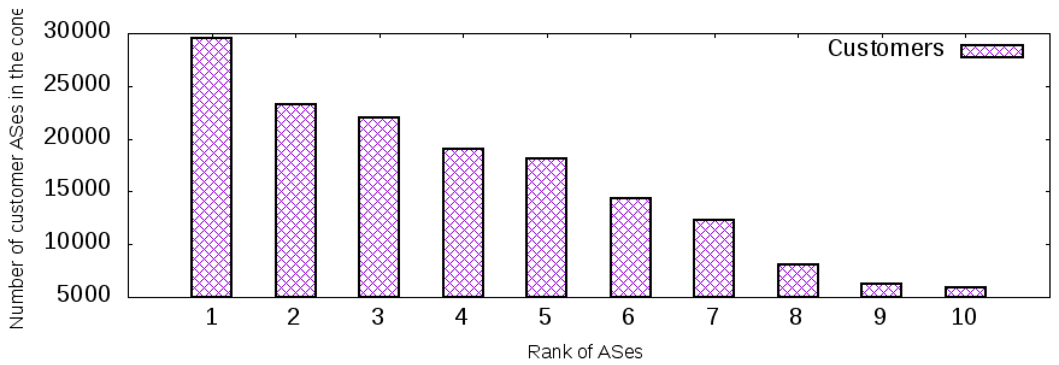
Table 1.
Flow table and group table for the OpenFlow Switch using OpenFlow Fast Failover Group Table.

Flow table at OpenFlow Switch.
| Match Fields | Instruction |
|---|---|
| IP_src:192.168.1.0/24 and IP_dst:172.16.0.0/24 | Group1 |
| IP_src:192.168.2.0/24 and IP_dst:172.16.0.0/24 | Group1 |
| (...) | Group1 |
| IP_src:192.168.50.0/24 and IP_dst:172.16.0.0/24 | Group1 |
| IP_dst:172.16.0.0/24 | Group2 |
Group table at OpenFlow Switch.
| Group Identifier | Group Type | Action Buckets |
|---|---|---|
| Group1 | Fast Failover | Watch: AS 200 port; Outport: AS 200 |
| Watch: AS 300 port; Outport: AS 300 | ||
| Group2 | Fast Failover | Watch: AS 200 port; Outport: AS 200 |
Table 2.
The bandwidth required to send the biggest message of the network state using the communication mechanism of the proposed architecture.
Table 2.
The bandwidth required to send the biggest message of the network state using the communication mechanism of the proposed architecture.
| Interval | Uncompressed (in Kbps) | Compressed (in Kbps) |
|---|---|---|
| 0–1 | 4472 | 292 |
| 0–5 | 894 | 58 |
| 0–10 | 447 | 29 |
| 0–15 | 298 | 19 |
| 0–20 | 223 | 14 |
© 2018 by the author. Licensee MDPI, Basel, Switzerland. This article is an open access article distributed under the terms and conditions of the Creative Commons Attribution (CC BY) license (http://creativecommons.org/licenses/by/4.0/).
Share and Cite
MDPI and ACS Style
Silva, W.J.A. An Architecture to Manage Incoming Traffic of Inter-Domain Routing Using OpenFlow Networks. Information 2018, 9, 92. https://doi.org/10.3390/info9040092
AMA Style
Silva WJA. An Architecture to Manage Incoming Traffic of Inter-Domain Routing Using OpenFlow Networks. Information. 2018; 9(4):92. https://doi.org/10.3390/info9040092
Chicago/Turabian StyleSilva, Walber José Adriano. 2018. "An Architecture to Manage Incoming Traffic of Inter-Domain Routing Using OpenFlow Networks" Information 9, no. 4: 92. https://doi.org/10.3390/info9040092
Note that from the first issue of 2016, this journal uses article numbers instead of page numbers. See further details here.