Article

Machining Duplex Stainless Steel: Comparative Study Regarding End Mill Coated Tools

1
ISEP (School of Engineering, Polytechnic of Porto), Porto 4200-072, Portugal
2
INEGI (Instituto de Ciência e Inovação em Engenharia Mecânica e Engenharia Industrial), Porto 4200-465, Portugal
*
Author to whom correspondence should be addressed.
Coatings 2016, 6(4), 51; https://doi.org/10.3390/coatings6040051
Submission received: 31 August 2016 / Revised: 9 October 2016 / Accepted: 12 October 2016 / Published: 26 October 2016
(This article belongs to the Special Issue Coatings for Cutting Tools)

Abstract

:
The difficulties in the machining of duplex stainless steel are well known. However, research on this matter is rather limited. Suppliers offer quite different cutting tools for the same raw material, with end mills of two, three or even four knives and a huge number of distinct coatings, some of them under commercial brands, making it difficult to assess the advantages they offer. Furthermore, there is a remarkable difference among the several types of duplex stainless steel available nowadays on the market. The present work intends to assess the machining performance of different tools, analyzing the behavior and wear mechanisms with two different cutting lengths, keeping constant the machining trajectory. Some other parameters were also kept constant, such as cutting speed, depth of cut and cutting width, as well as feed per tooth. The machining process was carried out under lubricated conditions, using an emulsion of 5% oil in water. Tools provided with a different number of teeth and surface coatings were tested, analyzing the wear behavior of each cutting length using scanning electron microscopy, trying to identify wear performance and how each coating contributes to increased tool life. The surfaces produced were also analyzed by means of profilometry measurements, correlating tool wear and part surface roughness. This comparative study allows determining the advantages of different tools relative to others, based on coatings and tool geometry.

1. Introduction

Machining remains one of the most employed processes in the world’s metalworking context. The aeronautics, naval and automobile industries are, probably, the economic sectors that most demand this kind of process through the engineering of parts included directly and indirectly in aircrafts, ships, trucks, buses and cars. Machining processes are necessary when surface quality is one of the main requirements demanded by customers or designers. However, competitiveness is a key factor in such industries, requiring accurate and extremely efficient equipment. Indeed, the available equipment on the market has continued to grow, becoming increasingly sophisticated and allowing an improved accuracy [1], answering to the need of the market for complex organic shapes and high surface quality.
Researchers have contributed significantly to this development, devoting their efforts to explaining many of the machining related phenomena, anticipating market needs and studying the best ways to increase production and improve products through tooling improvements, more accurate machining parameters, optimized machining trajectories, and so on.
With regards to the cutting process, mechanical work developed is converted into plastic deformation, creating friction between the tool and workpiece, resulting in heat generation [2]. Increasing the tool temperature causes materials to become softer and wear increases rapidly, reducing the tool life and decreasing the machining efficiency and the accuracy attained. Some experiments suggest that tool temperature rises as speed machining increases [3,4] in continuous cutting processes. However, Palmai [5], studying the interrupted cutting characteristics of the milling machining process, though not directly supported by experimental work, suggested that temperature can diminish as speed machining increases. Many studies have been carried out trying to optimize the parameters set for each material [6,7,8]. Rawangwong et al. [7], studying the main factors that affect the surface roughness of a semi-solid AA7075 alloy in face milling, suggested that feed rate ratio and cutting speed are the principal factors, whereas the depth of cut does not influence the surface quality. Furthermore, the same authors stated in the same work that higher cutting speed and lower feed rate tend to decrease the surface roughness. Zhang et al. [8] concluded as well that cutting speed and feed rate are the main factors influencing the surface roughness, rather than the depth of cut, in the milling process. A similar study has been carried out by Sai et al. [9] using as sample materials carbon steel and duplex stainless steel, concluding that a very slow cutting speed leads to build-up edge (BUE) formation, resulting in poor surface quality. They showed that a cutting speed of between 220 and 440 m/min achieved the best roughness surface values for small feed rate. An increase in the surface micro hardness and tensile residual stresses was also registered with higher values of cutting speed and feed rate.
The correlation among the parameters of surface integrity and fatigue life of machined components has also been studied. Li et al. [10] focused on the Inconel 718 milling process, studying the relationship between tool wear, fatigue life and surface integrity, concluding that more tool wear generates low surface roughness, and, with tool wear up to VB = 0.2 mm (VB, width of the flank wear land), no fatigue took place in up to four million cycles on the machined samples. Furthermore, considering end mill tools provided with PVD coated inserts, the roughness in the step-over direction was more pronounced than in the feed direction.
Stability during a machining process is a key factor in obtaining lower surface roughness and accurate products. Regarding the milling process, Stepan et al. [11] have studied the milling process stability using three different milling tools (conventional, variable helix and serrated milling tools). By means of semi-discretization and multi-frequency solution, the authors concluded that serrated milling tools provided the best contribution to cutting stability, despite this type of tool being used essentially in roughing operations, whereas the optimized variable helix end mill tools are more adequate for finishing operations, providing a better result in terms of stability than conventional ones.
The cost, quality and lead-time of the plastic products are directly influenced by the mould industry, which is based essentially on machining processes. When creating large mould cavities, milling operations are one of the most necessary means utilized [12,13], however, the surface roughness usually required by this industry cannot be achieved solely by this process [14]. The need to involve hand polishing operations is required, despite the use of High Speed Machining (HSM) and sophisticated tool path trajectories created through Computer Aided Manufacturing (CAM) software. Souza et al. [12] have stated that a correct selection of tool paths can save 88% of machining time and cut 40% of mould machining costs, when compared with a poor strategy option.
Denkena et al. [15] recently studied the influence of cutting edge geometry in tough milling operations on hardened steel moulds, trying to overcome the thermo-mechanical stresses developed on tools. The main goal of these authors was to decrease tool friction and wear by changing the flank face geometry. Simulations were made, which allows the provision of tools with undercut geometries, whereby an increase in tool life and a decrease in induced residual stress on machined parts can be observed.
Coatings have proven to be an attractive way to extend tool life by increasing surface hardness, acting in addition to other crucial parameters concerning tool work such as: decreasing the friction between tool and part; creating a thermal barrier between the surface and the hard metal substrate and allowing a better surface temperature distribution by dissipating the heat generated during tool contact with chips and machined part [16,17]. Thus, tool coating requirements are large and of high importance. Tool manufacturers started using the conventional TiN, however, this coating was not sufficient to solve all the previously mentioned problems, hence, multilayered coatings started to be developed in order to improve tool performance. Nowadays, tools recently introduced on the market present three or more layers, each one with specific functions, in order to satisfy all the requirements.

2. Materials and Methods

The raw material chosen to be machined for this study was a CD4MCuN duplex stainless steel (material specification: ASTM A890, Werkstoff-Nr. 1.4517 or EN 10283, ARSOPI, Vale de Cambra, Portugal). It is composed of a dual phase microstructure of both austenite and ferrite in similar amounts. The chemical composition given by the supplier for this batch of steel was (wt %) C 0.03%, Si 0.41%, Mn 1.48%, P 0.02%, Cr 25.41%, Ni 6.08%, Mo 2.91%, Cu 3.30%, Nb 0.01%, V 0.02%, W 0.04%, N 0.19%, Co 0.08% and Fe 60.02% [18]. It is sold in a heat treated state (quenched at 1135 °C and water cooled) and according to the supplier has a yield strength (0.2%) and an ultimate tensile strength of 489 MPa and 797 MPa, respectively (in accordance with ISO 6892-1 [19]), as well as hardness of 267 HB (ISO 6506-1 [20]). Among several different material properties, some of the most important are its high mechanical strength (approximately twice as much as the more common ASTM 304 and 316 stainless steels), good corrosion and pitting resistance, good toughness, good weldability and ease of fabrication. Typical applications are the construction of chemical equipment and tubbing, pressurized tanks and vessels, heat exchangers, cellulose and paper fabrication, sea water processing, etc. This duplex stainless steel is thought to be of interest due to the fact that numerous flanges and accessories, which require machining, are made from this material and information surrounding this topic is scarce. A round bar with a diameter of 60 and 300 mm in length was sufficient for all testing trials.
The machining operations were performed on a 3-axis CNC machine (brand/model: Haas VF2 vertical machining center, Hass Automation, Inc., Oxnard, CA, USA). A 3-jaw self-centering chuck (brand/model: Bison 3575, BISON-BIAL, S.A., Bielsk Podiaski, Poland) was mounted to the machine’s work table (in accordance with standard DIN 6350 [21]), guaranteeing the exact same positioning of the round bar between each trial. The use of a hydraulic tool holder (brand/model: WTE DIN 69871-AD/B [22], WTE Präzisionstechnik GmbH, Kempten, Germany) was necessary as this type of system minimized unwanted vibrations during testing. Figure 1 illustrates several components utilized during testing.
The comparative study is based on the wear analysis of four different milling tools advertised as being appropriate for milling duplex stainless steels. The milling tools used all have in common a cutting diameter of 4 mm, a 6 mm shank diameter and a coated hard metal substrate. Milling tools with a 4 mm shank diameter were initially tested, however, they proved to be too fragile, suffering premature breakage. Table 1 lists the characteristics of all four different selected end mills.
For easier reading and referencing, tools will be referred to by their manufacturer’s name, followed by the number of cutting flutes and composition of coating (e.g., Dormer Z2 AlCrN) instead of their complete designation.
Besides analyzing the influence of coatings on wear behavior, the number of cutting flutes was also changed to investigate its effect on tool longevity. Usually, the amount of cutting flutes influences the ease of chip removal, so it is common sense to use tools with less cutting flutes in slotting operations and tools with more flutes in side milling operations. When chip removal is difficult, a buildup edge may appear on the tool.
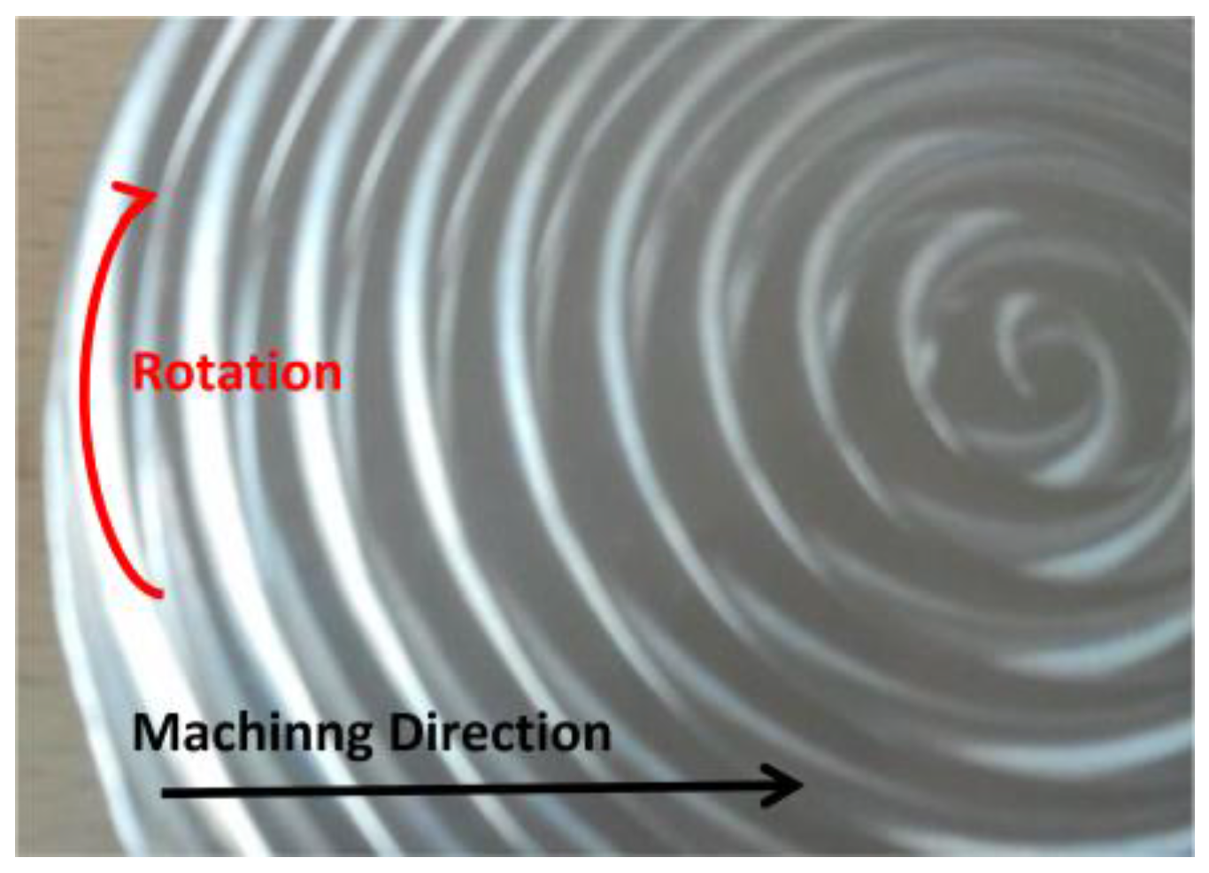
In order to evaluate the wear of each tool, a simple roughing machining strategy was created to ensure repeatability of test conditions. Based on the round format of the bar, a spiral path was created to optimize cutting length, as can be seen in Figure 2. The tool begins side milling on the outer side of the stainless steel bar making its way to the center. A ramp plunge movement is used in the initial portion of the machining stage to create a gradual tool approach to the material, avoiding potential collisions.
All machining parameters remain the same throughout testing with the exception of the feed speed. As the number of cutting flutes changes from tool to tool, feed speeds are adjusted in order to ensure that feed per tooth speeds are similar. This allows similar cutting conditions on each cutting tooth, promoting equal working and wearing conditions. Spindle speed was established based on tool manufacturers’ recommendations and initial testing, ensuring a surface finish capable of being analyzed by the profilometer. Depth of cut and working engagement values were determined based on trial and error. Initial trials using 1 mm depth of cut were tested, however, this depth proved to be excessive for the combination of small tool diameter and high hardness steel, needing to be reduced to 0.5 mm. Recommended working engagement values are usually 60%–70% of tool diameter, so 3 mm was chosen for this parameter as smaller values may promote rougher surface finishing and decrease tool life span.
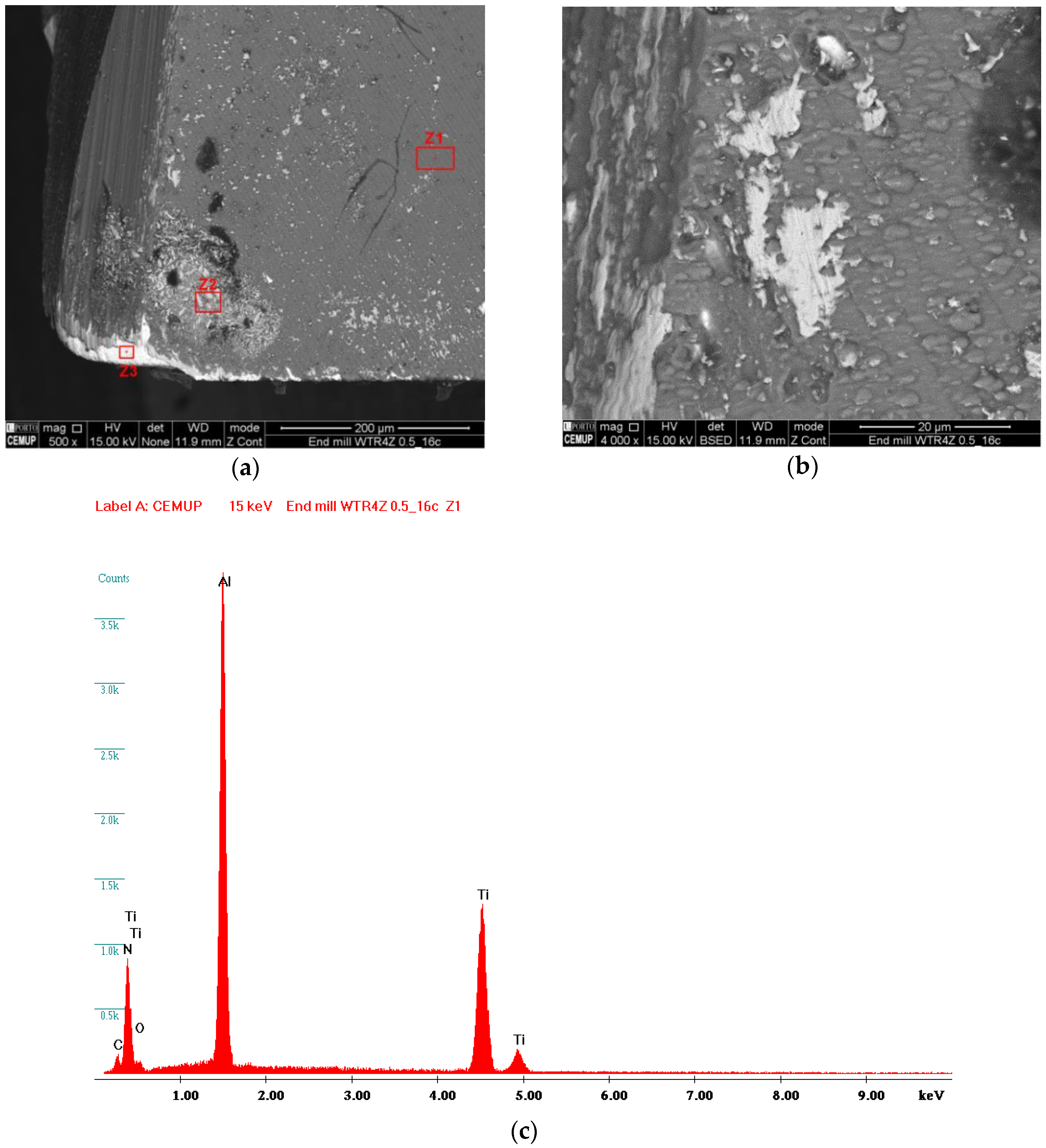
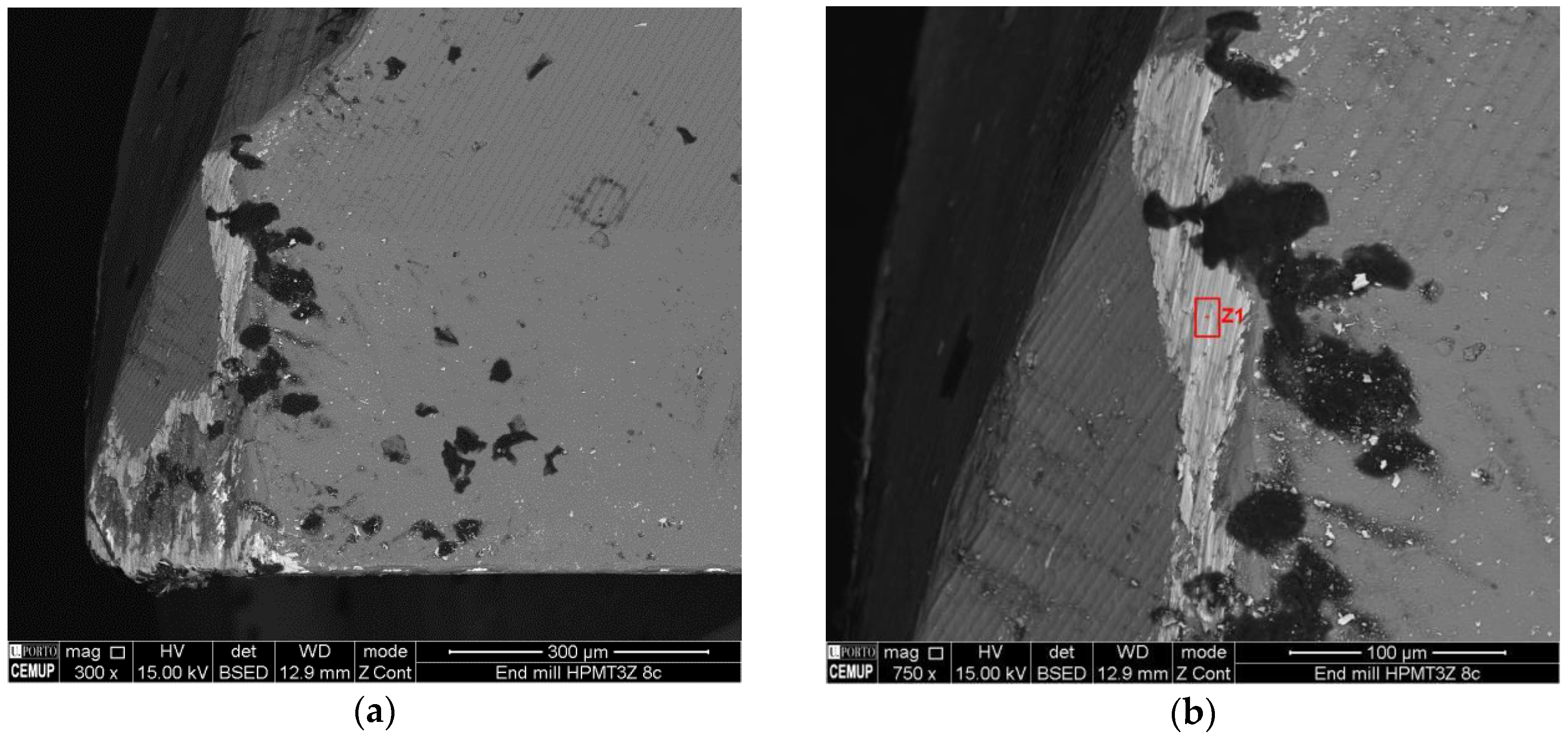
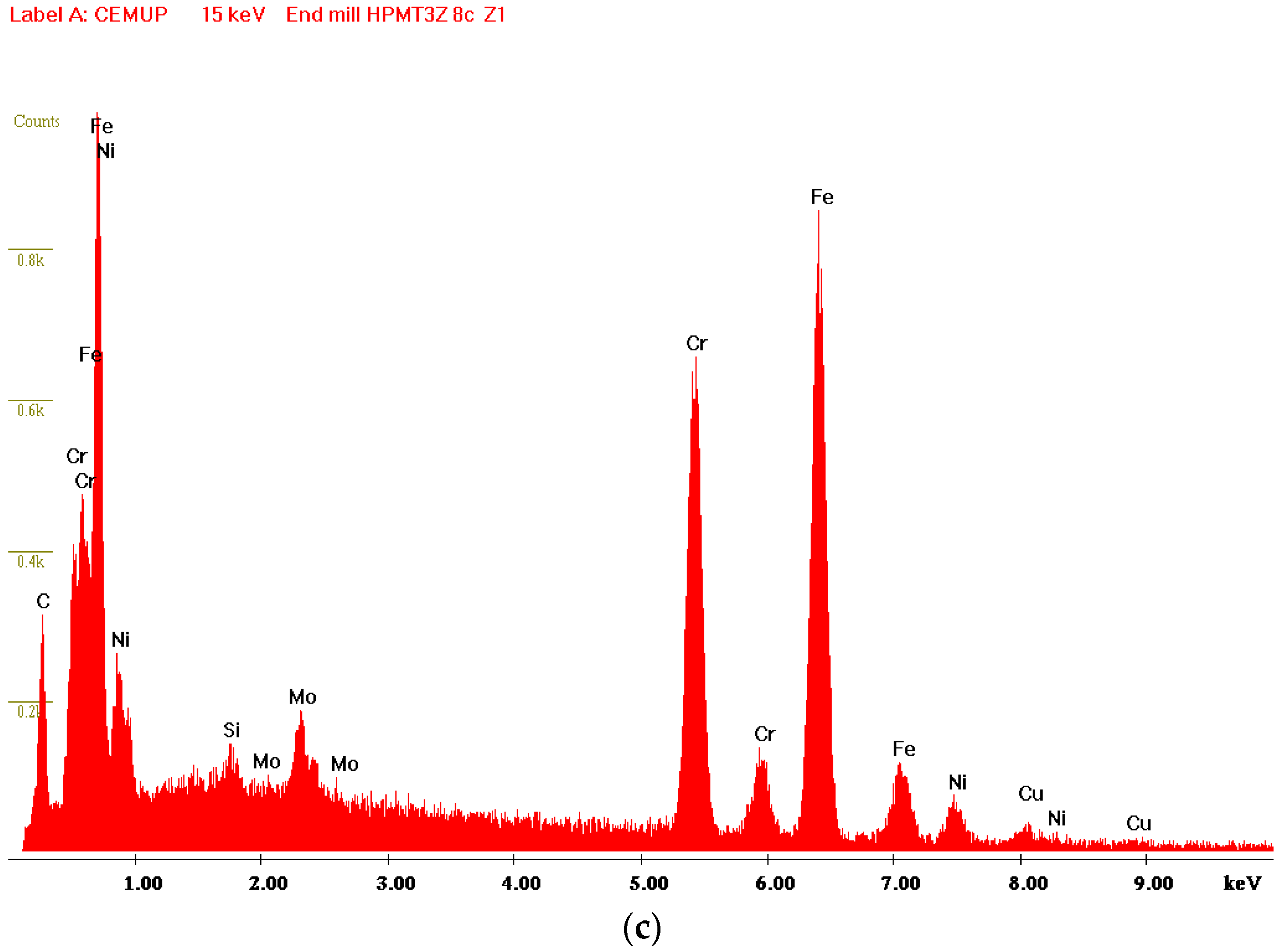
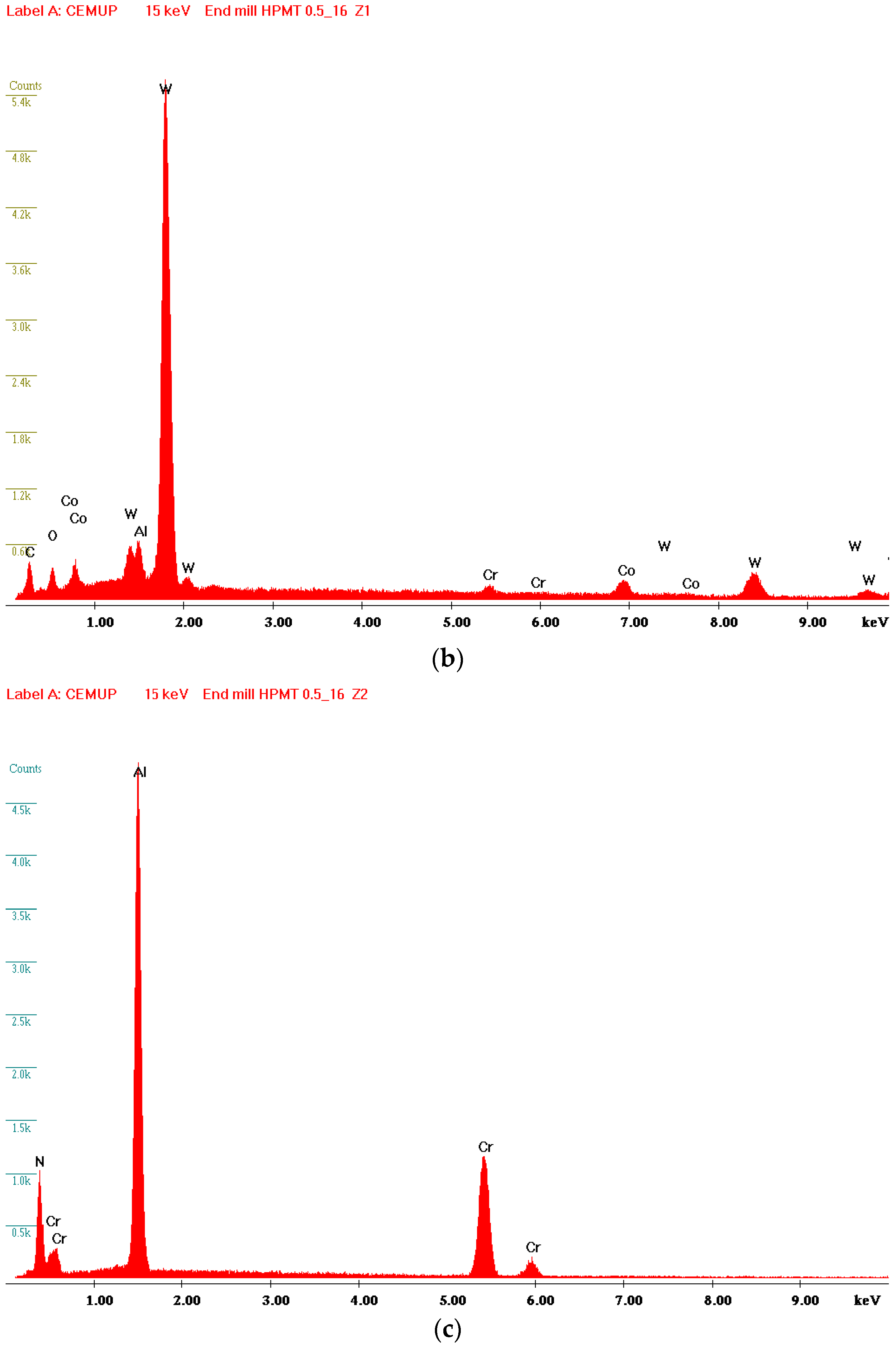
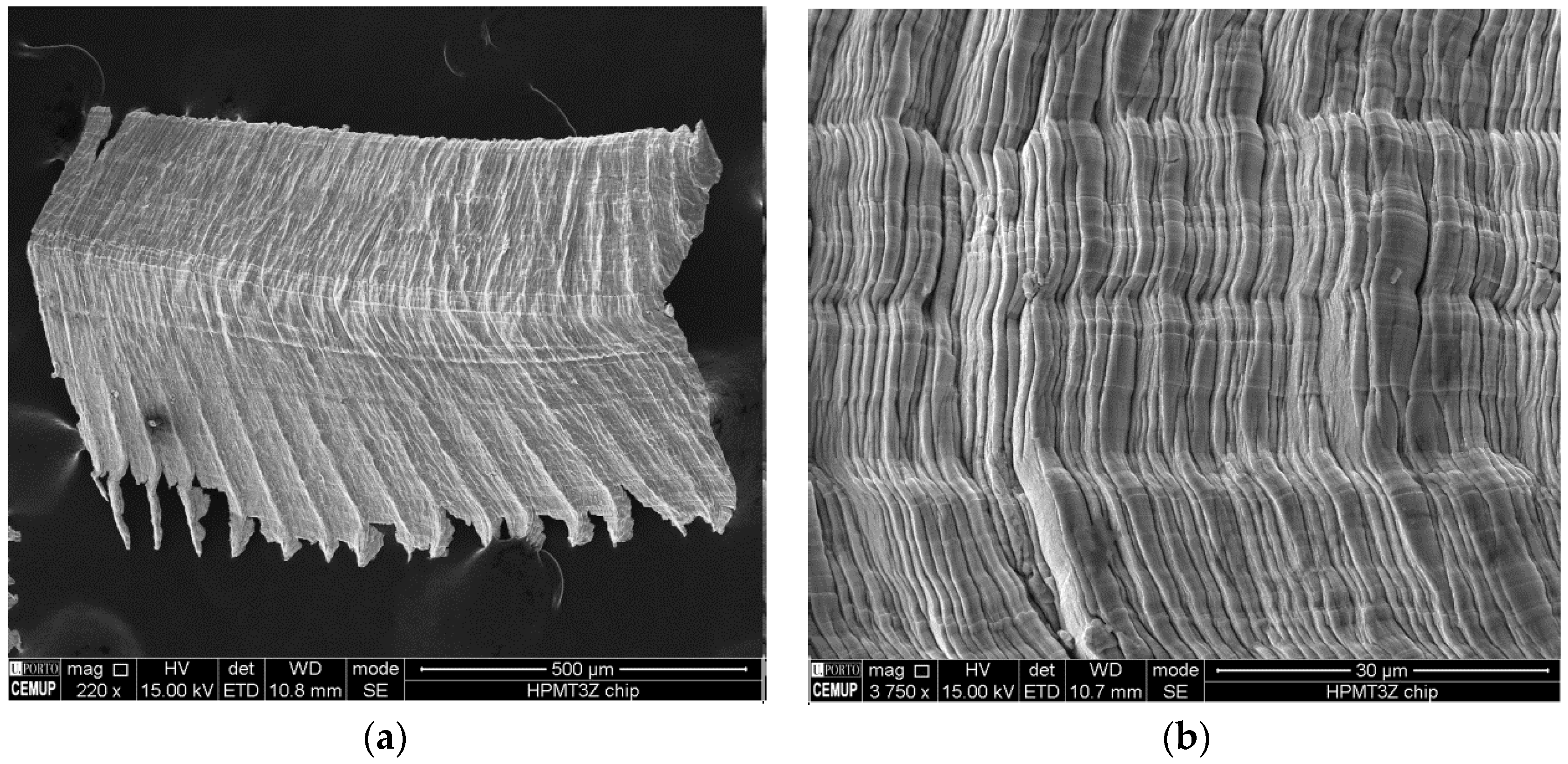
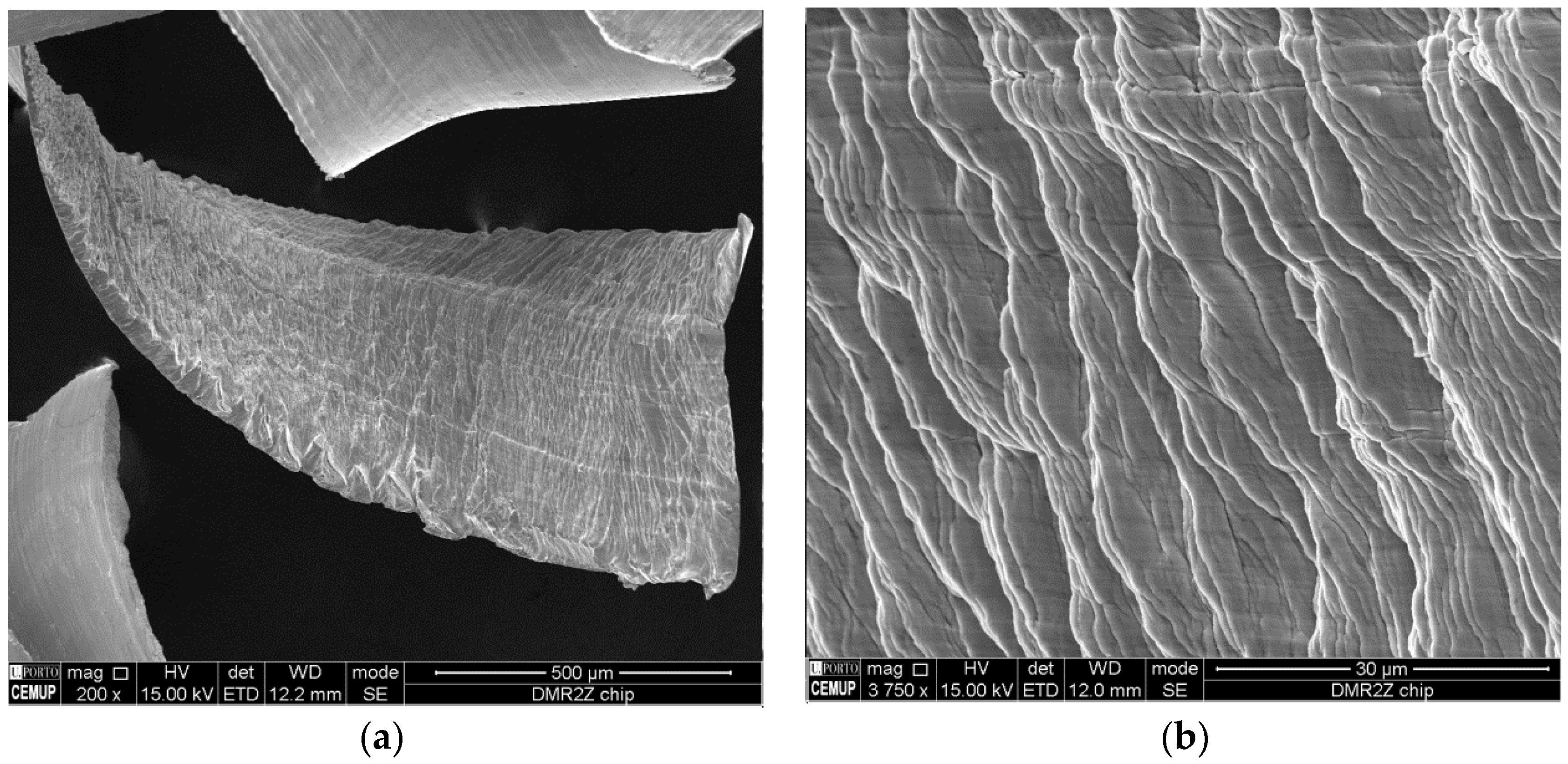
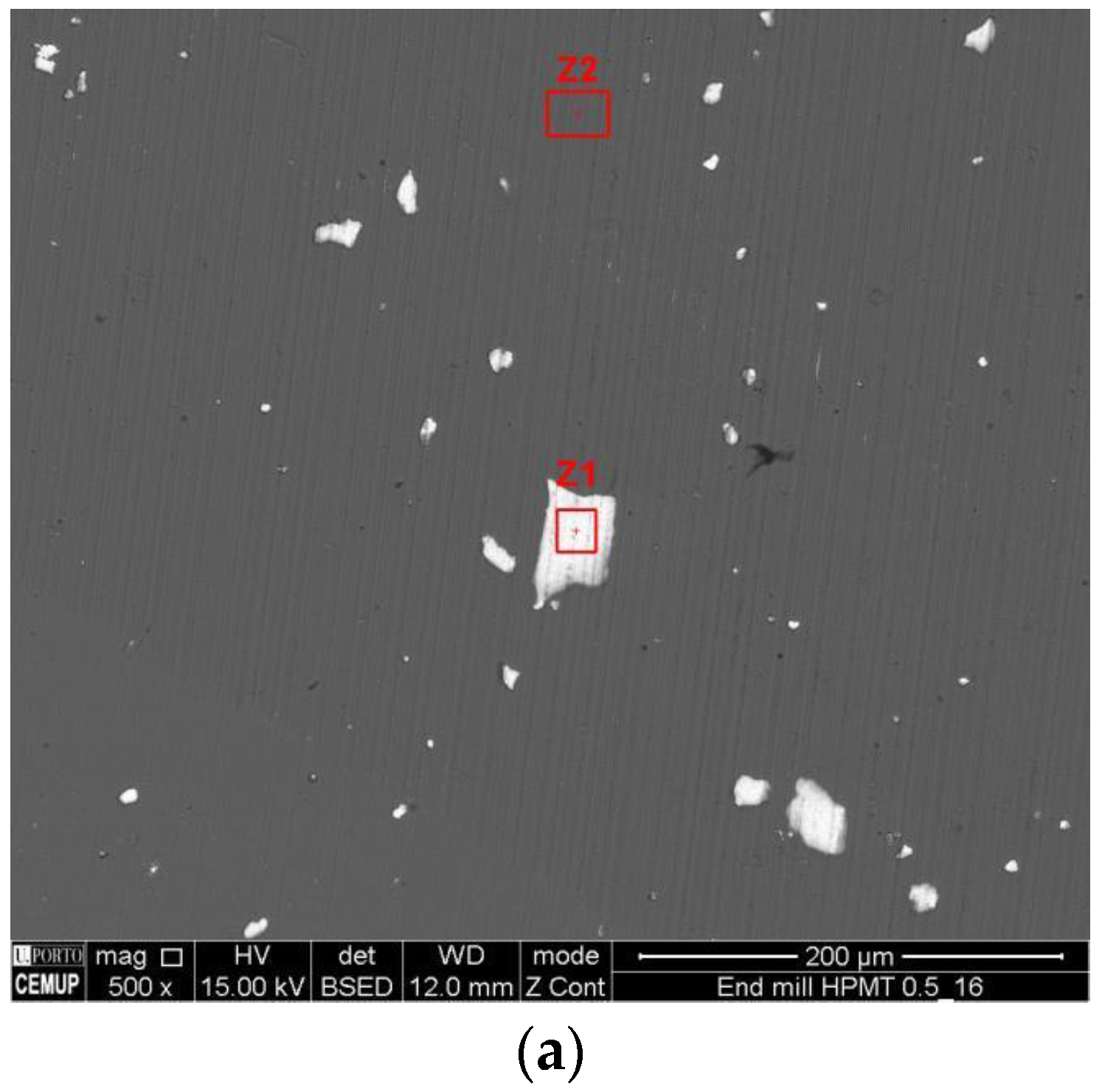
The surface wear of each tool was evaluated using a SEM microscope provided with an EDS (Energy-Dispersive X-ray Spectroscopy) system (EDAX X-ray micro-analysis). For this study, the equipment chosen was a FEI Quanta 400 FED SEM (FEI, Hillsboro, OR, USA). Several global and close up images of the worn edges were registered. Per tool, two global images are shown, one taken with secondary electron imaging and the other with retro diffused electron imaging. Whenever areas of discontinuities (promoted either by loss of coating or adhesion of external materials) were detected, an EDS analysis was made to determine the chemical composition of that unknown area. Close up images of each cutting flute were taken to evaluate and measure flank wear present on the cutting edges. These measurements are designated by the abbreviation VB.
Table 2 sums up all the machining parameters used with each tool. Cutting fluid emulsion was used during all machining operations, being composed of a mix of 5% oil in water.
The analysis of post-machined surface roughness was achieved using a surface profilometer (brand/model: Mahr Perthometer M2, MAHR, GmbH., Gottingen, Germany) provided with a diamond stylus tip with a 2 µm radius (ISO 4288:1996) [23]. Two different roughness readings were taken, one in a radial orientation and the other in a tangential orientation, utilizing a cutoff value of 0.8 mm. Arithmetic mean surface roughness (Ra), surface roughness depth (Rz(DIN)) and maximum height of the roughness profile (Rmax) were registered for each machined surface after each experimental run. Ra is an arithmetical mean average and may not truly represent the roughness of the surface. Rz is the sum of the height of the largest peak plus the depth of the deepest valley, inside the measured length. Rmax is the height of the largest peak or the depth of the deepest valley encountered in the measured length. With radial readings it is possible to evaluate the surface roughness left by the tool feed marks (boundary lines between tool passes) while with tangential readings it is possible to verify the surface roughness in between these lines. For each tool trial, six measurements were taken (three in a radial direction and three in a tangential direction), allowing to determine a mean-value that better represents the overall roughness of the machined surface.

3. Results

Having concluded all experimental trials, the wear suffered by each tool was evaluated by measuring the surface roughness on each machined part and by a microscopically analyzing the cutting edges of each tool. Average roughness values were calculated to represent the overall level of roughness present on each surface. These results allow evaluating the specific performance of each tool.

3.1. Machining Strategy

The adopted machining strategy was based on the premises discussed previously. For every trial, each end milling tool will repeatedly machine a pre-determined quantity of metal (cycle). One cycle corresponds to a completion of a machining pass, with a depth of cut of 0.5 mm, starting on the outer side of the stainless steel bar and making its way to the center. Each tool will be evaluated after completing one run of eight machining cycles, which equals to a total machining distance of 7.5 m. Another set of tools will be tested during 16 cycles, totalizing a machining distance of 15 m.

3.2. Map of Experiments

In order to pursuit the main goals of this work, a map of experiments was drawn, which can be seen in Table 3, showing the different tools used in the comparative study as weel as the selected machining parameters.

3.3. Experimental Results

3.3.1. Walter 4Z TiAlN—Roughness and SEM Results

The 8 cycles run trial for the Walter 4Z TiAlN end mill produced unexpected surface roughness results. When compared to the values obtained by the 16 cycles run, the shorter trial returned higher roughness values. There seems to be no significant explanation for these results (values can be seen in Table 4).
The obtained radial Rz roughness values for the 8 cycles trial are lower when compared to the 16 cycles run, meaning that the machined surface has a smaller profile height between surface peaks and valleys. This translates in to a smoother and stronger machined surface with better dimensional and mechanical properties.
Due to its configuration (4 cutting flutes), coating and toughness, it is an ideal tool for machining harder materials, as the one used in this experiment.
Although radial roughness values increased from 8 to 16 cycles (as expected), the difference between both is of low significance. This leads to the assumption that wear evolution is slow, when compared to other tools, translating into a longer tool life.
The SEM analysis of the tool surfaces reveals that, for the shorter machining cycle (shown in Table 5), tool wear is very low with a small VB value (flank wear), showing edge chipping as the only type of wear present. Its influence is of low importance as shown by the small roughness values discussed earlier. The images shown in Table 5 demonstrate the existence of several surface impurities.
When analyzing the results of the SEM analysis after 16 cycles (referring to Table 6), it is possible to observe VB values have increased, indicating further tool wear.
In Figure 3 it is possible to observe distinct areas, such as regions where the tool has lost its coating. This phenomenon is due to the natural occurring wear caused by friction and abrasion between the tool and the material being machined. It is also possible to observe white specs which are caused by the collision of metal shavings with the tool surface during machining operations. The area marked as Z1 shows a section with intact coating composed of titanium aluminium nitride. The marked Z2 area contains adhered material from the machined part, tool substrate material and several other impurities, being composed mainly of carbon, titanium, chromium, iron and manganese. The adhesion of these impurities may be related to the geometry of this end mill, as 4 cutting flutes hinder the ease of chip removal, promoting collisions between the tool and the built up material. The area marked as Z3 represents the tool substrate as the EDS analysis displays elements coherent with the composition of hard metal.

3.3.2. HPMT 3Z AlCrN—Roughness and SEM Results

Roughness results shown in Table 7 demonstrate no significant variation in terms of Ra roughness from one trial to the other. Rz roughness values for 8 cycles are relatively low, although worse than when compared to the previous Walter 4Z TiAlN end mill. The evolution of roughness values from 8 to 16 machining cycles clearly demonstrates an increase of surface roughness and loss of tool cutting quality. Tangential Ra and Rz values are in fact the highest values obtained across all tested tools, creating a coarser surface finish which can lead to loss of dimensional tolerance. Radial values position this tool in third place, which translates to a machined surface with noticeable feed marks.
Looking at the SEM analysis for 8 cycles, shown in Table 8, it is possible to observe foreign material adhered to the tool surface. As shown in Figure 4, the analysis of the adhered material shows that it is mainly composed of iron, nickel and chromium, consistent with the composition of stainless steel, confirming that the origin of this material is the machined part. This type of phenomena may lead to a large build up on the tool surface and consequently coating detachment.
In Figure 4, it is possible to closely view several distinct areas representing wear and material adhesion, as well as the EDS analysis for those areas.
When comparing flank wear between both trials, an increase of values is noticeable after 16 cycles of machining. For instance, the highest VB value for the 8 cycles run was 117.50 µm, while the 16 cycles run present a value of 380.00 µm. Nevertheless, the performance of this tool is acceptable bearing in mind its low acquisition price. These values can be seen in Table 8 and Table 9.

3.3.3. HPMT 4Z AlCrN—Roughness and SEM Results

Even though all machining and testing parameters where kept equal for all trials, the results obtained by this tool are somewhat unexpected. Seen in Table 10, the surface roughness produced after 8 cycles was the worst of all measured results. Regarding the 16 cycles run, the Ra radial roughness is, as well, the highest of the batch of experiments, delivering a machined surface of inferior quality. However, in terms of tangential Ra values, this tool delivered a surprisingly low surface roughness, being tied with the WALTER 4Z TiAlN end mill (best values measured across all experiments). When comparing these two tools, the HPMT 4Z AlCrN has a major price advantage, with the downside of having a shorter working life.
As referred to previously, the results obtained after 8 cycles indicate poor performance. When observing Table 11, it is possible to see that most cutting flanks suffered severe damage. The registered VB wear values after 8 machining cycles are the highest of all tools (exceeding in some cases 1 mm in length). The most plausible hypothesis for this phenomenon is the fact that the material being machined is not completely homogenous, containing localized areas with higher hardness values. These areas are essentially microstructures with different metallurgical phases. The existence of these heterogeneities can be seen, in Figure 5, being also possible to observe a dragging pattern on the surface of the machined part. This pattern was formed by the impact between the tool and the higher hardness areas and seems to be the main reason of wear in tools, being particularly noticeable during this trial.
When viewing the SEM images for the 16 cycles run (Table 12), it is possible to observe the loss of the flank edges. This type of wear caused higher radial Ra roughness values and led to more noticeable feed mark embossments.
In Figure 6a, which is a close up of cutting edge 1, it is possible to observe several white specs which indicate lack of coating. This phenomenon occurs when machined chips collide with the end mill and chisel away at the surface coating. EDS analysis in Figure 6b shows the composition of area Z1 as being perfectly coherent with the composition of the tool substrate (hard metal), indicating loss of coating. In the same manner, the Z2 area is composed mainly of aluminum and chromium, which are the elements that form the AlCrN coating.

3.3.4. DORMER Spectrum S812HA—Roughness and SEM Results

This tool returned low surface roughness values for the 8 cycles run (Table 13). Radial and tangential Ra and Rz values for this test were the lowest of all tested tools. This combination of factors leads to almost imperceptible feed marks on the surface of the machined part. On the other hand, the evolution in roughness values from 8 to 16 cycles indicates a rapid tool degradation, which may translate into low tool life/durability.
Bearing in mind that this mill just presents two cutting edges, the roughness values obtained after 16 cycles of machining can be considered reasonable. Lesser cutting knives signify higher working loads per knife (twice as much when compared to a 4-edge cutting mill), so the observed values should take into account this factor.
When taking an overall look at Table 13, it is possible to say that this tool creates good machined surface quality, especially for shorter machining paths. However, due to its high degradation rate, its longevity may be reduced.
In accordance with the previously discussed roughness results, the SEM analysis for an 8 cycles run (Table 14) illustrates that this tool does not present any major damage to its cutting edges. It is also noticeable that one cutting edge returns a higher VB value than the other edge. This situation is mainly caused by the fact that one of the cutting flanks executes an initial roughing cut, with a larger material removal rate, while the other edge executes a type of finishing pass, rectifying the previous cut. The loads applied to the secondary edge are smaller and consequently less severe.
As stated previously, in spite of this having a superior wear after 16 cycles, the work load completed by each cutting edge is higher than any other tool present in this experiment. Regardless of this fact, the tool generated a fairly satisfactory machined surface quality.
No EDS analysis was made as this tool did not show any major differences from the previous ones tested. Another small note that can be made is that due to its geometrical configuration, chip extraction is more easily accomplished, which consequently minimizes collision/adhesion of material to the tool’s cutting edges. This can be confirmed by the SEM imagery, showing a relatively low presence of white specs across the end mill surface, as can be seen in Table 15, where the tool wear can be observed and the probable causes of that wear are listed, as well as some possible solutions.

3.3.5. Chip Analysis for DORMER 2Z AlCrN and WALTER 3Z AlCrN End Mills

Chips generated by mill tools HPTM 3Z AlCrN and DORMER 2Z AlCrN were collected after the 8 cycles machining trials and observed under the SEM microscope. By observing Figure 7, it is possible to perceive differences between the chips created by each tool.
The chips created by the HPMT 3Z AlCrN end mill demonstrate a rougher and more irregular edge/rim. This geometry may be explained by the higher rake angle (less sharp) of this tool, which consequently generates higher friction loads between cutting edges and chips, and by the additional difficulty of chip extraction due to the increased number of cutting flutes. That said, the chip surface (seen in Figure 8) displays greater surface irregularities, indicating the existence of larger loads during extraction/ejection.
The chips originated by the DORMER 2Z AlCrN end mill demonstrate a cleaner and more uniform surface and rim edge. This is mainly due to its facilitated extraction and lower friction loads. In Figure 9, it is possible to observe the surface of the machined chip, demonstrating a lesser crushed surface mainly due to the smaller rank angle (sharper) and spaced out cutting flutes.

4. Discussion

In this section, a global analysis was done in order to establish which tools demonstrated superior performance and what lead to such results.
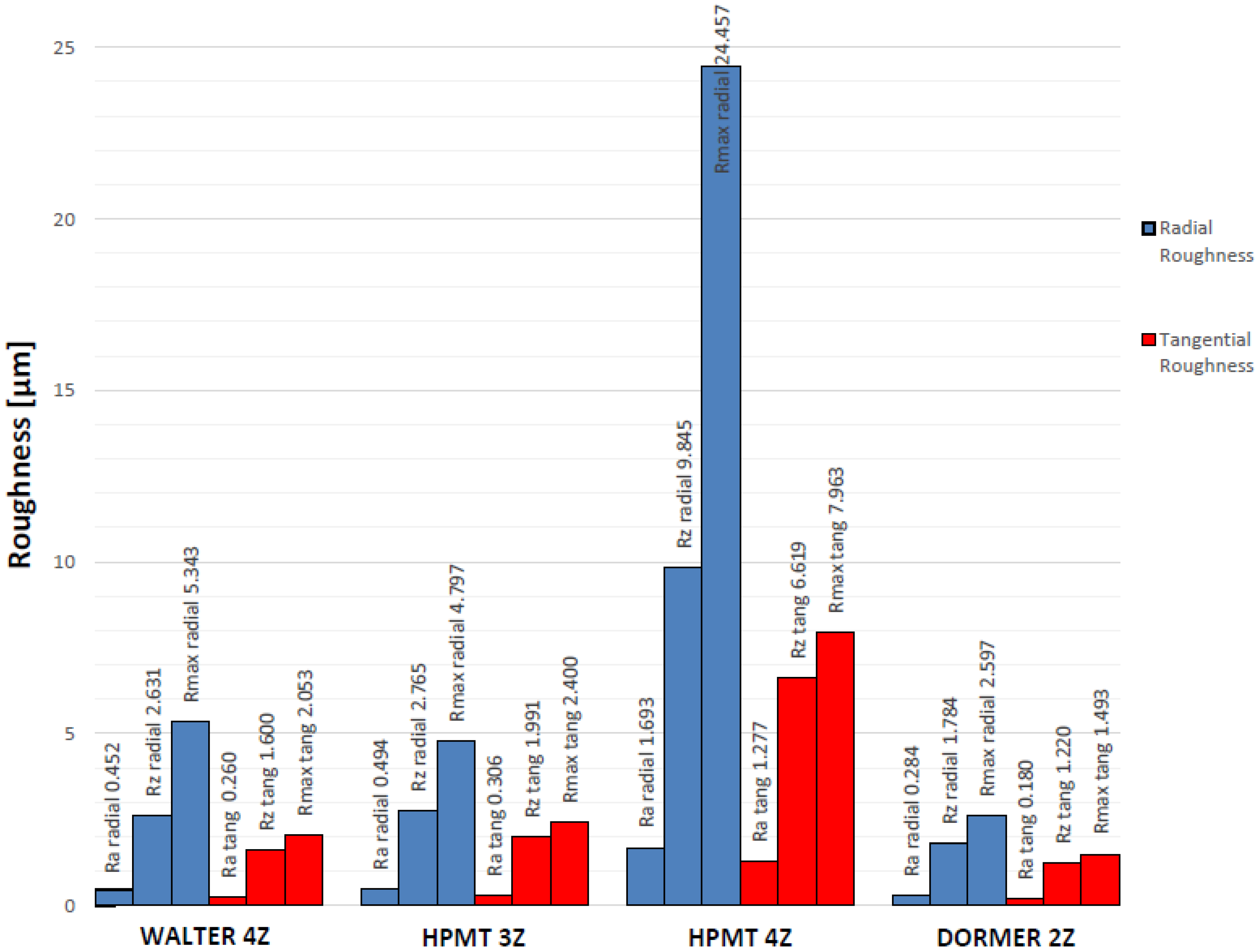
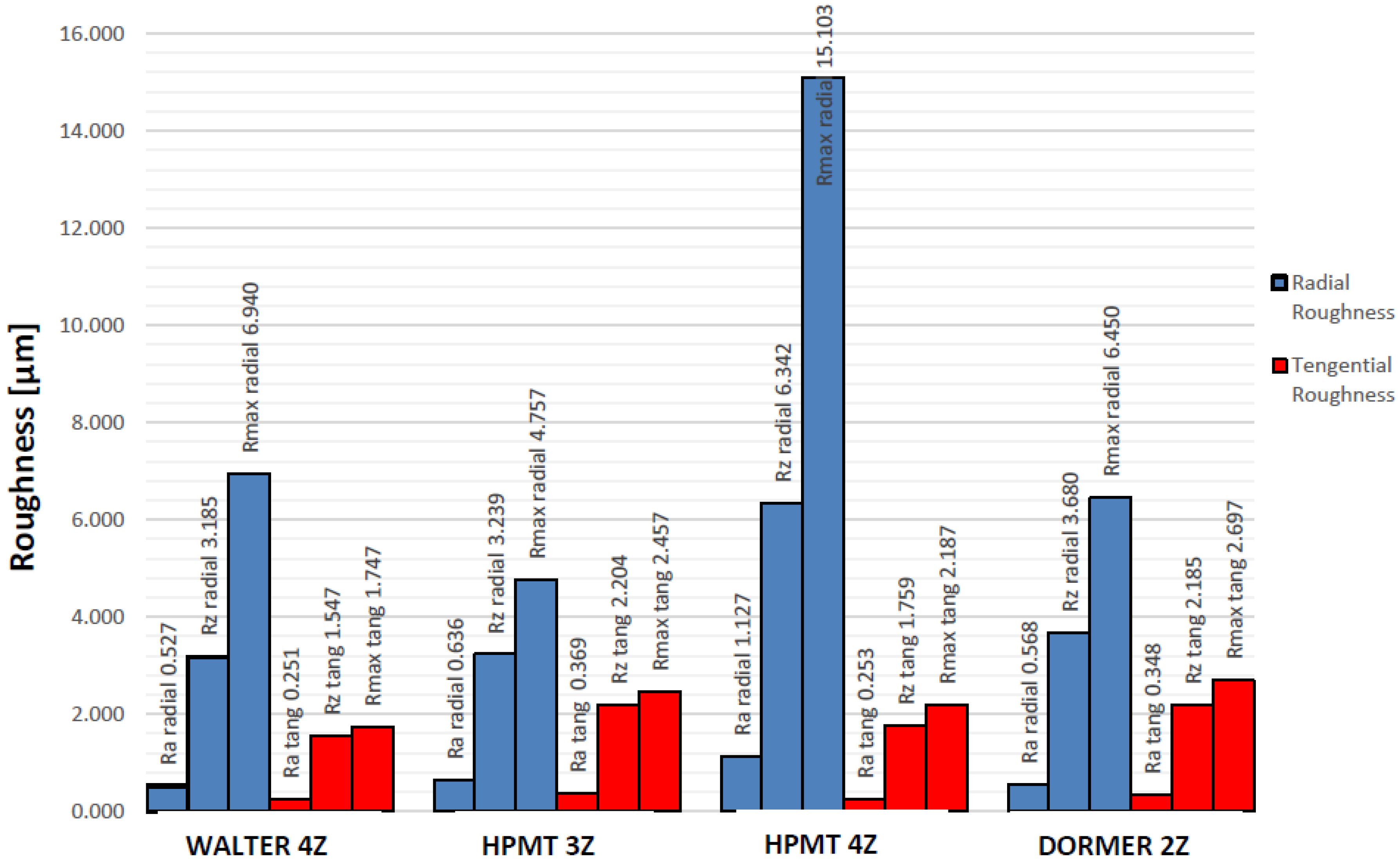
Depending on which tool was used and the length of the trial, several different roughness results were measured on each machined surface. The shorter 8 cycles trials presented lower roughness values, as expected. As seen in Figure 10, the tool which produced the lowest surface roughness for the shorter cycle run was the DORMER 2Z AlCrN end mill, having, as well, the least difference between radial and tangential roughness values. This indicates a more uniform surface without noticeable feed marks. The Rz values were also the smallest of all tests, indicating a low variation between surface peaks and valleys, which ensures longer part life with continued dimensional accuracy.
The WALTER 4Z TiAlN gave slightly higher roughness values for the 8 cycles when compared to the previous mentioned tool, however, it returned the most consistent global performance.
Regarding the HPMT 3Z AlCrN tool, reasonable roughness (including Rz) values were obtained, being the third best tool for the 8 cycles in terms of machining length.
End mill HPMT 4Z AlCrN performed poorly, returning very high values. This outcome was somewhat unexpected and, perhaps, may be a consequence of the excessive wear/damage suffered by the tool on the account of hardened material phases possibly present in the raw material. A possible manufacturing defect may also be speculated as the reason for such a rapid downfall.
Figure 10 also shows, in terms of radial roughness, an end mill which negatively stands out among the rest (HPMT 4Z AlCrN). While all other end mills showed similar Ra results, HPMT 4Z AlCrN mill revealed higher Ra radial roughness. As previously discussed, this tool suffered damage during the experimental trials, leading to a loss of material and edge sharpness of the cutting flutes. This phenomenon may explain the more noticeable feed mark embossments, leading to the larger radial Rz and Rmax roughness values.
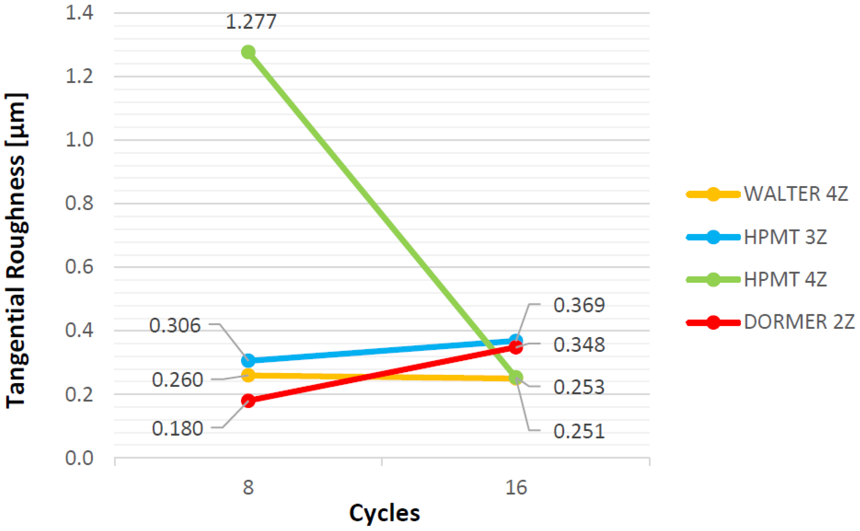
Tangential roughness values for the 16 cycles trials, shown in Figure 11, clearly demonstrate that WALTER 4Z TiAlN and HPMT 4Z AlCrN obtained the best results. The remaining tools present similar and satisfactory tangential Ra values, however, they exhibit higher Rz values which lead to a more irregular surface in terms of peak height and valley depth.
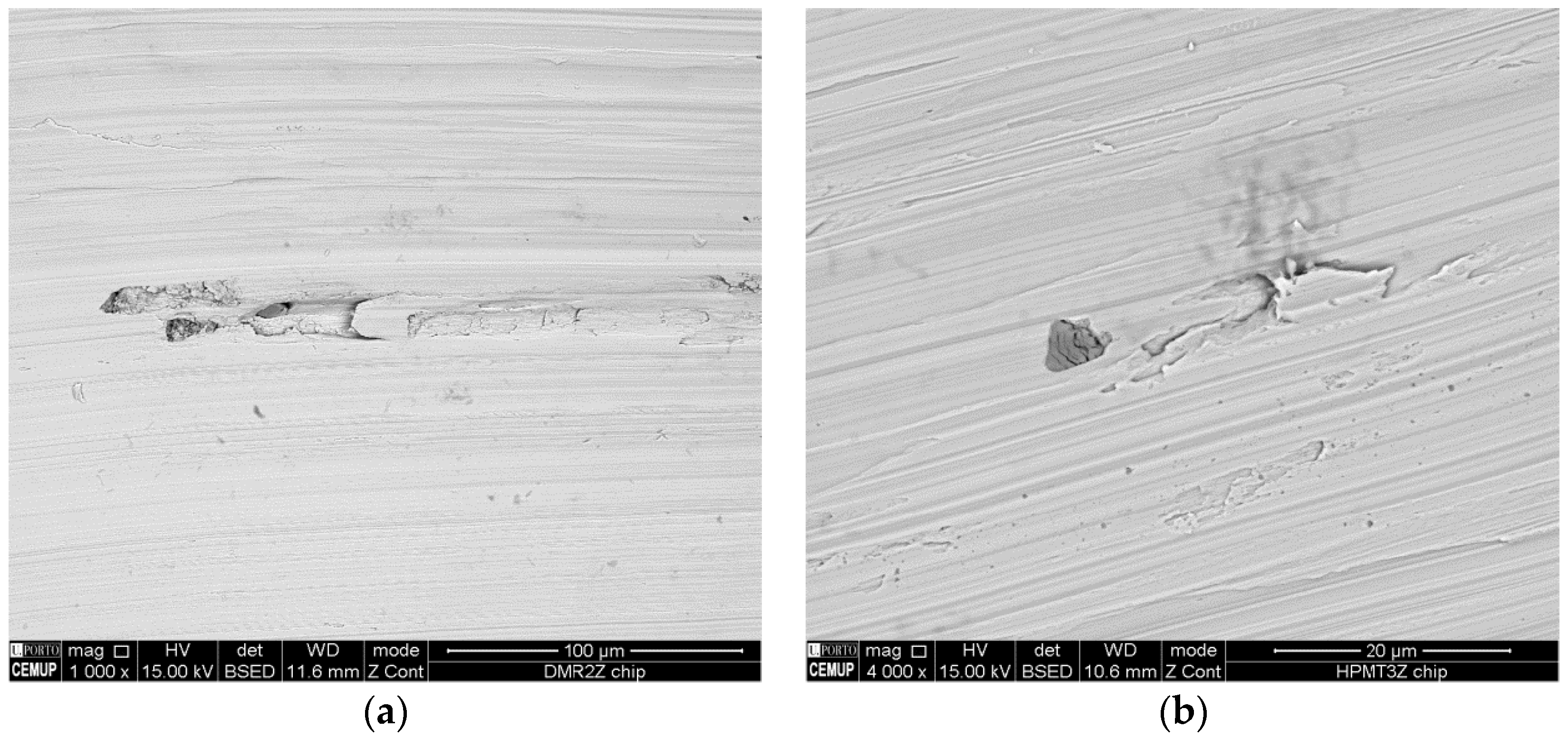
All tools used in the experimental trials demonstrated similar types of wear, having some suffered more wear than others. In a broad way, it is possible to say that the main issues encountered were flank wear, chipping, cracking and breakage of the cutting edges. These issues manifested in different levels of severity. Tools with higher wear demonstrated poorer machined surfaces, while tools that suffered breakage created surfaces with noticeable feed marks.
The depth of cut used for all trials (0.5 mm) was more in tune with a finishing operation rather than a conventional roughing operation. The small material removal rate, aided with cutting fluid, allows a reduction of temperatures at the tool’s tip. The use of cutting fluids gives way to a large variation of temperature during machining, creating heat cycles which may lead to thermal fatigue. This fatigue may perhaps be the cause of, for instance, cutting edge fractures or other encountered defects. When adding the inherent vibration (created by the machining of tough materials) to the equation, the potential for tool chipping and crack propagation is increased, which then leads to a higher tool failure probability.
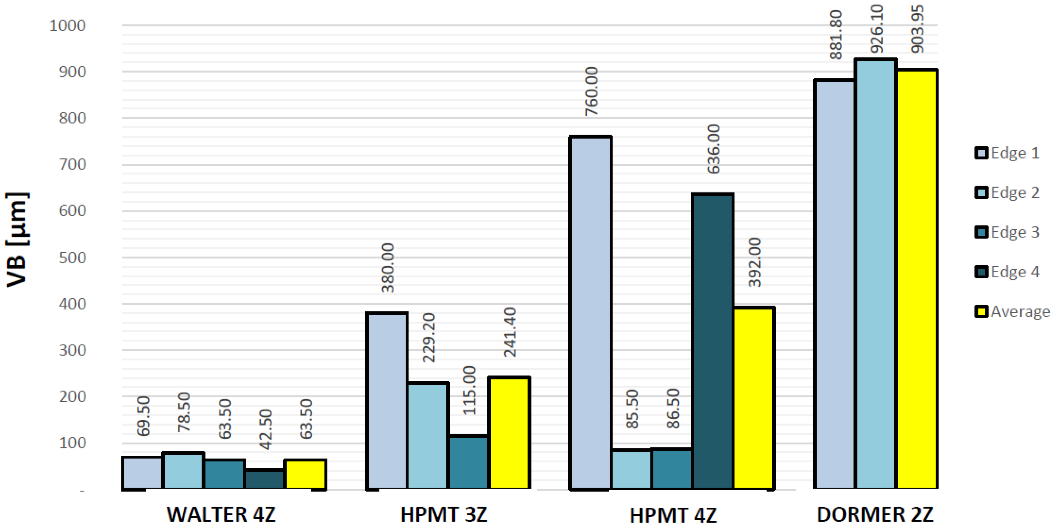
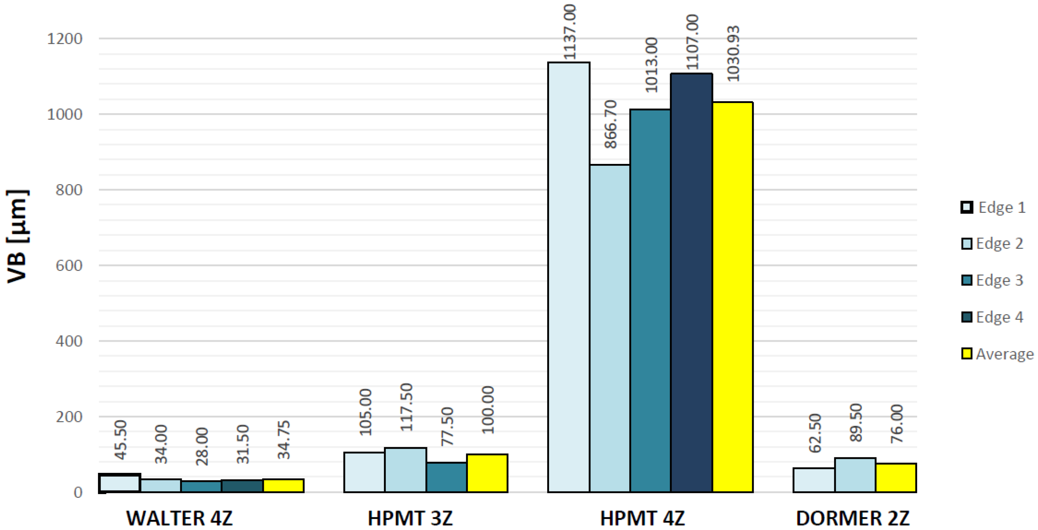
A comparison of flank wear suffered on each tool can be seen in Figure 12 and Figure 13. The WALTER 4Z TiAlN is the end mill with the lowest flank wear in the group having, as well, the smallest wear evolution when compared to the rest.
DORMER 2Z AlCrN came in second in terms of flank wear for the smaller cycle run, however, when compared to the results after 16 machining cycles, it is noticeable that this tool suffered severe cutting edge wear. As this tool only has two cutting flutes, it is at a disadvantage when compared to the others, demanding that each flute do extra work to achieve the same 15 m machining distance.
HPMT 3Z AlCrN achieved similar low VB values for the initial trial indicating low tool wear, and demonstrated the second best result after 16 cycles of machining. Although obtaining reasonable results, a large variation of flank wear between cutting flutes is present. Despite the fact that a low flank wear is present, this tool gave the highest surface roughness of all machined parts, delivering an inferior machined surface finish.
As stated previously, the HPMT 4Z AlCrN end mill suffered extended wear and damage during the first trial, exhibiting an overall significant degree of wear. SEM results for the lengthier trial show a large wear variation between cutting flutes. This variation may support the statement given previously which speculates that this tool dealt with different levels of hardness during its machining operation due to the presence of heterogeneities in the material.
Considering Figure 12, Figure 13, Figure 14 and Figure 15, it is possible to state that the WALTER 4Z TiAlN end mill:
  • Showed the overall best performance of the experiments;
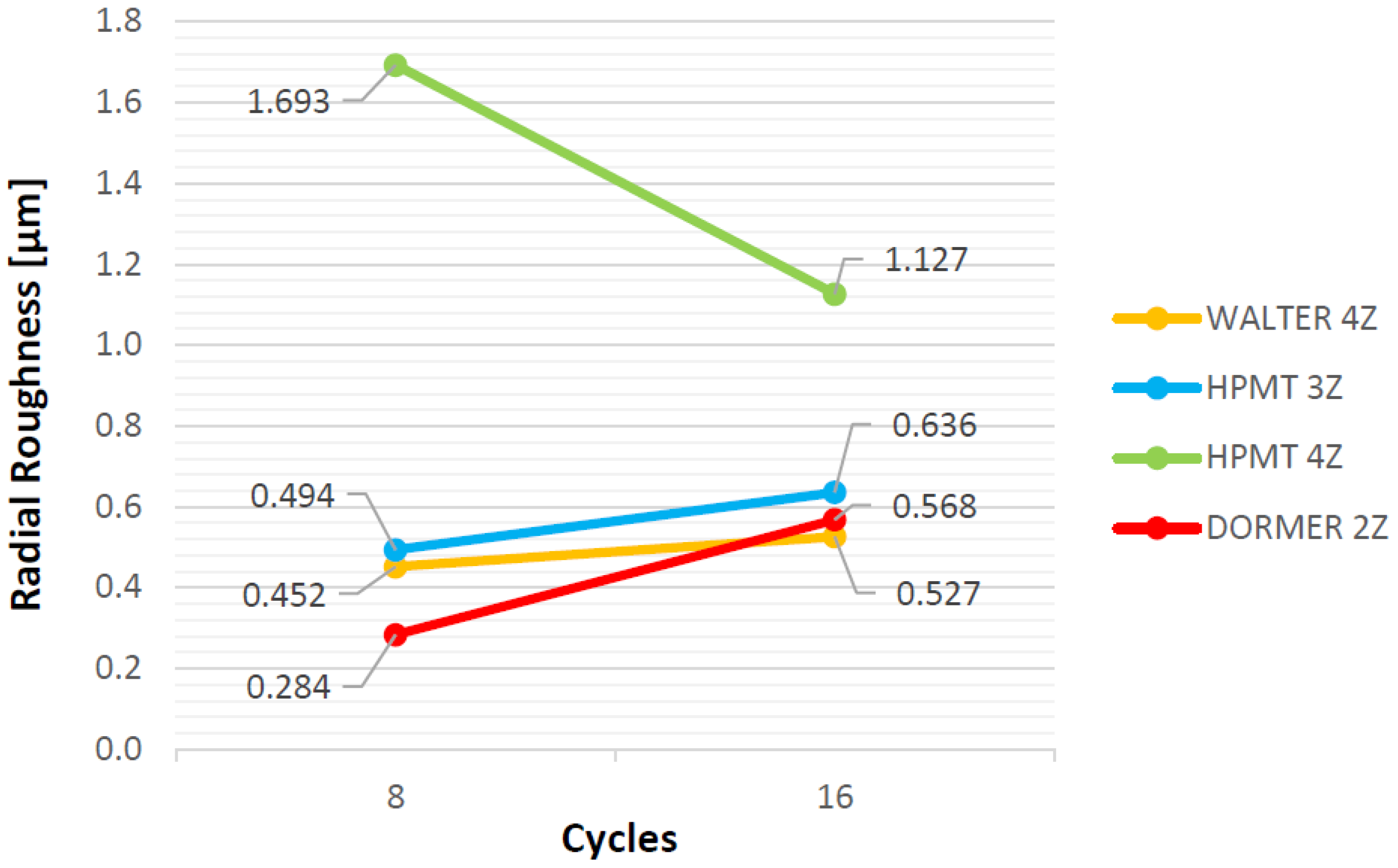
  • Gave the second best/lowest radial and tangential surface roughness results for the 8 cycles trial and the best/lowest for the 16 cycles trial;
  • The quality of the machined surface is maintained independently of the increase in machining distance/working life of the tool. This can be seen by the registered low VB values of the cutting flutes and by the small slope of the line that correlates surface roughness between the first and second trials. This slope is the smallest among all the tools indicating a slower wear evolution and consequently longer tool life.
As can be seen in the previous figures, the coatings are valid essentially during the initial stage of the trials. Posteriorly, it is possible to observe deeply worn cutting edges, displaying coating detachment and requiring the hard metal substrate to work without any of the advantages conferred by the coating. Thus, it is important to observe the wear evolution from the 8 cycles to 16 cycles trials. The TiAlN coating displays better results in terms of flank wear, both in 8 and 16 cycles trials. All the AlCrN coatings demonstrate premature detachment and severe wear, mainly after 16 machining cycles. Hence, it can be stated that, when machining Duplex Stainless Steel, a TiAlN coating displays better results in terms of machining work than a AlCrN coating.
Hard metal grade seems to play an important role in wear evolution as some tools showed substrate wear and corresponding degradation in terms of flank wear.
The number of flutes is also an important issue to consider because when using the same feed speed on a tool with less cutting flutes, the number of tool rotations and corresponding impact increase, leading to a premature cutting edge wear.
The overall best tool (WALTER 4Z TiAlN) has a coating composed by titanium aluminium nitride. This coating was shown to be generally superior in terms of longevity and quality of machined surfaces. The aluminium oxide promotes high temperature resistance while the combination of elements promotes a hard and tough surface. In fact, the general consensus is that tools that are properly coated improve longevity and optimize cutting parameters.

5. Conclusions

All in all, it is possible to state that end mills with four cutting flutes maintained a better surface roughness, presenting the lowest Ra, Rz and Rmax results for the 16 cycles trials. They are an appropriate choice to perform side milling operations on the grade of Duplex Stainless Steel used in this study. Nonetheless, the other tested end mills showed interesting results (only slightly worse than the four-flute end mills), being more suitable for slotting or down milling operations. In these types of machining operations, having lesser cutting flutes gives the advantage of easily and effectively extracting chips from the tooling edges. This ease of extraction avoids potential material adhesion or build up on cutting edges, phenomena that worsens when machining materials with similar compositions as the ones here tested. On the downside, tools with only two or three cutting flutes tend to have a shorter working life owing to the fact that, to machine the same distance, each cutting knife has a higher work load when compared, for example, to four-flute end mills. The work load per tooth is independent of speed parameters, such as the feed per tooth speed of the machining center.
The duplex stainless steel used in the experiments proved to be very harsh on the cutting tools. Even though the machining distance used in the trials is considered to be relatively short, the tested tools suffered extended damage and wear, exemplifying how difficult it is to work and process these types of materials.
It seems to have been made clear that WALTER 4Z TiAlN end mill delivered the best results in terms of wear and almost always of machined surface quality. Worth mentioning as well is that, in spite of suffering large wear, the surface quality of parts machined with DORMER 2Z AlCrN end mill revealed very good results, being close to those of the other tools. However, this outcome can be attributed essentially to the quality of the tool substrate, made from a very good hard metal grade.
Thus, despite the large evolution registered by AlCrN coatings, this work shows that TiAlN is yet more effective in cutting tough materials, such as Duplex Stainless Steel grades, in end mill machining operations.

Acknowledgments

Authors would like to thanks to António Pedro Pinho from ARSOPI, S.A., Vitor Almeida from DORMER TOOLS Portugal, Lda. and Fernando Reis from F. REIS, Lda., due to their support and collaboration in this work. The institutions ISEP—School of Engineering, Polytechnic of Porto and INEGI—Instituto de Ciência e Inovação em Engenharia Mecânica e Engenharia Industrial are also acknowledge due to permission to use their facilities and financial support.

Author Contributions

Pedro Reis and Francisco Silva conceived and designed the experiments; Pedro Reis performed the experiments; Pedro Reis, Francisco Silva and António Baptista analyzed the data; Ronny Gouveia and Francisco Silva wrote the paper.

Conflicts of Interest

The authors declare no conflict of interest.

References

  1. Munoz-Escalona, P.; Maropoulos, P.G. A geometrical model for surface roughness prediction when face milling Al 7075-T7351 with square insert tools. J. Manuf. Syst. 2015, 30, 216–223. [Google Scholar] [CrossRef]
  2. Cui, X.; Zhao, J.; Pei, Z. Analysis of transient average tool temperatures in face milling. Int. Commun. Heat Mass 2012, 39, 786–791. [Google Scholar] [CrossRef]
  3. Sato, M.; Ueda, T.; Tanaka, H. An experimental technique for the measurement of temperature on CBN tool face in end milling. Int. J. Mach. Tool. Manuf. 2007, 47, 2071–2076. [Google Scholar] [CrossRef]
  4. McFeron, D.E.; Chao, B.T. Transient interface temperatures in plain peripheral milling. J. Eng. Ind.-T. ASME 1956, 80, 321–329. [Google Scholar]
  5. Palmai, Z. Cutting temperature in intermittent cutting. Int. J. Mach. Tool. Manuf. 1987, 27, 261–274. [Google Scholar] [CrossRef]
  6. Martinho, R.P.; Silva, F.J.G.; Baptista, A.P.M. Cutting forces and wear analysis of Si3N4 diamond coated tools in high speed machining. Vacuum 2008, 82, 1415–1420. [Google Scholar] [CrossRef]
  7. Rawangwong, S.; Chatthong, J.; Boonchouytan, W.; Burapa, R. Influence of Cutting Parameters in Face Milling Semi-Solid AA 7075 Using Carbide Tool Affected the Surface Roughness and Tool Wear. Energy Procedia 2014, 56, 448–457. [Google Scholar] [CrossRef]
  8. Zhang, J.Z.; Chen, J.C.; Kirby, E.D. Surface roughness optimization in an end-milling operation using the Taguchi design method. J. Mater. Process. Technol. 2007, 184, 233–239. [Google Scholar] [CrossRef]
  9. Saï, W.B.; Salah, N.B.; Lebrun, J.L. Influence of machining by finishing milling on surface characteristics. Int. J. Mach. Tool. Manuf. 2001, 41, 443–450. [Google Scholar]
  10. Li, W.; Guo, Y.B.; Barkey, M.E.; Jordon, J.B. Effect Tool Wear during End Milling on the Surface Integrity and Fatigue Life of Inconel 718. Procedia CIRP 2014, 14, 546–551. [Google Scholar] [CrossRef]
  11. Stepan, G.; Munoa, J.; Insperger, T.; Surico, M.; Bachrathy, D.; Dombovari, Z. Cylindrical milling tools: Comparative real case study for process stability. CIRP Anal. Manuf. Technol. 2014, 63, 385–388. [Google Scholar] [CrossRef]
  12. Souza, A.F.; Machado, A.; Beckerta, S.F.; Diniz, A.E. Evaluating the roughness according to the tool path strategy when milling free form surfaces for mold application. Procedia CIRP 2014, 14, 188–193. [Google Scholar] [CrossRef]
  13. Silva, F.J.G.; Martinho, R.P.; Baptista, A.P.M. Characterization of laboratory and industrial CrN/CrCN/diamond-like carbon coatings. Thin Solid Films 2014, 550, 278–284. [Google Scholar] [CrossRef]
  14. Silva, F.J.G.; Martinho, R.P.; Alexandre, R.J.D.; Baptista, A.P.M. Increasing the wear resistance of molds for injection of glass fiber reinforced plastics. Wear 2011, 271, 2494–2499. [Google Scholar] [CrossRef]
  15. Denkena, B.; Kohler, J.; Bergmann, B. Development of cutting edge geometries for hard milling operations. CIRP J. Manuf. Sci. Technol. 2015, 8, 43–52. [Google Scholar] [CrossRef]
  16. Mayrhofer, P.H.; Mitterer, C.; Hultman, L.; Clemens, H. Microstructural design of hard coatings. Prog. Mater. Sci. 2006, 51, 1032–1114. [Google Scholar] [CrossRef]
  17. Cadena, N.L.; Cue-Sampedro, R.; Siller, H.R.; Arizmendi-Morquecho, A.M.; Rivera-Solorio, C.I.; Di-Nardo, S. Study of PVD AlCrN Coating for Reducing Carbide Cutting Tool Deterioration in the Machining of Titanium Alloys. Materials 2013, 6, 2143–2154. [Google Scholar] [CrossRef]
  18. Bohler Edelsthal (Austria), W705 Steel Datasheet, W705 DE 01.02 EM-WS. Available online: www.bohler.at/deutsch/files/downloads/W705.pdf (accessed on 4 July 2016).
  19. ISO 6892-1:2016 Metallic Materials—Tensile Testing—Part 1: Method of Test at Room Temperature; International Organization for Standardization: Geneva, Switzerland, 2016.
  20. ISO 6506-1:2014 Metallic Materials—Brinell Hardness Test—Part 1: Test Method; International Organization for Standardization: Geneva, Switzerland, 2014.
  21. DIN 6350-2:2010-05 Lathe Chucks, Hand-Operated—Centric clamp—Part 1: Cylindrical Mounting Recess; German Institute for Standardization: Berlin, Germany, 2010.
  22. DIN 69871-1-1995 AD/B—Tool Shanks with 7/24 Taper for Automatic Tool Exchange—Part 1: Type A, Type AD, Type B and with Data Media; German Institute for Standardization: Berlin, Germany, 1995.
  23. ISO 4288:1996 Geometrical Product Specifications (GPS)—Surface Texture: Profile Method—Rules and Procedures for the Assessment of Surface Texture; International Organization for Standardization: Geneva, Switzerland, 1996.
  24. Manual Técnico de Usinagem: Torneamento, Fresamento, Furaçãp, Mandrilamento e Sistemas de Fixação; AB Sandvik Coromant: Sandviken, Sweden, 2005; pp. A88–A89, (In Portuguese/Brasil).
Figure 1. (a) 3-jaw self-centering chuck attached to the work table securing the steel bar; (b) Hydraulic tool holder; (c) Complete assembly during a machining run.
Coatings 06 00051 g001
Figure 2. Tool path strategy.
Coatings 06 00051 g002
Figure 3. Chemical composition of encountered surface areas on Walter 4Z TiAlN mill after 16 cycles of machining. (a) Discontinuous areas and impurities detected on the tool (mag. 500×); (b) Close up of adhered foreign material (mag. 4000×); (c) Chemical composition of area marked as Z1; (d) Chemical composition of area marked as Z2; (e) Chemical composition of area marked as Z3.
Coatings 06 00051 g003aCoatings 06 00051 g003b
Figure 4. SEM analysis of cutting tool HPMT 3Z after 8 cycles. (a) Build up edge on flank (mag. 300×); (b) Build up edge on flank (mag. 750×) with marked area (Z1) for EDS analysis; (c) EDS analysis of marked area Z1.
Coatings 06 00051 g004aCoatings 06 00051 g004b
Figure 5. Heterogeneous inclusions found in post-trial machined material chip/shavings: (a) Global view of heterogeneous inclusion (mag. 1000×); (b) Close up of inclusion (mag. 4000×).
Coatings 06 00051 g005
Figure 6. SEM analysis for cutting tool HPMT 4Z after 16 cycles: (a) Marked areas of detected discontinuities (mag. 500×); (b) EDS analysis for marked area Z1; (c) EDS analysis of marked area Z2.
Coatings 06 00051 g006aCoatings 06 00051 g006b
Figure 7. Chip SEM analysis: (a) Chip made by HPMT 3Z AlCrN (mag. 50×); (b) Chip created by of HPMT 3Z AlCrN (mag. 160×); (c) Chip made by DORMER 2Z AlCrN (mag. 50×); (d) Chip created by DORMER 2Z AlCrN (mag. 220×).
Coatings 06 00051 g007
Figure 8. SEM analysis of chip made by HPMT 3Z AlCrN during an 8 cycles trial: (a) Overall view of chip (mag. 220×); (b) Close up detail of chips crushed surface (mag. 3750×).
Coatings 06 00051 g008
Figure 9. SEM analysis of chip made by DORMER 2Z AlCrN during an 8 cycles trial: (a) Overall view of chip (mag. 200×); (b) Close-up detail of chip crushed surface (mag. 3750×).
Coatings 06 00051 g009
Figure 10. Roughness values observed on machined surfaces after 8 cycles.
Coatings 06 00051 g010
Figure 11. Roughness values observed on machined surfaces after 16 cycles.
Coatings 06 00051 g011
Figure 12. Flank wear (VB) values registered on the edges of each end mill for 8 cycles.
Coatings 06 00051 g012
Figure 13. Flank wear (VB) values registered on the edges of each end mill for 16 cycles.
Coatings 06 00051 g013
Figure 14. Radial roughness evolution from eight to 16 cycles of machining.
Coatings 06 00051 g014
Figure 15. Tangential roughness evolution from eight to 16 cycles of machining.
Coatings 06 00051 g015
Table 1. Milling tools used in comparative study: End mill cutting tools (D = 4 mm).
BrandModelSubstrate MaterialCoatingZ 1
Walter Protostar N45 CompactH30140418-4Hard metalTiAlN 24
HPMT SE30 Plunge-MillG10040005006Hard metalAlCrN 33
HPMT SE45 Noviano StandardV47BXZ024GX040001Hard metalAlCrN 34
DORMER SpectrumS812HAHard metalAlCrN 32
Notes: 1 Number of cutting flutes; 2 Titanium aluminium nitride; 3 Aluminium chromium nitride.
Table 2. Machining parameters for each tool.
ToolZ 1N 2 (rpm)vc 3 (mm/min)vf 4 (mm/min)fz 5 (mm/tooth)ae 6 (mm)ap 7 (mm)
Walter 4Z TiAlN4400050.272500.015630.5
HPMT 3Z AlCrN3400050.271900.015830.5
HPMT 4Z AlCrN4400050.271800.0113 830.5
DORMER 2Z AlCrN2400050.271250.015630.5
Notes: 1 Number of cutting flutes; 2 Spindle speed; 3 Cutting speed; 4 Feed speed or tables speed; 5 Feed per tooth speed; 6 Working engagement; 7 Depth of cut; 8 fz value lower than expected due to geometrical conditions of tool (higher cutting area).
Table 3. Experimental parameters for each trial.
Cycles/Machining DistanceTrialToolCoatingZ 1N 2 (rpm)vc 3 (mm/min)vf 4 (mm/min)fz 5 (mm/tooth)ae 6 (mm)ap 7 (mm)
8/7.5 m1WALTER 4ZTiAlN4400050.272500.015630.5
2HPMT 3ZAlCrN3400050.271900.015830.5
3HPMT 4ZAlCrN4400050.271800.011330.5
4DORMER 2ZAlCrN2400050.271250.015630.5
16/15 m5WALTER 4ZTiAlN4400050.272500.015630.5
6HPMT 3ZAlCrN3400050.271900.015830.5
7HPMT 4ZAlCrN4400050.271800.011330.5
8DORMER 2ZAlCrN2400050.271250.015630.5
Notes: 1 Number of cutting flutes; 2 Spindle peed; 3 Cutting speed; 4 Feed speed or tables speed; 5 Feed per tooth speed; 6 Working engagement; 7 Depth of cut.
Table 4. Part surface roughness obtained after 8 and 16 cycles of machining with Walter 4Z TiAlN end mill.
Measurements Ra (µm)Rz (µm)Rmax (µm)
8 Cycles16 Cycles8 Cycles16 Cycles8 Cycles16 Cycles
Radial10.4430.5312.5623.5095.2206.460
20.4720.5452.6443.2625.4207.690
30.4420.5042.6872.7845.3906.670
Average0.4520.5272.6313.1855.3436.940
Tangential10.2590.2471.6811.5152.3601.740
20.2530.2611.5521.5742.0401.780
30.2680.2441.5681.5531.7601.720
Average0.2600.2511.6001.5472.0531.747
Table 5. Walter 4Z TiAlN SEM analysis after 8 cycles of machining.
Top View of End Mill
Coatings 06 00051 i001 Coatings 06 00051 i002
Observable Issues Analysis
Observed IssuesProbable CausesPossible Solutions
Edge chipping [24]
Coatings 06 00051 i003
  • Unstable machining conditions
  • Hard/fragile tool class
  • Stabilize machining conditions
  • Select tools with tougher geometry
Cutting Edges Close Up
Coatings 06 00051 i004 Coatings 06 00051 i005
Coatings 06 00051 i006 Coatings 06 00051 i007
Notes: (a) Secondary electron imaging (mag. 50×); (b) Retro diffused electron imaging (mag. 50×); (c) Cutting edge 1 with VB = 45.50 µm (mag. 500×); (d) Cutting edge 2 with VB = 34.00 µm (mag. 500×); (e) Cutting edge 3 with VB = 28.00 µm (mag. 500×); (f) Cutting edge 4 with VB = 31.50 µm (mag. 500×).
Table 6. Walter 4Z TiAlN SEM analysis after 16 cycles of machining.
Top View of End Mill
Coatings 06 00051 i008 Coatings 06 00051 i009
Observable Issues Analysis
Damage IssuesProbable CausesPossible Solutions
Notch Wear [24]
Coatings 06 00051 i010
  • Friction
  • Oxidation
  • Hardened or doughy material
  • Negative geometry
  • Increase rake angle to improve sharpness
  • Change depth of cut
  • CVD coating to improve wear
  • PVD coating to improve BUE and scaling of tool
Edge Chipping [24]
Coatings 06 00051 i011
  • Unstable machining conditions
  • Hard/fragile tool class
  • Stabilize machining conditions
  • Select tools with tougher geometry
Cutting Edges Close Up
Coatings 06 00051 i012 Coatings 06 00051 i013
Coatings 06 00051 i014 Coatings 06 00051 i015
Notes: (a) Secondary electron imaging (mag. 50×); (b) Retro diffused electron imaging (mag. 50×); (c) Cutting edge 1 with VB = 69.50 µm (mag. 500×); (d) Cutting edge 2 with VB = 78.50 µm (mag. 500×); (e) Cutting edge 3 with VB = 63.50 µm (mag. 500×); (f) Cutting edge 4 with VB = 42.50 µm (mag. 500×).
Table 7. Part surface roughness obtained after 8 and 16 cycles of machining with HPMT 3Z AlCrN end mill.
Measurements Ra (µm)Rz (µm)Rmax (µm)
8 Cycles16 Cycles8 Cycles 16 Cycles8 Cycles16 Cycles
Radial10.5260.6332.9603.1945.4005.050
20.4930.6122.7793.0774.4204.060
30.4630.6632.5563.4454.5705.160
Average0.4940.6362.7653.2394.9794.757
Tangentia10.2740.3861.9532.2802.5702.410
20.3130.3701.9142.2332.2902.500
30.3300.3502.1072.0992.3402.460
Average0.3060.3691.9912.2042.4002.457
Table 8. HPMT 3Z AlCrN SEM analysis after 8 cycles of machining.
Top View of End Mill
Coatings 06 00051 i016 Coatings 06 00051 i017
Observable Issues Analysis
IssuesProbable CausesPossible Solutions
Coatings 06 00051 i018
Edge chipping [24]
  • Unstable machining conditions
  • Hard/fragile tool class
  • Stabilize machining conditions
  • Select tools with tougher geometry
Flank wear [24]
Coatings 06 00051 i019
  • Excessive cutting speed
  • Low wear resistance/tool grade too soft
  • Feed rate too low
  • Flank angle too small
  • Lower cutting speed
  • Select tools with higher toughness grade
  • Increase feed rate
  • Increase flank angle
Cutting Edges Close Up
Coatings 06 00051 i020 Coatings 06 00051 i021
Coatings 06 00051 i022
Notes: (a) Secondary electron imaging (mag. 50×); (b) Retro diffused electron imaging (mag. 50×); (c) Cutting edge 1 with VB = 105.00 µm (mag. 300×); (d) Cutting edge 2 with VB = 117.50 µm (mag. 300×); (e) Cutting edge 3 with VB = 77.50 µm (mag. 300×).
Table 9. HPMT 3Z AlCrN SEM analysis after 16 cycles of machining.
Top View of End Mill
Coatings 06 00051 i023 Coatings 06 00051 i024
Observable Issues Analysis
Damage IssuesProbable CausesPossible Solutions
Notch wear [24]
Coatings 06 00051 i025
  • Friction
  • Oxidation
  • Hardened or doughy material
  • Negative geometry
  • Increase rake angle to improve sharpness
  • Change depth of cut
  • CVD coating to improve wear
  • PVD coating to improve BUE and scaling of tool
Edge Chipping [24]
Coatings 06 00051 i026
  • Unstable machining conditions
  • Hard/fragile tool class
  • Stabilize machining conditions
  • Select tools with tougher geometry
Flank wear [24]
Coatings 06 00051 i027
  • Excessive cutting speed
  • Low wear resistance/tool grade too soft
  • Feed rate too low
  • Flank angle too small
  • Lower cutting speed
  • Select tools with higher toughness grade
  • Increase feed rate
  • Increase flank angle
Cutting Edges Close Up
Coatings 06 00051 i028 Coatings 06 00051 i029
Coatings 06 00051 i030
Notes: (a) Top view of end mill by secondary electron imaging (mag. 50×); (b) Top view of end mill by retro diffused electron imaging (mag. 50×); (c) Cutting edge 1 with VB = 380.00 µm (mag. 300×); (d) Cutting edge 2 with VB = 229.20 µm (mag. 300×); (e) Cutting edge 3 with VB = 115.00 µm (mag. 300×).
Table 10. Part surface roughness obtained after 8 and 16 cycles of machining with HPMT 4Z AlCrN end mill.
Measurements Ra (µm)Rz (µm)Rmax (µm)
8 Cycles16 Cycles8 Cycles16 Cycles8 Cycles16 Cycles
Radial11.7711.1849.5906.52827.65015.010
21.5941.1179.4326.10523.53015.440
31.7141.07910.5136.39322.19014.860
Average1.6931.1279.8456.34224.45715.103
Tangential11.1910.2596.2621.8497.9502.500
21.2800.2556.6791.7587.0702.100
31.3600.2466.9171.6718.8701.960
Average1.2770.2536.6191.7597.9632.187
Table 11. HPMT 4Z AlCrN SEM analysis after 8 cycles of machining.
Top View of End Mill
Coatings 06 00051 i031 Coatings 06 00051 i032
Observable Issues Analysis
Damage IssuesProbable CausesPossible Solutions
Notch Wear [24]
Coatings 06 00051 i033
  • Friction
  • Oxidation
  • Hardened or doughy material
  • Negative geometry
  • Increase rake angle to improve sharpness
  • Change depth of cut
  • CVD coating to improve wear
  • PVD coating to improve BUE and scaling of tool
Edge Chipping [24]
Coatings 06 00051 i034
  • Unstable machining conditions
  • Hard/fragile tool class
  • Stabilize machining conditions
  • Select tools with tougher geometry
Breakage/Fracture [24]
Coatings 06 00051 i035
  • Excessive wear
  • Tool grade too hard
  • Lack of cutting edge strength
  • Lack of holder rigidity
  • Reduce vibrations
  • Lower feed rate
  • Tool grade with higher toughness
Cutting Edges Close Up
Cutting edge 1; VB = 1137 mm
Coatings 06 00051 i036
Cutting edge 2; VB = 866.7 µm
Coatings 06 00051 i037
Cutting edge 3; VB = 1013 mm
Coatings 06 00051 i038
Cutting edge 4; VB = 1107 mm
Coatings 06 00051 i039
Notes: (a) Top view of end mill by secondary electron imaging (mag. 50×); (b) Top view of end mill by retro diffused electron imaging (mag. 50×); (c) Cutting edge 1 with VB = 1137 mm (mag. 150×); (d) Cutting edge 2 with VB = 866.70 µm (mag. 150×); (e) Cutting edge 3 with VB = 1013 mm (mag. 150×); (f) cutting edge 4 with VB = 1107 mm (mag. 150×).
Table 12. HPMT 4Z AlCrN SEM analysis after 16 cycles of machining.
Top View of End Mill
Coatings 06 00051 i040 Coatings 06 00051 i041
Observable Issues Analysis
Damage IssuesProbable CausesPossible Solutions
Notch wear [24]
Coatings 06 00051 i042
  • Friction
  • Oxidation
  • Hardened or doughy material
  • Negative geometry
  • Increase rake angle to improve sharpness
  • Change depth of cut
  • CVD coating to improve wear
  • PVD coating to improve BUE and scaling of tool
Edge chipping [24]
Coatings 06 00051 i043
  • Unstable machining conditions
  • Hard/fragile tool class
  • Stabilize machining conditions
  • Select tools with tougher geometry
Breakage/Fracture [24]
Coatings 06 00051 i044
  • Excessive wear
  • Tool grade too hard
  • Lack of cutting edge strength
  • Lack of holder rigidity
  • Reduce vibrations
  • Lower feed rate
  • Tool grade with higher toughness
Cutting Edges Close Up
Coatings 06 00051 i045 Coatings 06 00051 i046
Coatings 06 00051 i047 Coatings 06 00051 i048
Notes: (a) Top view of end mill by secondary electron imaging (mag. 52×); (b) Top view of end mill by retro diffused electron imaging (mag. 52×); (c) Cutting edge 1 with VB = 760.00 µm (mag. 250×); (d) Cutting edge 2 with VB = 85.50 µm (mag. 500×); (e) Cutting edge 3 with VB = 86.50 µm (mag. 500×); (f) Cutting edge 4 with VB = 636.00 µm (mag. 250×).
Table 13. Part surface roughness obtained after 8 and 16 cycles of machining with DORMER 2Z AlCrN end mill.
Measurements Ra (µm)Rz (µm)Rmax (µm)
8 Cycles16 Cycles8 Cycles16 Cycles8 Cycles16 Cycles
Radial10.3150.5721.8183.4492.3606.470
20.2480.5531.5744.1922.2306.240
30.2890.5791.9613.4003.2006.640
Average0.2840.5681.7843.6802.5976.450
Tangential10.1880.3301.2552.1101.6102.320
20.1670.3521.0762.3111.2702.590
30.1850.3631.3292.1331.6003.180
Average0.1800.3481.2202.1851.4932.697
Table 14. DORMER 2Z AlCrN SEM analysis after 8 cycles of machining.
Top View of End Mill
Coatings 06 00051 i049 Coatings 06 00051 i050
Observable Issues Analysis
Damage IssuesProbable CausesPossible Solutions
Flank wear [24]
Coatings 06 00051 i051
  • Excessive cutting speed
  • Low wear resistance/tool grade too soft
  • Feed rate too low
  • Flank angle too small
  • Lower cutting speed
  • Select tools with higher toughness grade
  • Increase feed rate
  • Increase flank angle
Edge Chipping [24]
Coatings 06 00051 i052
  • Unstable machining conditions
  • Hard/fragile tool class
  • Stabilize machining conditions
  • Select tools with tougher geometry
Cutting Edges Close Up
Coatings 06 00051 i053 Coatings 06 00051 i054
Notes: (a) Top view of end mill by secondary electron imaging (mag. 50×); (b) Top view of end mill by retro diffused electron imaging (mag. 50×); (c) Cutting edge 1 with VB = 62.50 µm (mag. 500×); (d) Cutting edge 2 with VB = 89.50 µm (mag. 500×).
Table 15. DORMER 2Z AlCrN SEM analysis after 16 cycles of machining.
Top View of End Mill
Coatings 06 00051 i055 Coatings 06 00051 i056
Observable Issues Analysis
Damage IssuesProbable CausesPossible Solutions
Flank wear [24]
Coatings 06 00051 i057
  • Excessive cutting speed
  • Low wear resistance/tool grade too soft
  • Feed rate too low
  • Flank angle too small
  • Lower cutting speed
  • Select tools with higher toughness grade
  • Increase feed rate
  • Increase flank angle
Notch wear [24]
Coatings 06 00051 i058
  • Friction
  • Oxidation
  • Hardened or doughy material
  • Negative geometry
  • Increase rake angle to improve sharpness
  • Change depth of cut
  • CVD coating to improve wear
  • PVD coating to improve BUE and flaking of tool
Edge chipping [24]
Coatings 06 00051 i059
  • Unstable machining conditions
  • Hard/fragile tool class
  • Stabilize machining conditions
  • Select tools with tougher geometry
Breakage/Fracture [24]
Coatings 06 00051 i060
  • Excessive wear
  • Tool grade too hard
  • Lack of cutting edge strength
  • Lack of holder rigidity
  • Reduce vibrations
  • Lower feed rate
  • Tool grade with higher toughness
Cutting Edges Close Up
Cutting edge 1; VB = 881.8 µm
Coatings 06 00051 i061
Cutting edge 2; VB = 926.1 µm
Coatings 06 00051 i062
Notes: (a) Top view of end mill by secondary electron imaging (mag. 50×); (b) Top view of end mill by retro diffused electron imaging (mag. 50×); (c) Cutting edge 1 with VB = 881.80 µm (mag. 220×); (d) Cutting edge 2 with VB = 926.10 µm (mag. 220×).

