
Effect of Hydrogen Concentration on the Growth of Carbon Nanotube Arrays for Gecko-Inspired Adhesive Applications


Institute of Bio-inspired Structure and Surface Engineering, College of Astronautics, Nanjing University of Aeronautics and Astronautics, Nanjing 210016, China
*
Author to whom correspondence should be addressed.
Coatings 2017, 7(12), 221; https://doi.org/10.3390/coatings7120221
Submission received: 18 October 2017
/
Revised: 25 November 2017
/
Accepted: 2 December 2017
/
Published: 5 December 2017
Abstract
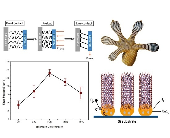
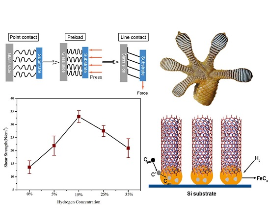
:Vertically-aligned carbon nanotubes (VACNTs) have extraordinary structural and mechanical properties, and have been considered as potential candidates for creating dry adhesives inspired by adhesive structures in nature. Catalytic chemical vapor deposition is widely used to grow VACNTs; however, the influential mechanism of VACNT preparation parameters (such as H2 concentration) on its adhesion property is not clear, making accurate control over the structure of VACNTs adhesive an ongoing challenge. In this article, we use electron beam-deposited SiO2/Al2O3 as a support layer, Fe as catalyst, and C2H4/H2 gas mixtures as a feed gas to prepare VACNTs, while varying the ratio of the reducing atmosphere (H2) from 0% to 35%. VACNTs synthesized at a 15% H2 concentration (5 mm × 5 mm in size) can support a maximal weight of 856 g, which indicates a macroscopic shear adhesive strength of 34 N/cm2. We propose a hydrogen-concentration-dependent model for the shear adhesive performance of VACNTs. By adjusting the amount of hydrogen present during the reaction, the morphology and quality of the prepared VACNTs can be precisely controlled, which significantly influences its shear adhesive performance. These results are advantageous for the application of carbon nanotubes as dry adhesives.
1. Introduction
Geckos contain millions of microscopic beta keratin hairs on their feet, which allow them to exhibit controllable adhesion and detachment of their feet from a surface. The ends of these hairs are split into nanoscale spatula-like structures, which come in close contact with the target surface to induce accumulated van der Waals forces (~10 N/cm2) and form strong bonds [1,2]. This unique adhesive capability of geckos has led to the development of advanced adhesives, including dry adhesives, which unlike chemical adhesives, leave no residue [3]. Such dry adhesives generally have micro-nano array structures, and are expected to be suitable for robotic end-effectors [4,5,6,7]. At present, there are generally two main types of materials being researched as materials for gecko-inspired dry adhesives [8]: Synthetic polymers [5,9,10] and vertically-aligned carbon nanotubes (VACNTs) [11,12,13,14]. Among them, the nano-scale diameters of carbon nanotubes are far less than the micro-scale diameters of the generally polymeric fibers. Zhao et al. [15] tested the adhesion strength of VACNTs with 5–10 μm height. Under 125 N/cm2 preload, the normal adhesion reached 11.7 N/cm2. Under 31.25 N/cm2, the shear adhesion reached 7.8 N/cm2. Ge et al. [16] designed VACNTs with pillar pattern structure, the shear adhesion of which reached 36 N/cm2, and sustained for 8–12 h. Through LPCVD (low-pressure chemical vapor deposition) method, Qu et al. [11] produced VACNTs with hierarchical structure, which could exert 100 N/cm2 shear adhesion and 10 N/cm2 normal adhesion, respectively. By synergy with straight bodies but curly entangled tops of VACNTs, better adaptability to the characteristics of contact glass surface is exhibited, resulting in greater and anisotropic adhesion [11]. This anisotropic adhesive behavior is also the key for geckos to switch between adhesion and detachment while moving [17]. During shear movement, the contact area of VACNT with target surface could be side contact, which is obviously larger than point contact during normal movement [18]. From the past research results, it is easy to conclude that the shear adhesive performance of VACNT is usually stronger than normal adhesive performance, exhibiting strong adhesion and easy detachment [19,20,21].
Given the extraordinary performance of carbon nanotubes in fabricating gecko-inspired dry adhesives, it is important to realize accurate control over the morphology and structure of the carbon nanotubes. Presently, catalytic chemical vapor deposition (CVD) is the main preparation method for obtaining carbon nanotubes due to its many advantages such as simple processing, low technical cost, and high degrees of control and scalability [22,23]. The mechanism of CNT growth through CVD methods has been studied [24,25,26,27,28,29]. The morphology and quality of the resulting CNTs depend on the catalyst, carbon source, temperature, flow rate, and feedstock pressure during CVD, among other factors [30]. Schneider [31] considered that the CVD growth process of VACNTs could be a complex situation, in which all of the parameters have to be precisely-tuned, individually against each other (such as processing parameters, size of the reactor, dwell time and sample positioning in the reactor) to obtain a CNT material with certain structure in the most reproducible way. During CVD, the mixture gas typically includes a carbon source, a reducing gas, and an inert carrier gas, which is then fed into an airtight tube furnace. Carbon deposition occurs by catalytic decomposition of the carbon source gas on the surface of metal nanoparticles under high temperature. Research on the effect of carbon source gas in the reaction atmosphere on CNT growth has been widely published previously [32,33,34]. It is generally accepted that the type and flow rate of the carbon source will affect the number of carbon atoms provided for CNT formation, and the accumulation of impurities (such as amorphous carbon) due to the self-decomposition of the carbon source is one of the reasons for the termination of CNT growth [35]. Studies regarding the influence of the reducing gas (usually hydrogen) in growth kinetics are relatively rare, although its effect on nanotube morphology has been investigated extensively [31,36]. One widely accepted theory is that hydrogen can remove the barriers for CNT growth by etching the impurities on the catalyst surface [37,38,39]. In addition, maintaining a balance between carbon and hydrogen radicals in the reaction system is very important for CNT growth [40]. Insufficient hydrogen causes the oxidized catalyst Fe to be reduced incompletely, while excessive hydrogen converted the carbon production in the gas phase into the reagents, thus decreasing the overall driving force of the process [41]. Joshi et al. [37,42,43] experimentally observed the role of water and hydrogen in terms of their influence on CNT growth, and point out that hydrogen controls the cracking of the carbon precursor ethylene, thereby controlling the purity as well as the number of walls of the CNTs grown. Schaber et al. [44,45] investigated the tribological properties of densely-packed VACNTs and the morphology effect on the frictional coefficients. Chen et al. [46] systematically tested the effect of packing density and surface roughness of VACNTs on their biomimetic frictional adhesion. Previous research into this phenomenon has focused on the influence of hydrogen on the morphology, size, distribution, and structure of the catalyst, or focused on the effect of morphology and structure on the adhesion property of VACNTs. Due to the multiple influencing factors of the CVD process, the influential mechanism of CNTs morphology and structure controlled by CVD processing parameters on their adhesion property is still not completely clear.
In this work, highly-controlled CVD growth was used to fabricate VACNTs. The morphology and structure of the prepared VACNTs were controlled by adjusting the amount of hydrogen in the reaction atmosphere. As mentioned above, the shear adhesive performance is usually stronger than normal pull-off force, thus the shear adhesive performances of these VACNTs prepared under different growth conditions were tested and compared using a hanging-weight system. Morphological and structural characterizations of the VACNTs were carried out to determine the mechanism by which hydrogen concentration during synthesis affects the shear adhesive performance of the final VACNTs.
2. Materials and Methods
2.1. VACNTs Preparation
A 4-inch silicon wafer was chosen as the growth substrate. A SiO2/Al2O3 (film thickness is 300 nm/20 nm) layer and a 2 nm-thick Fe film were deposited as support and catalyst, respectively, using an electron beam system (E-beam 500, Xingnan, Chengdu, China). Laser-cut growth substrates (5 mm × 5 mm in size) were placed into a CVD tube furnace (Nano-Tytan 160, Tystar Corporation, Garden Grove, CA, USA) and heated under Ar to a growth temperature of 750 °C. H2 concentration of 15% was injected into the furnace under low pressures (~100 Torr) for pretreatment of the catalyst; pretreatment reduces the oxide on the catalyst surface and etches the catalyst film into nano-scale metal islands. After 30 s of pretreatment, the carbon source gas ethylene (C2H4) was added to initiate CNT growth. While maintaining a constant flow of C2H4 (272 sccm) and the mixture atmosphere (1183 sccm), the proportion of hydrogen was adjusted to 0%, 5%, 15%, 25%, and 35% during different trials. After 40 min of deposition, VACNTs with different adhesive performance were obtained.
2.2. Characterization and Test Methods
High-resolution field emission scanning electron microscopy (HR-FESEM, S-4800, Hitachi, Japan) was used to analyze the morphology of the VACNTs prepared under different H2 conditions, including growth height, distribution density, and vertical orientation degree of the tube bodies. Field emission transmission electron microscopy (FETEM, Tecnai G2 F20, Thermo Fisher Scientific, Hilsporo, OR, USA) was used to further observe the diameter, wall number, and impurity distribution of single tubes. Laser confocal Raman spectroscopy (Raman, Labram HR 800, Horiba Scientific, Edison, NJ, USA) was used to analyze the defects and graphitization degree of VACNT samples in order to judge their quality and purity. The adhesive performance of the VACNTs was tested using a self-made hanging-weight system. In order to keep the preload constant each test, VACNT sample was first attached to a plastic sheet using double-sided adhesive tape and the top side of VACNTs made parallel contact with a glass slide. Another glass slide was covered on the back side of the plastic sheet to make a sandwich structure. The sandwich structure was placed on top of an electronic balance, the glass slide was hand-pressed until the display showed 1000 g (near 40 N/cm2). Then, glass slide B was taken and the hanging weight test was continued. In this way, the preload could be controlled precisely to some extent. Copper powder (Analytical Reagent, AR) was continuously added to the tray on the end of the plastic sheet to directly test the macroscopic shear adhesive strength of the VACNTs. The average was calculated as the shear adhesive strength of the VACNTs with three replications. The underlying causes of the different adhesive performances for VACNTs prepared under different hydrogen concentration conditions were analyzed. Atomic force microscopy (A Dimension 3100 AFM, Bruker-Nano, Santa Barbara, CA, USA) was used to analyze the morphology of catalyst surface after the CVD process under different H2 concentrations. After the CVD synthesis process, the carbon nanotube array was peeled off from the growth substrate with tweezers for the AFM test.
3. Results and Discussion
3.1. Morphological Analysis of VACNTs
The surface morphology of VACNTs is very important for their application as dry adhesive materials. SEM images of VACNTs prepared under different hydrogen conditions are presented in Figure 1, and show typical side profiles and top surfaces of VACNTs. Figure 1 illustrates the significant influence of hydrogen concentration on the morphology of prepared VACNTs. The absence of hydrogen during deposition causes CNTs to grow in a disorderly distribution and without coherent directional alignment. As shown in Figure 1a–c, the tube bodies of the CNTs gradually orient more in the vertical direction as more H2 is introduced into the reaction atmosphere. Figure 1c shows the sample under a H2 concentration of 15%, which presents relatively good vertically-aligned distribution among others. As the H2 concentration is further increased (Figure 1d,e), the neighboring tubes are entangled with each other and the vertical orientation of the tubes becomes random. From top-view SEM images, we also see that carbon nanotubes on the top surface of VACNTs prepared under a H2 concentration of 15% form uniform small clusters, which are beneficial to maximizing the contact area with the target surfaces to realize better adhesive performance [11].
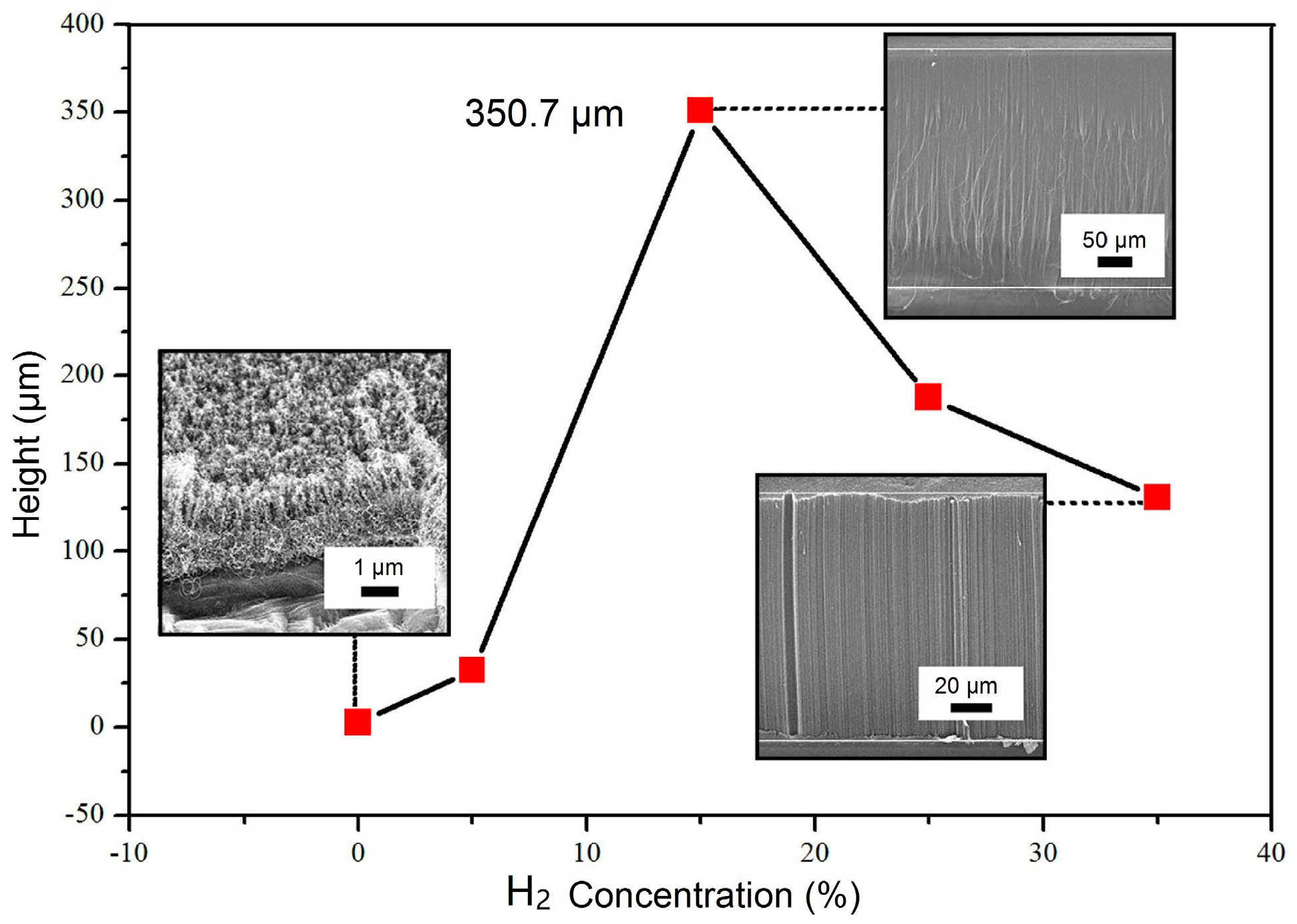
The height variation of VACNTs under different H2 concentrations are shown in Figure 2. There is almost no growth of VACNTs without hydrogen present during the deposition process. It can be speculated that without the etching effect of hydrogen, the amorphous carbon accumulates on the surface of the catalyst and hinders the contact between carbon atoms (from thermal decomposition of C2H4) and metal catalytic particles, thus seriously affecting the growth height of VACNTs [38]. When the H2 concentration increased to 15%, the prepared VACNTs reached a maximum height of 350.7 μm, which indicates that a suitable H2 concentration can make the growth of VACNTs more efficient. When the H2 concentration is gradually increased to 35%, there is an evident decrease in the growth height of the VACNTs. It can be explained that excess hydrogen reacts with the carbon product during deposition, hindering the effective growth of CNTs [41]. These results show that VACNTs synthesized under a H2 concentration of 15% feature a good vertical orientation, and the tops of these arrays form small and homogeneous clusters. The prepared VACNTs can grow up to 350.7 μm, which is high enough to adapt to the roughness of different surfaces. The hydrogen in this case can etch away the impurities on the catalyst surface, but does not react with the carbon product and affect the CNT growth efficiency.
Figure 3 shows TEM images of single CNTs prepared under H2 concentrations of 5%, 15%, 25%, and 35%, respectively. The height of VACNTs prepared under 0% H2 is too low to serve as interfacial adhesion material. When the H2 concentration was increased from 5% to 35%, the diameters of the prepared VACNTs were only slightly reduced, to approximately 10 nm. The number of walls in the multi-walled VACNTs prepared under H2 concentrations of 5%, 15%, 25%, and 35% are 9, 7, 6, and 4, respectively. The numbers of walls gradually decreased with increasing hydrogen concentration in the reaction atmosphere. It is widely accepted that catalyst particle size has a direct templating effect on the morphology and distribution of prepared CNTs [43,47,48,49,50,51]. We speculate that the change of hydrogen concentration in the gas deposition process (by influencing the catalyst particle size) leads to changes in the diameter and number of walls in the prepared VACNTs. It can be deduced from the variation of diameter that the catalyst particle size decreases slightly with increasing hydrogen concentration. The impurity distribution in the prepared VACNTs is also shown in Figure 3. The VACNTs prepared under a H2 concentration of 15% show a clean tube center, with few impurities or defects; only the outer walls of the tubes have a small number of impurities. This condition is therefore ideal for obtaining more orderly arranged CNTs and reducing the formation of amorphous carbon and other impurities.
3.2. The Quality Analysis of VACNTs
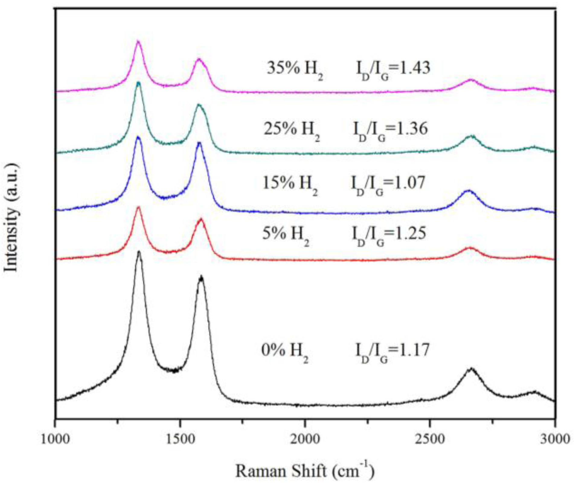
Raman spectroscopies of the different VACNTs are shown in Figure 4. There are two Raman characteristic peaks for CNTs. The D-band (~1350 cm−1) represents the structural defects and adsorbed carbon nanoparticles, amorphous carbon, and other nanoscale microcrystals on the tube walls. The G-band (~1580 cm−1) arises the E2g vibration of the graphite plane, characterizing the orderly graphitization of the tubes [52]. The D/G peak intensity ratios (ID/IG) of the VACNTs under H2 concentrations of 0% and 15% decreased from 1.17 to 1.07. This shows that the hydrogen added during the deposition process effectively etches these impurities and maintains a dynamic balance of carbon and hydrogen free radicals, favors the formation of sp2-like graphite structures, and ensures higher-quality VACNTs. As the hydrogen concentration continues to increase, the D/G peak intensity ratio increases as well. This indicates that additional hydrogen destroys the dynamic balance of carbon and hydrogen free radicals, forming sp3 structural defects on the walls of CNTs. Additionally, the formation of amorphous carbon and other impurities on the surface of arrays decreases the quality of VACNTs. A 15% H2 concentration is most favorable for growing VACNTs with a high degree of graphitization or crystallization, fewer defects and impurities, and higher quality.
3.3. Influence Mechanism of Hydrogen Concentration on VACNTs Synthesis
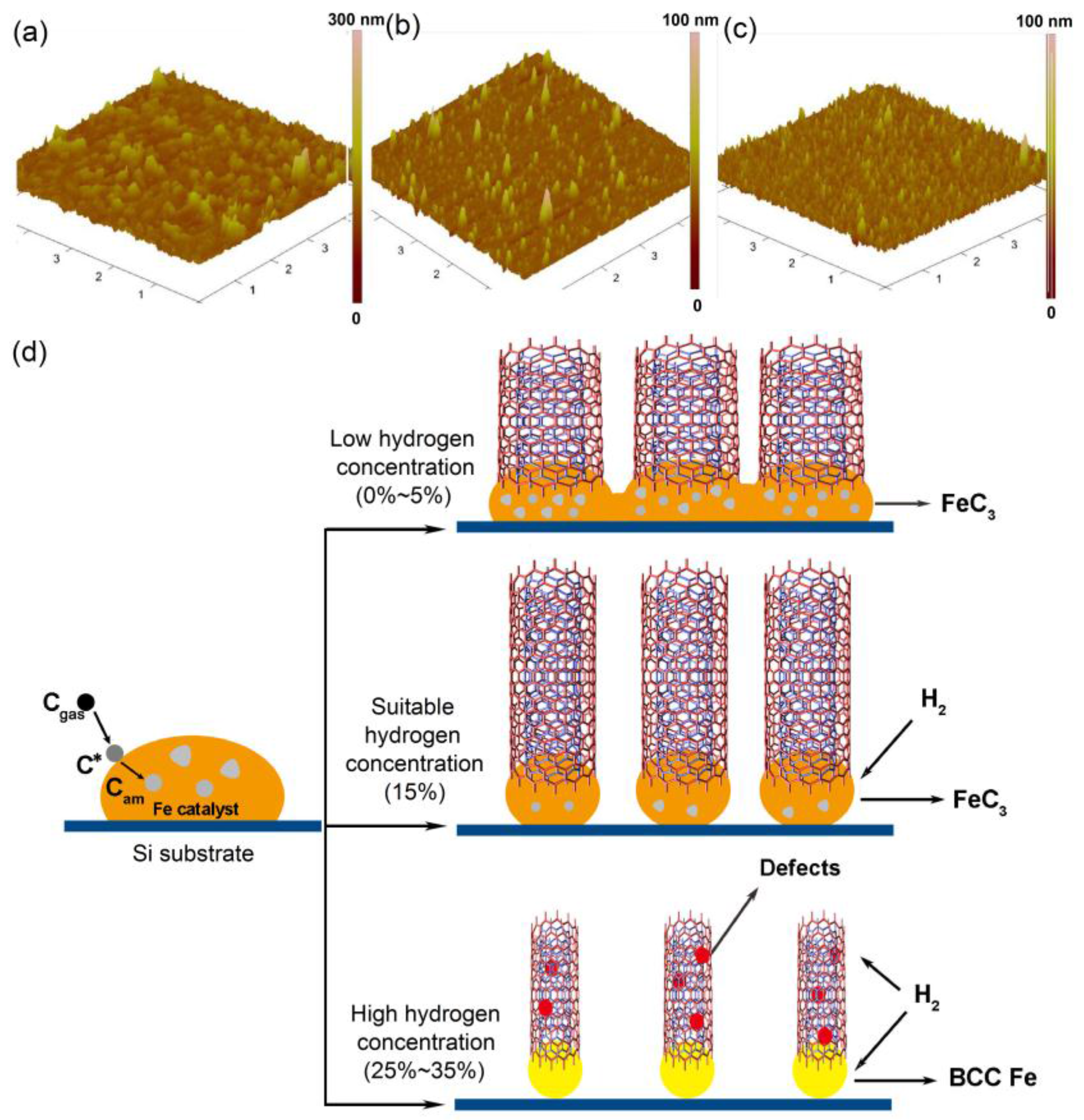
Based on the above observation and analysis, we examined the morphology of iron catalyst particles after CVD process under different H2 concentrations (as shown in Figure 5a–c), and propose a simple model to explain the influence of hydrogen concentration on the structure of VACNTs to explain the shear adhesive performance difference (as shown in Figure 5d). The growth process of CNTs includes two stages. First, the gas-phase precursor Cgas is shifted to an activated surface-bound form, C*. C* can then diffuse through the catalyst particles, and some of these C* species are incorporated into the growing carbon nanotubes. The remaining C* forms amorphous carbon patches Cam and other impurities that block the catalyst particle surface [53]. From Figure 5a, under the H2 concentrations of 5%, the size of iron catalyst is relatively larger and non-uniformly distributed, and some catalyst particles even aggregated. At low hydrogen concentrations (0%–5%), the small amount of hydrogen present cannot etch the catalyst layer to form evenly-distributed iron particles, which decreases the catalytic efficiency for the growth of VACNTs. The accumulated impurities on the catalyst surfaces hinder the carbon atoms from the thermal decomposition to effectively contact with the catalyst particles; thus, the growth height of the prepared VACNTs is significantly affected. The heights of the prepared VACNTs are sensitive to the characteristics of the contact surfaces, and then affect the adhesive properties. From Figure 5b, under the H2 concentration of 35%, the number of catalyst particles is relatively small and the size distribution is obviously uneven. At high hydrogen concentrations (25%–35%), the additional hydrogen can etch away the carbon impurities on the catalyst surface. However, there still exist more impurities and structure defects on the top surfaces and tube walls of VACNTs. Moreover, research of Behr et al. shows that the excess hydrogen changes the crystal phase of catalyst from FeC3 with catalyst activity into body-centered cubic (BCC) Fe [54]. So, we speculate that the excess hydrogen leads the saturated carbon atoms to form more sp3 structure defects but not sp2 graphite-structure arrangement by shifting the catalyst phase.
At the most suitable hydrogen concentration of 15%, it effectively etches the catalyst to form evenly-distributed iron particles (as shown in Figure 5c), which maximizes their catalytic efficiency and reduces the formation of impurities. The catalyst phase is maintained as the active component of FeC3, which ensures the most carbon atoms to separate out with sp2 graphite structure and grow VACNTs at a rapid rate. Therefore, the prepared samples can grow higher (up to 350 μm in our experiment), and have less structure defects and attached impurities.
3.4. Adhesive Performance Test of VACNTs
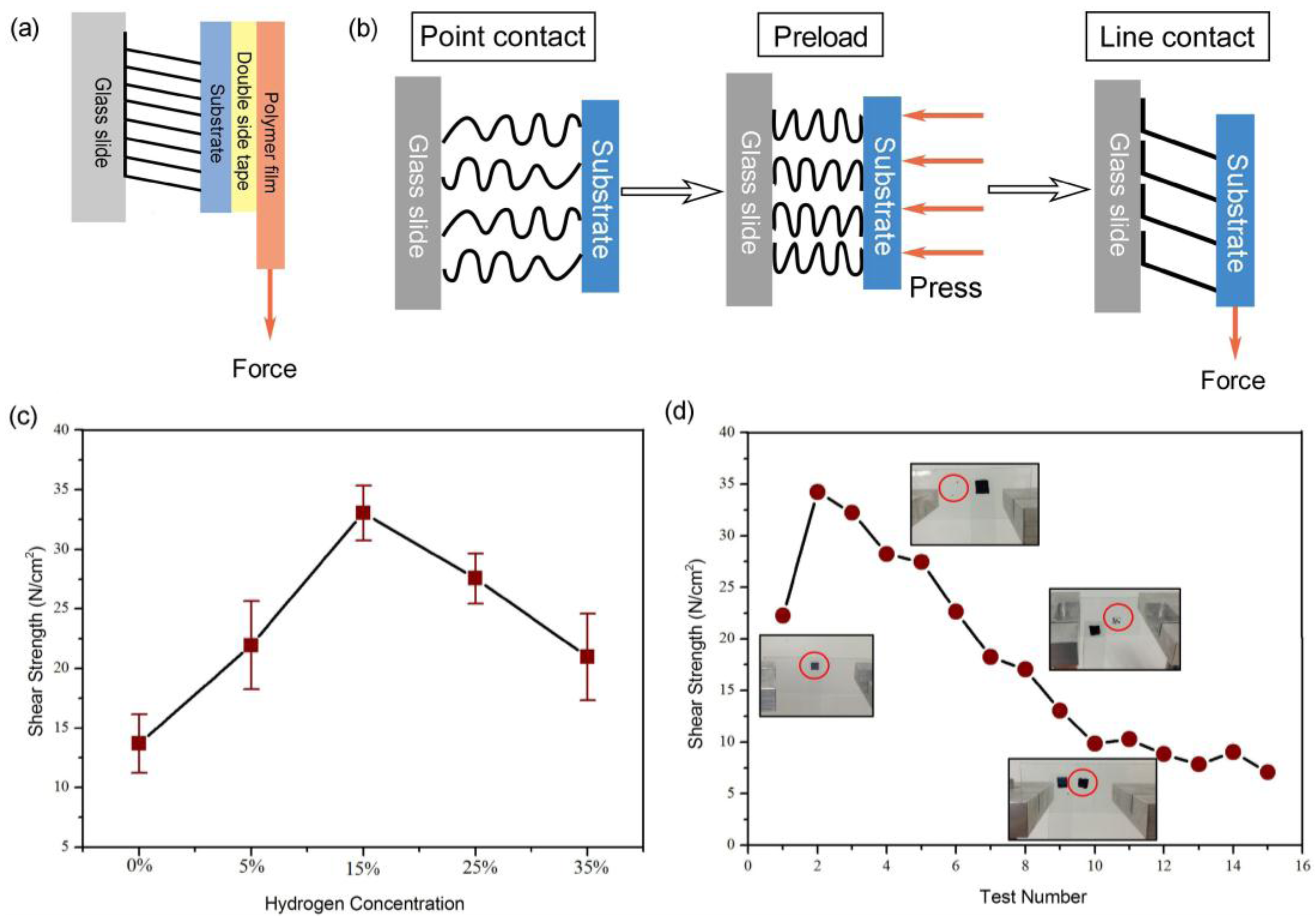
A hanging-weight system was used to test the macroscopic shear adhesive strength of the prepared VACNTs (Figure 6a). The institutive test method has been widely used to test the adhesion performance of VACNTs in previous research [11,13,14,15,19]. Samples 5 mm × 5 mm in size were preloaded (~40 N/cm2) onto glass surfaces to form sufficient contact between the VACNTs and the test surface. Copper powder was continuously added to the attached tray until failure of the VACNT assembly was observed. The schematic diagram of the adhesion process is shown in Figure 6b. At first, the point contact between the top of VACNTs and the glass slide causes the actual contact area to be relatively small. After preloading, the VACNTs bend and form close packing. When there is a shear loading, the point contact becomes a line contact. It has been proven that the shear adhesive strength is directly related to the horizontally-aligned nanotube, and a larger actual contact area makes it so that the VACNTs realize good adhesive performance by accumulated van der Waals force [11].
The shear adhesive strength of VACNTs synthesized under different hydrogen concentrations is shown in Figure 6c. The shear adhesive strength of VACNTs shows an increasing trend when the H2 concentration is lower than 15%, whereas the shear adhesive strength shows a decreasing trend when H2 concentration is over 15%. VACNTs (5 mm × 5 mm) synthesized under 15% H2 concentration can support an average weight of 806 g, which means the macroscopic shear adhesive strength is near 32 N/cm2, and this value is 3.2 times than that of a gecko foot. Compared with the morphology and structure analysis in Section 3.1 and Section 3.2 (Figure 1, Figure 2, Figure 3 and Figure 4), it can be deduced that the shear adhesive performance of VACNTs is related to their morphology, length, and purity. In addition, the best shear adhesive performance is dependent on those parameters synthesized under 15% hydrogen concentration during CVD process.
It is not strong enough when compared with the maximum shear adhesive strength (100 N/cm2) tested by Qu et al. in 2008 [11]; however, the ratio between adhesion and preload of our sample and Qu’s test both reached 0.8. It has been proved that the shear adhesion increased with preload to a certain extent [55]. In addition, when the VACNT adhesive is applied to the climbing robot, the higher adhesion strength is not the only consideration. Actually, how to generate higher adhesion in a small preload is more important for the climbing robot. In this paper, we pay more attention to the influential mechanism of H2 concentration on the morphology and structure of the carbon nanotubes, which will further affect the adhesion property.
Ten VACNTs samples prepared under 15% H2 concentration were used to test the shear adhesive durability, and each sample was repeatedly tested 15 times under the same preload (near 40 N/cm2) as described in Section 2.2. The test results show the similar decreasing trends of each sample; thus, one representative result of the adhesion durability test is shown in Figure 6d. The samples reach the maximal shear adhesive strength of 34 N/cm2 in the second test. The possible reason is that after the first adhesion test, VACNTs can form good tilted distribution in the shear direction and maximize the effective contact between arrays and target surfaces. However, after several tests, some of the CNTs broke and separated from their substrate (see inset of Figure 6d), which obviously reduces the actual contact area. This might be responsible for the gradually decreased shear adhesive strength of VACNTs. The results show that the VACNTs have a certain repeat durability. The above analyses reveal that by changing the morphology and crystal phase of the catalyst, the variable hydrogen concentration affects the height, orientation, and graphitization of the prepared VACNTs, which further influences their adhesive performance. In the present experiments, the VACNTs prepared under a H2 concentration of 15% feature proper structural integrity, quality, purity, and the best adhesive performance during adhesion tests. These results also demonstrate that control over the adhesive performance of VACNTs can be achieved by controlling the reaction gases in the atmosphere during synthesis, which provides greater possibility for the application of VACNTs on climbing robot appendages.
4. Conclusions
In summary, we have presented the relationship between hydrogen concentration during VACNT preparation and the adhesive performance of the resulting VACNTs. When the hydrogen concentration is low, there are too many accumulated impurities on the catalyst surfaces, which hinder the effective growth of VACNTs. Short VACNTs are adverse to good contact with the target surfaces, resulting in poor adhesive performance. However, excessive hydrogen shifts the crystal phase of catalyst and creates more structural defects in the growing VACNTs, which also leads to poor adhesive performance. Under a suitable hydrogen concentration (15%), the resulting VACNTs feature a proper morphology and high degree of quality. SEM analysis shows that the tube bodies are perfectly vertically-oriented, and the top surfaces of the arrays form uniform cluster structures. TEM observations show purer tube centers, straighter tube bodies, and fewer impurities. Raman characterization illustrates that the VACNTs have fewer structural defects and impurities, as well as a high degree of graphitization. These VACNTs also present excellent shear adhesive performance. The maximum shear adhesive strength is 32 N/cm2, which is 3.2 times that of a gecko foot. Our work shows the possibility of achieving accurate control over VACNT structures by controlling the gases present during their creation and further optimizing the growth process. These synthetic gecko-inspired VACNT dry adhesives exhibit better adhesive performance, and could see a wider degree of application in the future.
Acknowledgments
This work was financially supported by the “National Natural Science Foundation of China” (No. 51705247), the “Fundamental Research Funds for the Central Universities” (No. NS2017061), the “Natural Science Foundation of Jiangsu Province” (No. BK20170796) and the “China Postdoctoral Science Foundation” (No. 2017M611802).
Author Contributions
Yang Li contributed with the experimental components regarding sample preparation. Keju Ji contributed model analysis and data collection. Yali Duan was in charge of morphology analysis and data analysis. Guiyun Meng contributed to the adhesive performance test. Yang Li, Keju Ji and Zhendong Dai contributed substantially in the writing of the paper.
Conflicts of Interest
The authors declare no conflict of interest. The founding sponsors had no role in the design of the study, in the collection, analyses, or interpretation of data, in the writing of the manuscript, and in the decision to publish the results.
References
- Autumn, K.; Liang, Y.A.; Hsieh, S.T.; Zesch, W. Adhesive force of a single gecko foot-hair. Nature 2000, 405, 681–685. [Google Scholar] [CrossRef] [PubMed]
- Autumn, K.; Sitti, M.; Liang, Y.A.; Peattie, A.M.; Hansen, W.R.; Sponberg, S.; Kenny, T.W.; Fearing, R.; Israelachvili, J.N.; Full, R.J. Evidence for van der waals adhesion in gecko setae. Proc. Natl. Acad. Sci. USA 2002, 99, 12252–12256. [Google Scholar] [CrossRef] [PubMed]
- Brodoceanu, D.; Bauer, C.T.; Kroner, E.; Arzt, E.; Kraus, T. Hierarchical bioinspired adhesive surfaces—A review. Bioinspir. Biomim. 2016, 11, 51001. [Google Scholar] [CrossRef] [PubMed]
- Autumn, K.; Niewiarowski, P.H.; Puthoff, J.B. Gecko adhesion as a model system for integrative biology, interdisciplinary science, and bioinspired engineering. Annu. Rev. Ecol. Evol. Syst. 2014, 45, 445–470. [Google Scholar] [CrossRef]
- Kizilkan, E.; Strueben, J.; Staubitz, A.; Gorb, S.N. Bioinspired photocontrollable microstructured transport device. Sci. Robot. 2017, 2, 9454. [Google Scholar] [CrossRef]
- Jiang, H.; Hawkes, E.W.; Fuller, C.; Estrada, M.A.; Suresh, S.A.; Abcouwer, N.; Han, A.K.; Wang, S.; Ploch, C.J.; Parness, A. A robotic device using gecko-inspired adhesives can grasp and manipulate large objects in microgravity. Sci. Robot. 2017, 2, 4545. [Google Scholar] [CrossRef]
- Xu, Q.; Wan, Y.; Hu, T.S.; Liu, T.X.; Tao, D.; Niewiarowski, P.H.; Tian, Y.; Liu, Y.; Dai, L.; Yang, Y. Robust self-cleaning and micromanipulation capabilities of gecko spatulae and their bio-mimics. Nat. Commun. 2015, 6, 8949. [Google Scholar] [CrossRef] [PubMed]
- Jeong, H.E.; Suh, K.Y. Nanohairs and nanotubes: Efficient structural elements for gecko-inspired artificial dry adhesives. Nano Today 2009, 4, 335–346. [Google Scholar] [CrossRef]
- Jin, K.; Cremaldi, J.C.; Erickson, J.S.; Tian, Y.; Israelachvili, J.N.; Pesika, N.S. Biomimetic bidirectional switchable adhesive inspired by the gecko. Adv. Funct. Mater. 2014, 24, 574–579. [Google Scholar] [CrossRef]
- Hawkes, E.W.; Eason, E.V.; Asbeck, A.T.; Cutkosky, M.R. The gecko’s toe: Scaling directional adhesives for climbing applications. IEEE/ASME Trans. Mechatron. 2013, 18, 518–526. [Google Scholar] [CrossRef]
- Qu, L.; Dai, L.; Stone, M.; Xia, Z.; Wang, Z.L. Carbon nanotube arrays with strong shear binding-on and easy normal lifting-off. Science 2008, 322, 238–242. [Google Scholar] [CrossRef] [PubMed]
- Xu, M.; Du, F.; Ganguli, S.; Roy, A.; Dai, L. Carbon nanotube dry adhesives with temperature-enhanced adhesion over a large temperature range. Nat. Commun. 2016, 7, 13450. [Google Scholar] [CrossRef] [PubMed]
- Li, Y.; Zhang, H.; Xu, G.; Gong, L.; Yong, Z.; Li, Q.; Dai, Z. Adhesion performance of gecko-inspired flexible carbon nanotubes dry adhesive. In Bioinspiration, Biomimetics, and Bioreplication 2013, Proceedings of SPIE Smart Structures and Materials + Nondestructive Evaluation and Health Monitoring, San Diego, CA, USA, 10–14 March 2013; Martín-Palma, R.J., Ed.; SPIE: Bellingham, WA, USA, 2013. [Google Scholar]
- Li, Y.; Zhang, H.; Yao, Y.; Li, T.; Zhang, Y.; Li, Q.; Dai, Z. Transfer of vertically aligned carbon nanotube arrays onto flexible substrates for gecko-inspired dry adhesive application. RSC Adv. 2015, 5, 46749–46759. [Google Scholar] [CrossRef]
- Zhao, Y.; Tong, T.; Delzeit, L.; Kashani, A.; Meyyappan, M.; Majumdar, A. Interfacial energy and strength of multiwalled-carbon-nanotube-based dry adhesive. J. Vac. Sci. Technol. B Nanotechnol. Microelectron. Mater. Process. Meas. Phenom. 2006, 24, 331–335. [Google Scholar] [CrossRef]
- Dhinojwala, A. Carbon nanotube-based synthetic gecko tapes. Proc. Natl. Acad. Sci. USA 2007, 104, 10792–10795. [Google Scholar]
- Tian, Y.; Pesika, N.; Zeng, H.; Rosenberg, K.; Zhao, B.; McGuiggan, P.; Autumn, K.; Israelachvili, J. Adhesion and friction in gecko toe attachment and detachment. Proc. Natl. Acad. Sci. USA 2006, 103, 19320–19325. [Google Scholar] [CrossRef] [PubMed]
- Lee, J.; Majidi, C.; Schubert, B.; Fearing, R.S. Sliding-induced adhesion of stiff polymer microfibre arrays. I. Macroscale behaviour. J. R. Soc. Interface 2008, 5, 835–844. [Google Scholar] [CrossRef] [PubMed]
- Maeno, Y.; Nakayama, Y. Geckolike high shear strength by carbon nanotube fiber adhesives. Appl. Phys. Lett. 2009, 94, 012103. [Google Scholar] [CrossRef]
- Wirth, C.T.; Hofmann, S.; Robertson, J. Surface properties of vertically aligned carbon nanotube arrays. Diam. Relat. Mater. 2008, 17, 1518–1524. [Google Scholar] [CrossRef]
- Cui, Y.; Ju, Y.; Xu, B.; Wang, P.; Kojima, N.; Ichioka, K.; Hosoi, A. Mimicking a gecko foot with strong adhesive strength based on a spinnable vertically aligned carbon nanotube array. RSC Adv. 2013, 4, 9056–9060. [Google Scholar] [CrossRef]
- Li, P.; Zhang, J. CVD growth of carbon nanotube forest with selective wall-number from Fe-Cu catalyst. J. Phys. Chem. C 2016, 120, 11163–11169. [Google Scholar] [CrossRef]
- Hoecker, C.; Smail, F.; Bajada, M.; Pick, M.; Boies, A. Catalyst nanoparticle growth dynamics and their influence on product morphology in a CVD process for continuous carbon nanotube synthesis. Carbon 2016, 96, 116–124. [Google Scholar] [CrossRef]
- Esconjauregui, S.; Fouquet, M.; Bayer, B.C.; Ducati, C.; Smajda, R.; Hofmann, S.; Robertson, J. Growth of ultrahigh density vertically aligned carbon nanotube forests for interconnects. ACS Nano 2010, 4, 7431–7436. [Google Scholar] [CrossRef] [PubMed]
- Wirth, C.T.; Hofmann, S.; Robertson, J. ChemInform Abstract: State of the catalyst during carbon nanotube growth. Cheminform 2010, 40, 940–945. [Google Scholar] [CrossRef]
- Hofmann, S.; Cantoro, M.; Kleinsorge, B.; Casiraghi, C.; Parvez, A.; Robertson, J.; Ducati, C. Effects of catalyst film thickness on plasma-enhanced carbon nanotube growth. J. Appl. Phys. 2005, 98, 034308. [Google Scholar] [CrossRef]
- Wei, B.Q.; Vajtai, R.; Ajayan, P.M. Reliability and current carrying capacity of carbon nanotubes. Appl. Phys. Lett. 2001, 79, 1172–1174. [Google Scholar] [CrossRef]
- Jung, Y.J.; Vajtai, R.; Ajayan, P.M.; Homma, Y.; Prabhakaran, K.; Ogino, T. Mechanism of selective growth of carbon nanotubes on SiO2/Si patterns. Nano Lett. 2003, 3, 561–564. [Google Scholar] [CrossRef]
- Homma, Y.; Kobayashi, Y.; Ogino, T. Role of transition metal catalysts in single-walled carbon nanotube growth in chemical vapor deposition. J. Phys. Chem. B 2003, 107, 12161–12164. [Google Scholar] [CrossRef]
- Jourdain, V.; Bichara, C. Current understanding of the growth of carbon nanotubes in catalytic chemical vapour deposition. Carbon 2013, 58, 2–39. [Google Scholar] [CrossRef] [Green Version]
- Schneider, J.J. Vertically aligned carbon nanotubes as platform for biomimetically inspired mechanical sensing, bioactive surfaces, and electrical cell interfacing. Adv. Biosyst. 2017, 1, 1700101. [Google Scholar] [CrossRef]
- Plata, D.L.; Hart, A.J.; Reddy, C.M.; Gschwend, P.M. Early evaluation of potential environmental impacts of carbon nanotube synthesis by chemical vapor deposition. Environ. Sci. Technol. 2009, 43, 8367–8373. [Google Scholar] [CrossRef] [PubMed]
- Shukla, B.; Saito, T.; Ohmori, S.; Koshi, M.; Yumura, M.; Iijima, S. Interdependency of gas phase intermediates and chemical vapor deposition growth of single wall carbon nanotubes. Chem. Mater. 2010, 22, 6035–6043. [Google Scholar] [CrossRef]
- Shah, K.A.; Tali, B.A. Synthesis of carbon nanotubes by catalytic chemical vapour deposition: A review on carbon sources, catalysts and substrates. Mater. Sci. Semicond. Process. 2016, 41, 67–82. [Google Scholar] [CrossRef]
- Stadermann, M.; Sherlock, S.P.; In, J.-B.; Fornasiero, F.; Park, H.G.; Artyukhin, A.B.; Wang, Y.; de Yoreo, J.J.; Grigoropoulos, C.P.; Bakajin, O.; et al. Mechanism and kinetics of growth termination in controlled chemical vapor deposition growth of multiwall carbon nanotube arrays. Nano Lett. 2009, 9, 738–744. [Google Scholar] [CrossRef] [PubMed]
- Douven, S.; Pirard, S.L.; Heyen, G.; Toye, D.; Pirard, J. Kinetic study of double-walled carbon nanotube synthesis by catalytic chemical vapour deposition over an Fe–Mo/MgO catalyst using methane as the carbon source. Chem. Eng. J. 2011, 175, 396–407. [Google Scholar] [CrossRef]
- Joshi, R.; Schneider, J.J.; Yilmazoglu, O.; Pavlidis, D. Patterned growth of ultra long carbon nanotubes. Properties and systematic investigation into their growth process. J. Mater. Chem. 2010, 20, 1717–1721. [Google Scholar] [CrossRef]
- Meyyappan, M. A review of plasma enhanced chemical vapour deposition of carbon nanotubes. J. Phys. D Appl. Phys. 2009, 42, 213001. [Google Scholar] [CrossRef]
- Li, Y.; Xu, G.; Zhang, H.; Li, T.; Yao, Y.; Li, Q.; Dai, Z. Alcohol-assisted rapid growth of vertically aligned carbon nanotube arrays. Carbon 2015, 91, 45–55. [Google Scholar] [CrossRef]
- Zhang, G.; Mann, D.; Zhang, L.; Javey, A.; Li, Y.; Yenilmez, E.; Wang, Q.; McVittie, J.P.; Nishi, Y.; Gibbons, J. Ultra-high-yield growth of vertical single-walled carbon nanotubes: Hidden roles of hydrogen and oxygen. Proc. Natl. Acad. Sci. USA 2005, 102, 16141–16145. [Google Scholar] [CrossRef] [PubMed]
- In, J.B.; Grigoropoulos, C.P.; Chernov, A.A.; Noy, A. Growth kinetics of vertically aligned carbon nanotube arrays in clean oxygen-free conditions. ACS Nano 2011, 5, 9602–9610. [Google Scholar] [CrossRef] [PubMed]
- Joshi, R.; Engstler, J.; Houben, L.; Sadan, M.B.; Weidenkaff, A.; Mandaliev, P.; Issanin, A.; Schneider, J.J. Catalyst composition, morphology and reaction pathway in the growth of “super-long” carbon nanotubes. ChemCatChem 2010, 2, 1069–1073. [Google Scholar] [CrossRef]
- Joshi, R.; Waldschmidt, B.; Engstler, J.; Schäfer, R.; Schneider, J.J. Generation and agglomeration behaviour of size-selected sub-nm iron clusters as catalysts for the growth of carbon nanotubes. Beilstein J. Nanotech. 2011, 2, 734–739. [Google Scholar] [CrossRef] [PubMed]
- Schaber, C.F.; Heinlein, T.; Keeley, G.; Schneider, J.J.; Gorb, S.N. Tribological properties of vertically aligned carbon nanotube arrays. Carbon 2015, 94, 396–404. [Google Scholar] [CrossRef]
- Schaber, C.F.; Filippov, A.E.; Heinlein, T.; Schneider, J.J.; Gorb, S.N. Modelling clustering of vertically aligned carbon nanotube arrays. Interface Focus 2015, 5, 20150026. [Google Scholar] [CrossRef] [PubMed]
- Chen, B.; Zhong, G.; Goldberg Oppenheimer, P.; Zhang, C.; Tornatzky, H.; Esconjauregui, S.; Hofmann, S.; Robertson, J. Influence of packing density and surface roughness of vertically-aligned carbon nanotubes on adhesive properties of gecko-inspired mimetics. ACS Appl. Mater. Interfaces 2015, 7, 3626–3632. [Google Scholar] [CrossRef] [PubMed]
- Schneider, J.J.; Engstler, J.; Franzka, S.; Hofmann, K.; Albert, B.; Ensling, J.; Gütlich, P.; Hildebrandt, P.; Döpner, S.; Pfleging, W. Carbon nanotube bags: Catalytic formation, physical properties, two-dimensional alignment and geometric structuring of densely filled carbon tubes. Chemistry 2001, 7, 2888–2895. [Google Scholar] [CrossRef]
- Mahanandia, P.; Schneider, J.J.; Engel, M.; Stühn, B.; Subramanyam, S.V.; Nanda, K.K. Studies towards synthesis, evolution and alignment characteristics of dense, millimeter long multiwalled carbon nanotube arrays. Beilstein J. Nanotech. 2011, 2, 293–301. [Google Scholar] [CrossRef] [PubMed]
- Chiang, W.H.; Futaba, D.N.; Yumura, M.; Hata, K. Direct wall number control of carbon nanotube forests from engineered iron catalysts. J. Nanosci. Nanotechnol. 2013, 13, 2745–2751. [Google Scholar] [CrossRef] [PubMed]
- Chen, G.; Futaba, D.N.; Sakurai, S.; Yumura, M.; Hata, K. Interplay of wall number and diameter on the electrical conductivity of carbon nanotube thin films. Carbon 2014, 67, 318–325. [Google Scholar] [CrossRef]
- Yamada, T.; Namai, T.; Hata, K.; Futaba, D.N.; Mizuno, K.; Fan, J.; Yudasaka, M.; Yumura, M.; Iijima, S. Size-selective growth of double-walled carbon nanotube forests from engineered iron catalysts. Nat. Nanotechnol. 2006, 1, 131–136. [Google Scholar] [CrossRef] [PubMed]
- Mattevi, C.; Wirth, C.T.; Hofmann, S.; Blume, R.; Cantoro, M.; Ducati, C.; Cepek, C.; Knop-Gericke, A.; Milne, S.; Castellarin-Cudia, C. In-situ X-ray photoelectron spectroscopy study of catalyst—Support interactions and growth of carbon nanotube forests. J. Phys. Chem. C 2008, 112, 12207–12213. [Google Scholar] [CrossRef]
- Kumar, M.; Ando, Y. Chemical vapor deposition of carbon nanotubes: A review on growth mechanism and mass production. J. Nanosci. Nanotechnol. 2010, 10, 3739–3758. [Google Scholar] [CrossRef] [PubMed]
- Behr, M.J.; Gaulding, E.A.; Mkhoyan, K.A.; Aydil, E.S. Effect of hydrogen on catalyst nanoparticles in carbon nanotube growth. J. Appl. Phys. 2010, 108, 053303. [Google Scholar] [CrossRef]
- Maeno, Y.; Nakayama, Y. Experimental investigation of adhesive behavior in carbon nanotube based gecko tape. J. Adhes. 2012, 88, 243–252. [Google Scholar] [CrossRef]
Figure 1.
SEM images showing side (above) and top (below) views of Vertically-aligned carbon nanotubes (VACNTs) created under different H2 concentrations: (a) 0%; (b) 5%; (c) 15%; (d) 25%; (e) 35%.
Figure 1.
SEM images showing side (above) and top (below) views of Vertically-aligned carbon nanotubes (VACNTs) created under different H2 concentrations: (a) 0%; (b) 5%; (c) 15%; (d) 25%; (e) 35%.
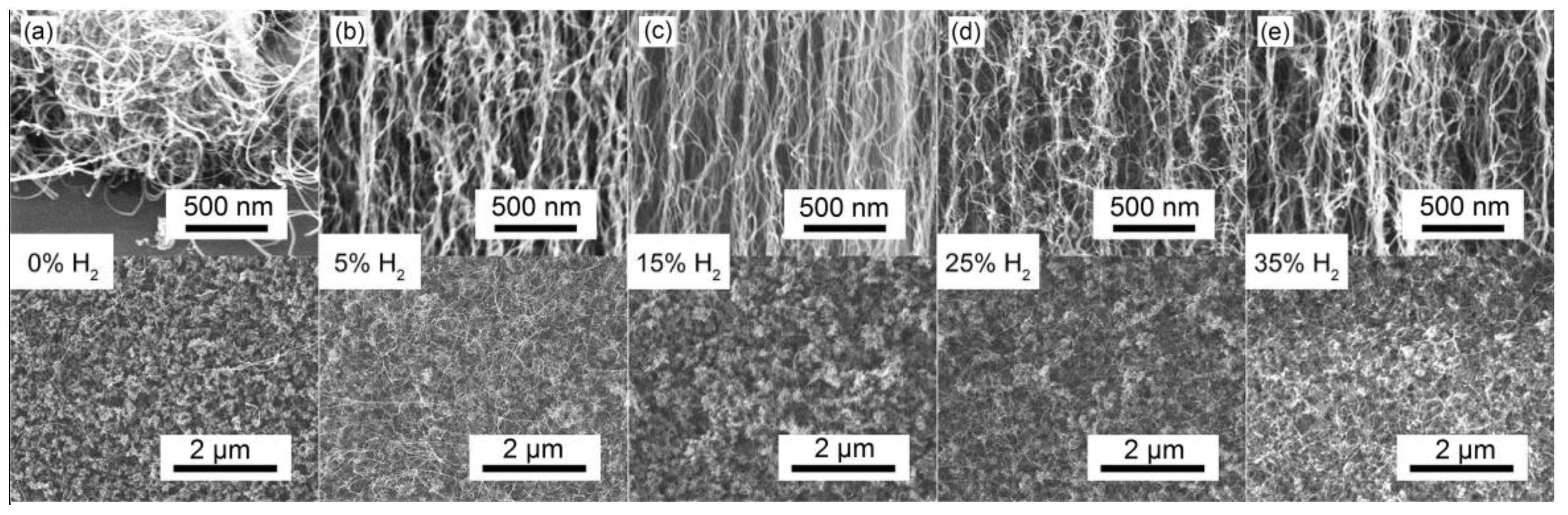
Figure 2.
Heights of VACNTs synthesized under various hydrogen concentrations.

Figure 3.
TEM images of single VACNTs prepared under different H2 concentrations: (a) 5%; (b) 15%; (c) 25%; (d) 35%.
Figure 3.
TEM images of single VACNTs prepared under different H2 concentrations: (a) 5%; (b) 15%; (c) 25%; (d) 35%.
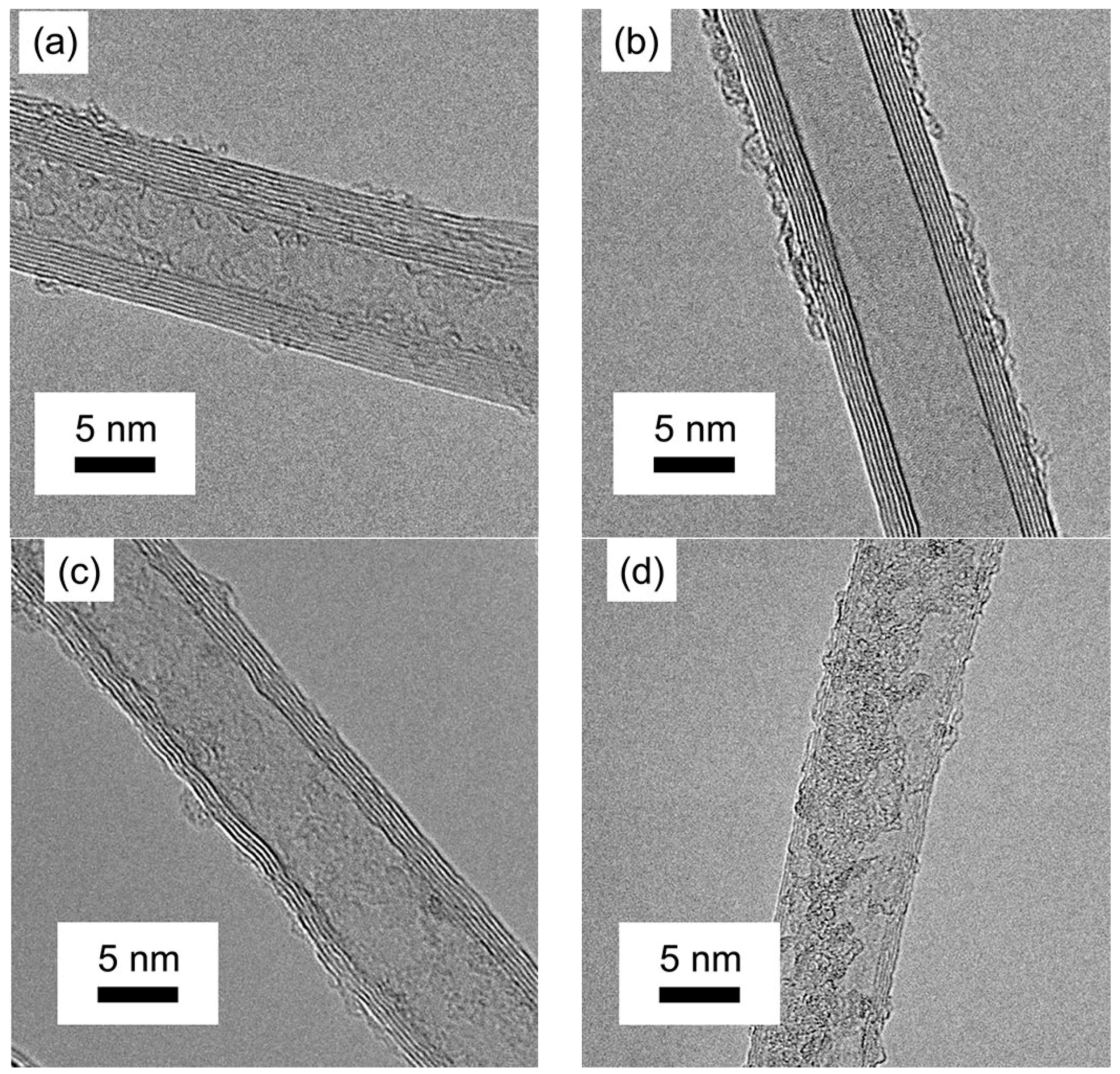
Figure 4.
Raman spectra of VACNTs created under various hydrogen concentrations.

Figure 5.
Atomic force microscopy (AFM) analysis of catalyst surface after chemical vapor deposition (CVD) process under different H2 concentrations: (a) 5%; (b) 15%; (c) 35%. (d) The influential mechanism model of hydrogen concentration on the structure of VACNTs.
Figure 5.
Atomic force microscopy (AFM) analysis of catalyst surface after chemical vapor deposition (CVD) process under different H2 concentrations: (a) 5%; (b) 15%; (c) 35%. (d) The influential mechanism model of hydrogen concentration on the structure of VACNTs.

Figure 6.
(a) The hanging-weight system to test the shear adhesive strength of VACNTs; (b) The schematic diagram of the shear adhesive strength test process; (c) The shear adhesive strength of VACNTs prepared under different hydrogen concentrations; (d) The shear adhesive durability of VACNTs.
Figure 6.
(a) The hanging-weight system to test the shear adhesive strength of VACNTs; (b) The schematic diagram of the shear adhesive strength test process; (c) The shear adhesive strength of VACNTs prepared under different hydrogen concentrations; (d) The shear adhesive durability of VACNTs.
© 2017 by the authors. Licensee MDPI, Basel, Switzerland. This article is an open access article distributed under the terms and conditions of the Creative Commons Attribution (CC BY) license (http://creativecommons.org/licenses/by/4.0/).
Share and Cite
MDPI and ACS Style
Li, Y.; Ji, K.; Duan, Y.; Meng, G.; Dai, Z. Effect of Hydrogen Concentration on the Growth of Carbon Nanotube Arrays for Gecko-Inspired Adhesive Applications. Coatings 2017, 7, 221. https://doi.org/10.3390/coatings7120221
AMA Style
Li Y, Ji K, Duan Y, Meng G, Dai Z. Effect of Hydrogen Concentration on the Growth of Carbon Nanotube Arrays for Gecko-Inspired Adhesive Applications. Coatings. 2017; 7(12):221. https://doi.org/10.3390/coatings7120221
Chicago/Turabian StyleLi, Yang, Keju Ji, Yali Duan, Guiyun Meng, and Zhendong Dai. 2017. "Effect of Hydrogen Concentration on the Growth of Carbon Nanotube Arrays for Gecko-Inspired Adhesive Applications" Coatings 7, no. 12: 221. https://doi.org/10.3390/coatings7120221
Note that from the first issue of 2016, this journal uses article numbers instead of page numbers. See further details here.