Spin Coating on Spherical Surface with Large Central Angles

1
Key Laboratory of Thin Film and Optical Manufacturing Technology, Ministry of Education, Xi’an Technological University, Xi’an 710032, China
2
State Key Laboratory for Manufacturing Systems Engineering, Xi’an Jiaotong University, Xi’an 710049, China
3
School of Optoelectronic Engineering, Xi’an Technological University, Xi’an 710032, China
*
Author to whom correspondence should be addressed.
Coatings 2017, 7(8), 124; https://doi.org/10.3390/coatings7080124
Submission received: 17 July 2017
/
Revised: 4 August 2017
/
Accepted: 11 August 2017
/
Published: 14 August 2017
Abstract
:Spin coating is one of the dominant processes for producing photoresistant thin films in integrated circuit manufacturing. The application of this process mainly focuses on flat surfaces. With the development of science and technology, the spin coating process is no longer restricted to flattened geometry. The demand for uniform thin films on curved surfaces urgently needs to be met, such as for the fabrication of anti-electromagnetic metal shielding grids on the window of fairings and grating on spherical lens. This is a challenging problem, and a fundamental mechanism is indispensable to provide guidance. However, few models have been reported about spinning a coating on curved geometry with a large central angle. To provide support for solving the problem of spin coating on a spherical surface with a large central angle, this paper presents a formulation for modeling the spin coating process on a spherical surface with a central angle close to 90 degrees and experiments that were completed to validate it. The film thickness evolution and uniformity of film thickness on a spherical surface are studied using this model and are compared with the existing literature to determine the potential advantages of the new model. Simulation results show that the uniformity of final film thickness is not ideal for uniform initial film thickness distribution. One dimensionless parameter is defined as the dominating factor to control film thickness and uniformity, which is related to the processing parameters. As demonstrated by the experimental results, this model can be adopted to predict film the thickness profile on spherical surfaces with large central angles.
1. Introduction
The process of spin coating is one of the dominating techniques for producing uniform thin films on flat surfaces in the order of micrometers or nanometers. It is widely applied in depositing photoresist layers on silicon substrates. With the popularity of this process in industry, research about the process has continued for more than seventy years. Primary research on spin coating is focused on the coatings on planar surfaces. The precursive research of spin coating was performed by Emslie et al. in the late 1950s [1]. In that model, they studied the flow of a Newtonian liquid on an infinite flat substrate spinning at a constant angular speed. They analyzed the mechanism of the spin coating process from the point of fluid mechanics. Besides providing an analytical model, the authors also predicted the film profiles with different initial contours. Soon, Emslie’s model was extended to non-Newtonian liquids of the power law model, the Bingham-plastic model, etc. [2,3]. However, both models were established without considering the effect of evaporation. Later, Meyerhofer [4] developed a modified model to accommodate the effects of evaporation on the spinning solution. The predictions from the new model were validated against experimental results. Compared to Emslie’s model, Meyerhofer’s model considered uniform evaporation and variable viscosity. Correspondingly, Emslie’s model did not take evaporation into account and assumed viscosity as a constant in the process. It was shown that Meyerhofer’s model and its variants apparently correlated to the real film thickness found in practice. Nevertheless, it was also demonstrated by experiments that the effect of evaporation depended on the materials that are coated on. If the material has a very low evaporation coefficient, such as epoxy, the effect of evaporation can be neglected. As the research about spin coating proceeded, more details of the process were taken into account [5,6,7]. Bornside [8] developed a one-dimensional model of spin coating including variations of solution concentrations, viscosity, and diffusivity across the film thickness. The difference between Bornside’s model and Meyerhofer’s model was whether the film thickness and concentration were variable. For the complex equations in Bornside’s model, Full Newton Iteration Method (FNIM) was utilized to obtain solutions. The experimental results of Bornside’s model agreed with most previous reports. At the time of Bornside’s research, the coating of magnetic film on disks was a hot topic, as many problems existed in the fabrication of magnetic disks. To solve such problems containing more complex conditions, Bornside built a two-dimensional model [9,10]. The two-dimensional model can predict film thickness with a viscosity depending on shear rate in the process. The two-dimensional model can predict film thickness on non-uniform flat substrate. To gain more understanding of the planarization process in microelectronic processing, the two-dimensional model was applied to spin coating of a grooved substrate. With the two-dimensional model, Bornside also explained the mechanism of spin coating of magnetic material on a disk. To apply spin coating of thin films on substrates in practice, more experiments and models were built on the basis of Emslie’s model, Meyerhofer’s model, and Bornside’s model. After these models and experiments were reviewed, it was found that they were all suitable for flat surfaces without considering other geometries.
However, the spin coating process was not only limited to the shape of a flat surface. The research of spin coating was extended to curved surfaces with increasing applications of optical elements including curved gratings, diffractive optical elements, and a metal shielding grid on the window of fairing [11,12,13,14]. As the optical elements were mainly fabricated by photolithography, uniform photoresist film coated on curved substrates was important [15,16,17,18]. In several papers, the problem of coating films on concave surface and convex surface was analyzed [19,20]. The authors built models based on Emslie’s model for flat surface and obtained solutions following the same method Emslie used for spin coating on flat surface without considering the effect of a curved substrate [1]. The models were suitable for spin coating on a spherical surface with a small central angle. When the central angle of a sphere surface is small, the sphere surface is close to a flat surface. In such conditions, Emslie’s model can be appropriately extended to the modeling of spin coating on a spherical surface. Meanwhile, it can be observed from previous reports that the uniformity of film is good when the central angle of the sphere is small. This conforms to the prediction in Emslie’s paper about spin coating on spherical surfaces with the central angle no larger than 20 degrees [1]. However, few papers analyze the problem of spin coating on spherical surface when the central angle is large, especially when the central angle is close to 90 degrees.
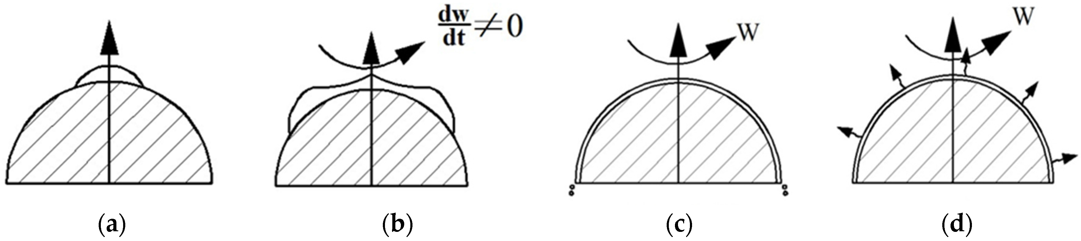
To provide support for solving the problem of spin coating on a spherical surface with a large central angle, this paper focuses on film thickness evolution on a spherical surface with a central angle close to 90 degrees in the spin-off stage. Spin-off is one of the four stages of the spin coating process: deposition, spin-up, spin-off, and evaporation, as shown in Figure 1.
Spin-off and evaporation are the stages that have the most impact on the uniformity of film thickness. In this paper, we build a model and obtain numerical solutions by simulations for the spin-off stage. The model in this paper agrees with the models in the literature when the central angle of the spherical surface is small [18,19,20]. However, when the central angle of the spherical surface is large, the film thickness coated will be different from the model in this paper compared to the literature [19,20]. The advantage of this model, compared to the literature, is that it can predict film thickness profile evolution on a spherical surface with a large central angle. Meanwhile, in this model, the dependence of film thickness on the position on the spherical surface is considered. The uniformity of the film thickness profile is an important parameter for optimizing the spin coating process. Unlike the coating on a planar surface, the uniformity of film thickness on a spherical surface is not ideal, even given uniform initial film distribution, which is consistent with the literature [19,20]. To obtain uniform film thickness coated on a spherical surface, we need to optimize the process parameters, which is our plan for the next step. The objective of this paper is to provide equations to predict the film thickness distribution on a spherical surface, whether the central angle of the spherical surface is large or small. The derivation and simulation process may provide reference for other curved geometries. In addition, the results of this paper might provide guidance for innovation in spin coating equipment. To validate the equations provided in this work, experiments were designed and executed to check film thickness distribution and the uniformity of the film thickness on a spherical surface.
2. Mathematical Model
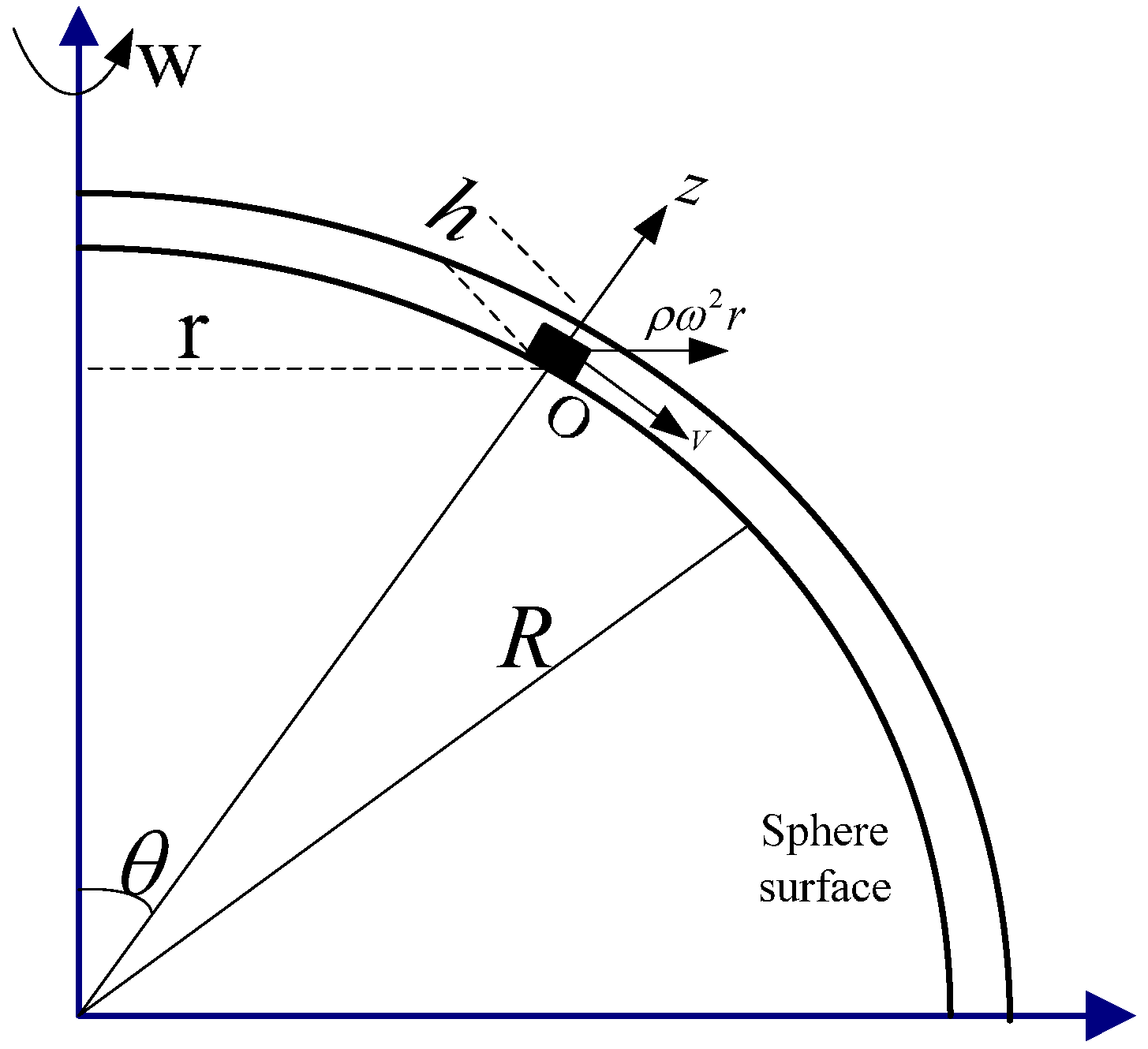
The schematic diagram of the spin coating process on a spherical surface is shown in Figure 2. The actual process is complex, with coupled momentum, mass, and energy transport. To simplify the process, the following assumptions were made in this work:
- (1)
- The liquid is incompressible and homogenous, which means the density of fluid ρ is constant in the process;
- (2)
- The liquid is a Newtonian fluid;
- (3)
- Lubrication approximation is adopted;
- (4)
- Evaporation is negligible;
- (5)
- Gravitational force and Coriolis force are not considered.
As shown in Figure 2, several processing parameters involved in the process are defined.
The momentum equation of unit volume of liquid on the spherical surface can be expressed in Euler method with Equation (1).
In Equation (1), η is viscosity of the fluid. The relationship between r and R can be obtained from the geometry with Equation (2).
As lubrication approximation is adopted, the following boundary conditions can be obtained. At the spherical surface, where z = 0, the boundary conditions are expressed as Equations (3) and (4).
At the top surface of the film, where z = h,
The velocity profile of the film can be obtained by integration of Equation (1), as shown in Equation (5).
The flux q along V direction for unit horizontal circumference can be obtained by Equation (6).
Substituting Equation (5) into Equation (6), q can be obtained using Equation (7),
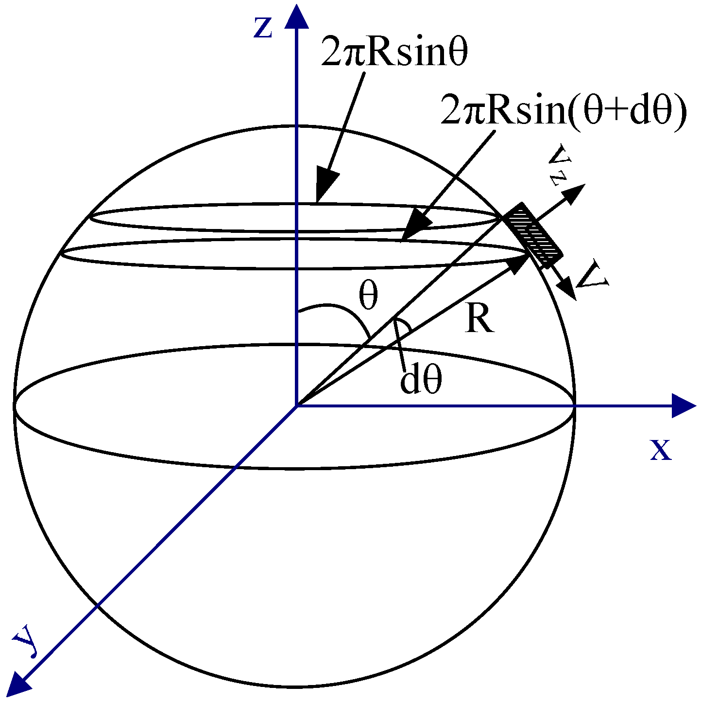
Besides the momentum equation, the mass balance equation is indispensable. The mass balance equation can be derived by making a balance of total mass over a differential annular shell, as shown in Figure 3.
The inflow plane is taken at the position θ and the outflow plane is taken at the position θ + dθ. The inflow of total mass is,
In the formula, q(θ) is the flux at the position θ as defined in Equation (7). The outflow of total mass for the control volume is,
The accumulation of mass in the control volume is,
From the definition of mass conservation, the accumulation of mass in the control volume equals the difference between the inflow of mass and outflow of mass. Combining the terms, the governing equation for film thickness evolution on spherical surface can be obtained in Equation (8).
In Equation (8), the film thickness h is related to the position θ and time t. h can be expressed as Equation (9),
Analytical solutions for Equation (8) are not easy to obtain. However, numerical solutions for this equation at specified spinning parameters can be obtained by simulations.
3. Results and Discussion
3.1. Numerical Simulation
To solve the governing Equation (8) for the film thickness evolution on a spherical surface, numerical methods are utilized when it is not easy to obtain analytical results. Equation (8) can be expanded to Equation (10) by using the definition of derivatives so that the boundary conditions for Equation (8) can be directly employed.
where, the coefficient k can be obtained with Equation (11),
The boundary condition for Equation (10) is Equation (12), at θ ≈ 0,
This boundary condition for Equation (12) is obtained from the symmetric geometry of the final film coat, which is verified by experiments [19,20]. As the sphere is axis-symmetric, the film thickness at symmetric positions should be equal. For this reason, at the acme where θ = 0, the film should be continuous and the derivative ∂h/∂θ should be zero. However, θ cannot be zero for Equation (8) from the modeling process. Thus, a positive value close to zero is assigned to θ in simulation process.
With the governing Equation (8) and boundary condition Equation (12), the film thickness evolution under different initial conditions can be obtained. The initial conditions include uniform thickness at the initial stage and uniform thickness distribution after a certain time of spin-off. In this work, we analyzed the film thickness profile evolution with the initial uniform thickness distribution on the substrate and compared the results with literature under the same conditions. In addition, we made efforts to obtain the initial film thickness configuration on the substrate in order to achieve uniform film thickness after a certain time of spinning.
3.1.1. Uniform Initial Film
If the spherical surface is covered by uniform film at the beginning of spin-off stage, the film thickness profile after a certain time can be obtained with the numerical solution of Equation (8). In fact, the film thickness profile evolution with a uniform initial film thickness has been simulated in the existing models for a concaved or convex surface [19,20]. Therefore, the results of the model in this paper will be compared with the data in literature to find out the difference between the models.
In this situation, the initial condition for Equation (8) is Equation (13), when t = 0,
Both the explicit method and implicit method are utilized to obtain numerical solutions for Equation (8). The results are identical with the two methods. To demonstrate the intrinsic discipline with the methods, one dimensionless parameter is defined in Equation (14).
In Equation (14), T is dimensionless time, k is the spin parameter as defined in Equation (11), h0 is the initial film thickness, and t is the processing time. As a governing single parameter, T is effective in analyzing the film thickness evolution and distribution on the spherical surface. Compared to the several control parameters including k, h0, and t, T is more effective for directly investigating the change of film thickness and uniformity development in the coating process. With T as a combination of the processing parameters and initial conditions, the value should be in a range to obtain real solutions for the film thickness. As parts of k are physical parameters of the material, the value of T is mainly varied according to the spinning speed and processing time so that the simulation results can be compared with experimental data. Particularly, to predict the film thickness with good precision for a large central angle, the value of T cannot be too small to obtain too large a variation on the sphere edge. For the uniform initial film thickness, the film thickness profile at different T can be obtained in Figure 4. The film thickness is smaller at larger T. At the same T, the variation of the film thickness will be larger at larger θ. Therefore, the film will be thinner with a large dimensionless parameter T. This indicates that T should be controlled to a designed high value if we intend to obtain very thin film.
The schematic of film contour evolution by the spin coating process can be obtained in Figure 5. It shows the evolution of a film contour coated on a spherical substrate with R = 0.02 m. The initial film thickness is set to be 8 × 10⁻⁴ m, and the dimensionless T is 2. With such parameters, the final film contour is shown in blue. The film becomes thicker at the edge. In order to characterize the uniformity of the film thickness, one parameter is defined in Equation (15).
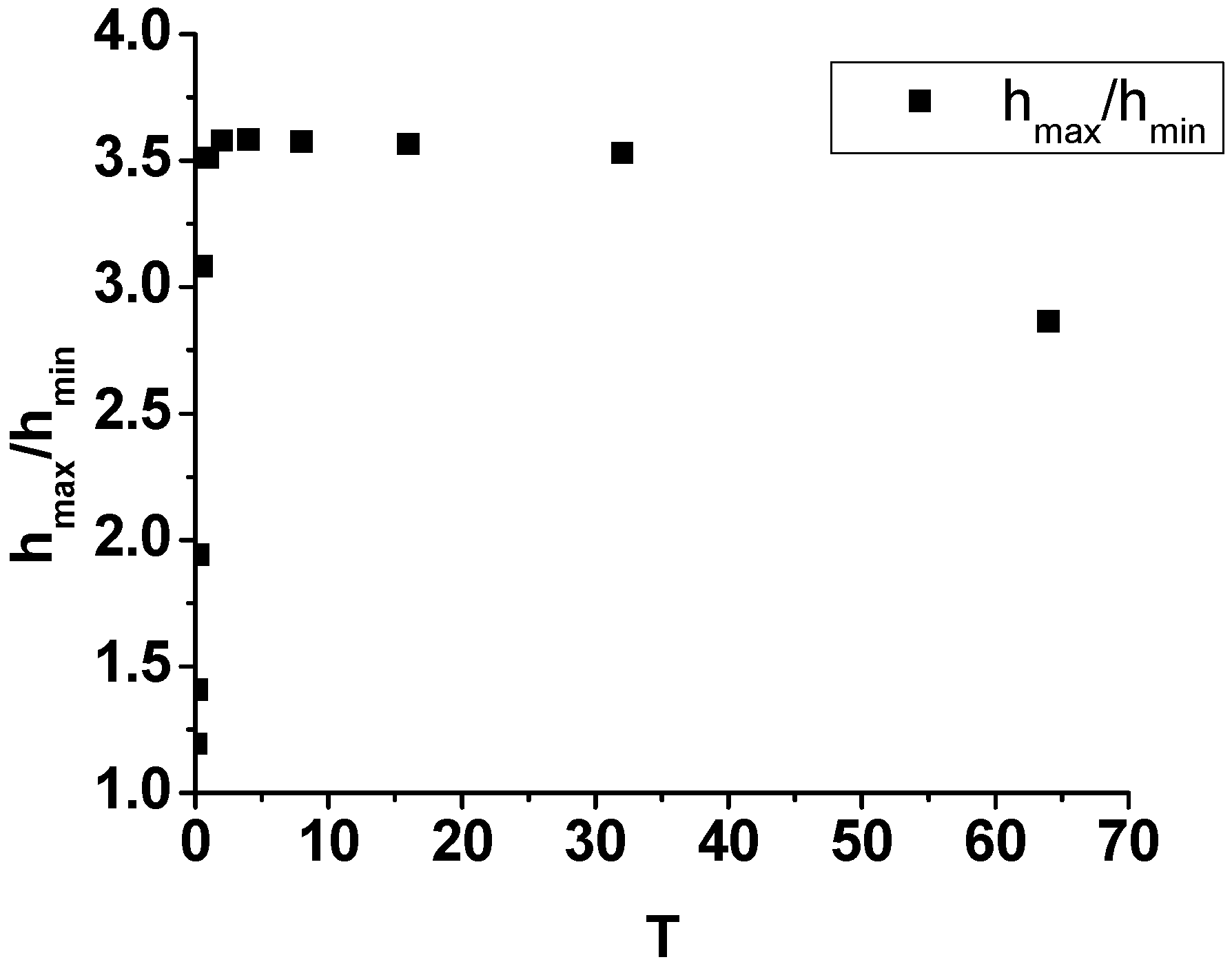
In Equation (15), u is defined to investigate the difference of film thickness on the surface at a specified time. hmax is the largest film thickness on the surface, while hmin is the smallest value of film thickness on the surface. The change in the uniformity of film thickness with dimensionless time T can be observed in Figure 6. In order to obtain the discipline of uniformity changes with T, T is set as the power of 2. The corresponding data is in Table 1. The uniformity of film thickness is better when T is smaller if T is no more than 16. However, if T is more than 16, the uniformity will be better when T is larger.
The film thickness profile evolution with different dimensionless T can also be obtained for the models in the literature [19,20]. The difference between the model in this paper and the models in the literature can be obtained from the film thickness profile at different T, as shown in Figure 7.
The figure of comparison shows that the model in the literature is suitable for a small central angle (θ). The model in this paper can also predict the film thickness evolution for a small θ. The difference between this model and the model in the literature is the component ∂h/∂θ in the governing equation. The model in the literature predicts the film thickness evolution for a uniform initial thickness profile with an assumption of ∂h/∂θ = 0. The model in this paper can predict a film thickness of a large angle θ at a larger T by taking account of ∂h/∂θ. Compared to the model in this paper, the model in literature can just predict film thickness profile in a certain range of T. If T is large enough, the film thickness at large angle cannot be predicted by the model in the literature. Meanwhile, the film thickness formed by the two models are different. The film thickness is almost the same for the two models when T is small, but the film thickness formed by the model in this paper is smaller when T is large.
3.1.2. Non-Uniform Initial Film
Ideally, the initial film thickness distribution is uniform on the spherical surface for the spin-off stage in this work. The film thickness evolution and the uniformity of film thickness is analyzed as above. In the case of a non-uniform initial film thickness distribution, the film thickness profile evolution can be obtained as below. Assuming the initial condition for Equation (8) is Equation (16), when t = 0,
Under the same boundary conditions, the film thickness evolution can be numerically solved using dimensionless parameter T. The profile is shown in Figure 8. The film thickness profile shows a similar trend to that with a uniform initial film distribution. The film will be thicker when the location is further from the center. Besides, the thickness variation will be more significant with the increase of dimensionless parameter T. In this work, the initial profile of h0sin θ, and dimensionless T changing from 2 to 8 are used as a case to investigate film thickness evolution with non-uniform initial thickness distribution. The film thickness is smaller with the increase of T, while the thickness variation from the center to the edge will be larger by increasing T.
The film thickness distribution on a spherical surface by spin coating with a non-uniform initial film thickness is also studied with another type of initial contour to provide comprehensive support. The initial contour used is, when t = 0,
With the defined dimensionless parameter T, the film thickness evolution under such an initial profile is shown in Figure 9. T, changing from 2 to 8, is used as an example to check the film thickness evolution trend. The film will be thinnest when T = 8. Film thickness is inversely related to T. For the film distribution on a spherical surface, the thickness shows a trend of slowly increasing from the center to the edge when θ is in a certain range (θ ≤ 0.9, in this example). Out of this range, the film thickness shows a sharp decrease when θ increases, which closely follows the contour of the initial film profile. As shown in Figure 9, uniformity of the final film distribution can also be inferred from the curves. In the specified range (θ ≤ 0.9), the film shows good uniformity when T is small. With an increase of T, the film thickness is smaller, and the uniformity becomes worse. In this example, when θ is larger than 0.9, the final film thickness distribution follows the trend of the initial contour (h0cos θ). With the designed non-uniform initial film thickness distribution, the uniformity in this range (θ > 0.9) is quite low.
3.2. Experimental Validation
In this work, the film thickness evolution on a spherical surface by spin coating is predicted with the proposed model. The model is built for the spin-off stage without considering evaporation effect. Two cases of uniform initial film and non-uniform initial film are used as examples to check the film profile with the model. Based on the numerical results, the final film profile is mainly controlled by the dimensionless parameter T. Nevertheless, the aforementioned results are obtained with modelling and numerical simulation. Experiments are necessary to check the film thickness distribution on a spherical surface to validate this model.
3.2.1. Materials
Araldite® LY8601 (base resin)/Aradur® 8602 (hardener), obtained from Huntsman Advanced Materials Americas LLC (Salt Lake City, UT, USA), was used as a resin system for spin coating. This two-component epoxy was chosen because of its low viscosity and it undergoes almost no evaporation during spin coating. In addition, it can be rapidly cured after coating. The base resin is a blend of DGEBA with diluents of mono-functional epoxy compounds. The base/hardener ratio is 4:1 by weight, as suggested by the supplier. The mixture was stirred for 2 min at room temperature and then degassed in a vacuum oven before spin coating.
The substrate used is a plano convex lens with focal length of 60 mm, back working distance of 53.9 mm, the curvature radius is 31 mm. The material of this convex lens is H-K9L glass. In the experiment, epoxy was coated on the convex surface and then film thickness was measured using a self-designed system based on a spectrometer.
3.2.2. Measurement
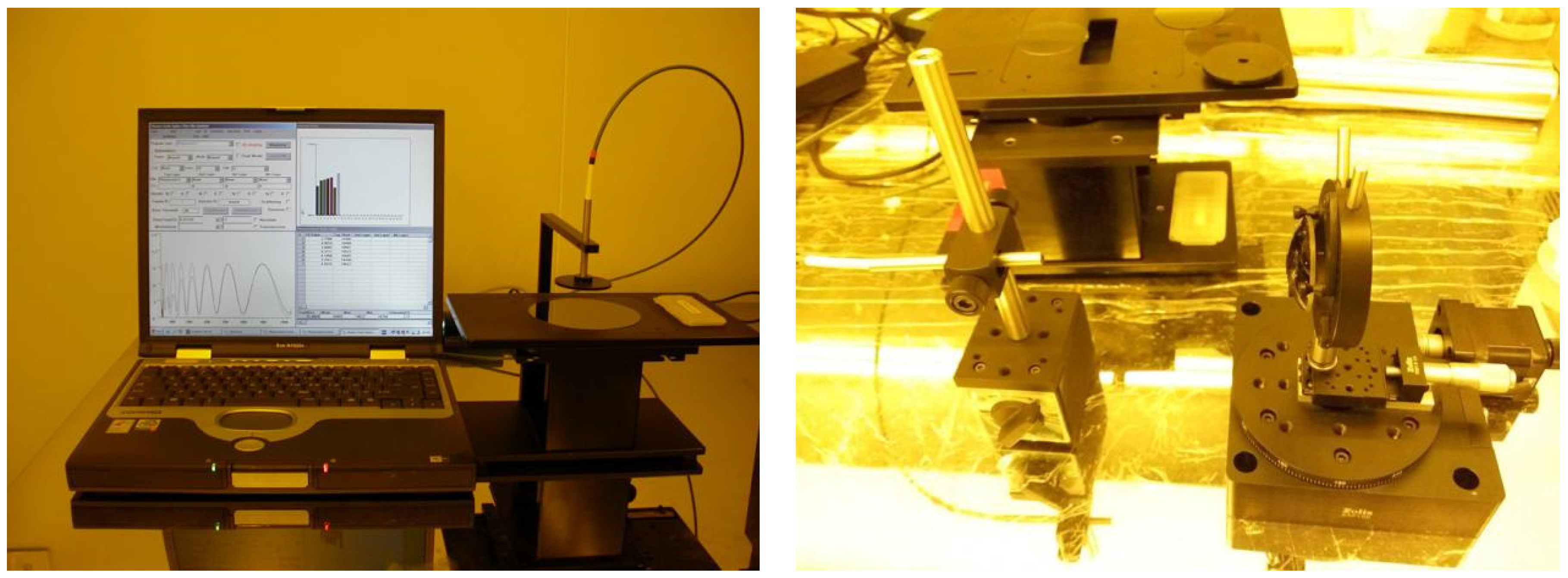
The thickness of film was tested by the modified film thickness tester MP-100s (Mission Peak Optics Inc., Fremont, CA, USA) with one self-designed rotary table. The working principle of the tester is as follows: co-axial optical fiber emits light to the sample surface, and reflected light is received by the optical fiber and transmitted to spectrometer to analyze the film thickness information. Thus, the optical fiber detector can be perpendicular to the tested surface. The self-designed measurement system is shown in Figure 10. First, the lens is installed on a precise translation stage. Then, the stage is assembled to the rotary table while ensuring that the sphere center of the lens is consistent with the center-axis of the rotary table so that the optical fiber detector can be kept perpendicular to the lens surface to measure film thickness when the rotary table is rotating.
3.2.3. Experimental Setup
As listed in the Equations (10) and (11), material property plays an important role in determining film thickness. In this work, the mixture density ρ and viscosity η was obtained using a parallel plate rheometer (AR 2000EX, TA Instruments, New Castle, DE, USA) and a liquid densimeter (DDM2911-S3-plus, Rudolph, Hackettstown, NJ, USA). The spin speed ω and spin time t were adjusted on a spin coater (KW-5, Institute of Microelectronics of CAS, Beijing, China) to obtain films with different thickness. In the experiment, the initial film contour is hard to obtain. A droplet with a constant volume of mixed solution was used in all experiments to ensure repeatability. After the coating process was completed, epoxy on the convex surface was cured in minutes. The thickness of the film was tested by the modified film thickness tester MP-100s with one self-designed rotary table.
3.2.4. Experimental Results
In the designed experiment, epoxy was selected as the material for model validation. According to the hypothesis, the model is built for a Newtonian fluid. Thus, the viscosity of the epoxy needs to be examined to assure it meets these requirements. The result is shown in Figure 11. The viscosity of the epoxy at 90 °C keeps almost constant in the initial 100 s, which demonstrates that the mixture shows Newtonian behavior and fits with the model assumptions. Furthermore, a heated mixture was used in this experiment. The purpose was to accelerate the curing process of the epoxy to maintain the film thickness obtained by spin coating.
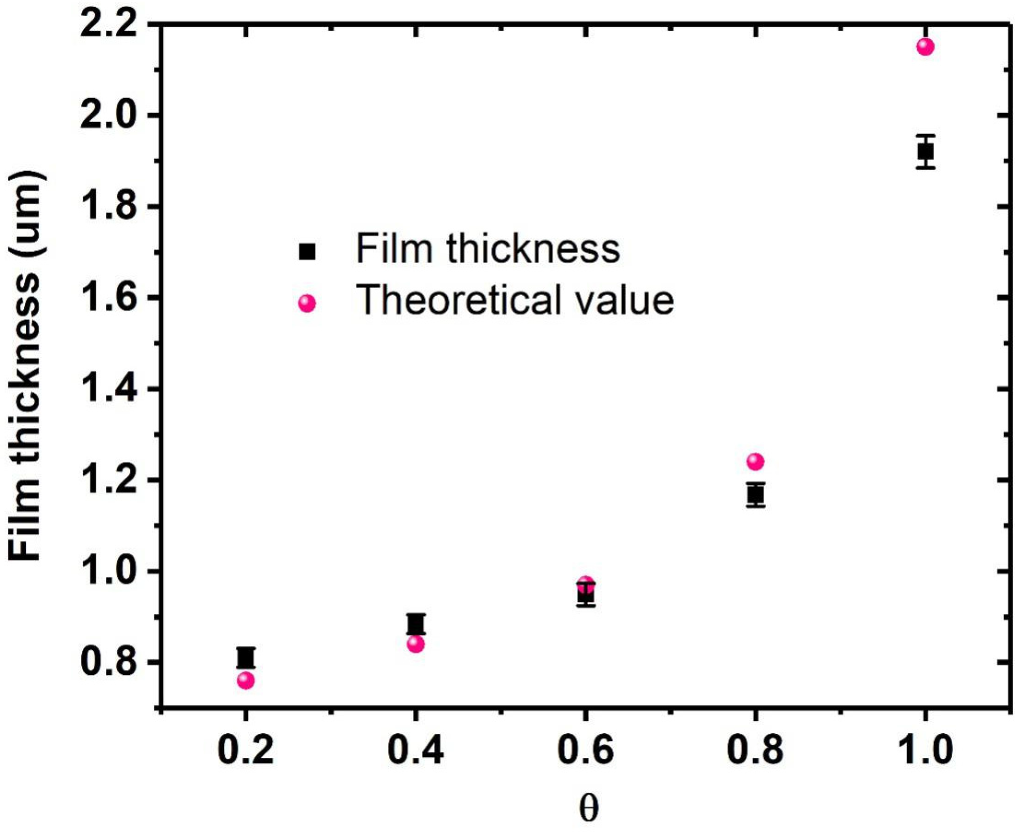
Films were obtained by spin coating on a spherical surface, and the thickness of the films was measured to validate the proposed model. The tested data at five spots on the surface were compared with theoretical value calculated using the model, as shown in Figure 12. The film thickness at θ = 0.2, 0.4, 0.6, 0.8, and 1.0 on the same circle through vertex was repeatedly tested, and the average value with standard error is shown in the figure. The experimental values fit well with the calculated theoretical numbers. Particularly, when θ is small (θ ≤ 0.6), the difference between them is tiny. The experimental value at the edge has a relatively large variation from the calculated one. One possible reason is that high linear speed causes shear, thinning of the fluid to obtain a thinner film.
4. Conclusions
A model for calculating film thickness by spin coating on a spherical surface with a large central angle was proposed in this work. Compared to the existing work in the literature, this model can be used to predict the film thickness distribution on a spherical surface with a central angle over 20°. The model was compared with the work in the literature and validated with experiments. The results show that the calculated film thickness using this model was highly consistent with the measured value on a spherical surface. Thus, it can be inferred that the model can be used to guide spin coating on a spherical surface with a large central angle (0° < θ < 90°). A dominating dimensionless parameter T is found, which is a function of material property (ρ, η) and spinning parameters (h0, ω). By adjusting T, we can obtain the film thickness distribution needed. This work demonstrates the feasibility of predicting and controlling spin coating on a curved substrate. More work can be done based on this work, including considering evaporation effect and non-Newtonian fluid behavior, which will be the task of the next step. In addition, this work is helpful in designing new spin coating devices that can adjust substrate temperature, program spinning speeds, and so on to obtain a uniform film on a curved substrate.
Acknowledgments
This work was supported by State Key Laboratory for Manufacturing System Engineering (Grant No.SKLMS2017003), State Key Laboratory of Robotics and System (HIT) (Grant No. SKLRS-2017-KF-03) and National Key Research & Development (R&D) plan (2016YFB0501604).
Author Contributions
Huan Liu and Xudong Fang completed the modeling and simulation and designed the experiments; Le Meng performed the spin coating experiments and tested the result; Shanshan Wang analyzed the data.
Conflicts of Interest
The authors declare no conflict of interest.
References
- Emslie, A.G.; Bonner, F.T.; Peck, L.G. Flow of a viscous liquid on a rotating disk. J. Appl. Phys. 1958, 29, 858–862. [Google Scholar] [CrossRef]
- Acrivos, A.; Shah, M.J.; Petersen, E.E. On the flow of a non-Newtonian liquid on a rotating disk. J. Appl. Phys. 1960, 31, 963–968. [Google Scholar] [CrossRef]
- Jenekhe, S.A.; Schuldt, S.B. Flow and film thickness of bingham plastic liquids on a rotating disk. Chem. Eng. Commun. 1985, 33, 135–147. [Google Scholar] [CrossRef]
- Meyerhofer, D. Characteristics of resist film produced by spinning. J. Appl. Phys. 1978, 49, 3993–3997. [Google Scholar] [CrossRef]
- Hall, D.B.; Underhill, P.; Torkelson, J.M. Spin coating of thin and ultrathin polymer films. Polym. Eng. Sci. 1998, 38, 2039–2045. [Google Scholar] [CrossRef]
- Mitzi, D.B.; Kosbar, L.L.; Murray, C.E.; Copel, M.; Afzali, A. High-mobility ultrathin semiconducting films prepared by spin coating. Nature 2004, 428, 299–303. [Google Scholar] [CrossRef] [PubMed]
- Lawrence, C. The mechanics of spin coating of polymer films. Phys. Fluids 1988, 31, 2786–2795. [Google Scholar] [CrossRef]
- Bornside, D.E.; Macosko, C.W.; Scriven, L.E. Spin coating: One-dimensional model. J. Appl. Phys. 1989, 66, 5185–5193. [Google Scholar] [CrossRef]
- Bornside, D.E.; Macosko, C.W.; Scriven, L.E. On the modeling of spin coating. J. Imaging Technol. 1987, 13, 122–130. [Google Scholar]
- Bornside, D.E. Mechanism for the local planarization of microscopically rough surfaces by drying thin films of spin-coated polymer/solvent solutions. J. Electrochem. Soc. 1990, 137, 2589–2595. [Google Scholar] [CrossRef]
- Gupta, V.K.; Abbott, N.L. Design of surfaces for patterned alignment of liquid crystals on planar and curved substrates. Science 1997, 276, 1533–1536. [Google Scholar] [CrossRef]
- Brytsche, H.H.; Farley, E.D.; White, S.S. Method for Spin Coating a Multifocal Lens. U.S. Patent 5,753,301, 19 March 1998. [Google Scholar]
- Blackburn, W.P.; Bowles, R.J., III; Levesque, M.B.; Maldonado, E. Spin and Spray Coating Process for Curved Surfaces. U.S. Patent 6,352,747, 5 March 2002. [Google Scholar]
- Brassard, J.-D.; Sarkar, D.K.; Perron, J. Fluorine based superhydrophobic coatings. Appl. Sci. 2012, 2, 453–464. [Google Scholar] [CrossRef]
- Chen, L.J.; Liang, Y.-Y.; Wang, K.W.; Luo, J.-B.; Zhang, C.-H.; Liang, J.-Y.; Yang, G.G. Research on the optical field distribution and micro-fabrication model in convex-surface laser lithography. Opt. Commun. 2010, 283, 2631–2639. [Google Scholar] [CrossRef]
- Xie, Y.; Lu, Z.; Li, F.; Zhao, J.; Weng, Z. Lithographic fabrication of large diffractive optical elements on a concave lens surface. Opt. Express 2002, 10, 1043–1047. [Google Scholar] [CrossRef] [PubMed]
- Xie, Y.; Lu, Z.; Li, F. Fabrication of large diffractive optical elements in thick film on a concave lens surface. Opt. Express 2003, 11, 992–995. [Google Scholar] [CrossRef] [PubMed]
- Lenz, M.; Mazzon, C.; Dillmann, C.; Gerhardt, N.C.; Welp, H.; Prange, M.; Hofmann, M.R. Spectral domain optical coherence tomography for non-destructive testing of protection coatings on metal substrates. Appl. Sci. 2017, 7, 364. [Google Scholar] [CrossRef]
- Chen, L.; Liang, Y.-Y.; Luo, J.-B.; Zhang, C.-H.; Yang, G.G. Mathematical modeling and experimental study on photoresist whirl-coating in convex-surface laser lithography. J. Opt. A Pure Appl. Opt. 2009, 11, 105408. [Google Scholar] [CrossRef]
- Feng, X.G.; Sun, L.C. Mathematical model of spin-coated photoresist on a spherical substrate. Opt. Express 2005, 13, 7070–7075. [Google Scholar] [CrossRef] [PubMed]
Figure 1.
Schematic of four stages of spin coating process: (a) deposition, (b) spin up, (c) spin off, and (d) evaporation.
Figure 1.
Schematic of four stages of spin coating process: (a) deposition, (b) spin up, (c) spin off, and (d) evaporation.

Figure 2.
Schematic of spin coating on spherical surface. r is the horizontal distance from a position on the spherical surface to the vertical axis; θ is the central angle between a position on the spherical surface and the vertical axis; h is the film thickness at a specified position on the spherical surface; V is the tangential velocity of fluid at a position on the spherical surface; z is the distance from spherical surface along normal direction; R is the radius of the sphere; ω is the angular velocity of the sphere rotating along vertical axis.

Figure 3.
Annular control volume on spherical surface.

Figure 4.
Film thickness evolution at different dimensionless time T.
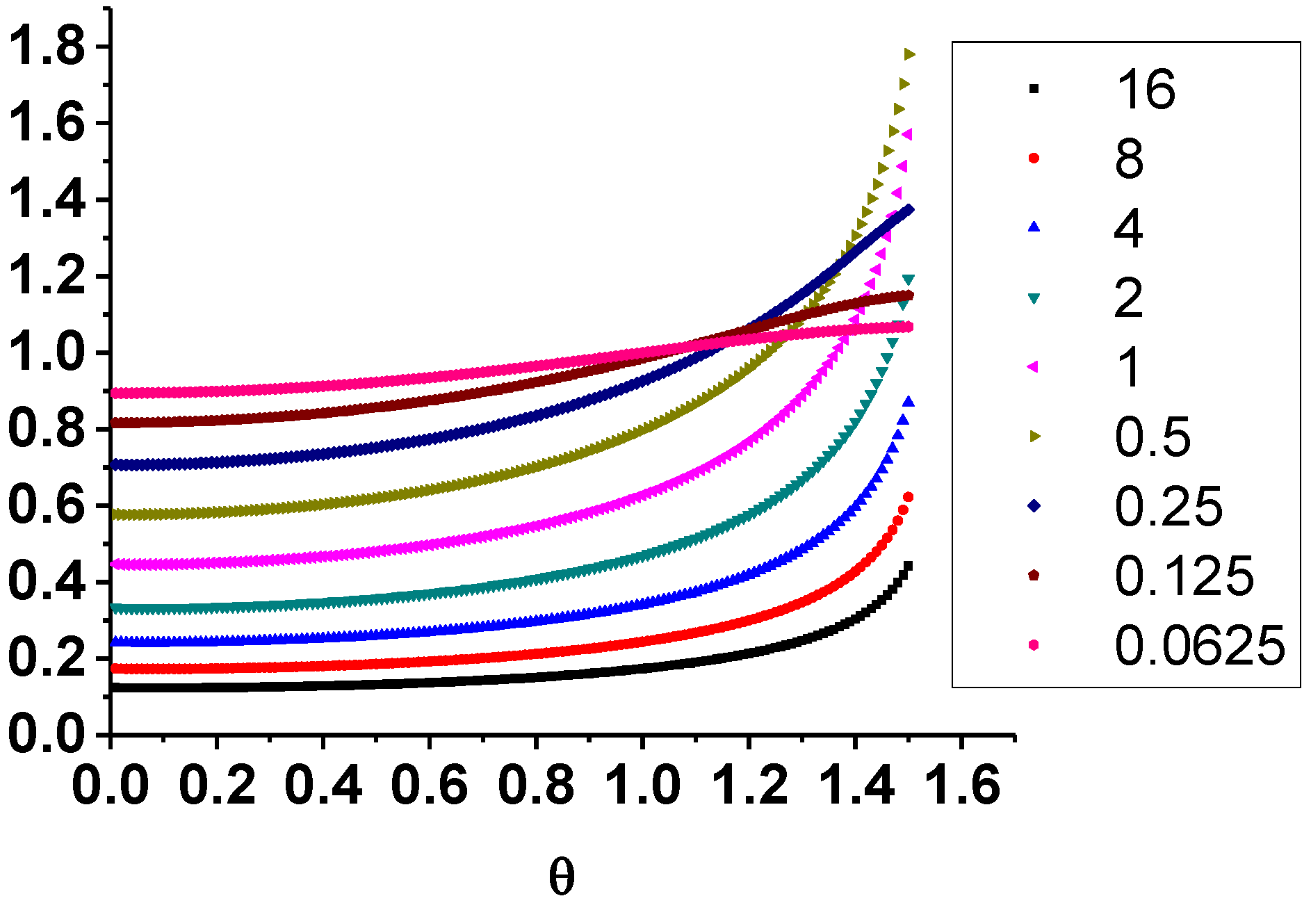
Figure 5.
Schematic of film contour evolution on a sphere.
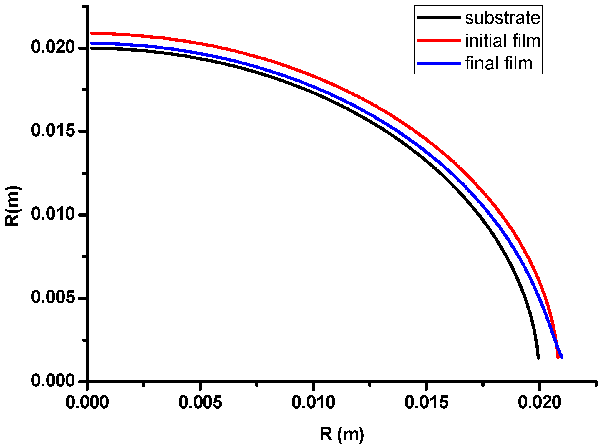
Figure 6.
Change of uniformity with T.

Figure 7.
Film thickness profile at different T.
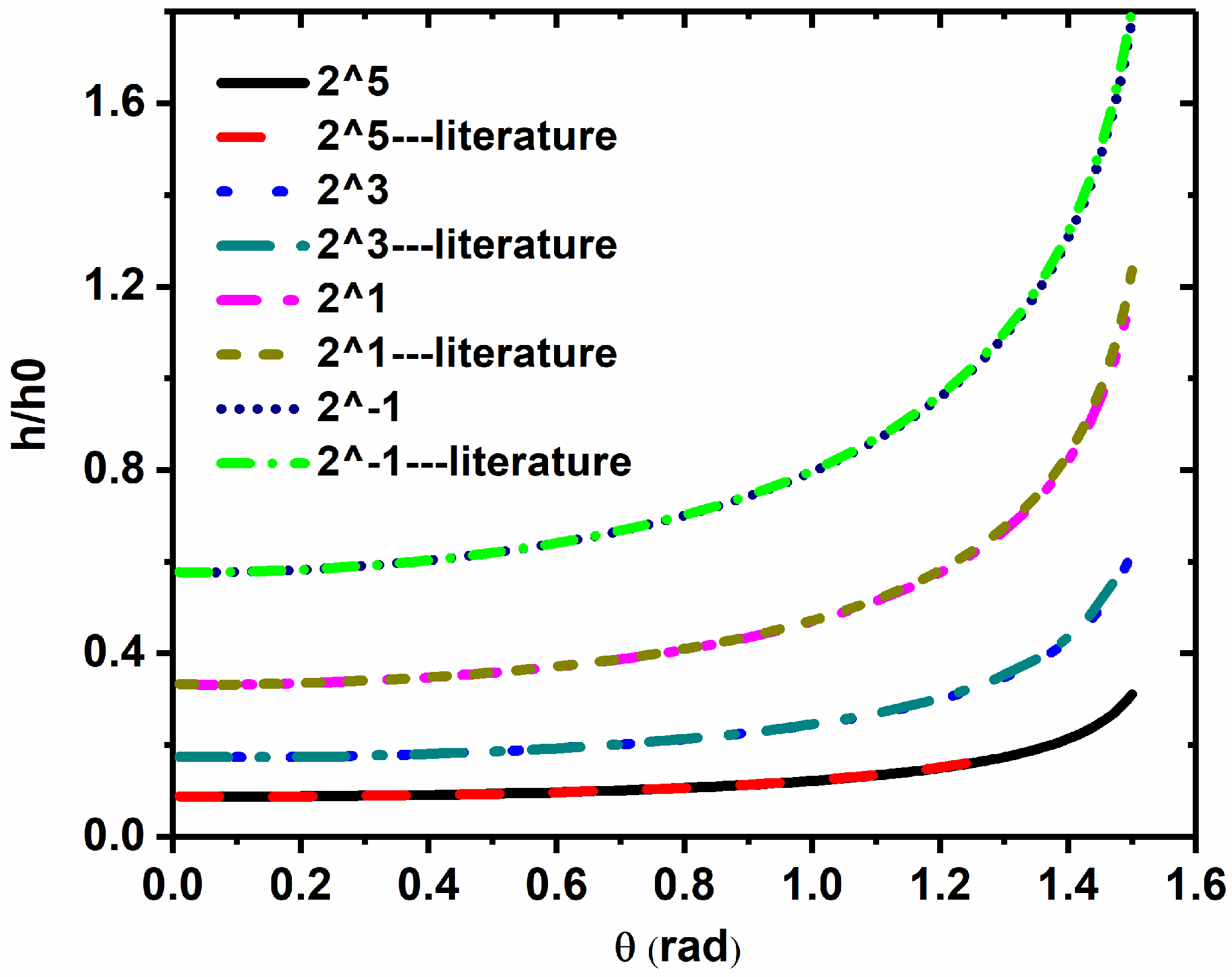
Figure 8.
Film thickness profile at different T with non-uniform initial film (h = h0sin θ).
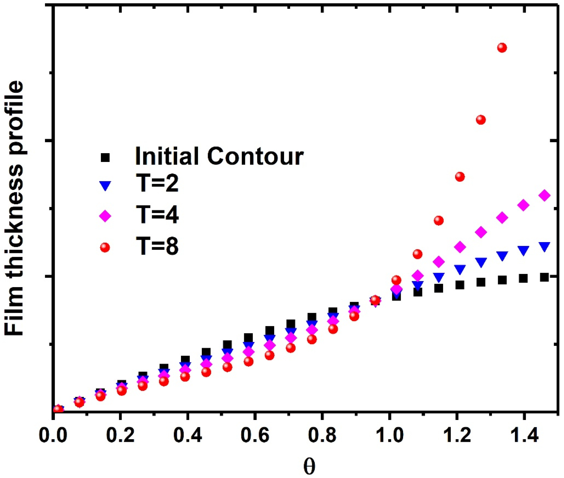
Figure 9.
Film thickness profile at different T with non-uniform initial film (h = h0cos θ).
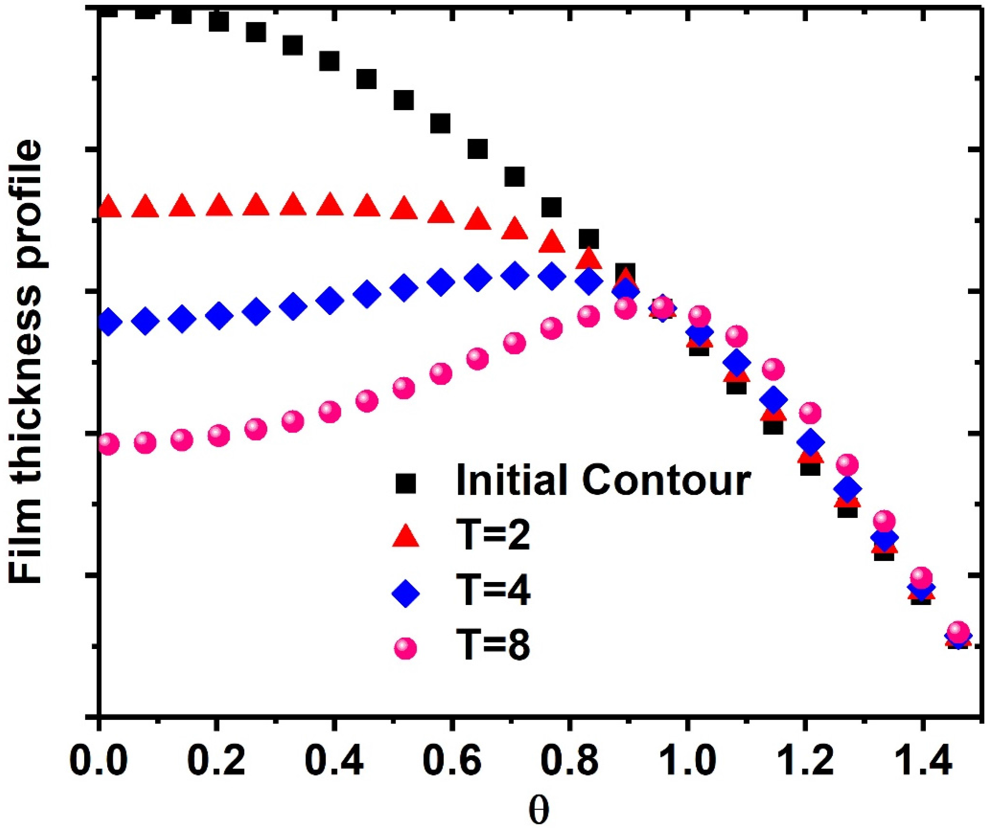
Figure 10.
Self-designed measurement system for film thickness distribution on spherical surface.

Figure 11.
Viscosity measurement of epoxy at 90 °C with parallel plate rheometry.
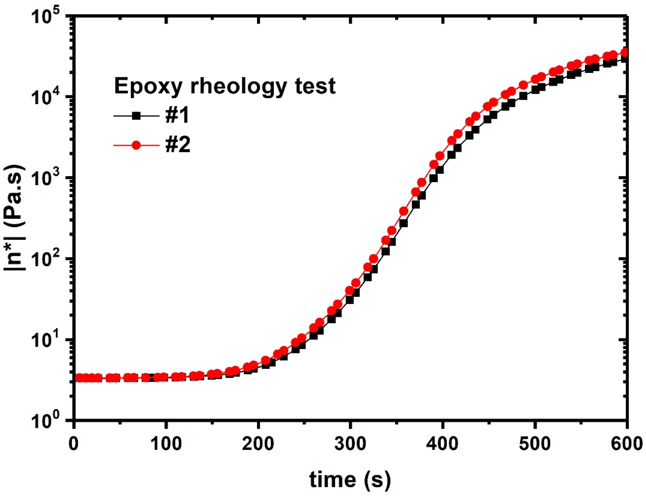
Figure 12.
Experimental and theoretical value of film thickness on a spherical surface by spin coating.
Figure 12.
Experimental and theoretical value of film thickness on a spherical surface by spin coating.

Table 1.
Uniformity of film thickness at different T.
| T | hmax/hmin |
|---|---|
| 26 | 2.8647 |
| 25 | 3.5315 |
| 24 | 3.5658 |
| 23 | 3.577 |
| 22 | 3.5849 |
| 21 | 3.5795 |
© 2017 by the authors. Licensee MDPI, Basel, Switzerland. This article is an open access article distributed under the terms and conditions of the Creative Commons Attribution (CC BY) license (http://creativecommons.org/licenses/by/4.0/).
Share and Cite
MDPI and ACS Style
Liu, H.; Fang, X.; Meng, L.; Wang, S. Spin Coating on Spherical Surface with Large Central Angles. Coatings 2017, 7, 124. https://doi.org/10.3390/coatings7080124
AMA Style
Liu H, Fang X, Meng L, Wang S. Spin Coating on Spherical Surface with Large Central Angles. Coatings. 2017; 7(8):124. https://doi.org/10.3390/coatings7080124
Chicago/Turabian StyleLiu, Huan, Xudong Fang, Le Meng, and Shanshan Wang. 2017. "Spin Coating on Spherical Surface with Large Central Angles" Coatings 7, no. 8: 124. https://doi.org/10.3390/coatings7080124
Note that from the first issue of 2016, this journal uses article numbers instead of page numbers. See further details here.