Characteristics of RF-Sputtered Thin Films of Calcium Phosphate on Titanium Dental Implants

1
Department of Mechanical Engineering, Ming Chi University of Technology, 84 Gung-juan Rd., Taishan Dist., New Taipei City 24301, Taiwan
2
Institute of Mechanical and Electrical Engineering, Ming Chi University of Technology, New Taipei City 24301, Taiwan
*
Author to whom correspondence should be addressed.
Coatings 2017, 7(8), 126; https://doi.org/10.3390/coatings7080126
Submission received: 30 June 2017
/
Revised: 14 August 2017
/
Accepted: 14 August 2017
/
Published: 16 August 2017
(This article belongs to the Special Issue Dental Implant Surface: Science and Technology)
Abstract
:Hydroxyapatite (HA) coatings on titanium have been investigated for many years, and have demonstrated advantageous biocompatibility in dental implants. Animal experiments have demonstrated that the biological response to plasma-sprayed HA-coated implants shows disadvantages in terms of adherence, thickness uniformity, and long-term osseointegration effects. Determining how to resolve the degradation problem of HA in the body by improving osseointegration and stability in alveolar bones has become an increasingly researched topic. The present study investigated the film characteristics and dissolution properties of calcium phosphate (CaP) coatings obtained by radio-frequency (RF) sputtering of a self-developed atmospheric plasma spray (APS) HA target. The experimental parameters varied, including RF power (60–250 W), sputtering time (15–120 min), and substrate roughness (0.4–4 μm). Analyses were conducted using synchrotron X-ray diffraction, Fourier transform infrared spectroscopy (FTIR), white light interferometry, and scanning electron microscopy combined with energy-dispersive X-ray spectroscopy (EDS). EDS analysis showed that the Ca/P ratio increased as the discharge power was increased. The analysis results also showed that a lower surface roughness resulted in higher crystallinity, because a larger surface-free energy was attained during sputtering. In-plane texturing has been proven when HA films are sputtered onto substrates of varying roughness, within appropriate deposition parameters. FTIR analysis revealed the presence of the principal PO43− bonds in the deposited calcium phosphate films. The CaP films induced calcium phosphate precipitation when immersed in simulated body fluid (SBF), suggesting that, based on in vitro bioactive behavior, the proposed combined surface modification can be used in dental implants.
1. Introduction
In recent years, the surface treatment of dental implants has rapidly developed. A common surface treatment involves sandblasting accompanied by acid etching (SLA) [1], creating numerous micropores on the implant surface to provide space for ingrowing bone tissue. This surface treatment method presents drawbacks as the SLA-treated implants require a long healing period of approximately three to six months. To accelerate healing, applying a plasma-sprayed coating of hydroxyapatite (HA, Ca10(PO4)6(OH)2) [2,3,4,5,6] to the implant surfaces can increase biocompatibility and induce rapid bone tissue ingrowth. HA is like the inorganic component of human bone tissue, thus exhibiting favorable bioactivity and osseointegration [4,5]. However, hydroxyapatite coatings may degrade when in contact with body fluids, resulting in poor long-term stability. An alternative technique for applying the coating is sputtering [7,8,9,10,11,12,13,14,15,16], which involves the dense and uniform deposition of nanoscale films. Sputtered HA shows high adhesive strength to the substrate [12]. Combining the sputtering technique with HA and SLA surface treatments can promote the biocompatibility and stability of dental implants. Although HA sputter targets are commercially available, the authors previously developed an atmospheric plasma-sprayed (APS) HA target [17] that can be used to perform sputtering processes [18].
Resolving the dissolution problem of HA in simulated bodily fluid (SBF) to improve osseointegration and stability in alveolar bones has become a frequently researched topic; therefore, this study investigated the film characteristics of HA coatings obtained using radio frequency (RF) sputtering. The substrate mainly involved using titanium treated in an SLA-like process; however, grinding and sandblasting treatments were simultaneously used to create different surface roughnesses and to investigate the effects of HA films on the substrates. Finally, a 4-week-long in vitro test was conducted to determine the dissolution properties of HA film on SLA-like Ti.
2. Materials and Experimental Methods
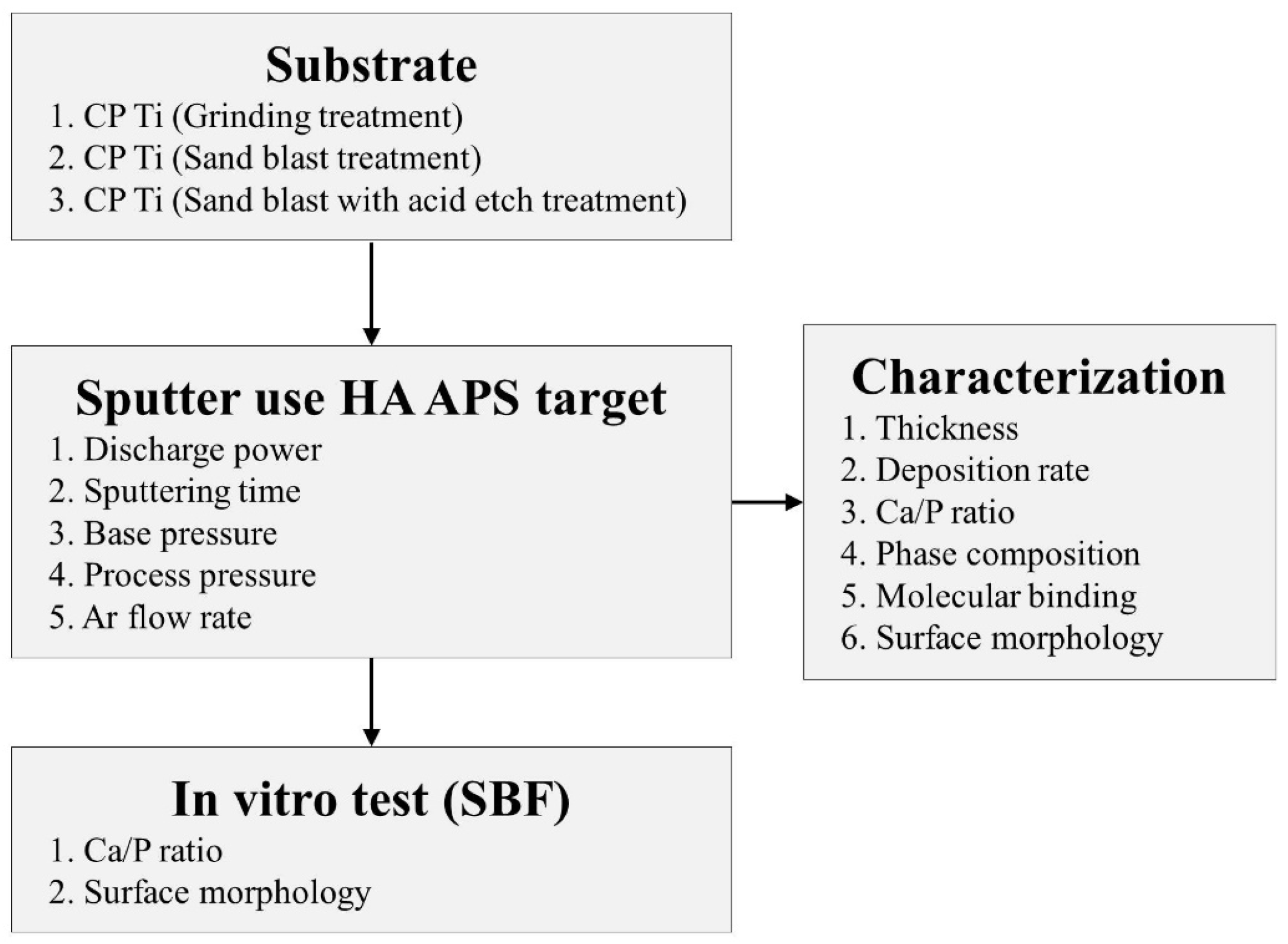
Figure 1 shows the flowchart of this study. First, the properties of the as-sputtered HA films on CP-Ti grade IV (Daido Steel Co., Ltd., Nagoya, Japan) plates—each treated differently using grinding, sandblasting, and SLA-like treatments—were analyzed. Parameters of different Ti substrates used in this paper was shown in Table 1. The RF-sputtering equipment was manufactured by Kao-Duen (R25A08, New Taipei City, Taiwan), the HA sputter target of 50.8 mm diameter and 2 mm thickness was fabricated using an in-lab APS technique (Figure 1). All HA film samples were deposited onto different CP-Ti plates (9.6 mm in diameter and 2 mm in thickness), as mentioned, using RF sputtering at a discharge power of 60–250 W (run at set processing parameters listed in Table 2). The roughness of the Ti plate was analyzed using white-light interferometry (Chroma 7502, New Taipei City, Taiwan). The as-sputtered HA films were characterized according to film thickness and surface morphology (field emission scanning electron microscope, FE-SEM, JSM-6701F, JEOL, Tokyo, Japan), the Ca/P ratio (energy-dispersive X-ray spectroscope, EDS, S—3400N, HITACHI, Tokyo, Japan), phase composition (X-ray diffractometer, XRD, X’Pert Pro, PHILIPS, Eindhoven, The Netherlands; Cu-Kα Cu-K P Å, 40 kV, 30 mA, scan speed 0.1 s/step), and chemical composition (Fourier transform infrared spectroscope, FTIR, One FT-IR, Perkin Elmer, Waltham, MA, USA; frequency range 4000–400 cm−1, resolution 8 cm−1). The in vitro test was performed by immersing the HA-coated Ti plate with an SLA-like surface in the SBF for 4 weeks. The Ca/P ratio was then analyzed, and the surface appearance was observed after immersion. Finally, the dissolution properties of sputtered HA in SBF (SIGMA H8264, Hanks’ Balanced Salt Solution, Saint Louis, MO, USA) were determined to obtain an appropriate protocol for sputtered HA coatings on SLA-like implant surfaces. The dissolution experiments were started as: tubes were cleaned by ultrasonic cleaner with alcohol for 1 hour and dried. Then, specimens and test tube were put in the environment at 120 °C for 8 h and UV irradiated for 1 hour for sanitizing. Simulated body fluid was put into a test tube with pipette to fix the volume of SBF (the volume was calculated by the HA coating area of the specimen: 30 mL SBF per cm2 of HA area). The specimens were then immersed into SBF and the tube placed into the CO2 incubator (5% CO2, 37 °C) to start the in vitro test. The reaction response over different time periods (7, 14, 21, and 28 days) was observed. The fluid sampling then proceeded to inductively coupled plasma optical emission spectrometry (ICP-OES, Optima 2100DV, Perkin Elmer, Waltham, MA, USA) analysis to inspect the dissolving phenomenon caused by the sputtered CaP thin-film.
3. Results and Discussion
3.1. Characterization of Sputtered CaP Coatings on Different Substrates
3.1.1. Substrate Roughness
First, the roughness of the Ti substrates was analyzed after treatment by grinding, sandblasting, or sandblasting accompanied by SLA-like acid etching. The white-light interferometry images of the Ti plates shown in Figure 2 indicate that the surface roughness (scan area: 730 μm × 730 μm) of the ground substrate was 0.4 μm, that of the sandblasted substrate was 4.0 μm, and that of the sandblasted and acid etched substrate was 2.4 μm. Since strong acid etching damages high or sharp structures, the surface of the SLA-like substrate had a lower roughness than that of the sandblasted substrate. The grinding process was applied to improve the appearance of the substrate surface; thus, the ground substrate exhibited a lower surface roughness compared to the other two substrates.
3.1.2. Thickness Analysis of HA-Sputtered Films
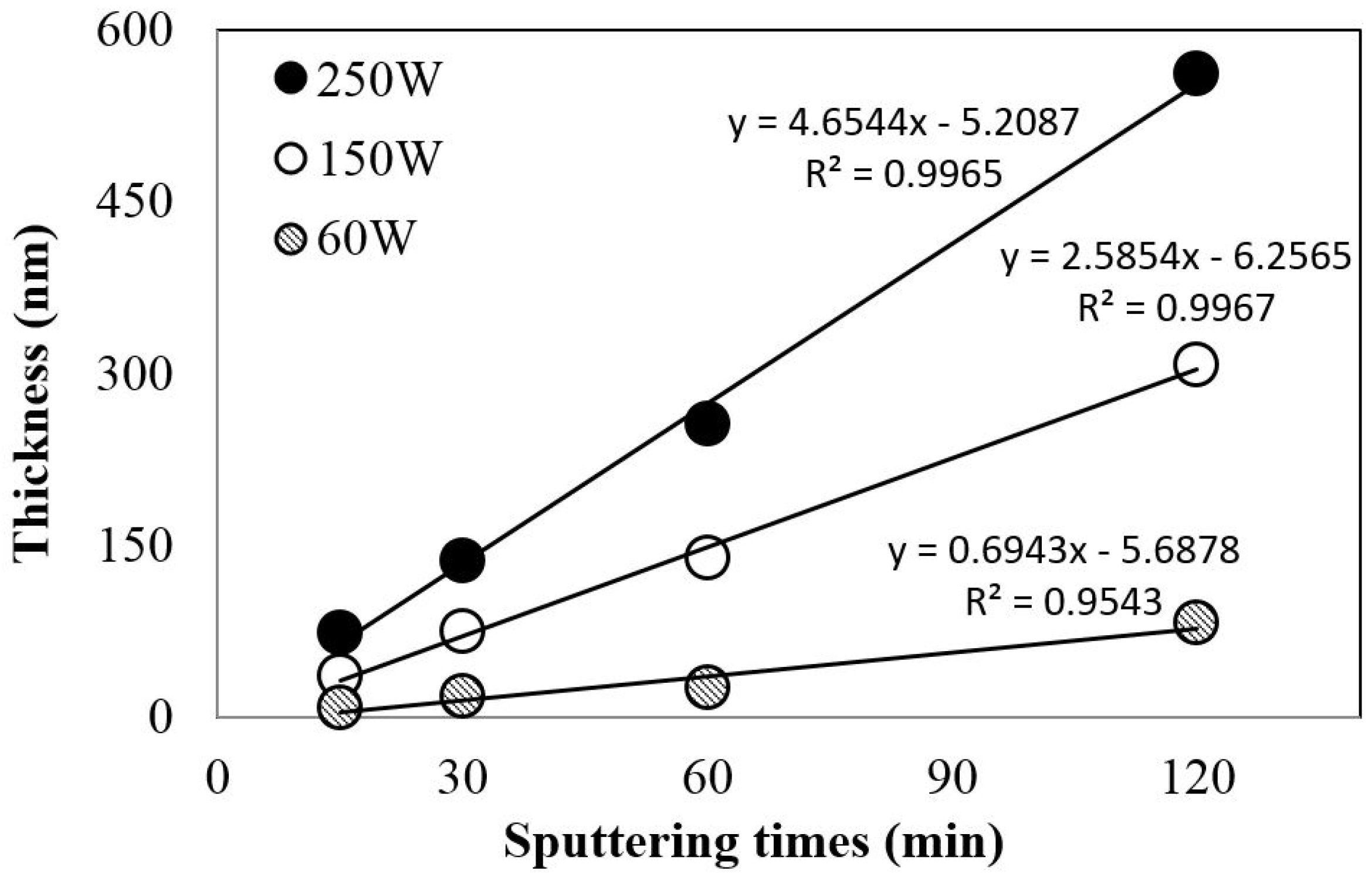
Figure 3 depicts the relationship between HA film thickness, discharge power, and sputtering time. The thickness increased linearly as the sputtering time increased from 15 to 120 min, and accordingly, the deposition rates of the HA films varied at different power levels. Figure 3 shows the deposition rates of 4.65, 2.58 and 0.69 nm/min when the power levels were 250, 150 and 60 W, respectively. Higher power might induce larger sputtering yields, resulting in higher deposition rates. Compared to the plasma sprayed coating technology, the deposition rate of the sputter technology is lower; thus, the plasma spray technology is generally used for the hip coating and sputtering coating technology is generally more suitable for the dental implant or fusion cage.
3.1.3. Ca/P Ratio of HA-Sputtered Films
Figure 4 shows the Ca/P ratio of films deposited at different power levels on various substrates. The sputtering time is constant at 120 min. As shown, CaP films on substrates with different roughness do not affect the Ca/P ratio. The Ca/P ratio increased from 1.6 to 2.14 as the power level increased from 60 to 250 W. The atomic energy increased with sputtering discharge power. Moreover, at high energy, the phosphate atoms desorbed easily and mainly returned to the working gas, thus leading to an increased Ca/P ratio. It should be noted that only low energy discharge power led to close-to-stoichiometric HA films (Ca/P ratio of HA is 1.67).
3.1.4. Phase and Chemical Compositions of CaP Films
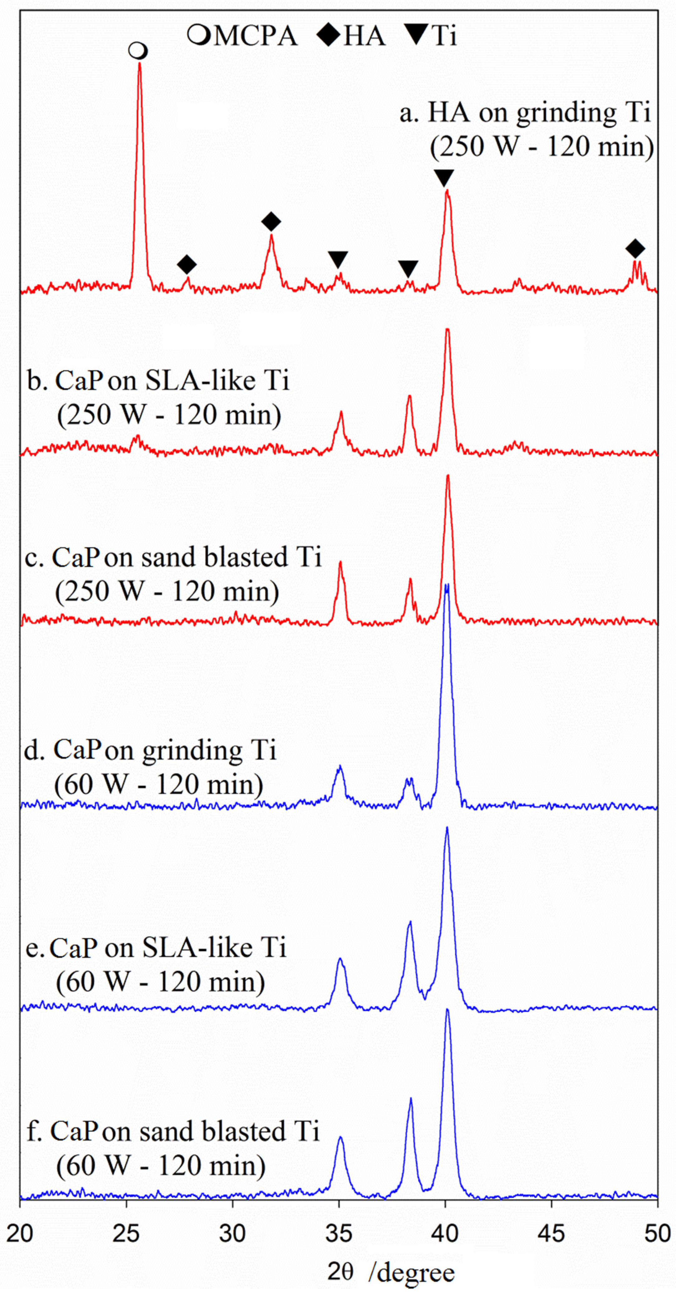
After the phase composition was identified using XRD (Figure 5), only the CaP films on the lower-roughness substrates revealed HA and monocalcium phosphate anhydrate (MCPA) at the sputtering discharge power level of 250 W after 120 min, whereas the higher-roughness substrates did not show any HA crystalline phase. The HA clusters deposited on the smoother surface of the ground substrate were larger and exhibited larger surface-free energy for enhancing crystallinity due to a smaller contact angle between the film and substrate. Therefore, the roughness of different substrates exhibited different levels of surface-free energy during the HA sputtering process. The concept coincides with the theory of thin-film deposition on semiconductor processes. Furthermore, the deposition times provided the reaction energy for forming the crystalline phases of the HA films.
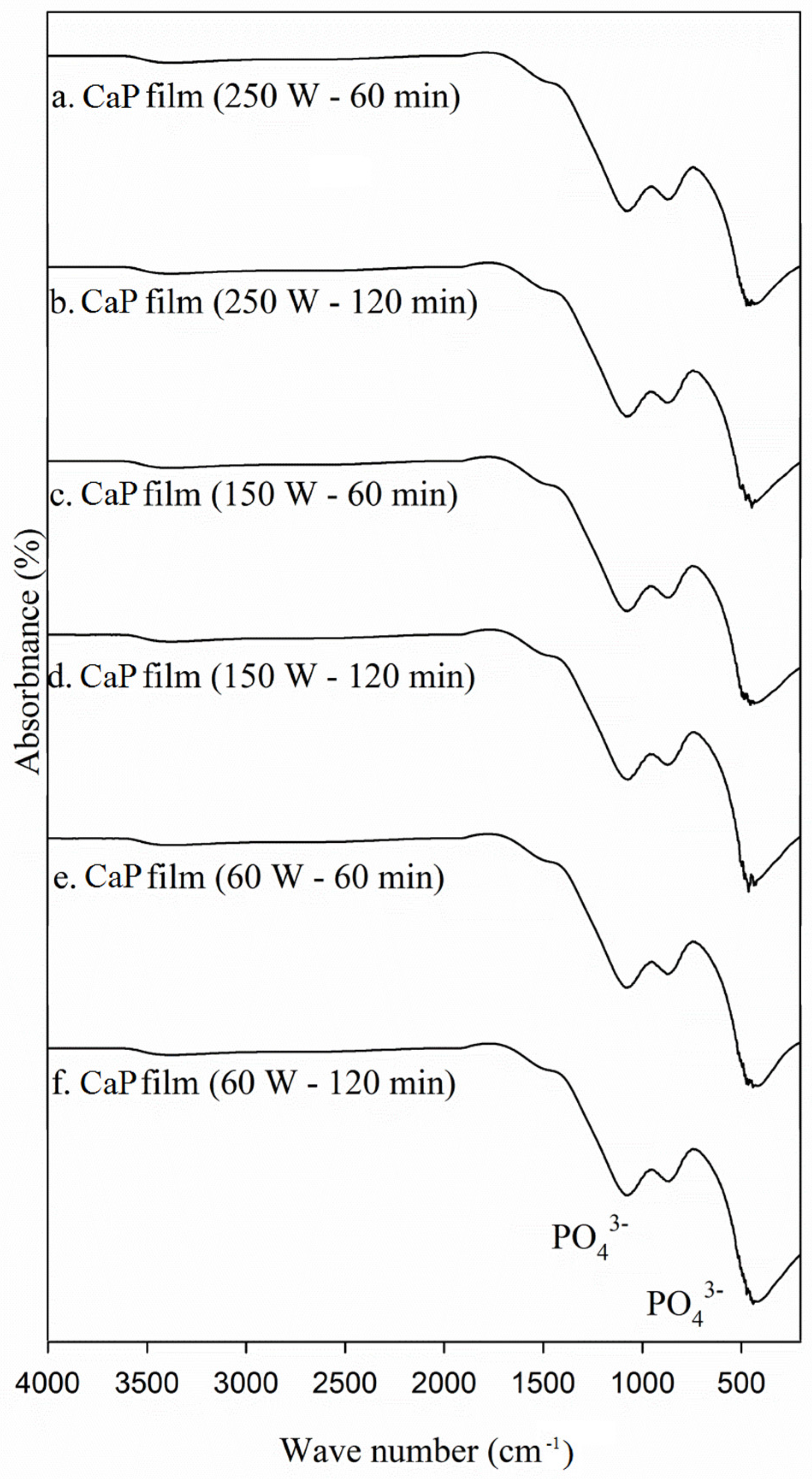
Based on the aforementioned principles, Figure 5 shows that the HA and MCPA crystalline phases appeared only at high power and during long sputtering times. The chemical composition of the HA film was analyzed using FTIR (Figure 6), the results of which showed that bands existed, but the OH− was nearly absent in the as-sputtered HA films. This may have been due to the sputtering environment being in a high vacuum; the Ca and P atoms could have deposited onto the substrate, but the OH− would have been easily removed by the working gas. There is a wide band in the range 1100–967 cm−1 which shows that there is a great amount of basic phosphates. However, we still do not know exactly how much influence biological activity had if OH− in HA film was lost. Theoretically, the phosphate contained in CaP should be a more important composition because CaP is in contact with the organism. Calcium phosphate thin-film will produce degradation or deposition reaction in body fluids, and then change the pH value, will easily react with calcium phosphate ions in body fluids, and segregation of apatite phase (Apatite), and then, when the calcium ion and phosphorus ion concentration reach the saturated concentration of HA, it will generate an HA phase to enhance its biological activity. In contrast to the Ca/P ratio, although the phase composition exhibited multiple CaP phases, the MCPA and amorphous phases and the analyzed Ca/P ratio revealed only the macrocosm of sputtered films, in that the sputtered films had Ca/P ratios of 1.6–2.14 from 60 W to 250 W.
3.1.5. Surface Morphology Analysis of CaP Films
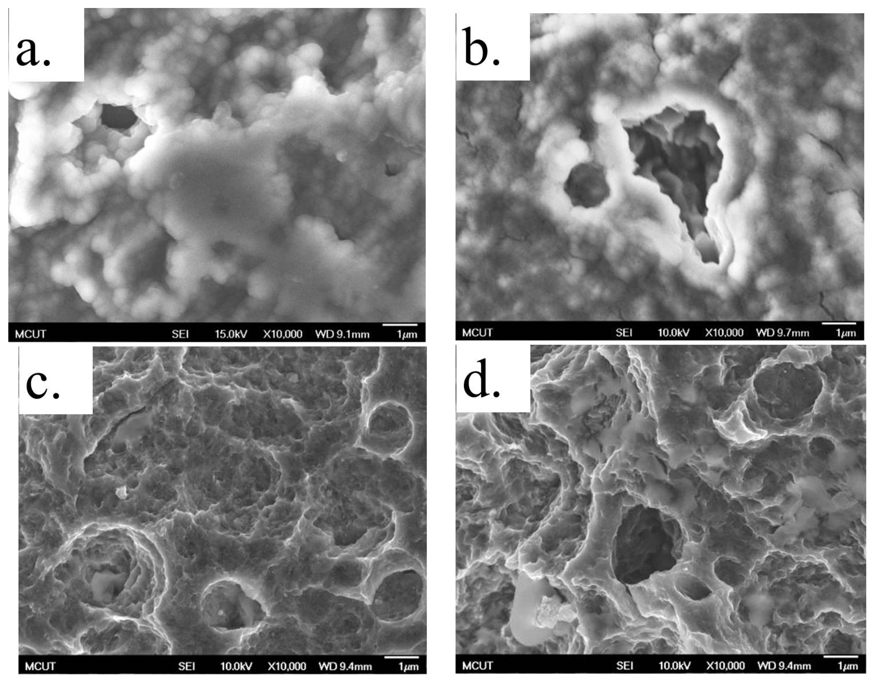
The surface morphology of different substrates undergoing sputtering for 120 min were observed using FE-SEM. Figure 7a shows the image of a substrate that underwent SLA-like treatment, showing uniform µm–nm-sized holes at the surface. Figure 7b–d show images of a substrate that underwent the combined (SLA-like and HA sputtering) treatment at 60 W (approximately 83 nm in thickness), 150 W (approximately 310 nm in thickness), and 250 W (approximately 558 nm in thickness), respectively. These results demonstrate that the film thickness increases with increasing sputtering power when the sputtering time is constant. Moreover, the thin CaP films were deposited more easily on the substrate with a higher surface area when the sputtering power is higher, thus leading to a cumulative effect of CaP thin film on µm–nm holes of the original SLA-like surface. In Figure 7b–d, compared to Figure 7a, it was found that the surface in Figure 7c could retain the µm shape of the SLA-like holes. It would be helpful for osteoblast to be attached to it. To maintain the morphology of µm–nm holes on a substrate, the coating film fabricated at 150 W and 120 min enables the surface morphology to be maintained.
3.2. Dissolution Assay
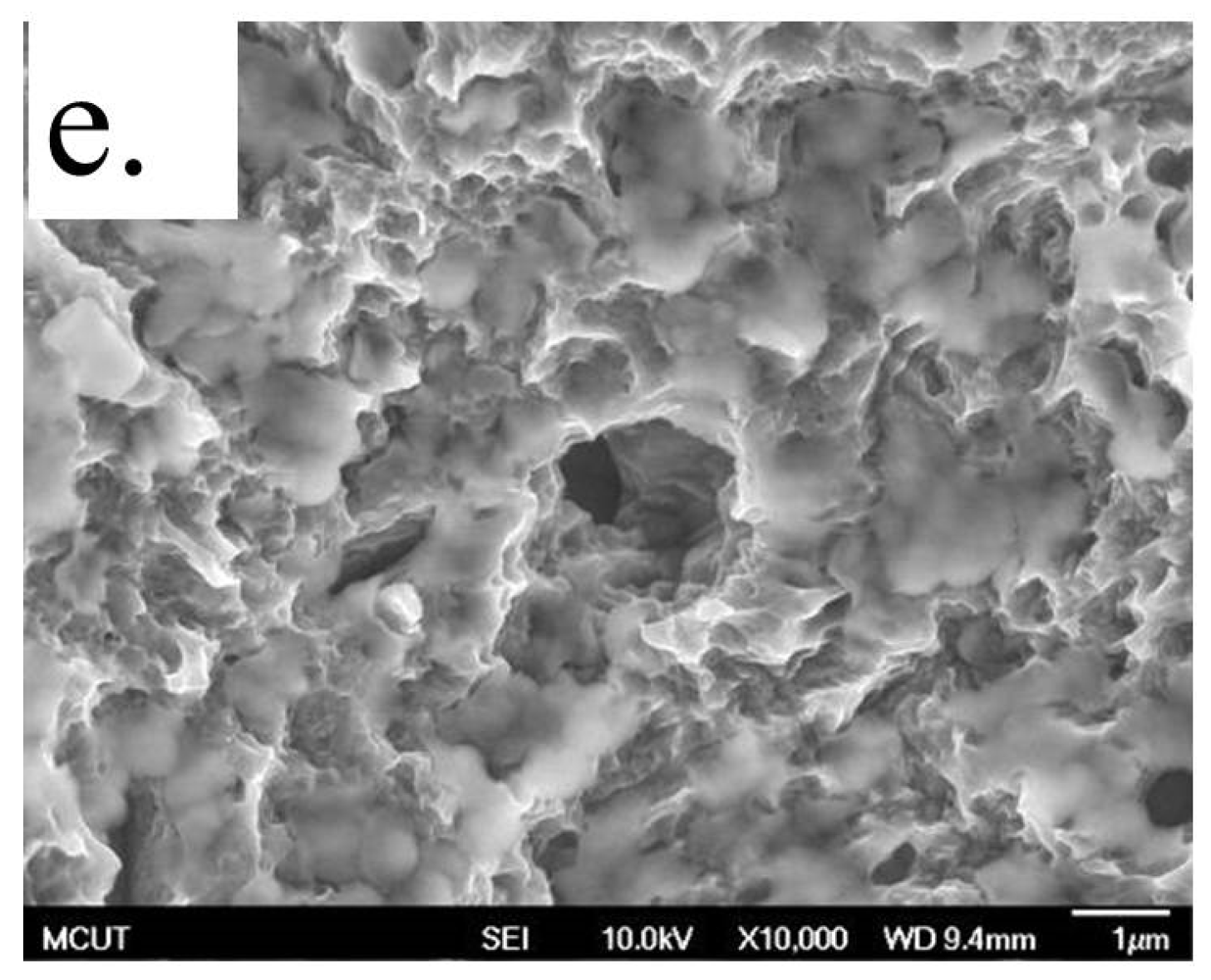
In the in vitro test, CaP films (250 W, 120 min) were sputtered onto a Ti surface treated using an SLA-like process and immersed in SBF for 4 weeks. The essential function of an SBF is to maintain pH (roughly 7.0–7.4) and osmotic balance as well as provide cells with water and essential inorganic ions in in vitro experiments. Hanks’ Salts is a collective group of salts rich in bicarbonate ions, formulated in 1940 by the microbiologist John H. Hanks. Figure 8 shows that the Ca/P ratio decreased to a theoretical ratio of HA at 1.67 after 28 days of immersion. The concentration of calcium and phosphorus ions in the remaining SBF was removed. Theoretically, the two reaction rates of dissolution and deposition of the CaP coating were in comparison with the ICP-OES. At 0–14 days, the calcium and phosphorus ions in SBF began to increase, indicating that the degradation rate of this stage was greater than the deposition. After seven days, the calcium content in SBF began to reduce first, indicating that the degradation of the calcium concentration at this time had reached saturation. It then began to significantly deposit back to the titanium plate. After 14 days, the degradation of phosphorus ion concentration also reached saturation and began to clearly form a bond with calcium ions. Segregation of the apatite phase and the bone-like calcium phosphate was continuously deposited until 28 days. Compared with SLA-like titanium plates with HA coating, as shown in Figure 9a, the calcium and phosphorus content on the surface were reduced after 0 to 14 days of immersion (Figure 9b,c), indicating that calcium phosphate was degraded into SBF. This result also echoes Figure 9b,c. After soaking the SBF for 28 days, it can be seen clearly on the titanium plate surface that there were new deposits in reaction to calcium and phosphorus (Figure 9d,e). In contrast to the observed surface appearance of the immersed SLA-like Ti with HA films (Figure 9), the HA film dissolved during the first 7 days; it then induced calcium phosphate precipitation when immersed in SBF after 14 to 28 days (Figure 9d,e). In this study, we have tried to measure the thickness change after immersing specimens in SBF. However, the Ti surface structure after surface treatment is porous. The surface roughness is about 2.4–4 µm, so the thickness change of the thin-film is difficult to measure accurately. Besides, large fluctuation of the Ti specimens’ surface also increased the difficulty of the scratch test by nano-indenter. So, we are currently unable to measure the contact force of the new CaP material with the substrate.
4. Conclusion
This study investigated the characteristics of CaP films obtained by sputtering from an HA target on Ti substrates exhibiting different surface coarseness. The experimental results of this study suggest that the CaP films had a deposition rate of 4.65 nm/min for a sputtering power of 250 W and a Ca/P ratio of 1.6–2.14 for a power of 60–250 W. This study proved that CaP films induce calcium phosphate precipitation after 14 to 28 days when immersed in SBF, suggesting that, based on in vitro bioactive behavior, the proposed combined surface modification could be used in dental implants.
Acknowledgments
Part of this study was conducted by industry-university cooperative research with Chang Gung Medical (CGM) Technology Co., Ltd., Taipei City, Taiwan. The authors would like to thank CGM for their support with manpower, equipment, and expenditure, which facilitated the smooth progress of the work.
Author Contributions
K.-Y. Hung and H.-P. Feng conceived and designed the experiments; H.-C. Lai performed the experimentsand analyzed the data; K.-Y. Hung and H.-P. Feng wrote the paper.
Conflicts of Interest
The authors declare no conflict of interest.
References
- Ferguson, S.J.; Broggini, N.; Wieland, M.; Wild, M.D.; Rupp, F.; Geis-Gerstorfer, J.; Cochran, D.L.; Buser, D. Biomechanical evaluation of the interfacial strength of a chemically modified sandblasted and acid-etched titanium surface. J. Biomed. Mater. Res. Part A 2006, 24, 291–297. [Google Scholar] [CrossRef] [PubMed]
- Cizek, J.; Khor, K.A.; Prochazka, Z. Influence of spraying conditions on thermal and velocity properties of plasma sprayed hydroxyapatite. Mater. Sci. Eng. C 2007, 27, 340–344. [Google Scholar] [CrossRef]
- Sun, L.; Berndt, C.C.; Grey, C.P. Phase, structural and microstructural investigations of plasma sprayed hydroxyapatite coatings. Mater. Sci. Eng. A 2003, 360, 70–84. [Google Scholar] [CrossRef]
- Aoki, H. Marvelous Biomaterial Apatite; Ishiyaku Publishers Inc.: Tokyo, Japan, 1999. [Google Scholar]
- Ravaglioli, A.; Krajewski, A. Bioceramics: Materials, Properties, Applications; Chapman & Hall Press: London, UK, 1992; pp. 44–45. [Google Scholar]
- Yang, Y. Influence of residual stress on bonding strength of plasma-sprayed hydroxyapatite coatings on Ti6Al4V substrate. Ph.D. Thesis, National Cheng Kung University, Tainan, Taiwan, 27 June 2003. [Google Scholar]
- Mercioniu, I.; Ciuca, S.; Pasuk, I.; Slav, A.; Morosnu, C.; Bercu, M. Thickness dependence of crystallization process for hydroxyapatite thin films. J. Optoelectron. Adv. Mater. 2007, 9, 2535–2538. [Google Scholar]
- Wolke, J.G.C.; Dijk, K.V.; Schaeken, H.G.; Groot, K.D.; Jansen, J.A. Study of the surface characteristics of magnetron-sputter calcium phosphate coatings. J. Biomed. Mater. Res. 1994, 28, 1477–1484. [Google Scholar] [CrossRef] [PubMed]
- Dijk, K.V.; Schaeken, H.G.; Wolke, J.G.C.; Maree, C.H.M.F.; Habraken, H.P.M.; Verhoven, J.; Jansen, J.A. Influence of discharge power level on the properties of hydroxyapatite films deposited on Ti6Al4V with RF magnetron sputtering. J. Biomed. Mater. Res. 1995, 29, 269–276. [Google Scholar] [CrossRef] [PubMed]
- Dijk, K.V.; Schaeken, H.G.; Wolke, J.G.C.; Jansen, J.A. Influence of annealing temperature on RF-magnetron sputtered calcium phosphate coatings. Biomaterials 1996, 17, 405–410. [Google Scholar] [PubMed]
- De Groot, K.; Klein, C.P.A.T.; Wolke, J.G.C.; Blieck-Hoger-vorst, J.M.A.D. Chemistry of calcium phosphate bioceramics. In CRC Handbook of Bioactive Ceramics. II Calcium Phosphate and Hydroxylapatite Ceramics; Yamamuro, T., Hench, L.L., Wilson, J., Eds.; CRC Press Inc.: Boca Raton, FL, USA, 1990; pp. 3–16. [Google Scholar]
- Wan, T.; Aoki, H.; Hikawa, J.; Lee, J.H. RF-magnetron sputtering technique for producing hydroxyapatite coating film on various substrates. Bio-Med. Mater. Eng. 2007, 17, 291–297. [Google Scholar]
- Wolke, J.G.C.; Groot, K.D.; Jansen, J.A. In vivo dissolution behavior of various RF magnetron sputtered Ca-P coatings. J. Biomed. Mater. Res. 1998, 39, 524–530. [Google Scholar] [CrossRef]
- Wolke, J.G.C.; Waerden, V.D.; Schaeken, H.G.; Jansen, J.A. In vivo dissolution behavior of various RF magnetron-sputtered Ca-P coatings on roughened titanium implants. Biomaterials 2003, 24, 2623–2629. [Google Scholar] [CrossRef]
- Chen, J.; Wolke, J.G.C.; Groot, K.D. Microstructure and crystallinity in hydroxyapatite coatings. Biomaterials 1994, 15, 396–399. [Google Scholar] [CrossRef]
- Dijk, K.V.; Schaeken, H.G.; Wolke, J.G.C.; Jansen, J.A. Influence of annealing temperature on RF magnetron sputtered calcium phosphate coatings. Biomaterials 1996, 17, 405–410. [Google Scholar] [PubMed]
- Lai, H.-C.; Tsai, H.-H.; Hung, K.-Y.; Feng, H.-P. Fabrication of hydroxyapatite targets in RF-sputtering for surface modification of titanium dental implants. J. Intell. Mater. Syst. Struct. 2015, 26, 1050–1058. [Google Scholar] [CrossRef]
- Hung, K.-Y.; Lo, S.-C.; Shih, C.-S.; Yang, Y.-C.; Feng, H.-P.; Lin, Y.-C. Titanium surface modified by hydroxyapatite coating for dental implants. Surf. Coat. Technol. 2013, 231, 337–345. [Google Scholar] [CrossRef]
Figure 1.
Flowchart of this study (Ar flow rate means argon flow rate during the sputtering process). APS: atmospheric plasma-sprayed; HA: hydroxyapatite; SBF: simulated body fluid.
Figure 1.
Flowchart of this study (Ar flow rate means argon flow rate during the sputtering process). APS: atmospheric plasma-sprayed; HA: hydroxyapatite; SBF: simulated body fluid.

Figure 2.
Surface roughness of different Ti substrates measured by white light interferometry imaging: (a) Substrate treated by grinding; (b) Substrate treated by sandblasting; (c) Substrate treated by SLA-like treatment. (Scan area: 730 μm × 730 μm).
Figure 2.
Surface roughness of different Ti substrates measured by white light interferometry imaging: (a) Substrate treated by grinding; (b) Substrate treated by sandblasting; (c) Substrate treated by SLA-like treatment. (Scan area: 730 μm × 730 μm).
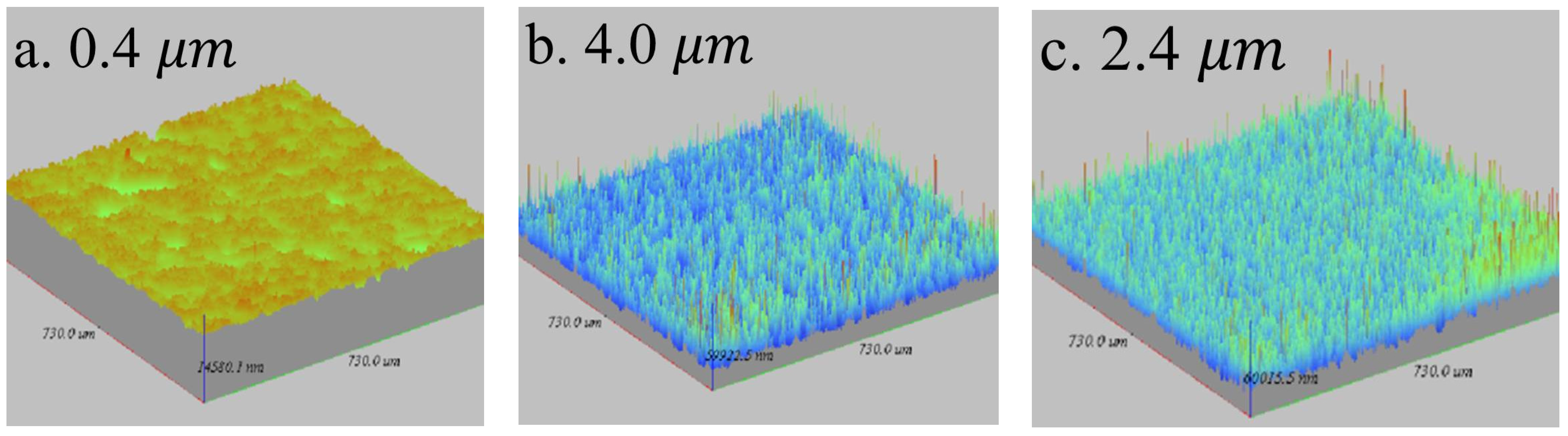
Figure 3.
Dependence of HA film thickness on discharge power and sputtering time.

Figure 4.
Ca/P ratio analysis of as-sputtered CaP films.
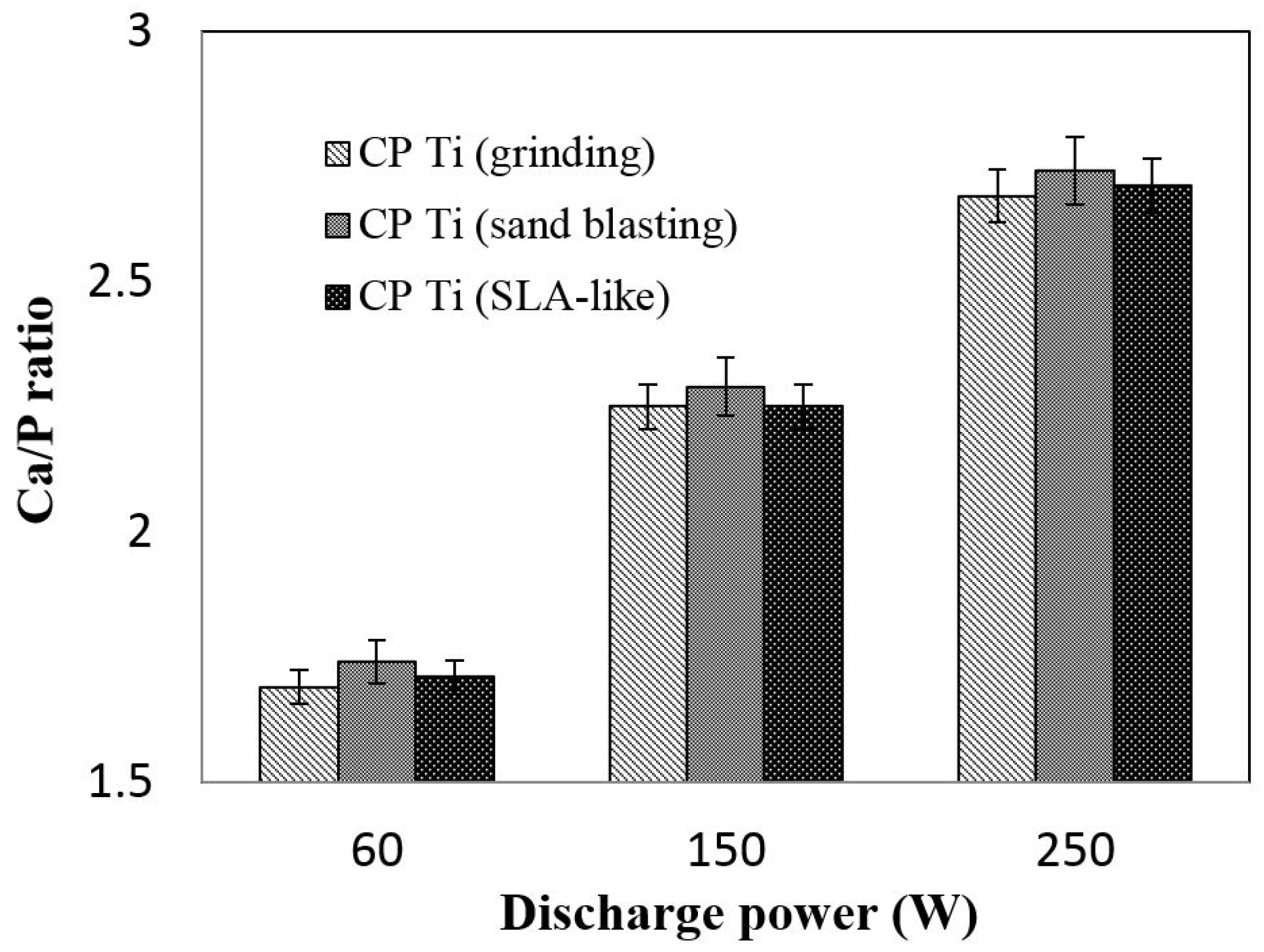
Figure 5.
XRD patterns of as-sputtered CaP films. MCPA: monocalcium phosphate anhydrate.

Figure 6.
Fourier transform infrared (FTIR) spectra of as-sputtered CaP films.

Figure 7.
Field emission scanning electron microscope (FE-SEM) micrographs of (a) SLA-like treated Ti; (b) HA film (60 W–120 min) on SLA-like treated Ti; (c) HA film (150 W–120 min) on SLA-like treated Ti; (d) HA film (250 W–120 min) on SLA-like treated Ti.
Figure 7.
Field emission scanning electron microscope (FE-SEM) micrographs of (a) SLA-like treated Ti; (b) HA film (60 W–120 min) on SLA-like treated Ti; (c) HA film (150 W–120 min) on SLA-like treated Ti; (d) HA film (250 W–120 min) on SLA-like treated Ti.
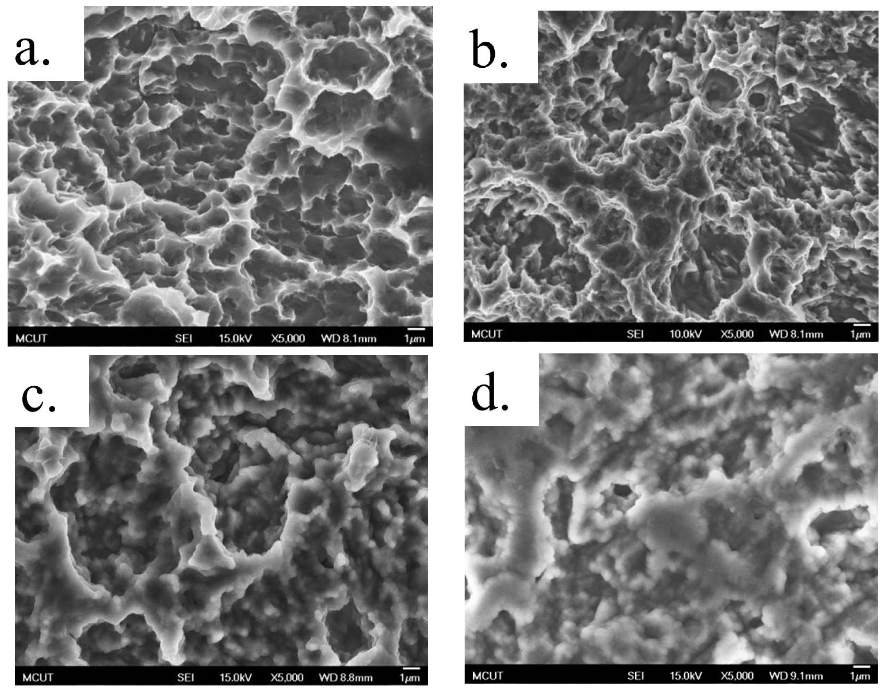
Figure 8.
Change of the Ca/P ratio of CaP films sputtered onto SLA-like Ti after immersion for 4 weeks in SBF.
Figure 8.
Change of the Ca/P ratio of CaP films sputtered onto SLA-like Ti after immersion for 4 weeks in SBF.
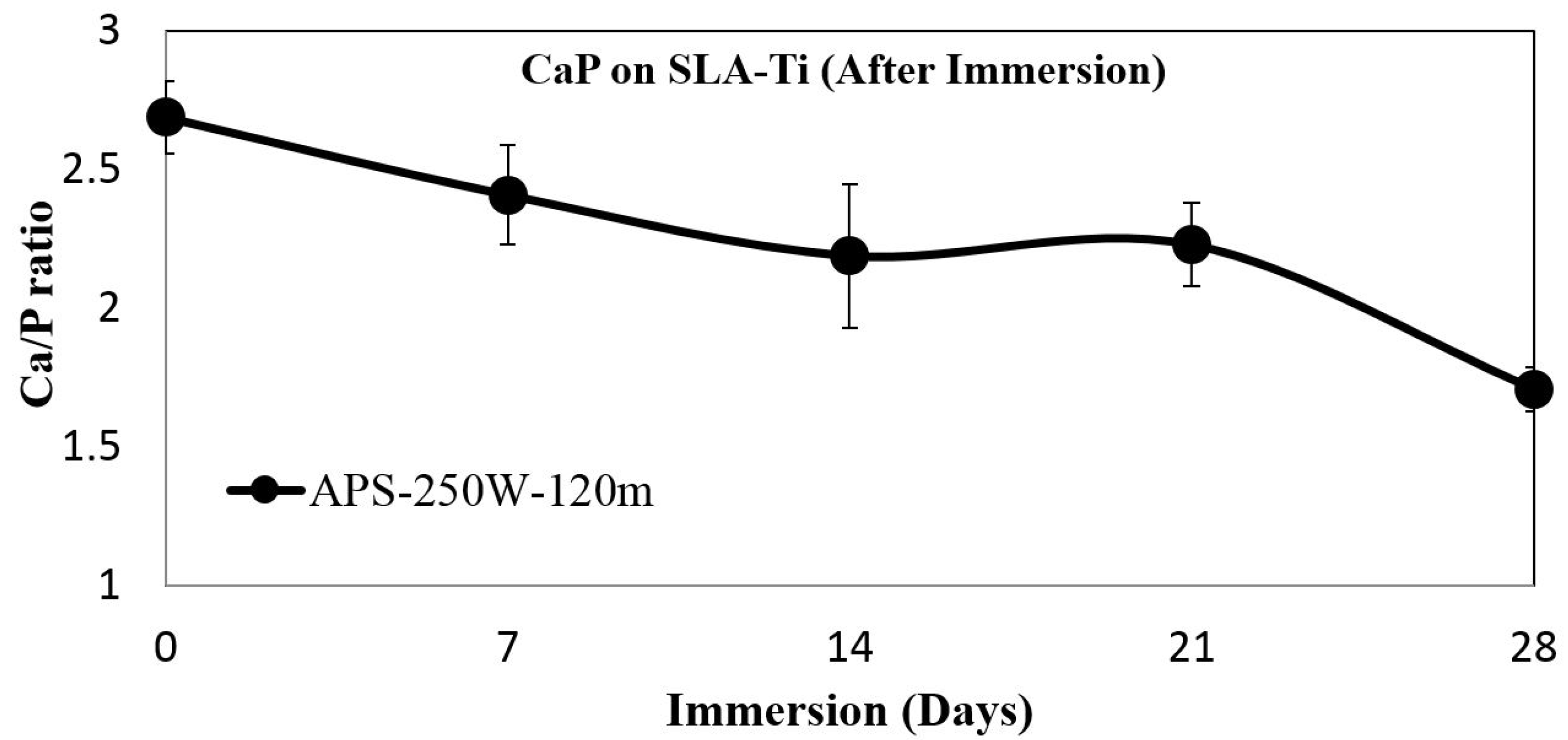
Figure 9.
FE-SEM micrographs of CaP film onto SLA-like Ti after immersion in SBF for 4 weeks: (a) 0, (b) 7, (c) 14, (d) 21 and (e) 28 days.
Figure 9.
FE-SEM micrographs of CaP film onto SLA-like Ti after immersion in SBF for 4 weeks: (a) 0, (b) 7, (c) 14, (d) 21 and (e) 28 days.


Table 1.
Parameters of different Ti substrates used in this paper.
| Substrate Type | Parameters of the Substrate Process |
|---|---|
| Grinding | Grinding Ti substrate by SiC Waterproof abrasive paper, #800 for 30 min and #1200 for 15 min |
| Sand blasting | Al2O3 (Grit No. 100), pressure at 4 kg/cm2 for 60 s |
| SLA-like (Sand blasting with acid etching) | Sand blasting, then acid etching by heated HCl (80 °C) and heated H2SO4 (120 °C), each for 600 s |
Table 2.
Sputtering process parameters.
| Parameters | Values |
|---|---|
| Sputtering time | 15–120 min |
| Base pressure | 0.9999177 × 10⁻³ Pa |
| Process pressure | 0.3999670 Pa |
| Argon flow rate | 20 sccm |
| Working distance | 70 mm |
| Power | 60–250 W |
© 2017 by the authors. Licensee MDPI, Basel, Switzerland. This article is an open access article distributed under the terms and conditions of the Creative Commons Attribution (CC BY) license (http://creativecommons.org/licenses/by/4.0/).
Share and Cite
MDPI and ACS Style
Hung, K.-Y.; Lai, H.-C.; Feng, H.-P. Characteristics of RF-Sputtered Thin Films of Calcium Phosphate on Titanium Dental Implants. Coatings 2017, 7, 126. https://doi.org/10.3390/coatings7080126
AMA Style
Hung K-Y, Lai H-C, Feng H-P. Characteristics of RF-Sputtered Thin Films of Calcium Phosphate on Titanium Dental Implants. Coatings. 2017; 7(8):126. https://doi.org/10.3390/coatings7080126
Chicago/Turabian StyleHung, Kuo-Yung, Hong-Chen Lai, and Hui-Ping Feng. 2017. "Characteristics of RF-Sputtered Thin Films of Calcium Phosphate on Titanium Dental Implants" Coatings 7, no. 8: 126. https://doi.org/10.3390/coatings7080126
Note that from the first issue of 2016, this journal uses article numbers instead of page numbers. See further details here.