Article

Zircon-Based Ceramic Coatings Formed by a New Multi-Chamber Gas-Dynamic Accelerator

1
Joint Research Center “Technology and Materials”, Belgorod State National Research University, Pobeda 85, Belgorod 308015, Russia
2
E.O. Paton Electric Welding Institute, NASU, Bozhenko 11, Kyiv 03650, Ukraine
3
Center for High Technologies, Belgorod State Technological University named after V.G. Shoukhov, Kostyukov 46, Belgorod 308012, Russia
*
Author to whom correspondence should be addressed.
Coatings 2017, 7(9), 142; https://doi.org/10.3390/coatings7090142
Submission received: 26 July 2017 / Revised: 4 September 2017 / Accepted: 5 September 2017 / Published: 8 September 2017

Abstract

:
In this work, dense zircon-based ceramic coatings were obtained from inexpensive zircon powder on a steel substrate by using a new multi-chamber gas-dynamic accelerator. The microstructure and phase composition of the coating were characterized by scanning electron microscopy, optical microscopy, and X-ray diffraction. The mechanical properties of the coatings were evaluated using microindentation, wear tests and bonding strength tests. The results showed that the obtained zircon-based ceramic coatings were continuous without cracks and bonded well with substrate without a sublayer. The zircon-based ceramic coatings consisted of c-ZrO2 (major phase), m-ZrO2 and SiO2. The zircon-based ceramic coatings had a porosity of 0.1%, hardness of 526 ± 65 HV0.2, and a fracture toughness of 2.5 ± 0.6 (МPа∙m1/2). The coatings showed the low specific wear rate and average erosion rate. The failure mode occurring in the tested coatings was cohesive.

1. Introduction

Zircon (ZrSiO4) is a natural mineral used for various applications as a refractory bulk material [1,2,3,4]. The nominal chemical composition of zircon is 67.1 wt % ZrO2 and 32.9 wt % SiO2, but there are also small amounts of Fe2O3, cerium, thorium, or hafnium [1]. Zircon is among the most widely used and cheapest spray-coating material for refractory applications [5,6,7,8,9]. Zircon decomposes into zirconia (ZrO2) and silica (SiO2) during plasma spraying, and does not recombine if cooled quickly enough [9,10,11,12,13,14,15,16]. This combination of ZrO2 and SiO2 shows a high thermal shock resistance, good corrosion resistance, etc. [1]. Zircon coatings were deposited by a plasma spray [10,17], plasma spraying with water-stabilized plasma systems [1], and atmospheric pressure plasma spraying [18]. The sprayed zircon deposits were observed with all three modifications of zirconia (c-ZrO2 [17,19], m-ZrO2 [17], and t-ZrO2 [19]) [20]. Which of these phases will prevail in the plasma-prepared material depends on the technology of its preparation [5]. Zircon is an ideal material for plasma spraying due to its low cost and the typically optimal performance of the coatings has a sufficiently wide range of process parameters [1].
In this study a new multi-chamber vertically mounted gas-dynamic accelerator (MCDS) was proposed to spray coatings [21,22,23,24]. The gas-dynamic devices used in the MCDS for dosing and synchronizing the injection of powder into the nozzle follows the line of the standard powder feeder used for HVOF systems (Metco). The deposition efficiency for the MCDS was 60%–70%. In MCDS, the realized detonation regime of the combustion of the gas mixture in the two chambers has a special profile. Accumulation of detonation energy from the two chambers in the cylindrical nozzle provides high-speed jet forming combustion products that effectively heat and accelerate the powder material. The structure of the gas jet is typical for supersonic outflow in the under expanded mode and is consistent with the explosive nature of the work of the detonation device, in which the pressure in the chamber considerably exceeded the pressure in the environment. When coatings are sprayed, the shock waves and the detonation combustion products of the powdered particles overtake and their advanced interaction with the substrate material occurs. The energy of shock waves in the combustion products becomes a source of increasing thermal vibrations of the atoms of the crystal lattice of a solid substrate material, which causes partial plasticization and weakening of energy bonds between atoms. Ultimately, the probability of bond breaking and penetration of the ceramic particle into the solid increases, forming a new layer between the substrate and the deposited material between the coating and the solid substrate [21,22,23,24].
With MCDS technology, the energy of the fuel gas mixture was transformed into a high-velocity jet with a low thermal power, which provides the formation of a high-quality layer with no overheating of a workpiece. The possibility of the formation of high-velocity and low-thermal power jets has led to a substantial decrease in the consumption of the fuel gas, and allows for the formation of high-quality coatings on thin-walled parts made from low-melting point materials. Depending on the parameters for filling the detonation combustion chambers, it is possible to deposit ceramic coatings (alumina, titanium oxide, cermet coatings and others) [22,23,24,25,26,27,28]. As proven by the analysis results, the deposited coatings were hard (hardness of 800–1320 HV0.3), dense (porosity below 1%), and had a thickness of up to 400 μm. It was established that the visible interface between the ceramic layer and the steel substrate was free from defects, i.e., from regions with weakened bonds.
The main aim of this contribution was to evaluate the structure and phase composition, micro-hardness, wear resistance, erosion resistance, and the adhesion of zircon-based ceramic coatings formed by a new multi-chamber gas-dynamic accelerator.

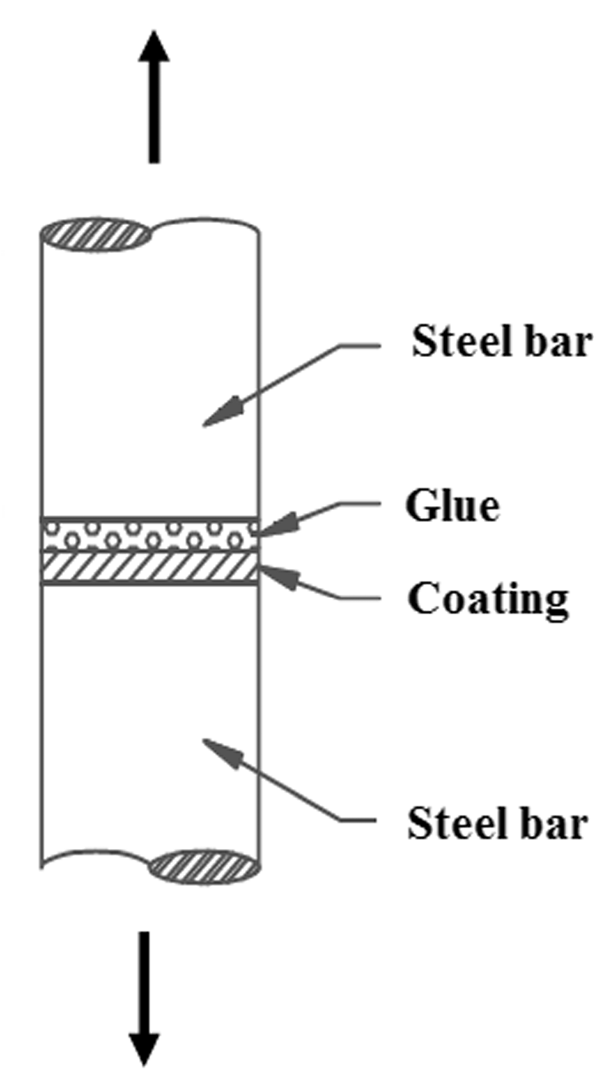
2. Materials and Methods
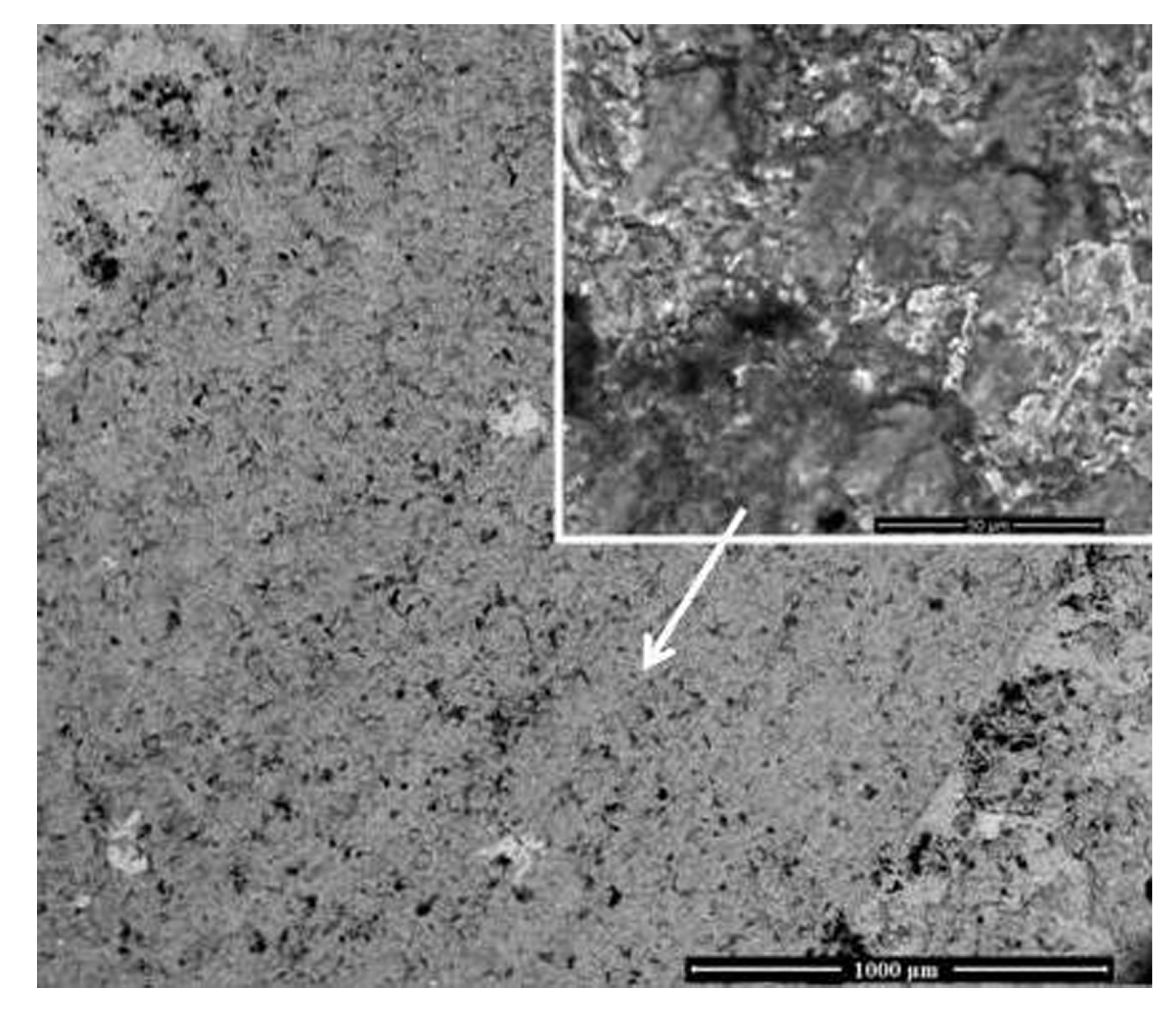
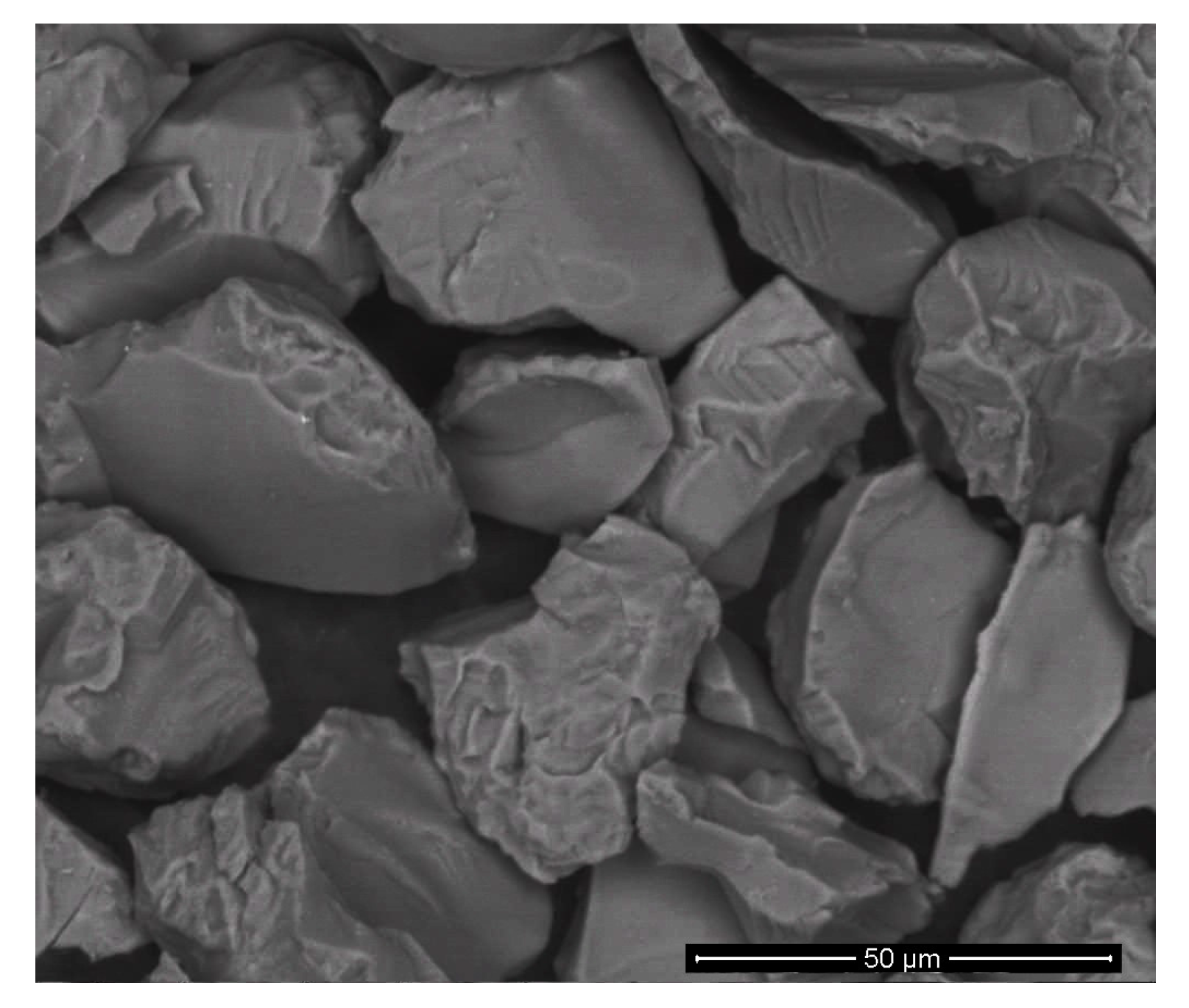
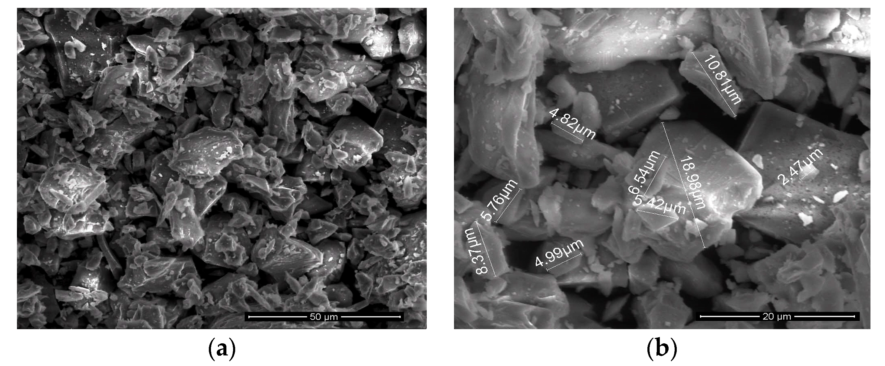
Zircon sand (naturally available) powder has been used as a starting material for the preparation of the coatings. Corrosion-resistant steel plates (Fe-0.12C-0.90Mn-0.025P-0.01S-16Cr-0.20Cu, all in wt %,) were employed as substrates. Steel substrates were sandblasted by alumina grits prior to spraying [21,22,23,24]. The grit blasted samples were cleaned in an ultrasonic bath and coatings were deposited immediately after cleaning. In this study, a multi-chamber, vertically mounted, gas-dynamic accelerator (MCDS) [21,22,23,24] was employed to deposit the coatings on corrosion-resistant steel substrates. The coatings were deposited with a frequency of 16 Hz. The zircon sand was sprayed according to the spray parameters given in Table 1.
The microstructure and elemental composition of the specimens were studied by a scanning electron microscope (Quanta 200 3D, SEM, FEI Company, Eindhoven, The Netherlands) and an optical inverted microscope (Olympus GX51, Olympus Corporation, Tokyo, Japan). Porosity was determined with the metallographic method [22,23,24,29,30,31]. X-ray analysis was done using a diffractometer Rigaku Ultima IV (Rigaku Corporation, Tokyo, Japan). Crystalline phases were identified by the ICDD PDF-2 (2008) powder diffraction database [22,23,24]. Micro-hardness was determined by an automatic micro-hardness tester DM-8B (Affri, Induno Olona, Italy) with a test load of 200 g. Fracture toughness of the coatings was determined by the indentation method at a 300 g load. The fracture toughness (Kc) was evaluated using a well-established formulation by Evans and Wilshaw [32]. The tribological evaluation of the coated substrates under dry conditions was performed using a ball on a disc tribometer CSM Instrument according to ASTM wear testing standard G-99 (Table 1) [33]. All tests were performed at 25 °C with a relative humidity of approximately 50%. During testing the friction coefficient was recorded as a function of the sliding distance. A quantitative estimate of the wear resistance of specimens and the counterbody was made using the wear factor W; a method for calculating the wear factor is presented in Reference [34]. The wear factor is expressed as Equation (1):
W = V / ( P l )
where W is the wear rate, mm3·(m∙N)−1; V is the volume of the removed material, mm3; P is the load, N; and l is the friction path, m.
The total wear volume was calculated by measuring the track cross-sectional area with a stylus profilometer (Taylor-Hobson) at ten different locations along the wear track. Specimen volume losses (mm3) during wear were calculated by Equation (2):
V sample = S l
where S is the area of the section of a wear groove, mm2.
The appearance of wear spots on the balls was examined using an Olympus GX 51 inverted optical microscope. The volume of the material removed from the ball was determined by Equation (3):
V = π h 2 ( r ( 1 / 3 ) h )
where h = r ( r 2 [ d / 2 ] 2 ) 1 / 2 ; d is the diameter of the wear spot, mm; r is the radius of the ball, mm; and h is the height of the segment, mm.
The erosion behavior of coated samples was evaluated by an air jet erosion tester TR-471-400 (DUCOM Instruments, Bangalore, India). Erosion testing was carried out as per ASTM G76 standard at room temperature [35]. Impact velocity was measured using the double disc rotating method [36]. The erosion testing parameters are given in Table 2. Alumina particles of 50 µm size were used as an erodent (Figure 1).
Before erosion testing, the sample was weighed using an electronic balance with least count of 0.01 mg. The samples were subjected to erosion testing of 1 h. After that, the sample was weighed to determine the weight loss. Erosion value was calculated with the volume loss ratio and speed of supply abrasive particles using Equation (4):
( m 0 m 1 ) / ρ / S
where m 0 is the mass of the sample before the test; m 1 is the mass of the sample after the test; ρ is the density of the sample (coating); and S is the velocity of the abrasive particles. The steady state eroded surface was examined using a Digital Video Microscope HIROX KH-7700 3D (Hirox-USA Inc., Hackensack, NJ, USA).
Adhesion tests were carried out following the ASTM C633 standard [37] using an Instron 5882 testing machine (Instron Corporation, Norwood, MA, USA). The experimental setup consisted of identical cylindrical rods (measuring 25.4 mm in diameter and 50 mm in height) screwed into a tensile machine on one of their tips where on another tip the thermal spray samples were glued, as seen in Figure 2. Adhesive glue with a tensile fracture strength of over 70 MPa was used.

3. Results

The particulars of the zircon powder are listed in Table 3. SEM micrographs of the feedstock powder are shown in Figure 3.
Zircon powder consists of irregularly shaped particles with sharp facets. The powder consisted of crushed particles with the main fraction being 2.56–46.48 μm (Table 3).
Table 3 gives the average chemical composition of the particles expressed as weight percentages of the constituents. Figure 4 shows the results of the X-ray diffraction (XRD) of the zircon sands and coatings. The XRD (Figure 4a) and EDX analyses determined that the major component of the sand was ZrSiO4 (Table 3).
Figure 5 presents the SEM micrographs (back-scattered electron mode) of the polished cross-sections of the zircon-based coatings (210–250 μm thick). No vertical cracks were observed in the coating. As shown in Figure 5, the sample had a wavy and stratified structure with piled-up flattened particles. In the structure of the coating, the lamellar structure was poorly visible, and the boundaries of the lamellas were diffuse.
The interface between the coating and the substrate had no visible macro defects. The metallographic porosity of the coatings was very low (Table 3).
Figure 4b shows the XRD patterns for the zircon based coatings that were deposited by the MCDS. Zircon (ZrSiO4) was the major identified phase in the powder (Figure 4a). As shown in Figure 4b, the coatings underwent a phase transformation during spraying. In the XRD pattern (Figure 4b) of the surface coating peaks corresponding to monoclinic ZrO2, cubic ZrO2 and SiO2 phases were observed after deposition. A high temperature modification (cubic) was found as a consequence of the faster heat transfer to the layer and, consequently, a faster local cooling rate. The low temperature monoclinic phase was detected as a result of the lower local cooling rate in larger regions of splats, which was supported by the results obtained in [1,19].
The microhardness of the zircon based coatings was 526 ± 65 HV0.2 (Table 3). The difference in the microhardness values of the coatings was related to the phase composition and the size of the prints at a load of 200 g.
The results of fracture toughness are shown in Figure 6. The crack pattern was identified as crack type I, where dominant cracks occurred parallel to the substrate and emanated from one or two corners of the horizontal diagonal of impression [38].
The tribological properties of the zircon based coating are shown in Table 3. The coatings show the low specific wear rate, 11.75 × 10⁻⁵ mm3·(m∙N)−1. During testing, the contact surfaces of the samples and counterbodies were studied. The wear track of the sample observed by SEM is shown in Figure 7. The wear track of the sample (Figure 7) shows the presence of wear scars along the sliding direction typical for a wear surface and the presence of ploughing grooves and delamination at certain regions similar to that reported in References [39,40,41,42]. The process of coating wear was accompanied by cracking of the coating. Solid phase grains delaminated from the wear surface, which led to the appearance of an abrasive medium in the contact zone (Figure 7) [42]. The delamination cracks did not lead to significant delamination of the zircon-based ceramic coatings. According to Archard’s wear equation [43,44], the wear volume is proportional to the normal load and sliding distance and inversely proportional to the hardness under investigation. The lower the hardness, the larger the wear volume, or the wider and deeper the wear track. The hardness of the zircon based coating was higher than that of the substrate (Table 3); the friction coefficient of the zircon based coating (0.41) was smaller than that of the substrate (0.69); and the wear track of the treated sample was narrower than that of the substrate under the same conditions. All these indicated that the zircon based coating had effectively improved the wear resistance of steel.
The results of the erosion resistance of the coatings are shown in Table 3. Samples were eroded with angles 30°, 60° and 90°. It was established that increasing the impact angle raised the erosive rate of the zircon-based ceramics coatings (Table 3). Erosion areas formed as elliptical shapes for 30° and 60° (Figure 8a), and as round shapes for 90° (Figure 8b). The elliptical shape was formed due to a higher flow divergence of the abrasive particles where the corners of hitting were 30° and 60° [45]. It is known that the removal of material from the surface occurs due to plastic deformation for small angles (less than 30°), and due to the formation of microdefects and subsequent ductile fractures for bigger angles (90°) [46].
The adhesion strength of the coating was given if the failure occurred at the coat-substrate interface. The cohesive strength of the coating was given if the rupture was completely within the coating [47,48]. The results obtained from the tensile testing are presented in Table 3 and Figure 9. The tensile bonding strength of zircon-based ceramic coatings on steel substrates ranged from 13.0 to 13.5 MPa. Zircon-based ceramic coatings did not peeled off due to internal fracture at a load of about 13 MPa, which implied that in this case, the adhesion strength of the coating exceeded the cohesive strength of the coating and adhesive strength of the adhesive. Coating destruction was cohesive in the inter- and intra-lamellar structure of coating.

4. Conclusions

It was experimentally demonstrated that the zircon-based ceramic coatings could be manufactured on corrosion resistant steel without a sublayer by a new multi-chamber gas-dynamic accelerator. The main results can be summarized as follows:
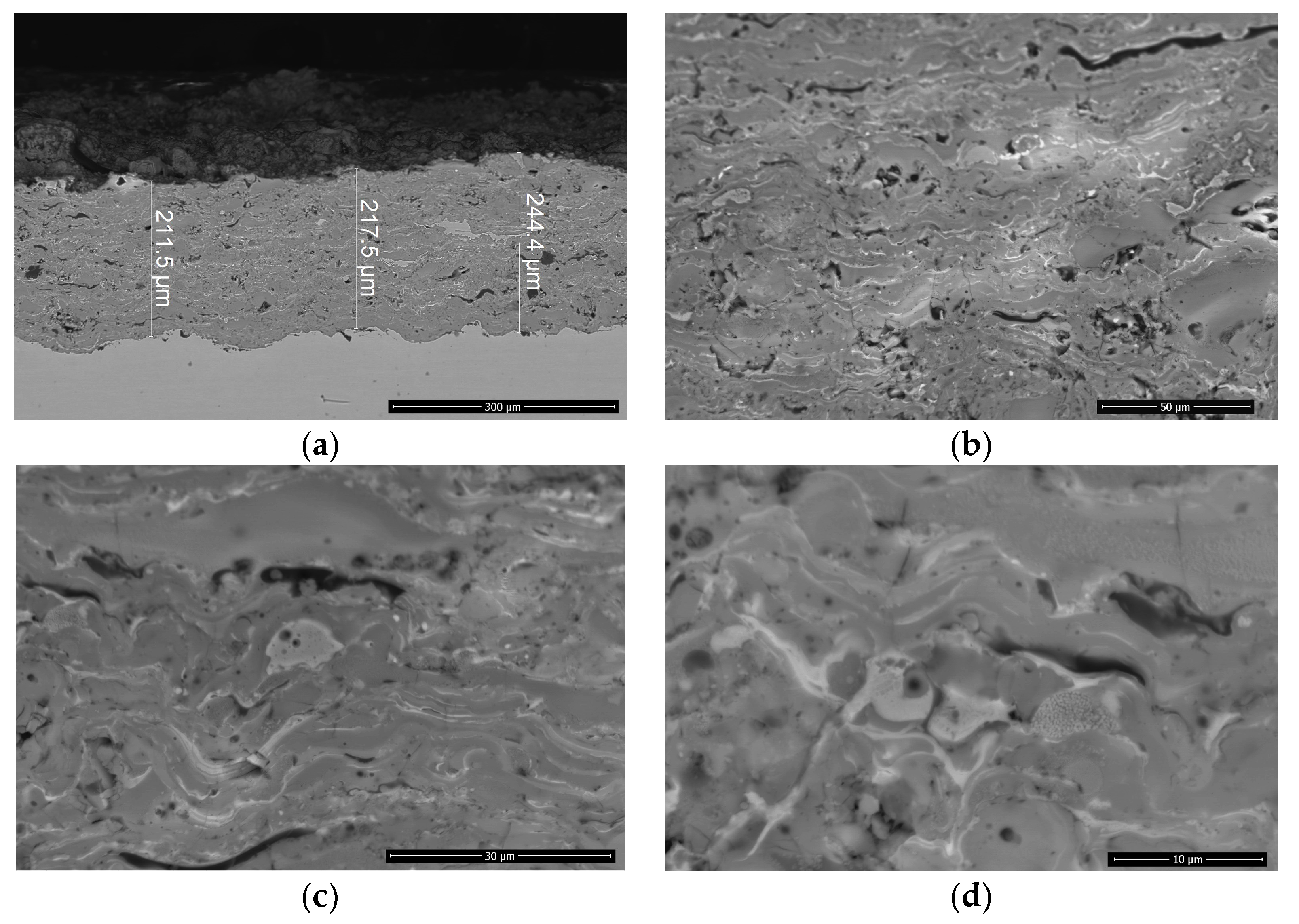
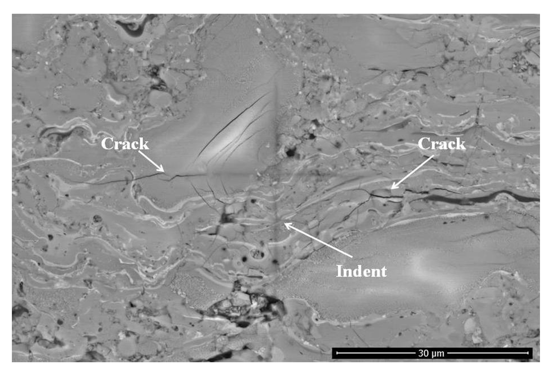
  • The zircon-based ceramic coatings were characterized by low porosity (0.1%), a relatively high hardness of 526 ± 65 HV0.2 and fracture toughness of 2.5 ± 0.6 МPа∙m1/2;
  • The coatings showed a low specific wear rate, 11.75 × 10⁻⁵ mm3·(m∙N)−1;
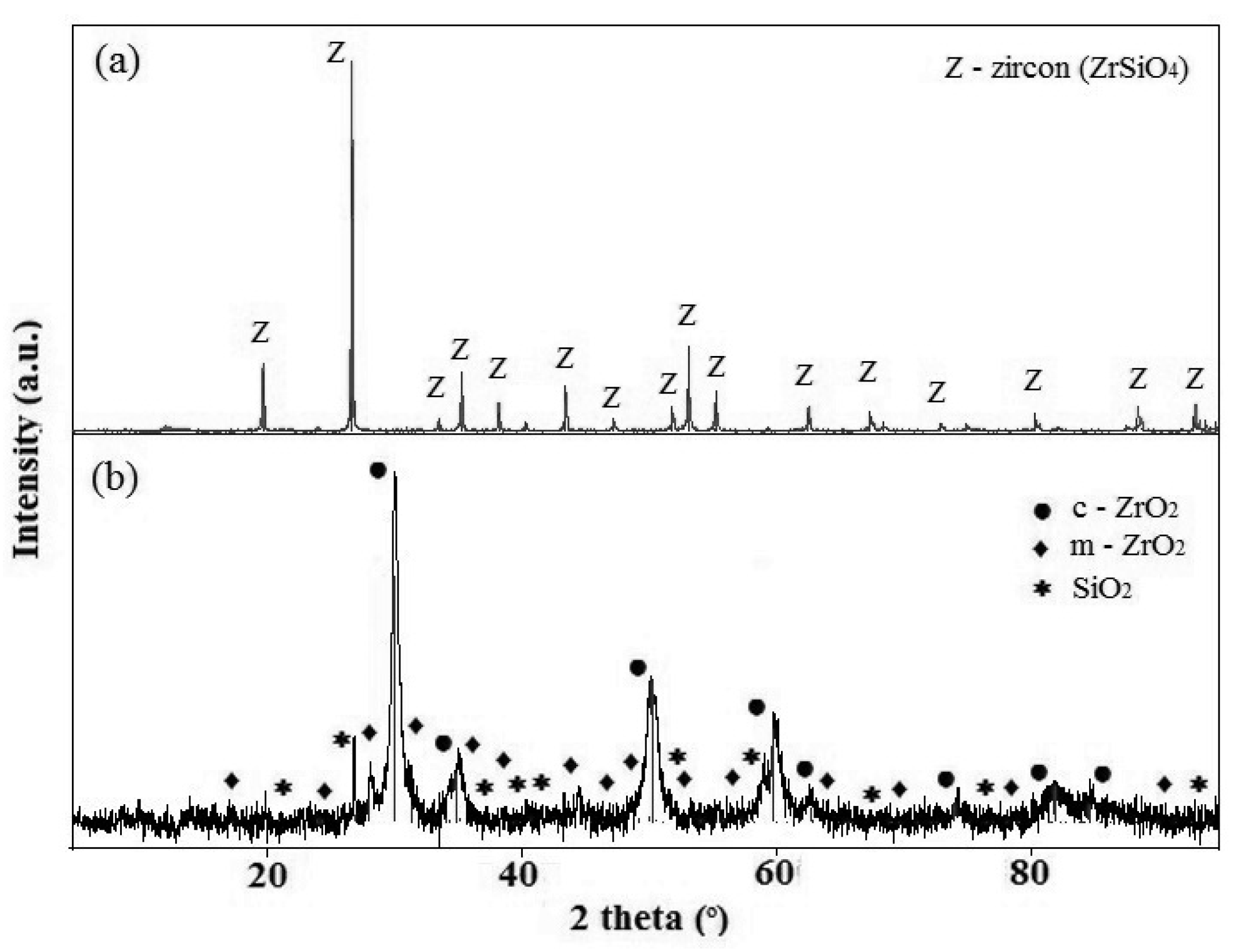
  • The XRD results revealed that the coating consisted of the monoclinic and cubic ZrO2 phases, and SiO2 phase;
  • The coating layer showed a low average erosion rate;
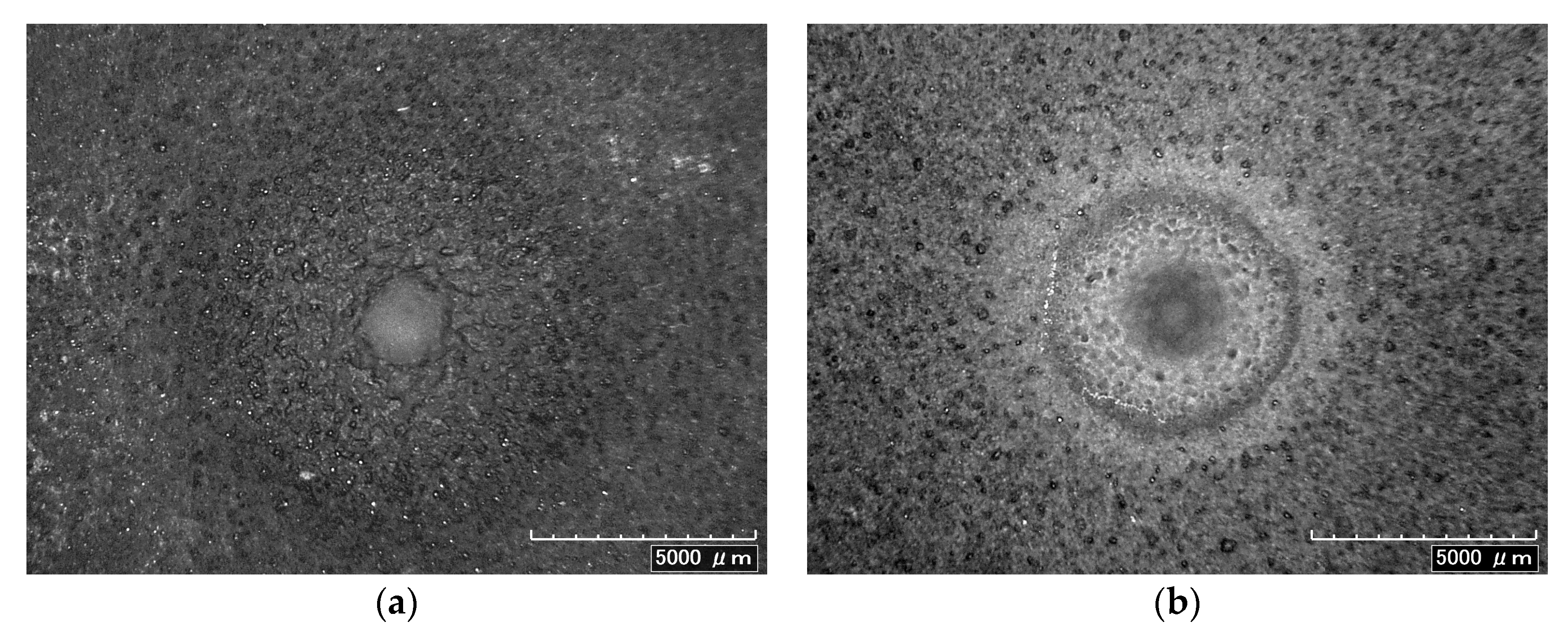
  • The cohesion strength between the zircon-based ceramic coating and substrate was evaluated as 13.0 ± 0.5 MPa.
The results of this work open up new prospects for the further elaboration of novel, facile and economical technology to make the zircon-based ceramic coatings for practical applications. Zircon is widely used in the industrial field as a refractory material because of its excellent mechanical and chemical properties at high temperature. Zircon (ZrSiO4) is a promising candidate as an environmental barrier coating material because of its excellent tolerance against thermal shock and corrosion. Furthermore, zircon-based ceramic coatings have a wide range of application as protective coatings of steel-molding tools. Zircon-based ceramic coatings can be deposited as functional coatings that are used as protection for the surfaces of molds and cores. Zircon coatings are corrosion-proof, heat- and radiation resistant, and can also be used as thermoregulating coatings to maintain the thermal behavior of space vehicles, nuclear power plants, electrostatic safety systems, etc.

Acknowledgments

The study was financial supported by the Russian Science Foundation under grant No. 15-19-00189. All studies were carried out on the equipment of the Joint Research Center «Technology and Materials» of Belgorod State National Research University.

Author Contributions

Marina Kovaleva, Yuri Tyurin and Oleg Kolisnichenko conceived and designed the experiments; Marina Kovaleva, Yuri Tyurin and Oleg Kolisnichenko performed the experiments; Marina Kovaleva and Mayya Prozorova analyzed the data; Maria Arseenko, Maxim Yapryntsev, Vseslav Novikov, Olga Vagina, Viacheslav Sirota contributed reagents/materials/analysis tools; and Kovaleva Marina wrote the paper.

Conflicts of Interest

The authors declare no conflict of interest.

References

  1. Chráska, P.; Neufuss, K.; Herman, H. Plasma spraying of zircon. J. Therm. Spray Technol. 1997, 6, 445–448. [Google Scholar] [CrossRef]
  2. Rendtorff, N.M.; Grasso, S.; Hu, C.; Suarez, G.; Aglietti, E.F.; Sakka, Y. Dense zircon (ZrSiO4) ceramics by high energy ball milling and spark plasma sintering. Ceram. Int. 2012, 38, 1793–1799. [Google Scholar] [CrossRef]
  3. Suárez, G.; Acevedo, S.; Rendtorff, N.M.; Garrido, L.B.; Aglietti, E.F. Colloidal processing, sintering and mechanical properties of zircon (ZrSiO4). Ceram. Int. 2015, 41, 1015–1021. [Google Scholar] [CrossRef]
  4. Rendtorff, N.M.; Garrido, L.B.; Aglietti, E.F. Mechanical and fracture properties of zircon-mullite composites obtained by direct sintering. Ceram. Int. 2009, 35, 2907–2913. [Google Scholar] [CrossRef]
  5. Rudajevova, A. Thermal properties of plasma-sprayed ZrSiO4 material. Ceram. Int. 1994, 64, 47–51. [Google Scholar] [CrossRef]
  6. Ramaswamy, P.; Seetharamu, S.; Varma, K.B.R.; Rao, K.J. Thermal barrier coating application of zircon sand. J. Therm. Spray Technol. 1999, 8, 447–453. [Google Scholar] [CrossRef]
  7. Subbarao, E.C. Zirconia—An overview. In Science and Technology of Zirconia; Advances in Ceramics; Heuer, A.H., Hobbs, L.W., Eds.; American Ceramic Society: Westerville, OH, USA, 1981; Volume 3, pp. 1–24. [Google Scholar]
  8. Vincenzini, P. Zirconia thermal barrier coatings for engine applications. Ind. Ceram. 1990, 10, 113–126. [Google Scholar]
  9. Suzuki, M.; Inoue, S.S.; Ueno, K. Effect of heat treatment on plasma-sprayed zircon (ZrSiO∙ZrSiO4). Mater. Manuf. Process. 1998, 13, 575–580. [Google Scholar] [CrossRef]
  10. Sun, C.; Li, H.-J.; Fu, Q.-G.; Li, H.-L.; Wang, Y.-J.; Wu, H. ZrSiO4 oxidation protective coating for SiC-coated carbon/carbon composites prepared by supersonic plasma spraying. J. Therm. Spray Technol. 2013, 22, 525–530. [Google Scholar] [CrossRef]
  11. Suzuki, M.; Sodeoka, S.; Inoue, T. Zircon-based ceramics composite coating for environmental barrier coating. J. Therm. Spray Technol. 2008, 17, 404–409. [Google Scholar] [CrossRef]
  12. Okubo, T.; Yonemochi, O.; Maeda, M.; Nakamura, K. Reports of the Government Industrial Research Institute; Government Industrial Research Institute: Nagoya, Japan, 1967; Volume 16.
  13. Krauth, A.; Meyer, H. Modifications produced by chilling and their crystal growth in the system containing zirconium dioxide. Ber. Deut. Keram. Ges. 1965, 42, 61–72. (In German) [Google Scholar]
  14. McPherson, R. The Relationship between the mechanism of formation, microstructure and properties of plasma-sprayed coatings. Thin Solid Films 1981, 83, 297–310. [Google Scholar] [CrossRef]
  15. Evans, A.M.; Williamson, J.P.H. Composition and microstructure of dissociated zircon produced in a plasma furnace. J. Mater. Sci. 1977, 12, 779–790. [Google Scholar] [CrossRef]
  16. Raus, P.; Chriska, P. Transmission electron microscope study of a plasma-sprayed zircon coating. Ceram. Silik. 1989, 33, 325–332. (In Czech) [Google Scholar]
  17. Chniska, P.; Dubsky, J.; Kolman, B.; Ilavsky, J.; Forman, J. Study of phase changes in plasma sprayed deposits. J. Therm. Spray Tech. 1992, 1, 301–306. [Google Scholar] [CrossRef]
  18. Schelz, S.; Enguehard, F.; Caron, N.; Plessis, D.; Minot, B.; Guillet, F.; Longuet, J.-L.; Teneze, N.; Bruneton, E. Recombination of silica and zirconia into zircon by means of laser treatment of plasma-sprayed coatings. J. Mater. Sci. 2008, 43, 1948–1957. [Google Scholar] [CrossRef]
  19. Ault, N.N. Characteristics of refractory oxide coatings produced by flame-spraying. J. Eur. Ceram. Soc. 1957, 40, 69–74. [Google Scholar] [CrossRef]
  20. Li, Y.; Khor, K.A. Microstructure and composition analysis in plasma sprayed coatings of Al2O3/ZrSiO4 mixtures. Surf. Coat. Technol. 2002, 150, 125–132. [Google Scholar] [CrossRef]
  21. Vasilik, N.; Tyurin, Y.; Kolisnichenko, O. Method for Gas-Dynamic Detonating Speedup of Powders and Device for Its Implementation. RU Patent 2506341, 11 July 2012. [Google Scholar]
  22. Kovaleva, M.; Tyurin, Y.; Kolisnichenko, O.; Prozorova, M.; Arseenko, M. Properties of detonation nanostructured titanium-based coatings. J. Therm. Spray Tech. 2013, 22, 518–524. [Google Scholar] [CrossRef]
  23. Kovaleva, M.; Tyurin, Y.; Vasilik, N.; Kolisnichenko, O.; Prozorova, M.; Arseenko, M.; Danshina, E. Deposition and characterization of Al2O3 coatings by multi-chamber gas-dynamic accelerator. Surf. Coat. Technol. 2013, 232, 719–725. [Google Scholar] [CrossRef]
  24. Kovaleva, M.; Tyurin, Y.; Vasilik, N.; Kolisnichenko, O.; Prozorova, M.; Arseenko, M.; Yapryntsev, M.; Sirota, V.; Pavlenko, I. Effect of processing parameters on the microstructure and properties of WC-10Co-4Cr coatings formed by a new multi-chamber gas-dynamic accelerator. Ceram. Int. 2015, 41, 15067–15074. [Google Scholar] [CrossRef]
  25. Kovaleva, M.; Tyurin, Y.; Vasilik, N.; Kolisnichenko, O.; Prozorova, M.; Arseenko, M.; Sirota, V.; Pavlenko, I. Effect of heat treatment on the microstructure and microhardness of nanostructural Al2O3 coatings. J. Therm. Spray Technol. 2014, 23, 1199–1209. [Google Scholar] [CrossRef]
  26. Kovaleva, M.; Prozorova, M.; Arseenko, M.; Tyurin, Y.; Kolisnichenko, O.; Vasilik, N.; Sirota, V.; Pavlenko, I. Deposition and characterization of alumina-titania coating by multi-chamber gas-dynamic sprayer. Results Phys. 2015, 5, 1–2. [Google Scholar] [CrossRef]
  27. Prozorova, M.; Kovaleva, M.; Arseenko, M.; Tyurin, Y.; Kolisnichenko, O.; Vasilik, N.; Sirota, V.; Yapryntsev, M.; Pavlenko, I.; Mamunin, K. Microstructure and mechanical properties of alumina powder coatings by a new multi-chamber detonation sprayer. Surf. Rev. Lett. 2016, 23, 1550088. [Google Scholar] [CrossRef]
  28. Kovaleva, M.G.; Prozorova, M.S.; Arseenko, M.Y.; Yapryntsev, M.N.; Vagina, O.N. Properties and peculiarities of ceramic coatings on the Al2O3 and ZrSiO4 basis formed by a new multi-chamber gas-dynamic accelerator. IJAC 2016, 12, 593–601. [Google Scholar]
  29. Sridhar, G.; Ghosh, S.; Chowdhury, N.G. Materials Characterization Techniques: Principles and Applications; National Metallurgical Laboratory (Council of Scientific & Industrial Research): Jamshedpur, India, 1999; pp. 163–176. [Google Scholar]
  30. ASTM-E-3-86 Standard Methods of Preparing Metallographic Specimens; American Society for Metals: Geauga, OH, USA, 1986; Volume 03.01, p. 12.
  31. Moskal, G.J. The porosity assessment of thermal barrier coatings obtained by APS method. J. Achiev. Mater. Manuf. Eng. 2007, 20, 483–486. [Google Scholar]
  32. Evans, A.G.; Wilshaw, T.R. Quasi-static solid particle damage in brittle solids—I. Observations analysis and implications. Acta Metall. 1976, 24, 939–956. [Google Scholar] [CrossRef]
  33. ASTM-G-99-05 Standard Test Method for Wear Testing with a Pin-on-Disk Apparatus; ASTM: West Conshohocken, PA, USA, 2010; Volume 03.02, p. 6.
  34. Vershinin, D.S.; Smolyakova, M.Y.; Manokhin, S.S.; Druchinina, O.A.; Akhmadeev, Y.K. Study of tribological properties of VT16 nitrated titanium alloy with use automated friction machine. Zavod. Labor. Diagn. Mater. 2010, 76, 45–49. [Google Scholar]
  35. ASTM G76-13 Standard Test Method for Conducting Erosion Tests by Solid Particle Impingement Using Gas Jets; ASTM: West Conshohocken, PA, USA, 2013; Volume 03.02, p. 12.
  36. Ruff, A.W.; Ives, L.K. Measurement of solid particle velocity in erosive wear. Wear 1975, 35, 195–199. [Google Scholar] [CrossRef]
  37. ASTM C 633-79 Standard Test Method for Adhesion or Cohesion Strength of Thermal Spray Coatings; ASTM: West Conshohocken, PA, USA, 1985; Volume 15.02, pp. 340–346.
  38. Li, Y.; Khor, K.A. Plasma spray processing of alumina + zircon mixtures. Process. Fabr. Adv. Mater. VIII. 2001, 469–476. [Google Scholar] [CrossRef]
  39. Attar, H.; Ehtemam-Haghighi, S.; Kent, D.; Okulov, I.V.; Wendrock, H.; Bӧnisch, M.; Volegov, A.S.; Calin, M.; Eckert, J.; Dargusch, M.S. Nanoindentation and wear properties of Ti and Ti-TiB composite materials produced by selective laser melting. Mater. Sci. Eng. A 2017, 688, 20–26. [Google Scholar] [CrossRef]
  40. Prashanth, K.; Scudino, S.; Chaubey, A.; Löber, L.; Wang, P.; Attar, H.; Attar, H.; Schimansky, F.P.; Pyczak, F.; Eckert, J. Processing of Al-12Si-TNM composites by selective laser melting and evaluation of compressive and wear properties. J. Mater. Res. 2016, 31, 55–65. [Google Scholar] [CrossRef]
  41. Attar, H.; Prashanth, K.G.; Chaubey, A.K.; Calin, M.; Zhang, L.C.; Scudino, S.; Eckert, J. Comparison of wear properties of commercially pure titanium prepared by selective laser melting and casting processes. Mat. Lett. 2015, 142, 38–41. [Google Scholar] [CrossRef]
  42. Ehtemam-Haghighi, S.; Prashanth, K.G.; Attar, H.; Chaubey, A.K.; Cao, G.H.; Zhang, L.C. Evaluation of mechanical and wear properties of TixNb7Fe alloys designed for biomedical applications. Mater. Des. 2016, 111, 592–599. [Google Scholar] [CrossRef]
  43. Wang, Q.; Zhang, P.-Z.; Wei, D.-B.; Chen, X.-H.; Wang, R.-N.; Wang, H.-Y.; Feng, K.-T. Microstructure and sliding wear behavior of pure titanium surface modified by double-glow plasma surface alloying with Nb. Mater. Des. 2013, 52, 265–273. [Google Scholar] [CrossRef]
  44. Archard, J.F. Contact and rubbing of flat surface. J. Appl. Phys. 1953, 24, 981–988. [Google Scholar] [CrossRef]
  45. Praveen, A.S. Erosion wear behavior of plasma sprayer NiCrSiB/Al2O3. Int. J. Refract. Metals Hard Mat. 2015, 52, 209–218. [Google Scholar] [CrossRef]
  46. Zhang, Y.; Cheng, Y.B.; Lathabai, S. Erosion of alumina ceramics by air and water-suspended garnet particles. Wear 2000, 240, 40–51. [Google Scholar] [CrossRef]
  47. Pawlowski, L. The Science and Engineering of Thermal Spray Coating, 2nd ed.; John Wiley & Sons: New York, NY, USA, 2008. [Google Scholar]
  48. Hjorhhede, A.; Nylund, A. Adhesion testing of thermally sprayed and laser deposited coatings. Surf. Coat. Technol. 2004, 28, 208–218. [Google Scholar] [CrossRef]
Figure 1. SEM micrographs showing the morphology of the blocky alumina erodent particles (back-scattered electron mode).
Coatings 07 00142 g001
Figure 2. Samples assembled for the bond test and applied tensile load.
Coatings 07 00142 g002
Figure 3. SEM micrographs of zircon powder (back-scattered electron mode). (a) ×2000; (b) ×5000.
Coatings 07 00142 g003
Figure 4. XRD patterns of the (a) zircon sands, and (b) the zircon-based ceramics coating.
Coatings 07 00142 g004
Figure 5. SEM micrographs of cross-sections of the zircon-based ceramics coating (back-scattered electron mode). (a) ×500, (b) ×2000, (c) ×5000, and (d) ×10000.
Coatings 07 00142 g005
Figure 6. Microcracking propagation from the Vickers indentation in the zircon-based ceramics coating (SEM, back-scattered electron mode).
Coatings 07 00142 g006
Figure 7. Morphology of the wear track of the zircon-based ceramics coating (SEM, back-scattered electron mode).
Coatings 07 00142 g007
Figure 8. Micrographs of erosion surfaces of the zircon-based ceramics coating after (a) 30° and (b) 90° impingement.
Coatings 07 00142 g008
Figure 9. Macrograph of fractured surface after tensile strength test.
Coatings 07 00142 g009
Table 1. Spraying parameters of zircon coating.
Spray Distance, mmBarrel Length, mmBarrel Diameter, mmPowder Feed Rate, g/hFlow Rate of Fuel Mixture Components, m3/hOxygen/Fuel Ratio
OxygenPropane (100%)Air
5550016550* 3.9/** 3.6* 0.75/** 0.7* 0.1/** 0.115.2
* Cylindrical form combustion chamber; ** Combustion chamber in the form of a disk.
Table 2. Erosion test parameter.
Erodent Velocity, m/sErodent Feed Rate, g/minImpingement Angle, °Nozzle Diameter, mm
602.230, 60 and 901.5
Nozzle to Sample Distance, mmTest Time, minSamples Size, mm3
1060(25 × 20 × 5), (25 × 25 × 5), (25 × 25 × 5)
Table 3. The chemical composition of the powder and coating, as well as the mechanical features of coating.
Chemical Composition and Mechanical FeaturesPowderCoatingSteel
Chemical Composition (wt %)
Zr77.4861.03
Si8.2311.17
O13.7712.75
Fe0.467.40
Al0.070.73
C 6.920.12
Fe base
Mn 0.90
P 0.025
S 0.01
Cr 16.0
Cu 0.20
Particle size Distribution (μm)
d(0.1)2.56
d(0.5)18.29
d(0.9)46.68
Porosity, ± 0.05% 0.10
Microhardness (HV0.2) 526 ± 65187 ± 12
Fracture Toughness, ± 0.6 МPа∙m1/2 2.5
Specific Wear Rate∙(× 10−5) *, ** [mm3·(m∙N)−1] 11.7548.54
Avg. Erosion Rate (10−3) (mm3/g)
Impact Angle30° 2.921.7
60° 3.426.0
90° 8.128.0
Average Adhesion (MPa), Fracture Mechanism 13, Cohesive
* Counterbody (a 6 mm in diameter aluminum oxide ball), 6 N normal load, 0.15 m∙s−1 sliding speed, a total sliding distance of 1200 m; ** Surface roughness (polished surface) Ra = 3.04 ± 0.01 µm.

