Study of Electroless Nickel Coatings on EN-GJS-500-7 Spheroidal Graphite Cast Iron


SIMaP, Université Grenoble Alpes, CNRS, Grenoble-INP, Grenoble 38000, France
*
Author to whom correspondence should be addressed.
Coatings 2018, 8(7), 239; https://doi.org/10.3390/coatings8070239
Submission received: 25 May 2018
/
Revised: 17 June 2018
/
Accepted: 4 July 2018
/
Published: 6 July 2018
Abstract
:EN-GJS-500-7 spheroidal graphite (SG) cast iron was coated with chemical Ni-P. The kinetic study reveals that the limiting step corresponds to a classical surface process, but the morphological study shows, at short times, an imperfect Ni-P coating on the graphite spheroids. The initial Ni-P growth appears to be blocked. This problem has been solved by the application of a cathodic polarization for a few minutes as a pretreatment of the surface. It was observed after this first step that both chemical and electrochemical reduction of nickel cation and hypophosphite on the SG cast iron took place at the same time, leading to the growth of a homogeneous Ni-P scale, in particular on graphite spheroids.
1. Introduction
Spheroidal graphite (SG) cast iron, also called ductile iron or nodular iron, is widely used in the mechanical engineering industry. For parts, such as motors, turbines, compressors, and pipes, they stand out for their mechanical properties. The friction coefficients related to the fluids circulating are low. The self-lubricating nature of the graphite reduces the friction force on the surface [1,2,3], but also explains the good machinability of these materials. The damping and vibration resistance is also an essential property to ensure the accuracy of gear rotations [1]. Finally, SG cast iron exhibits good resistance in oxidizing media. The high silicon content allows the formation of a protective compact and adherent iron silicate scale (Fe2SiO4) [4,5]. However, in aggressive industrial environments, such as halogenated media (F2, Cl2, HBr), the corrosion resistance is not sufficient. The formation of volatile iron halides leads to catastrophic corrosion [6]. A surface protection is, thus, needed, such as phosphorus electroless nickel plating. Nickel is more noble than iron (the standard potential = −0.257 V/SHE > = −0.447 V/SHE) [7], and does not form volatile species with halogens. In addition, plating with high phosphorus content (10–13 wt %) gives an amorphous scale and limits the diffusion of oxidizing species due to the absence of grain boundaries known to act as preferential diffusion paths [8,9,10,11]. It should also be underlined that electroless plating provides an even deposit regardless of the workpiece geometry and is preferred over electroplating. The absence of a current avoids the effects of field, which create extra thicknesses on the edges and a lack of deposit in the holes. However, in the case of an electrochemical process, the driving force can be controlled (via the applied potential) and can improve the quality of deposits as it can be shown during this work, with high-phosphorus electroless nickel plating associated to Ni electroplating being studied.
2. Materials and Methods
2.1. Material
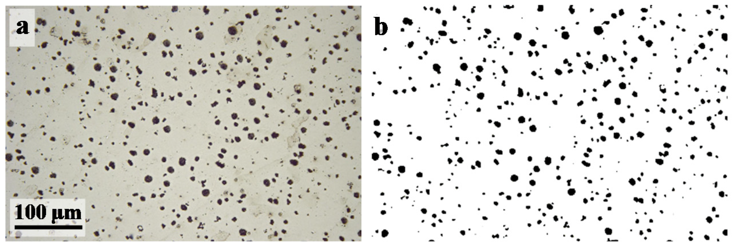
EN-GJS-500-7 cast iron, according to the European standard DIN EN 1563 (Table 1), was supplied by UCB Cast Profil S.A. and has a ferritic-pearlitic matrix. The addition of silicon, which is a graphitizing element, allows the carbon to precipitate in the form of graphite. Magnesium promotes the solidification of graphite in a spheroidal form [12]. A material with a chemically heterogeneous surface is, thus, obtained, as observed in Figure 1a (spheroids appear in black). After image thresholding and particle analysis (Figure 1b), the percentage of graphite area covering the surface was measured (3.3%), as well as the average diameter of the graphite spheres (d = 11 μm), with a standard deviation of σ = 2.8. The distribution of spheroids appears to be homogeneous. The EN-GJS-500-7 cast iron will be named SG cast iron in the rest of this paper.
2.2. Experimental Setup for Electroless Ni-P Coating Deposition
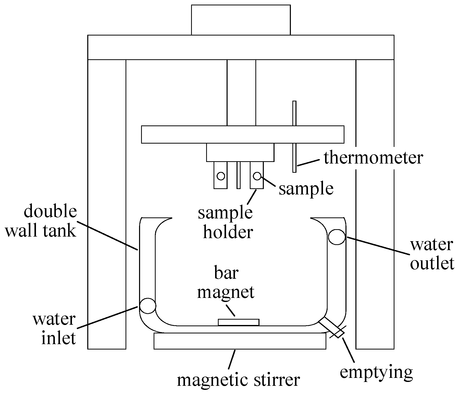
A lab-made glass cell (double walled), developed for electroless Ni-P coating deposition, is presented in Figure 2. The use of glass prevents nickel deposition on the internal walls of the reactor. The double jacket allows the passage of a heat transfer fluid, which ensures the stability of the bath temperature. A Teflon sample holder is resistant to temperature and acids. The nickel plating is performed on circular samples with a diameter of 12 mm and a thickness of 2 mm. Samples were SiC ground up to the grade 1200, then 1 µm diamond paste polished, ultrasonically cleaned in a 50/50 ethanol-acetone mixture, and, finally, rinsed in deionized water before being dried. The deposition is carried out in a commercial bath. Constant magnetic stirring ensures homogeneity. The temperature, fixed at 84 °C, corresponds to the optimum set by the bath supplier to have a high deposition rate without risk of decomposition.
The commercial bath supplied by Coventya, whose exact composition is not given by the supplier, is mainly composed of two elements. A nickel source via nickel sulphate (NiSO4), and a reducing agent, sodium hypophosphite (NaH2PO2), which, by oxidizing, allows the reduction of nickel [13,14]. In addition, it is the source of phosphorus co-deposited to form a NiP alloy. The bath is also composed of nickel complexing agents, which makes it possible to avoid the precipitation of nickel hydroxide (Ni(OH)2) or nickel orthophosphite (NiHPO3) [15]. The complexing agents also play the role of a buffer to maintain the pH. The optimum set by the manufacturer is pH = 5.8 to have a sufficiently fast deposition rate, while having the desired percentage of phosphorus (10–13 wt %). The presence of stabilizers avoids the decomposition of the bath due to the initiation of nickel plating on seeds present in the solution [16,17]. Finally, the surfactants make it possible to lower the surface tension of the substrate and, thus, increase its wettability. They are also used to remove hydrogen bubbles that form on the surface during the nickel reduction reaction [18] and, thus, improve the regularity of the deposit. Deposits lasting from 5 to 172 min at T = 84 °C were made, as well as 60 min deposits for temperatures in the range 75–93 °C.
2.3. Characterisation Techniques
Surface and cross sections of the samples were observed using an optical microscope (OM) (VHX 5000, Keyence, Osaka, Japan) and a SEM equipped with an energy dispersion spectrometer of X-ray (EDX) (EDAX, Mahwah, NJ, USA) to perform elemental analysis. X-ray Diffraction (XRD) was used for phase identification. Voltammetry was used with a classical three electrode electrochemical cell; a nickel foil (area ~ 0.95 cm2) as the counter electrode and a saturated calomel electrode SCE, +0.241 V vs. Standard hydrogen electrode SHE. The applied potential was controlled by a potentiostat Biologic VSP300 (Bio-logic, Seyssinet-Pariset, France). The electrochemical parameters (corrosion current icorr, corrosion potential Ecorr, etc.) were extracted from the classical Tafel plot with the software EC-Lab (Version 10.44).
3. Results and Discussion
3.1. Kinetic Study
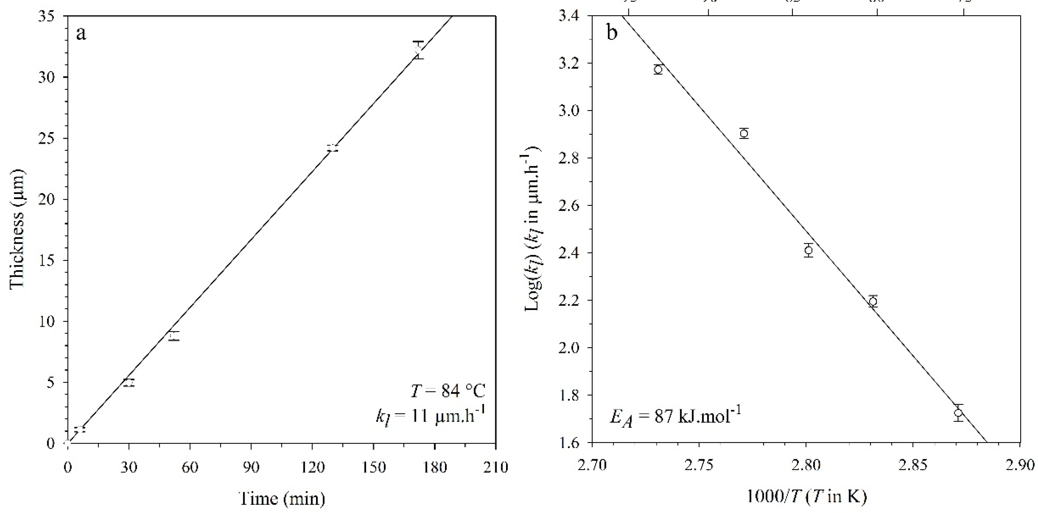
Figure 3a presents the kinetics of the electroless nickel plating measured at T = 84 °C. Thicknesses of the scales have been obtained by optical microscopy observations (cross-sectional views). Two samples have been coated for each experiment and four measurements have been made at different places on each sample. Error bars of Figure 3a,b correspond to the standard deviation calculated from these data. The evolution in Figure 3a appears to be linear in the whole range of time (0 < t < 172 min), with a linear correlation coefficient (LCC) equal to 0.998. The linear kinetic constant, kl, can be extracted as the slope of this evolution and is about 11 µm·h−1. kl was also measured from 75 to 93 °C after one hour. Figure 1b presents the classical Arrhenius plot from which the activation energy, EA, of ~87 kJ·mol−1 (LCC = 0.985) was extracted. This value is consistent with a rate-limiting step of a chemical reaction most probably located at the nickel/electrolyte interface. The chemical deposition of nickel is studied for a long time. In 1947, a first paper proposed by Brenner and Riddel [13] involved an oxidation reaction of hypophosphite:
and two reduction reactions, nickel and hydrogen:
The balance equation of the nickel-plating reaction is:
At that time, the co-deposition of phosphorus to form a NiP alloy is not intended.
More recently, Malecki et al. [19], in 2000, proposed a more detailed mechanism of surface reactions, including adsorbed species:
The model proposes the reduction of nickel cation, Ni2+, but also the reduction of hypophosphite, leading to the co-deposition of Ni and P. The growth of the Ni-P coating is outward and the activation energy measured in the present work suggests that the rate-controlling step could correspond to the charge transfer on nickel (Equation (5)) or a proton (Equation (6)) occurring at the Ni-P surface.
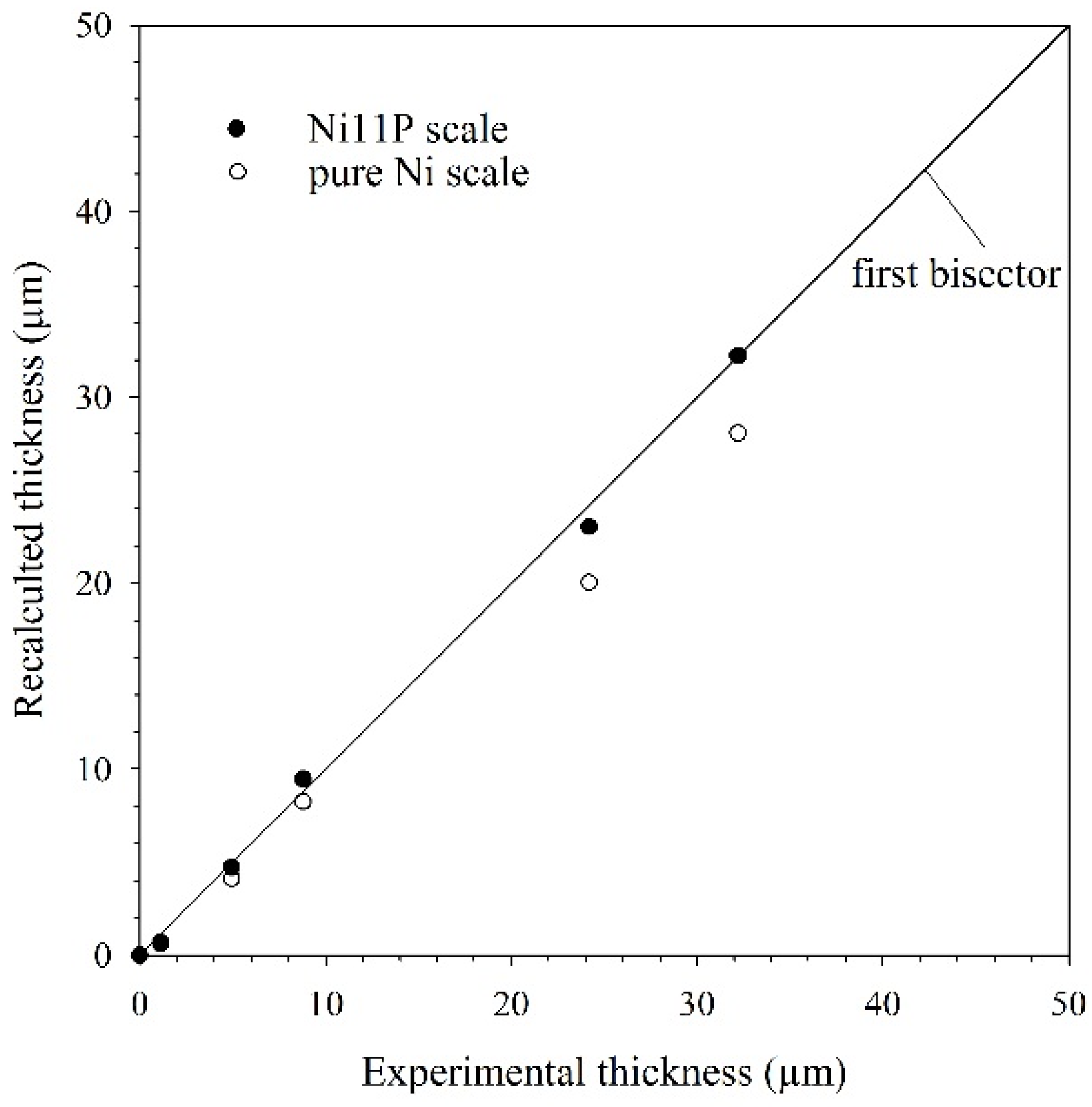
Figure 4 presents recalculated thickness (using mass gain) vs. experimental thickness (observed on cross-sectional views) of scales. The y axis was calculated using two hypotheses. The first one (white points) assumes that scales consist of pure Ni. The second one (black points) assumes that scales contain 11 wt % of P. The calculation has been obtained using a density of Ni11P, ρ = 7.7 g·cm−3 measured from [20]. The good fit between black points and the first bisector suggests that deposits indeed contain P.
3.2. Morphology Study
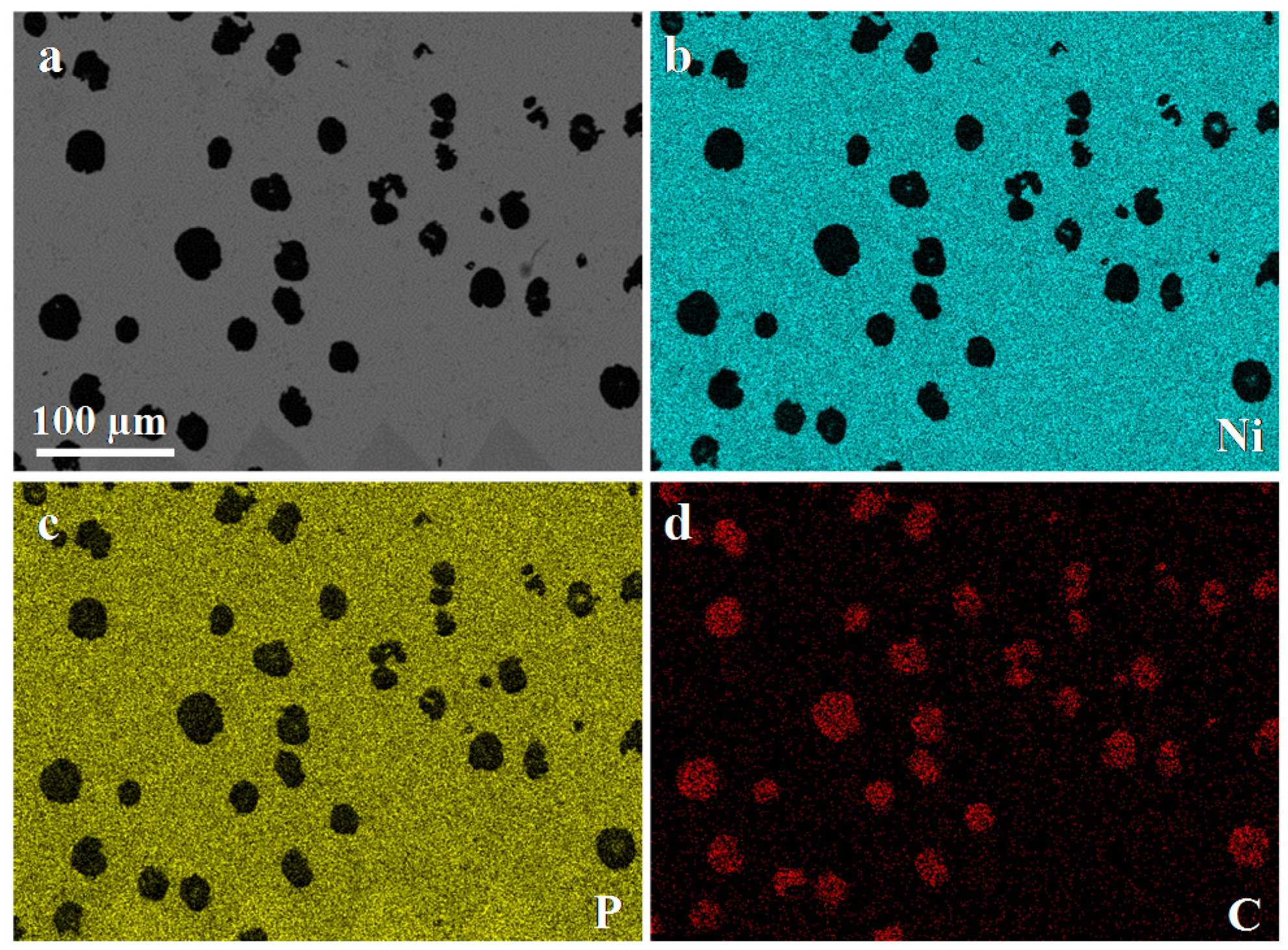
Figure 5 presents a SEM top-view and EDX mappings (Ni, P, and C) of the coating obtained on the SG cast iron after 5 min at T = 84 °C. According to Figure 3a, the Ni-P deposit thickness is around 1 µm. The triangular shapes observed on the bottom of Figure 5a correspond to indents performed to mark the area. Graphite spheroids can be clearly observed (in black) on the SEM top-view. Their presence is confirmed by observing the carbon EDX mapping (Figure 5c). On the other hand, nickel and phosphorus EDX mappings confirm that deposits are made of Ni and P, and these mappings also indicate that neither Ni nor P was deposited on graphite spheroids.
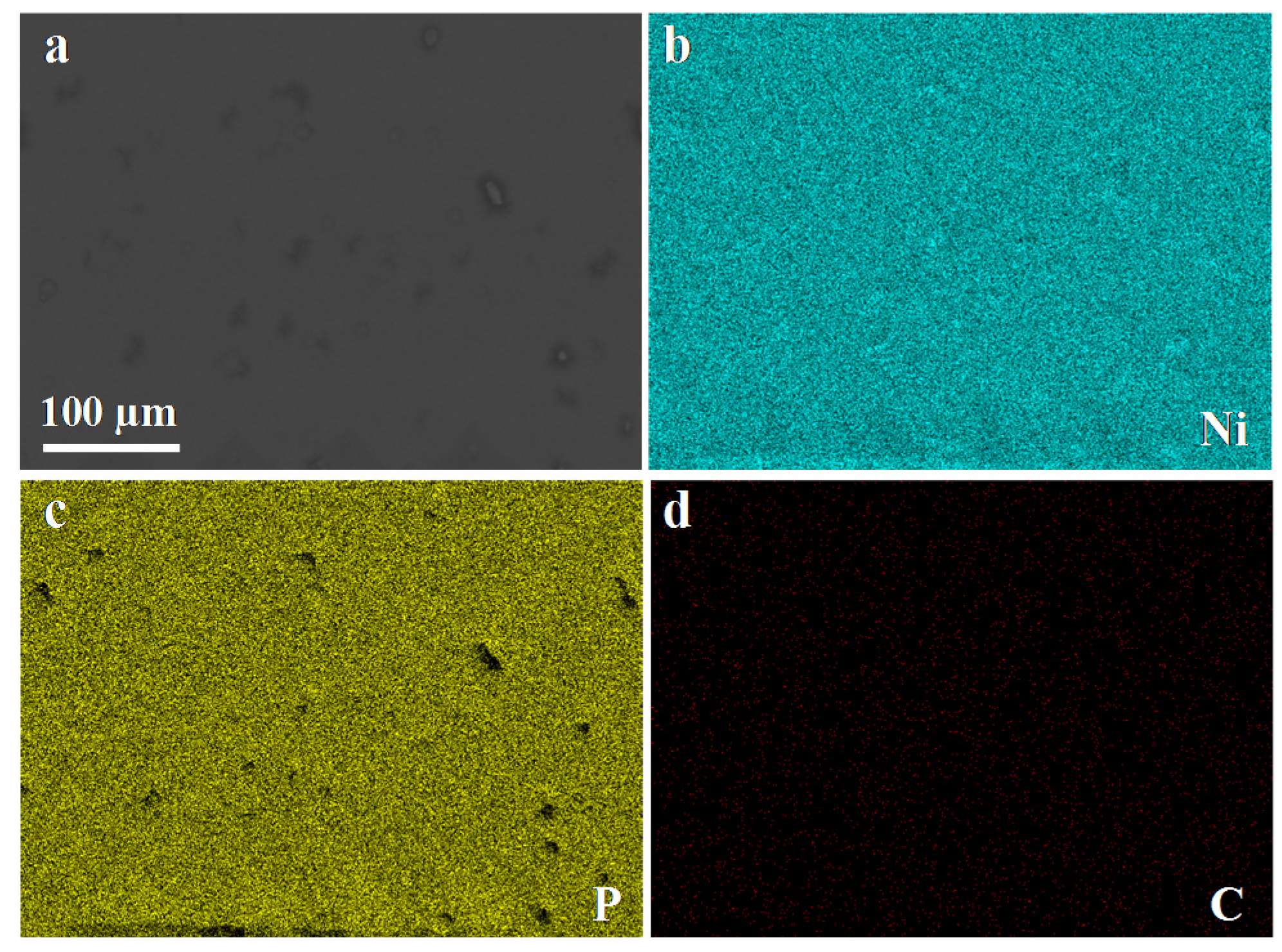
Figure 6 presents the same results at the same temperature, but after 60 min. According to Figure 3a, the Ni-P deposit thickness is now around 10 µm. Contrary to what was observed in Figure 5, the Ni-P appears as a covering coating even if one can observe in Figure 6a–c some shapes that possibly correspond to subjacent graphite spheroids. Nevertheless, the presence of carbon is no longer observed in Figure 6d.
An SEM top-view at higher magnification (Figure 7a) reveals that the Ni-P coating is, in fact, not totally covering. On some places, a charging effect can be observed (SE detector) and the coating seems to have healed by a particular mechanism. The SEM cross-sectional-view (Figure 7b) shows an irregular coating on the SG cast iron matrix, in particular, with the presence of regions of a lesser thickness at the place of a subjacent graphite spheroid. This behavior is problematic, especially regarding the corrosion resistance of the SG cast iron. The electroless nickel plating does not ensure a perfect Ni-P coating and one cannot exclude the presence of porosities above graphite spheroids.
A scenario of Ni-P growth is proposed in three steps (Figure 8). Firstly (t1), the Ni-P coating growth is perpendicular to the SG cast iron surface, but this one is blocked on graphite spheroids. Nevertheless, with time (t2), Ni-P growth continues, including in the direction parallel to the surface. Finally (t3), the Ni-P healing occurs, as it can be observed in Figure 7b. Consequently, one must admit that the initial Ni-P growth is blocked on graphite. The limiting step which is concerned can be:
- The diffusion of Ni2+ in the bath;
- The diffusion of in the bath;
- The adsorption of Ni2+ at the surface of graphite spheroid;
- The adsorption of at the surface of graphite spheroid;
- The charge transfer between and (as presented in Equation (5));
- The electro crystallization (crystal building) of Ni-P; and
- The desorption of at the surface of graphite spheroid.
Steps 1 and 2 must be rejected because of the constant magnetic stirring in the bath. In addition, if step 1 and/or 2 was limiting on graphite, it would also be the case on nickel, which is in contradiction with the previous measurement of the activation energy (see Section 3.1). Step 7 must be also rejected because the graphite is not known to exhibit a high hydrogen over voltage. In these conditions, adsorption of chemical species (3 and 4), charge transfer (5), or electro crystallization of Ni-P (6) can be suspected to be slow on graphite.
This is not a new problem and electroless nickel plating on graphite has been extensively studied. Nevertheless, most of the time, works have investigated coatings on graphite particles of graphite fibers in an alkaline bath [23] or containing specific chemical agents [24]. Chemical activation pretreatment of powder has also proven to be successful in improving the wettability and the activity of graphite [25,26], as well as the electrochemical deposition of Ni on carbon microfiber surfaces using unbuffered NiCl2 [27].
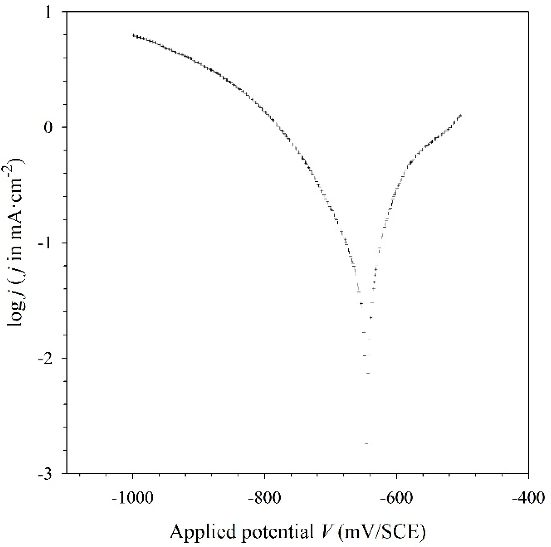
In the present study, an electrochemical polarization was applied at the beginning of a new experiment. It was expected this way to generate a thin covering nickel scale. The originality of this process is to carry out the polarization directly in the commercial chemical nickel bath, and not in a conventional electrolytic nickel bath, such as Watts, Wood, or Strike [28,29]. To determine the optimum potential to apply during this polarization, a voltammogram was primarily recorded at a low temperature (T = 10 °C) to minimize the chemical nickel deposition on the SG cast iron. The results are presented in the form of a Tafel plot in Figure 9. From this plot, the best fit gives a current density, jcorr, of ~19 µA·cm−2 and a potential Ecorr of −645 mV/SCE.
The Ecorr value is in good agreement with the Nernst potentials, E, which can be calculated from Equations (2) and (3), concerning, respectively, the Ni2+ and H+ reduction, and, on the other hand, the oxidation of the SG cast iron according to:
These values are presented in Table 2 using a pH = 5.8 and a concentration of Ni2+ of 10−1 mol·L−1. It should be underlined that the calculation of the Ni Nernst potentials, , provided in the Table 2 is not correct and should consider the Ni activity instead of its concentration, C. However, this activity depends on the exact bath composition which is not known.
In these conditions, it was decided, that to promote the reduction of nickel cations Ni2+ on graphite spheroids, a cathodic potential should be applied, with respect to Ecorr.
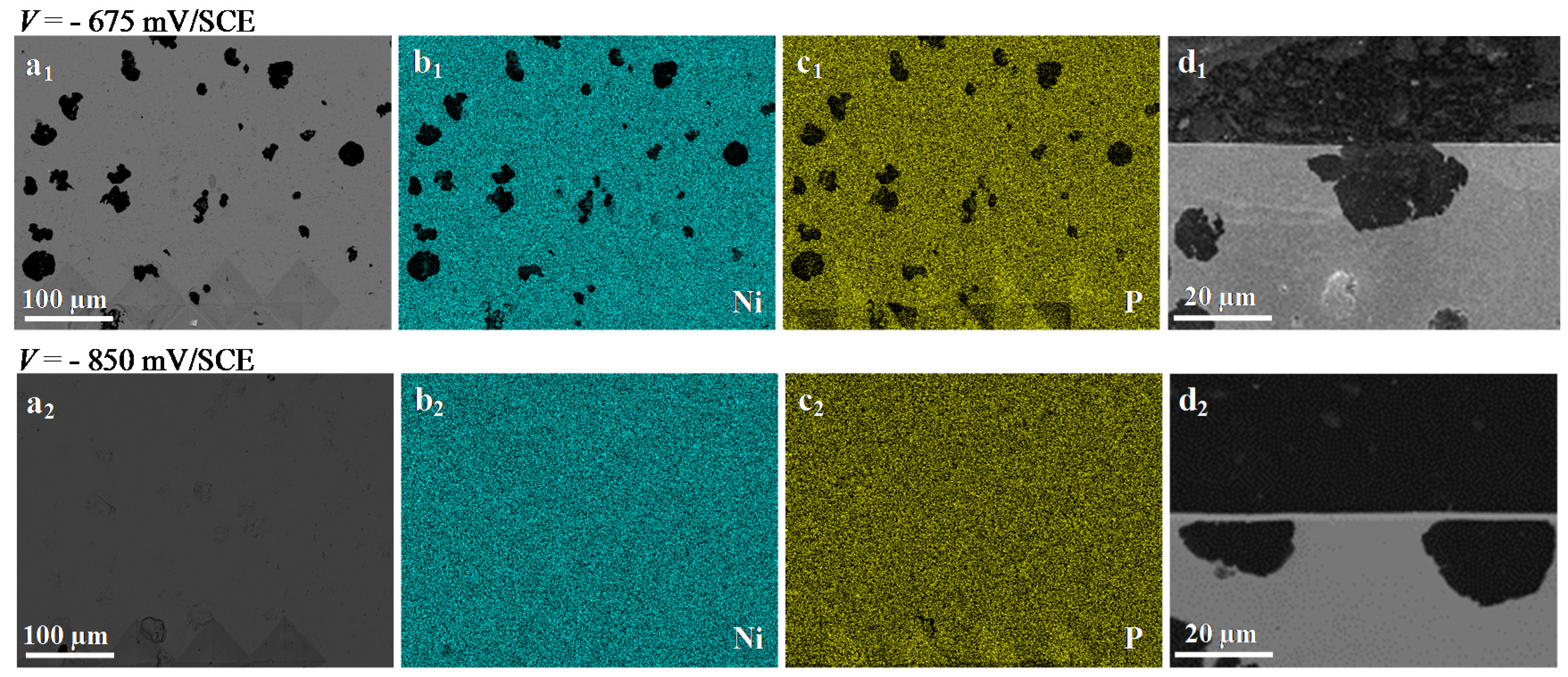
Figure 10 presents a SEM top-view, EDX mappings (Ni and P), and a SEM cross-sectional-view of the coating obtained on the SG cast iron after a 5 min experiment including two steps. Step one corresponds to the polarization of the sample at V = −675 mV/SCE or V = −850 mV/SCE during 3 min. It is assumed during this first step that both the chemical and electrochemical reduction of nickel cation on the SG cast iron will take place at the same time. Step two corresponds to the chemical Ni-P deposit at T = 84 °C during 2 min. At V = −675 mV/SCE, the results are similar to what has been observed without polarization (see previous experiment presented in Figure 5). Graphite spheroids can again be clearly observed on the SEM top-view (in black in Figure 10(a1)). Nickel and phosphorus EDX mappings (Figure 10(b1,c1)) show that neither Ni nor P was deposited on the graphite spheroids and this result was confirmed with the SEM cross-sectional-view (Figure 10(d1)). The polarization appears to be not cathodic enough to ensure the reduction of nickel cations on the substrate. However, at a more cathodic polarization (V = −850 mV/SCE), the Ni-P coating appears to be covering the whole substrate. The SEM cross-sectional-view (Figure 10(d2)) clearly shows a homogeneous Ni-P scale of about 2 µm, in particular on graphite spheroids. This coating, characterized by XRD (result not presented here), confirms that Ni-P is amorphous.
The calculation of the kinetic, with assistance by polarization, gives ~24 μm·h−1. This value is more than twice higher than that calculated in Section 3.1 (~11 μm·h−1). This result shows that both the chemical and electrochemical Ni deposition processes have been probably implied during the experiment.
To approximate the contribution due to the polarization, another experiment was carried out at 10 °C (to block the kinetics of chemical deposition) during 3 min at V = −850 mV/SCE. The current density was equal to 15 mA·cm2. If we consider in the first approach the case of an electro-deposition of pure nickel from Faraday’s law, y, the thickness of the electrodeposited Ni scale can be expressed as:
where j is the current density, MNi is the Ni molar mass, t is the time, n is the number of electrons mole per mole of Ni, F is the Faraday constant, and ρNi is the density of nickel.
The theoretical calculation of y gives 0.92 µm. At the same time, the SEM observation (results not presented here) shows a thin scale of 400 nm in thickness. This implies that the efficiency of the plating is about 40%. This may be explained by the existence of competing reduction reactions, such as that of the hydrogen ion to gaseous hydrogen (which is observed experimentally in the bath) and that of the hypophosphite to phosphorus. Moreover, the electro-deposition is thermally-activated and this experiment, at T = 10 °C, gives a scale thickness that is probably underestimated compared to what could be obtained at T = 84 °C.
It is concluded at this point of the discussion that a short initial polarization of the SG cast iron promotes an amorphous Ni-P covering coating of which a minor part comes from an electro-deposition process. To check if this coating contains P, EDX local analysis at low energy (5 keV) to minimize the electron interaction volume was performed on the cross-sectional view presented in Figure 10(d1). The results give a Ni amount of ~86 wt % and a P amount of ~14 wt %, values which seem reasonable compared to what is expected with classical high phosphorus nickel plating.
However, there remains the question concerning the possible increase of hydrogen incorporation in the deposit during the polarization. This problem, if it does exist, could probably be solved by classical thermal treatments applied to the electroless Ni-P deposits [30]. Further experiments to determine the effect of the polarization on the mechanical properties, as well as the corrosion resistance, of Ni-P deposits presented in this paper are underway.
4. Conclusions
During this study of electroless nickel plating on SG cast iron, it was observed that the Ni2+ reduction is blocked on graphite and leads to a non-covering Ni-P deposit. A pretreatment by the application of a cathodic electrochemical polarization of the substrate in the chemical nickel bath has proven to be successful to promote a thin homogeneous coating, including on the graphite spheroids. It was shown that both the chemical and electrochemical reduction of nickel cations and hypophosphite took place at the same time and gave an amorphous Ni-P deposit. It is expected that this pretreatment could increase the corrosion resistance of SG cast iron, in particular in aggressive environments containing halogen elements, such as fluorine and chlorine.
Author Contributions
Conceptualization, I.F.; G.B. and Y.W.; Methodology, I.F.; G.B. and Y.W.; Investigation, I.F.; G.B. and Y.W.; Writing-Original Draft Preparation, I.F., G.B. and Y.W.; Writing-Review & Editing, I.F.; G.B. and Y.W.; Supervision, Y.W.; Project Administration, Y.W.
Funding
This research received no external funding.
Conflicts of Interest
The authors declare no conflict of interest.
References
- Murray, G. Handbook of Materials Selection for Engineering Applications; CRC Press: Boca Raton, FL, USA, 1997. [Google Scholar]
- Sugishita, J.; Fujiyoshi, S. The effect of cast iron graphite on friction and wear performance III: The lubricating effect of graphite under rolling-sliding contacts. Wear 1982, 77, 181–193. [Google Scholar] [CrossRef]
- Ghasemi, R.; Elmquist, L. Cast iron and the self-lubricating behaviour of graphite under abrasive wear conditions. In Proceedings of the 10th International Symposium on the Science and Processing of Cast Iron, Mar del Plata, Argentina, 13 November 2014. [Google Scholar]
- Gundlach, R.; Doane, D. Heat Treating of High-Alloy Irons; ASM Handbook: Materials Park, OH, USA, 1991; Volume 4, pp. 697–708. [Google Scholar]
- Hashmi, S. Comprehensive Materials Finishing; Elsevier: New York, NY, USA, 2016. [Google Scholar]
- Lai, G.Y. High-Temperature Corrosion and Materials Applications; ASM International: Materials Park, OH, USA, 2007. [Google Scholar]
- Rumble, J. CRC Handbook of Chemistry and Physics, 98th ed.; CRC Press LLC: Boca Raton, FL, USA, 2017. [Google Scholar]
- Ashassi-Sorkhabi, H.; Rafizadeh, S.H. Effect of coating time and heat treatment on structures and corrosion characteristics of electroless Ni–P alloy deposits. Surf. Coat. Technol. 2004, 176, 318–326. [Google Scholar] [CrossRef]
- Balaraju, J.N.; Narayanan, T.S.N.S.; Seshadri, S.K. Evaluation of the corrosion resistance of electroless NiP and NiP composite coatings by electrochemical impedance spectroscopy. J. Solid State Electr. 2001, 5, 334–338. [Google Scholar] [CrossRef] [Green Version]
- Ratzker, M.; Lashmore, D.S.; Pratt, K.W. Electrodeposition and corrosion performance of nickel–phosphorus amorphous alloys. Plat. Surf. Finish. 1986, 73, 74–82. [Google Scholar]
- Narayanan, T.S.N.S.; Baskaran, I.; Krishnaveni, K.; Parthiban, S. Deposition of electroless Ni–P graded coatings and evaluation of their corrosion resistance. Surf. Coat. Technol. 2006, 200, 3438–3445. [Google Scholar] [CrossRef]
- Morrough, H. Graphite formation in cast irons and in nickel-carbon and cobalt-carbon alloys. J. Iron Steel Inst. 1947, 155, 321–371. [Google Scholar]
- Brenner, A.; Riddell, G. Deposition of nickel and cobalt by chemical reaction. J. Res. Nat. Bur. Stand. 1947, 39, 385–395. [Google Scholar] [CrossRef]
- Balaraju, J.; Rajam, K. Electroless deposition and characterization of high phosphorus Ni-P-Si3N4 composite coatings. Int. J. Electrochem. Sci. 2007, 2, 747–761. [Google Scholar]
- Mallory, G.O.; Hajdu, J.B. Electroless Plating: Fundamentals and Applications; William Andrew: Norwich, NY, USA, 1990. [Google Scholar]
- Hu, B.; Sun, R.; Yu, G.; Liu, L.; Xie, Z.; He, X.; Zhang, X. Effect of bath pH and stabilizer on electroless nickel plating of magnesium alloys. Surf. Coat. Technol. 2013, 228, 84–91. [Google Scholar] [CrossRef]
- Xiao, Z.; Wang, W.; Ye, L.; Sha, Y.; Tu, S. Effect of Cd2+ as a stabilizer in the electroless nickel plating system. Surf. Coat. Technol. 2008, 202, 5008–5011. [Google Scholar] [CrossRef]
- Chen, B.-H.; Hong, L.; Ma, Y.; Ko, T.-M. Effects of surfactants in an electroless Nickel-Plating bath on the properties of Ni−P alloy deposits. Ind. Eng. Chem. Res. 2002, 41, 2668–2678. [Google Scholar] [CrossRef]
- Małecki, A.; Micek-Ilnicka, A. Electroless nickel plating from acid bath. Surf. Coat. Technol. 2000, 123, 72–77. [Google Scholar] [CrossRef]
- NACE 6A287 Electroless Nickel Coatings; NACE International: Houston, TX, USA, 1987.
- Hur, K.-H.; Jeong, J.-H.; Lee, D.N. Microstructures and crystallization of electroless Ni-P deposits. J. Mater. Sci. 1990, 25, 2573–2584. [Google Scholar] [CrossRef]
- Rajam, K.S.; Rajagopal, I.; Rajagopalan, S.R.; Viswanathan, B. DSC, X-ray and magnetic studies on electroless Ni-P films grown in alkaline ethanolamine baths. Mater. Chem. Phys. 1993, 33, 289–297. [Google Scholar] [CrossRef]
- Kumar, M.A.; Agarwala, R.C.; Agarwala, V. Synthesis and characterization of electroless Ni–P coated graphite particles. Bull. Mater. Sci. 2008, 31, 819–824. [Google Scholar] [CrossRef]
- Dong, Q.; Ma, T.; Yu, G.; Hu, B.; Guo, C.; Zhang, X. Investigation on the current efficiency of Ni/Graphite powders fabricated by electroplating. Russ. J. Electrochem. 2015, 51, 236–243. [Google Scholar] [CrossRef]
- Luo, L.; Lua, Z.; Tan, X.; Ding, X.; Huang, L.; Cheng, J.; Zhu, L.; Wu, Y. A specific chemical activation pretreatment for electroless nickel plating on SiC ceramic powders. Powder Technol. 2013, 249, 431–435. [Google Scholar] [CrossRef]
- Xu, X.; Cui, Z.D.; Zhu, S.L.; Liang, Y.Q.; Yang, X.J. Preparation of nickel-coated graphite by electroless plating under mechanical or ultrasonic agitation. Surf. Coat. Technol. 2014, 240, 425–431. [Google Scholar] [CrossRef]
- Song, S.Q.; Liu, Z.; Ortega, C.M.; Wu, X.S.; Sun, L. Electrochemical study of Ni deposition on carbon microfiber. Electrochim. Acta 2013, 94, 252–258. [Google Scholar] [CrossRef]
- Hammond, R.A.F. Nickel plating from sulphamate solutions. Pt. 1. Nickel sulphamate solution and its applications. Met. Finish. 1970, 16, 169–172. [Google Scholar]
- Wood, W.G. Metals Handbook. Vol. 5, Surface Cleaning, Finishing, and Coating, 9th ed.; ASM International: Materials Park, OH, USA, 1982; pp. 199–218. [Google Scholar]
- Apachitei, I.; Duszczyk, J. Hydrogen evolution, incorporation and removal in electroless nickel composite coatings on aluminum. J. Appl. Electrochem. 1999, 29, 835–841. [Google Scholar] [CrossRef]
Figure 1.
Top-view observation of the spheroidal graphite (SG) cast iron (a) before, and (b) after image processing.
Figure 1.
Top-view observation of the spheroidal graphite (SG) cast iron (a) before, and (b) after image processing.

Figure 2.
Schematic view of electroless NiP experimental reactor.

Figure 3.
(a) Thickness of the scale vs. time; (b) Arrhenius plot.

Figure 4.
Recalculated thickness (using mass gain) vs. experimental thickness (observed on cross-sectional views) of scales.
Figure 4.
Recalculated thickness (using mass gain) vs. experimental thickness (observed on cross-sectional views) of scales.

Figure 5.
Ni-P coating obtained on the SG cast iron after 5 min at T = 84 °C. (a) SEM top-view observation (BSE detector); (b) nickel EDX mapping analysis (Kα = 7.47 eV); (c) phosphorus EDX mapping analysis (Kα = 2.01 eV); and (d) carbon EDX mapping analysis (Kα = 0.27 eV).
Figure 5.
Ni-P coating obtained on the SG cast iron after 5 min at T = 84 °C. (a) SEM top-view observation (BSE detector); (b) nickel EDX mapping analysis (Kα = 7.47 eV); (c) phosphorus EDX mapping analysis (Kα = 2.01 eV); and (d) carbon EDX mapping analysis (Kα = 0.27 eV).

Figure 6.
Ni-P coating obtained on the SG cast iron after 60 min at T = 84 °C. (a) SEM top-view observation (BSE detector); (b) nickel EDX mapping analysis (Kα = 7.47 eV); (c) phosphorus EDX mapping analysis (Kα = 2.01 eV); and (d) carbon EDX mapping analysis (Kα = 0.27 eV).
Figure 6.
Ni-P coating obtained on the SG cast iron after 60 min at T = 84 °C. (a) SEM top-view observation (BSE detector); (b) nickel EDX mapping analysis (Kα = 7.47 eV); (c) phosphorus EDX mapping analysis (Kα = 2.01 eV); and (d) carbon EDX mapping analysis (Kα = 0.27 eV).

Figure 7.
Ni-P coating obtained on the SG cast iron after 60 min at T = 84 °C. (a) SEM top-view observation (SE detector); and (b) SEM cross-sectional-view observation (SE detector).
Figure 7.
Ni-P coating obtained on the SG cast iron after 60 min at T = 84 °C. (a) SEM top-view observation (SE detector); and (b) SEM cross-sectional-view observation (SE detector).

Figure 8.
Scenario of Ni-P coating growth on the SG cast iron.
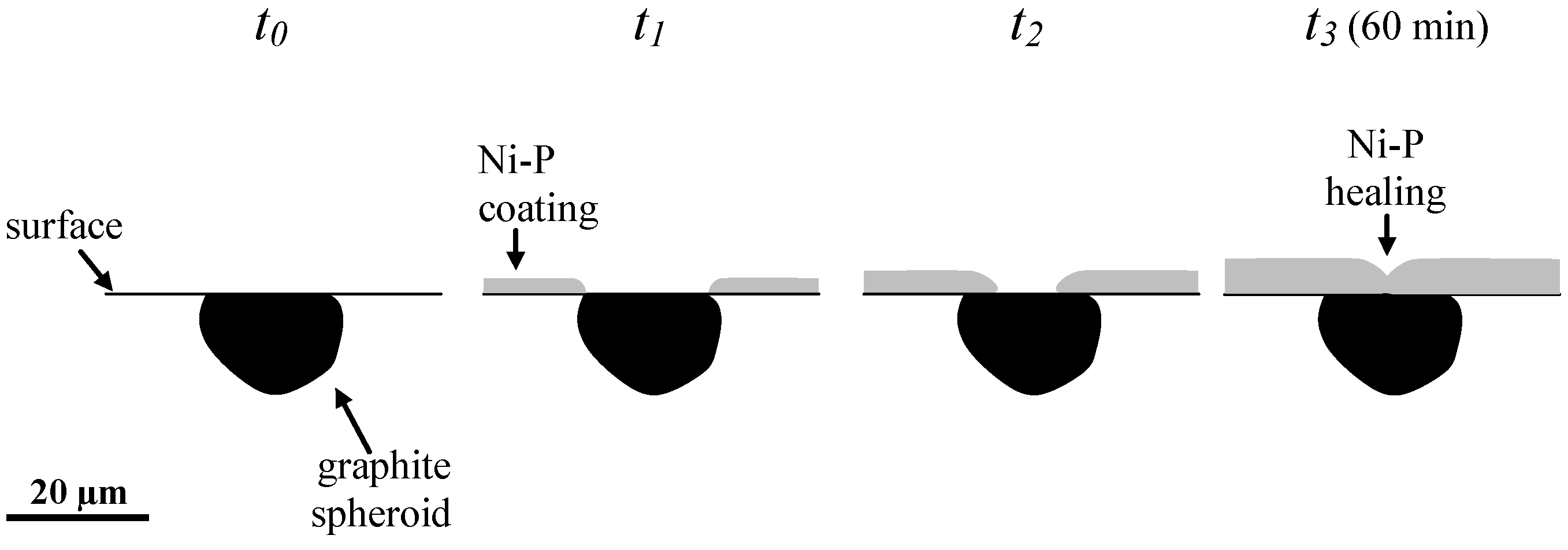
Figure 9.
Voltammogram of the SG cast iron at T = 10 °C (Tafel plot).

Figure 10.
Ni-P Coating obtained on the SG cast iron after a 5 min experiment, including two steps. Step one: 3 min of polarization (V). Step two: 2 min at T = 84 °C. (a) SEM top-view observation (BSE detector); (b) nickel EDX mapping analysis (kα = 7.47 eV); (c) phosphorus EDX mapping analysis (kα = 2.01 eV); and (d) cross-sectional-view observation (SE detector).


Table 1.
Chemical composition of the EN-GJS-500-7 cast iron in %.
| C | Si | Mn | Fe |
|---|---|---|---|
| 3.50–3.70 | 2.30–2.60 | max. 0.40 | bal. |
Table 2.
Nernst potentials, E (mV/SCE).
| Oxidation of Fe | Reduction of H+ | Reduction of Ni2+ |
|---|---|---|
| = −861 | = −589 | = −468 |
Note: E° is the standard potential and C the molar concentration of the chemical species.
© 2018 by the authors. Licensee MDPI, Basel, Switzerland. This article is an open access article distributed under the terms and conditions of the Creative Commons Attribution (CC BY) license (http://creativecommons.org/licenses/by/4.0/).
Share and Cite
MDPI and ACS Style
Forestier, I.; Berthomé, G.; Wouters, Y. Study of Electroless Nickel Coatings on EN-GJS-500-7 Spheroidal Graphite Cast Iron. Coatings 2018, 8, 239. https://doi.org/10.3390/coatings8070239
AMA Style
Forestier I, Berthomé G, Wouters Y. Study of Electroless Nickel Coatings on EN-GJS-500-7 Spheroidal Graphite Cast Iron. Coatings. 2018; 8(7):239. https://doi.org/10.3390/coatings8070239
Chicago/Turabian StyleForestier, Igor, Grégory Berthomé, and Yves Wouters. 2018. "Study of Electroless Nickel Coatings on EN-GJS-500-7 Spheroidal Graphite Cast Iron" Coatings 8, no. 7: 239. https://doi.org/10.3390/coatings8070239
Note that from the first issue of 2016, this journal uses article numbers instead of page numbers. See further details here.