
Angular Momentum of Leaky Modes in Hollow-Core Fibers


1
Prokhorov General Physics Institute of the Russian Academy of Sciences, 38 Vavilov Street, 119333 Moscow, Russia
2
Image Processing Systems Institute of the Russian Academy of Sciences—Branch of the FSRC “Crystallography and Photonics” RAS, 151 Molodogvardejskaya Street, 443001 Samara, Russia
*
Author to whom correspondence should be addressed.
Fibers 2022, 10(10), 92; https://doi.org/10.3390/fib10100092
Submission received: 16 September 2022
/
Revised: 13 October 2022
/
Accepted: 17 October 2022
/
Published: 21 October 2022
(This article belongs to the Collection Feature Papers in Fibers)
Abstract
:It is known that angular momentum (AM) is an important characteristic of light, which can be separated into the spin (SAM) and orbital parts (OAM). The dynamical properties of the spin and orbital angular momentums are determined by the polarization and spatial degrees of freedom of light. In addition to optical vortex beams possessing spatial polarization and phase singularities, optical fibers can be used to generate and propagate optical modes with the orbital and spin parts of the angular momentum. In this paper, using the example of hollow-core fibers, we demonstrate the fact that their leaky air core modes also have an orbital part of AM in the case of circular polarization arising from the spin–orbit interaction of the air core modes. The reason for the appearance of AM is the leakage of the air core mode energy.
1. Introduction
A careful analytic treatment of the electromagnetic field gives the total angular momentum (AM) of any light wave in terms of a sum of spin and orbital contributions [1]. The spin AM of light waves arises from the polarization state of a propagating light wave, and it is purely intrinsic, i.e., independent of the coordinate origin [2]. The orbital AM of a light wave originates from phase gradients and can have intrinsic and extrinsic parts [3]. The spin and orbital AM occur due to local energy flows and together constitute the Poynting vector. Vortex modes carrying AM can appear in vortex beams [4], cylindrical fibers [5] and metallic wires [6]. In this paper, we want to demonstrate AM and its orbital and spin components for leaky modes of hollow-core fibers based on Poynting vector (Abraham) formalism. The main reason for the emergence of AM for the air core modes of the hollow-core fibers is the outflow of their energy in the transverse direction and the spin–orbit interaction of the air core modes. The existence of the orbital part of the transverse component of the Poynting vector is not associated with the presence of a helicoidal phase front of the mode.
In our work [7], it was shown that the energy leakage of the core modes of hollow and solid core micro-structured optical fibers is accompanied by the formation of vortices in the transverse component of the Poynting vector of these modes. The streamlines of the transverse component of the Poynting vector of the core modes were calculated for elliptical polarization and had the shape of an unwinding spiral with the formation of vortex centers in the cladding elements. The centers of the vortices themselves were at the intersection points of the projections of the transverse component of the Poynting vector when . In this case, a certain configuration of the vortices of the transverse component of the Poynting vector of the air core fundamental mode in the cladding elements corresponded to the minimum loss of the hollow-core fiber.
Hollow-core fibers have attracted attention in recent years due to their potential to transmit radiation with losses lower than those in modern telecommunications fibers. In this case, we are talking about hollow-core fibers with negative curvature of the core–cladding boundary (NCHCFs) with a cladding consisting of several capillaries located on the support tube and an important subclass of these fibers. The use of a modified version of hollow-core fibers with additional cladding capillaries inserted into the main cladding capillaries led to a decrease in the level of losses at a wavelength of 1.55 µm to a level of 1 dB/km [8]. All these results were obtained using silica glass hollow-core fibers of a rather simple design and, in our opinion, their unique optical properties are determined by complex processes arising from the leakage of the air core modes energy.
The purpose of this work is to define the respective roles of the orbital and spin parts of the transverse component of the Poynting vector of the air core modes in forming the AM of these modes. Until now, the air core leaky modes have been considered from the point of view of orbital angular momentum (OAM modes) [9,10,11]. OAM modes can be obtained using the vector mode bases of hollow-core fibers. In this paper, we study the angular momentum and its spin and orbital parts for a single fundamental air core mode. Additionally, knowledge of the behavior spin and orbital parts of the transverse component of the Poynting vector allows us to determine their influence on the combined direction of the core mode energy current in the cross-section of the fiber. It has recently been demonstrated that the relative contributions of the spin and orbital parts are of prime importance depending on which part is more useful to the target application. In our case, the main goal is to determine the mechanism of AM formation of the air core modes in hollow-core leaky fibers when a transverse component of the Poynting vector is divided into spin and orbital parts.
2. SAM and OAM of the Fundamental Air Core Mode in Hollow-Core Fibers
As a simple example, let us consider SAM and OAM for the fundamental air core mode of silica glass capillary. Assuming harmonic time dependence for the electric and magnetic fields, light waves are considered to propagate in the z-direction:
where is a propagation constant of the air core mode, and is a circle frequency. The solution of the Helmholtz equation for axial components of electric and magnetic fields of the air core modes in separate geometric regions of the capillary looks like:
where , is a refractive index of the fiber geometric regions (i = 1, 2, 3), , is a capillary radius, is a thickness of the capillary wall, and are Bessel and Hankel functions, and A, B, C, and D are complex coefficients. The expressions for the axial component of magnetic field of the air core modes look similar but have other complex coefficients, and cosine is replaced by sine in (2) and vice versa. Using the known relations for the cylindrically symmetrical geometry of the capillary, one can find the transverse components of the air core mode fields from the above axial components:
Thus, using Equations (2) and (3) with known , one can obtain a time average value of the Poynting vector of the fundamental air core mode and, correspondingly, its kinetic (Abraham-type) z-component of angular momentum density , where , are the total electric and magnetic fields of the air core mode and is an azimuthal component of the Poyning vector.
On the other hand, according to [1], the transverse component of the Poynting vector can be decomposed into orbital and spin parts in terms of (total electric field of the capillary fundamental air core mode):
where c is the light velocity. The spin–orbital decomposition of AM is possible and physically meaningful, and in addition, the spin and orbital AM of light are separately observable in optics [6]. It is known that the spin AM is associated with light polarization, and right- or left-hand circular polarizations of the air core mode have helicities of different signs . As is shown below, the linearly polarized air core mode also has the spin AM, albeit a very small value due to the presence of energy leakage in the air core modes. The orbital AM of uniformly polarized paraxial beams is independent from polarization [12], as is shown below, and the value of OAM depends on the air core mode state polarization. The reason for this is the interaction of the air core mode radiation with the core–cladding boundary of the fiber and, as a consequence, the appearance of the spin–orbit interaction of the fundamental air core mode.
Let us consider the fields of the fundamental air core mode in cylindrical coordinates and . Then, from (4), it is possible to obtain the azimuthal components of the spin and orbital parts of the Poynting vector. Calculations of the azimuthal components of the spin part of the Poynting vector for linear and circular polarizations of the fundamental air core mode give the following expression:
Since the propagation constant is a complex number in leaky fibers, the spin part of transverse component of the Poynting vector is not equal to zero for both polarizations in (5). The azimuthal components of the orbital part of AM for the linearly and circularly polarized fundamental air core mode can be obtained from (4):
Based on Equations (2) and (3), it is seen that Expression (6) is equal to zero due to the fact that the dependence on ϕ is described by the real sine and cosine functions. This means that the AM of the capillary air core mode should be determined by the spin part of the transverse component of the Poynting vector with a density of .
The above results indicate that the leaky air core modes of the capillary should have AMs of a certain value. In order to calculate spin and orbital AMs for NCHCF, it is necessary to write the axial components of electric and magnetic fields of the air core mode (2) in the form of expansion in Fourier–Bessel series.
3. Results
In this section, we numerically calculate, using (4), the wavelength dependencies for spin and orbital AM for the single capillary with a core diameter of 20 µm and NCHCF with a core diameter of 17 µm and with the capillary wall thickness of 0.725 µm (Figure 1). In the case of NCHCF, we mean the thickness of the cladding capillary wall. The cladding of NCHCF consists of six capillaries with inner diameters of 8.5 µm. Both fibers are made of silica glass.
To calculate the spin AM of the fundamental air core mode, we used Matlab and Comsol Multiphysics. Here, it is worth clarifying that the fundamental air core mode is a hybrid mode of HE11 type (m = 1 in (2)) The axial component of the Poynting vector of circular polarized fundamental air core modes and their distributions of the transverse component of the Poynting vector for the capillary and the NCHCF are shown in Figure 2.
It is known that the loss dependence on wavelength for a capillary and NCHCF has a band structure, and waveguide losses increase with the decreasing air core diameter of the fibers.
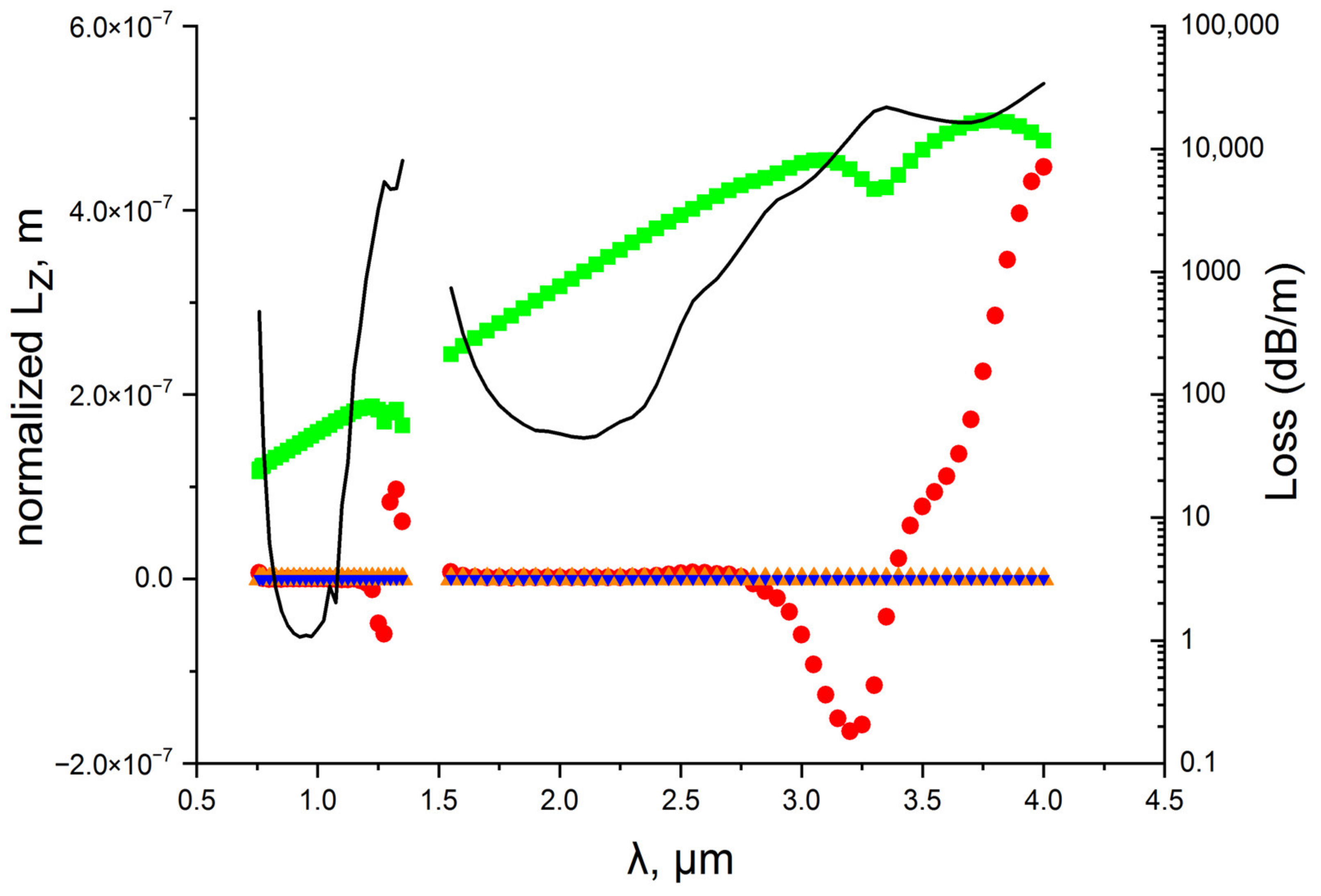
Our goal was to demonstrate the effect of losses of leaky hollow-core fibers on the values of the angular momentum of the fundamental air core mode and its parts (spin and orbital). For this, such values of the hollow-core fiber diameter were chosen that would provide a sufficiently high leakage loss level at least in long wavelength transmission bands. It should be noted that the material loss of silica glass in this case was much less than the leakage loss, and their influence can be neglected (about 1000 dB/m at wavelength of 4 µm). It was shown in [13] that the waveguide losses of leaky fibers are mainly determined by the orbital part of the transverse component of the Poynting vector because the orbital part has a non-zero radial component and zero value of the azimuthal component (6). Thus, the formation of AM of the fundamental air core mode should be determined by the spin part of the transverse component of the Poynting vector both in the case of linear and, especially, in the case of circular polarization (5). In order to demonstrate the effect of the spin part of the transverse component of the Poynting vector on AM formation in the capillary and NCHCF, two transmission bands were considered with high and lower loss level (Figure 3 and Figure 4). Figure 3 and Figure 4 show that the losses of optical fibers at wavelengths of 1 µm differ by two orders of magnitude. The positions of the boundaries of the transmission bands in hollow-core leaky fibers are well described by the ARROW model [14].
As can be seen from Figure 3, the wavelength dependence of spin AM for circular polarized fundamental air core mode behaves qualitatively in the same way in both transmission bands. Its value increases with increasing wavelength and loss level in the fibers. In the case of linear polarized mode, the value of spin AM is non—zero (5) but several orders of magnitude smaller than the spin AM for circular polarized mode. The monotonic increase in spin AM with wavelength is associated with an increase in effective area of the fundamental air core mode.
The value of orbital AM is very small in both transmission bands, but in the case of the circular polarization of the fundamental air core mode, its growth with wavelength is noticeable (Figure 3). In our opinion, this is due to the spin–orbit interaction of the air core mode that occurs at the core–cladding boundary. The mode radiation interacts more strongly with the capillary wall with an increase in the wavelength, which causes effects leading to spin–orbit coupling. The connection between the spin and orbital parts of the AM of the fundamental air core mode is also indicated by the fact that when changing from left-handed circular polarization to right-handed, the sign of changes. Figure 2 clearly shows that the transverse component of the Poynting vector of the fundamental air core mode is predominantly directed in azimuth direction, which also indicates that the spin part of the AM should make the main contribution to the formation of the total AM of the fundamental air core mode.
In order to compare the values of the spin and orbital AMs of the fundamental air core mode and the ones of the OAM mode localized on the principle of total internal reflection (ring modes of the capillary wall), we calculated the spin and orbital AMs for the ring OAM1,1 mode () of the capillary wall at the center of the first transmission band (Figure 3). It can be seen from Figure 3 that the value of the orbital AM of the OAM1,1 mode is comparable with the values of the spin AM of the fundamental air core mode and significantly exceeds the values of the orbital AM of this mode. In the case of NCHCF, the wavelength dependence of spin AM has monotonic wavelength dependence in both transmission bands (Figure 4) for circular polarized fundamental air core mode, but it has features (minimum) at the long wavelength edge of the transmission bands due to anti-crossing between the fundamental air core mode and the cladding mode. Anti-crossing leads to an increase in the air core mode losses at the long wavelength edge of the transmission bands and to an increase in the absolute value of the orbital AM. In our opinion, the orbital AM changes sign due to the fact that the energy of the fundamental air core mode flows into the cladding mode, which is leaky and has the opposite sign of . Its behavior correlates with the behavior of the spin AM, which indicates the presence of spin–orbit interaction in this spectral range at the core–cladding boundary. It is also worth noting that the orbital AM changes its sign in both cases (Figure 3 and Figure 4) with changes in the direction of rotation from left to right circular polarization.
4. Discussion
It is evident that the total AM of the leaky air core mode of the hollow-core fiber is determined by the polarization state of the air core mode. Spin AM comparable with the orbital AM of air core OAM1,1 mode can be obtained for the circular polarized fundamental air core mode of silica glass capillary and NCHCF. The occurrence of orbital AM for leaky modes of silica glass capillary arises from the air core mode energy leakage when there is an interaction between the core mode radiation and core–cladding boundary wall. This is especially pronounced in the long-wavelength transmission bands. The spin–orbit interaction of the leaky air core mode at the core–cladding boundary leads to the formation of an azimuthal component of the orbital part of the transverse component of the Poynting vector and correspondingly to . Thus, an increase in the value of the orbital AM of the fundamental air core mode of the capillary is only possible with an increase in leakage losses. A slightly different situation is observed for NCHCF with a more complex shape of the core–cladding boundary. In this case, orbital AM can occur due to anti-crossing between the air core mode and cladding mode with a certain type of discrete rotational symmetry. The value of spin AM also changes at the anti-crossing wavelengths, and the value of the orbital part of AM of the air core mode can reach the values comparable with the spin part and change sign. Thus, the main reasons for the appearance of orbital AM are a high loss level at the edges of the transmission bands and anti-crossing between the air core modes and the cladding modes. We believe that such a spectral behavior of the spin and orbital parts of AM of the air core modes is similar to all types of hollow-core fibers. Differences in their spectral behavior can arise due to the level of complexity of the cladding structure of one or another type of hollow-core fiber and, as a consequence, due to the spatial and spectral distribution of the cladding modes. These factors lead to the appearance of the spin–orbit interaction of the air core mode at the core–cladding boundary. It can be assumed that there are some approaches associated with changing geometric parameters of the leaky fibers or using new physical mechanisms when the orbital AM of the leaky modes can be increased not due to an increase in the waveguide losses of the fibers. We intend to make these studies the subject of our future work.
Author Contributions
Conceptualization, A.P.; methodology, G.A., S.S., V.K. and A.P.; software, G.A. and S.S.; validation, G.A., S.S., V.K. and A.P.; formal analysis, G.A., S.S., V.K. and A.P.; investigation, G.A., S.S. and A.P.; resources, G.A., S.S., V.K. and A.P.; data curation, G.A.; writing—original draft preparation, A.P.; writing—review and editing, G.A., S.S., V.K. and A.P.; visualization, G.A.; supervision, A.P.; project administration, A.P.; funding acquisition, A.P. All authors have read and agreed to the published version of the manuscript.
Funding
This research was funded by the Russian Science Foundation, grant number 22-22-00575.
Institutional Review Board Statement
Not applicable.
Informed Consent Statement
Not applicable.
Data Availability Statement
Data underlying the results presented in this paper may be obtained from the authors upon reasonable request.
Conflicts of Interest
The authors declare no conflict of interest.
References
- Berry, M.V. Optical currents. J. Opt. A Pure Appl. Opt. 2009, 11, 094001. [Google Scholar] [CrossRef]
- O’Neil, A.T.; MacVicar, I.; Allen, L.; Padgett, M.J. Intrinsic and Extrinsic Nature of the Orbital Angular Momentum of a Light Beam. Phys. Rev. Lett. 2002, 88, 053601. [Google Scholar] [CrossRef] [PubMed]
- Yao, A.M.; Padgett, M.J. Orbital angular momentum: Origins, behavior and applications. Adv. Opt. Photon. 2011, 3, 161–204. [Google Scholar] [CrossRef] [Green Version]
- Bai, Y.; Lv, H.; Fu, X.; Yang, Y. Vortex beam: Generation and detection of orbital angular momentum. Chin. Opt. Lett. 2022, 20, 012601. [Google Scholar] [CrossRef]
- Wang, Z.; Tu, J.; Gao, S.; Li, Z.; Yu, C.; Lu, C. Transmission and Generation of Orbital Angular Momentum Modes in Optical Fibers. Photonics 2021, 8, 246. [Google Scholar] [CrossRef]
- Picardi, M.F.; Bliokh, K.Y.; Rodriguez-Fortuno, F.J.; Alpeggiani, F.; Nori, F. Angular momenta, helicity, and other properties of dielectric—Fiber and metallic—Wire modes. Optica 2018, 5, 1016–1026. [Google Scholar] [CrossRef] [Green Version]
- Pryamikov, A.; Alagashev, G.; Falkovich, G.; Turitsyn, S. Light transport and vortex—Supported wave—Guiding in micro—Structured optical fibres. Sci. Rep. 2020, 10, 2507. [Google Scholar] [CrossRef] [PubMed] [Green Version]
- Hecht, J. Hollow—Core fiber at OFC 2021: Optimizing for applications and ruggedness. Laser Focus World 2021, 6, 9–11. [Google Scholar]
- Li, H.; Ren, G.; Lian, Y.; Zhu, B.; Tang, M.; Zhao, Y.; Jian, S. Broadband orbital angular momentum transmission using a hollow—Core photonic bandgap fiber. Opt. Lett. 2016, 41, 3591–3594. [Google Scholar] [CrossRef] [PubMed]
- Li, H.; Ren, G.; Zhu, B.; Gao, Y.; Yin, B.; Wang, J.; Jian, S. Guiding terahertz orbital angular momentum beams in multimode Kagome hollow—Core fibers. Opt. Lett. 2017, 42, 179–182. [Google Scholar] [CrossRef] [PubMed]
- Sharif, V.; Pakarzadeh, H. Terahertz hollow—Core optical fibers for efficient transmission of orbital angular momentum modes. J. Light. Technol. 2021, 39, 4462–4468. [Google Scholar] [CrossRef]
- Bliokh, K.; Nori, F. Transverse and longitudinal angular momenta of light. Phys. Rep. 2015, 592, 1–38. [Google Scholar] [CrossRef] [Green Version]
- Alagashev, G.K.; Stafeev, S.S.; Kotlyar, V.V.; Pryamikov, A.D. The effect of the spin and orbital parts of the Poynting vector on light localization in solid core microstructured optical fibers. Photonics 2022. submitted. [Google Scholar] [CrossRef]
- Litchinitser, N.M.; Dunn, S.C.; Usner, B.; Eggleton, B.J.; White, T.P.; McPhedran, R.C.; Martijn de Sterke, C. Resonances in microstructured optical fibers. Opt. Express 2003, 11, 1243–1251. [Google Scholar] [CrossRef]
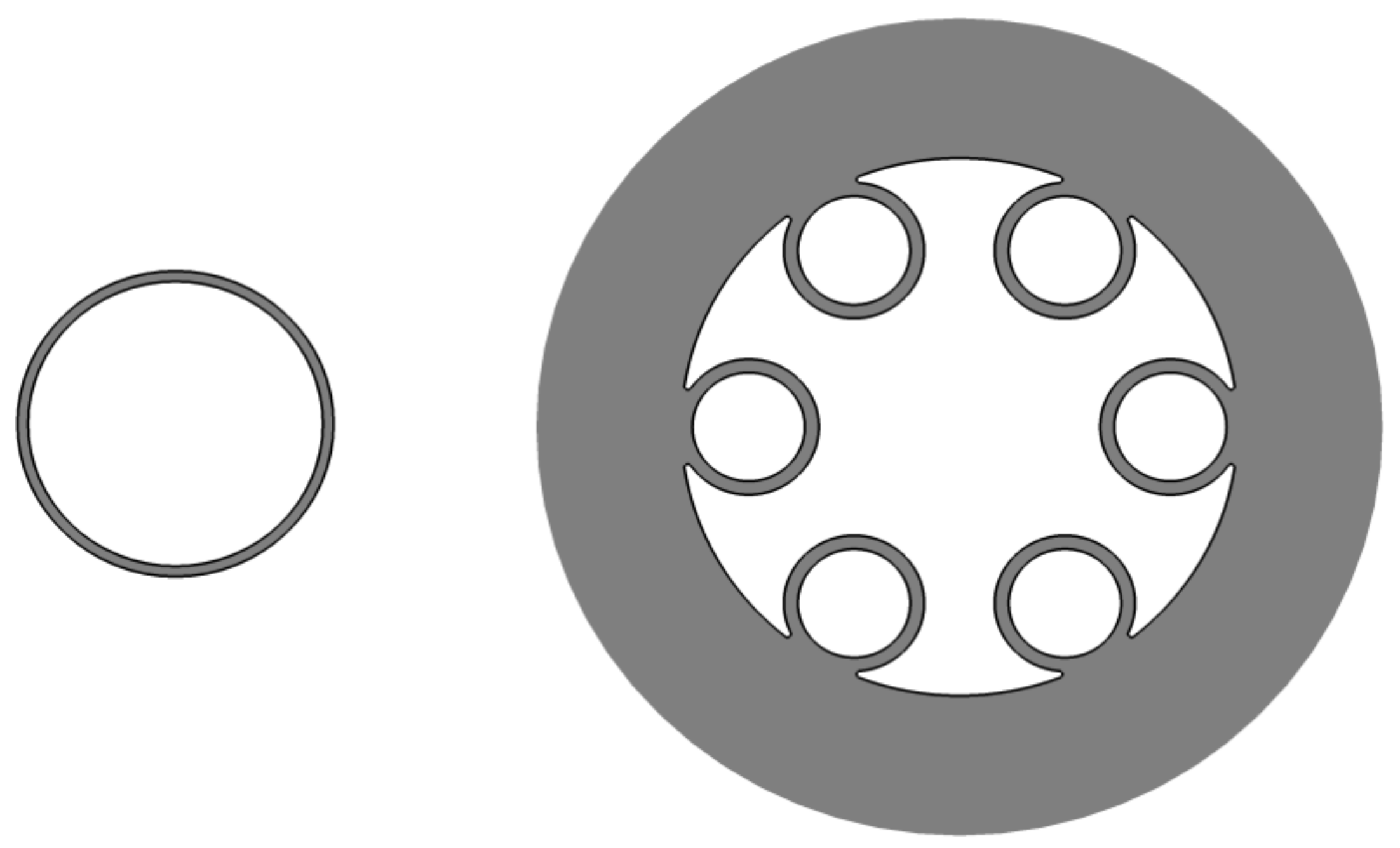
Figure 1.
Cross section of the single capillary (left) and NCHCF (right) described in the text.

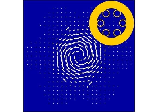
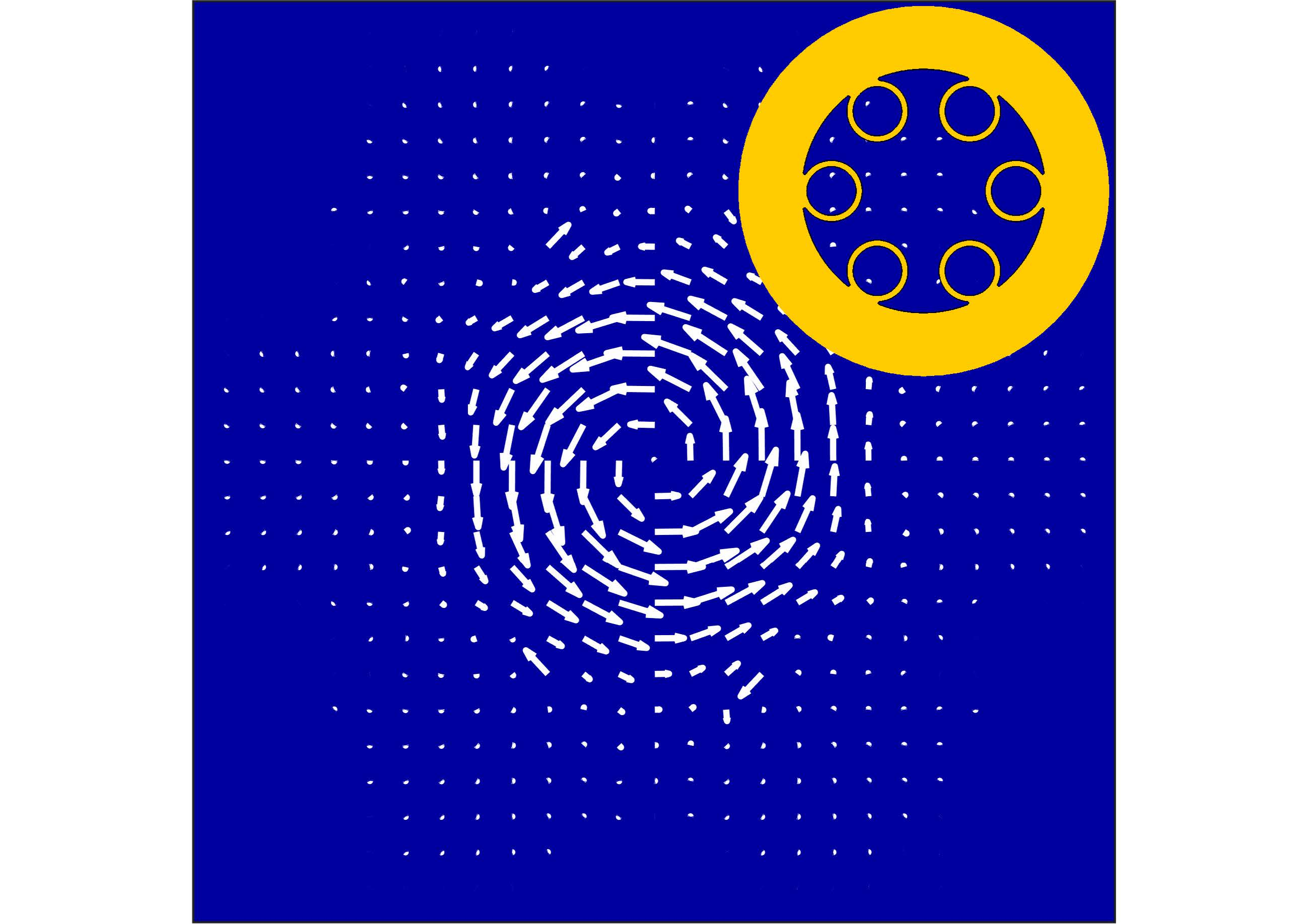
Figure 2.
Axial components of the Poynting vector of circular polarized air core fundamental modes for the capillary (left) and NCHCF (right) described in the text. The arrows show the distribution of transverse component of the Poynting vector of these modes. Axial component of the Poynting vector is normalized to the input power 1 W. The wavelength is 2 µm.

Figure 3.
Wavelength dependence of spin AM (green—circular polarization and orange—linear polarization) and orbital AM (red—circular polarization and blue—linear polarization) for fundamental air core mode of the capillary described in the text. The solid black line is loss dependence for two transmission bands. It is assumed that AM is normalized to the input power of 1 W. The point with yellow color indicates the value of spin AM for OAM1,1 mode of the capillary wall; the point with dark yellow indicates the value of orbital AM.

Figure 4.
Wavelength dependence of spin AM (green—circular polarization and orange—linear polarization) and orbital AM (red—circular polarization and blue—linear polarization) for fundamental air core mode of the NCHCF described in the text. The solid black line is loss dependence for two transmission bands. It is assumed that AM is normalized to the input power of 1 W.

Publisher’s Note: MDPI stays neutral with regard to jurisdictional claims in published maps and institutional affiliations. |
© 2022 by the authors. Licensee MDPI, Basel, Switzerland. This article is an open access article distributed under the terms and conditions of the Creative Commons Attribution (CC BY) license (https://creativecommons.org/licenses/by/4.0/).
Share and Cite
MDPI and ACS Style
Alagashev, G.; Stafeev, S.; Kotlyar, V.; Pryamikov, A. Angular Momentum of Leaky Modes in Hollow-Core Fibers. Fibers 2022, 10, 92. https://doi.org/10.3390/fib10100092
AMA Style
Alagashev G, Stafeev S, Kotlyar V, Pryamikov A. Angular Momentum of Leaky Modes in Hollow-Core Fibers. Fibers. 2022; 10(10):92. https://doi.org/10.3390/fib10100092
Chicago/Turabian StyleAlagashev, Grigory, Sergey Stafeev, Victor Kotlyar, and Andrey Pryamikov. 2022. "Angular Momentum of Leaky Modes in Hollow-Core Fibers" Fibers 10, no. 10: 92. https://doi.org/10.3390/fib10100092
Note that from the first issue of 2016, this journal uses article numbers instead of page numbers. See further details here.