1. Introduction
Carbon fiber properties are directly dependent on the quality of the precursor fiber [
1,
2,
3]. Carbon fiber modulus has been shown to be directly proportional to the polyacrylonitrile (PAN) precursor modulus [
4]. As a result, careful control of precursor properties is necessary. It has been shown that precursor fibers with non-round cross-section cannot withstand a high draw ratio during subsequent spinning, stabilization, and carbonization due to stress concentration [
5]. Circular fibers, on the other hand, experience a homogeneous Poisson’s contraction when exposed to tensile forces [
6]. Tsai found that the shape of the cross-section is one of the most important characteristics of fibers, with deviation from circularity affecting luster, mechanical, and other physical properties [
6].
Achievement of a circular cross section is largely determined by controlling the relative diffusion of solvent out and non-solvent in the filaments during coagulation. When the flux of solvent outward is less than the inward flux, the filament swells and a circular cross-section can be expected. This swelling occurs at high coagulation bath temperatures and high solvent content in the coagulating bath [
6]. For this reason, cross sections are characteristically round at 50 °C or above. However, high bath temperatures have also been attributed to an increase in void content and subsequent decrease in fiber density, resulting in poor fiber properties [
2,
3,
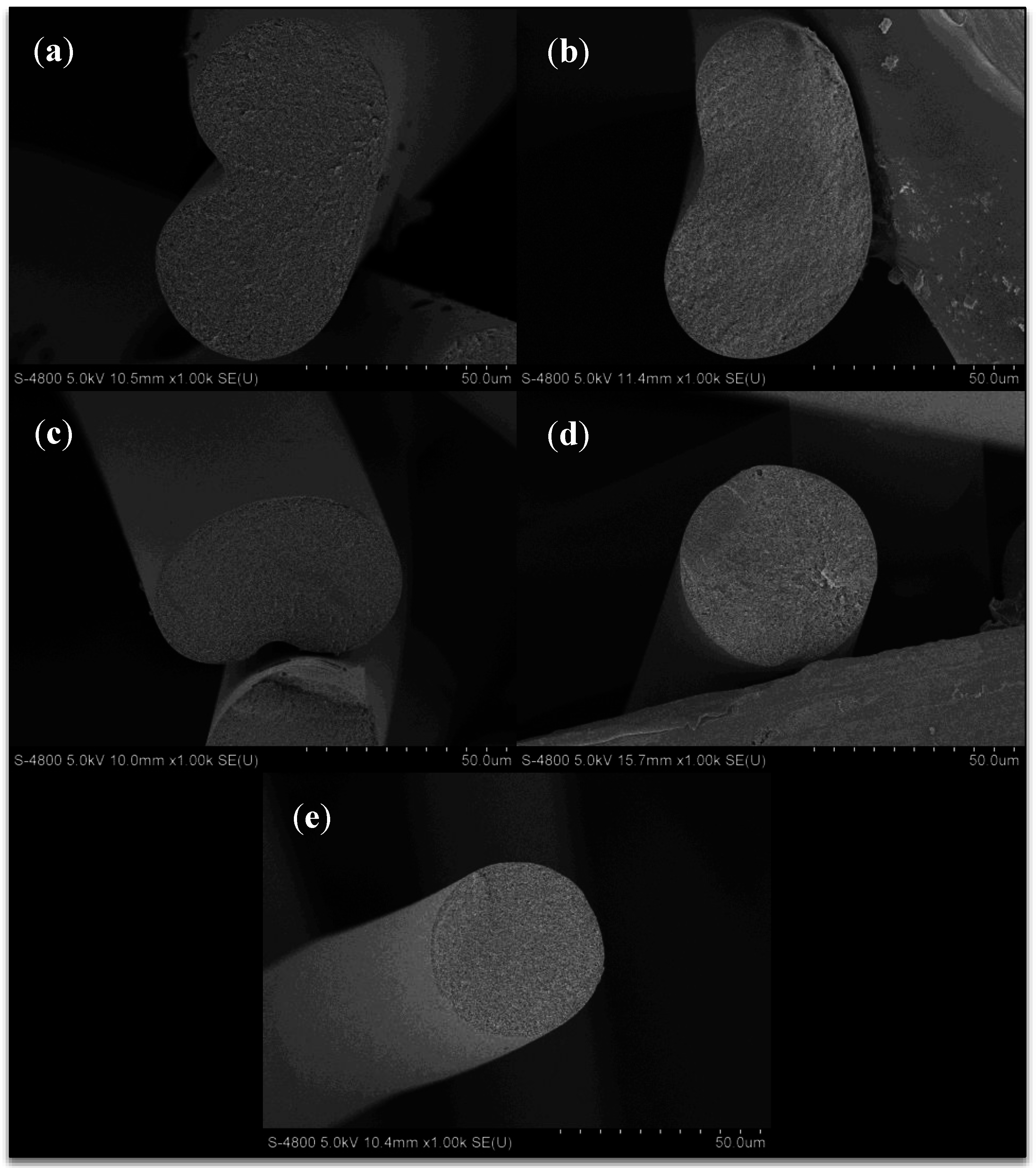
7]. An example of a PAN fiber spun into a high temperature coagulation bath (60 °C) is shown in
Figure 1. Although circular in cross sectional shape, large macrovoids are evident.
Figure 1.
Example of a polyacrylonitrile (PAN) fiber spun at high coagulation bath temperature (60 °C), containing macrovoids.
Figure 1.
Example of a polyacrylonitrile (PAN) fiber spun at high coagulation bath temperature (60 °C), containing macrovoids.
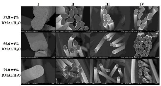
In contrast, at lower coagulation temperatures and typical solvent concentrations (<70 wt%), the outward diffusion of solvent dominates, but the perimeter of the filament in contact with non-solvent is solidified early. As outward diffusion of solvent continues, the filament collapses, resulting in non-round (often bean-shaped) cross-sectional shape [
3,
5,
8].
Due to the difficulties in achieving a round, dense cross-section fiber, numerous researchers have investigated the effect of coagulation bath composition on the resulting fiber. Few, if any, have focused on high solvent concentrations in the coagulation bath (>70 wt% solvent/non-solvent), with chilled coagulation bath temperature, and its effect on the resulting fiber. Multiple authors have studied bath concentrations up to 70 wt% [
2,
3,
6,
8,
9,
10,
11]. Many of these authors were spinning at elevated bath temperatures (>20 °C). As a result, they were often unable to attain void-free round fibers.
Unique to this research effort, the results gathered here were produced on a small pilot scale (0.5 k filament, continuous tow), with industrially relevant filament diameters, and all samples were collected throughout the course of a single spin run. Sampling from a single run limited changes to spinning variables which may be present in data collected during various runs, with differing spinning solutions, environmental factors, etc. Here, a systematic study of coagulation bath composition, at high solvent composition and low bath temperature is reported. The resulting fiber shape, density, orientation, and tensile properties at varying points in the spinning process are discussed.
2. Experimental Section
2.1. Materials
Polyacrylonitrile-co-methyl acrylate (PAN-co-MA) polymer from Scientific Polymer Products (catalog number 665) and reagent grade N,N-Dimethylacetamide (DMAc) from Fisher Chemical (Pittsburg, PA, USA) were used. Deionized water was used as the non-solvent.
2.2. Fiber Spinning
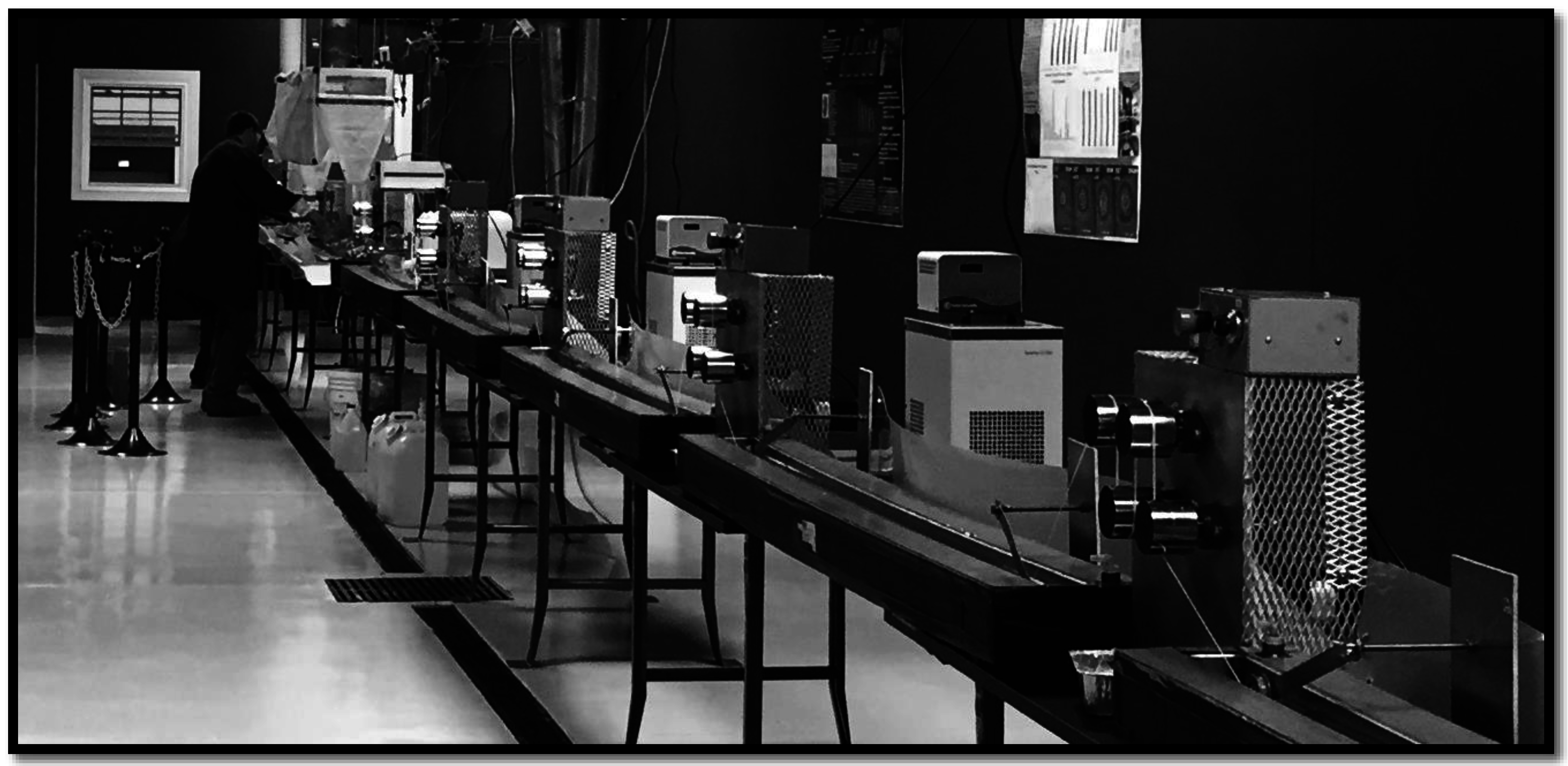
All fibers were spun utilizing the multifilament solution spinning facility at the University of Kentucky Center for Applied Energy Research (UKY CAER) (
Figure 2). A 23 wt% solution of PAN-co-MA/DMAc was prepared, deaerated, filtered, and solution spun into a DMAc/H
2O coagulation bath using a 500 filament wet-jet spinnerette with 60 µm capillary diameters. All fibers presented in this study were spun during a single 5-hour spinning run. The only variable allowed was the concentration of solvent to water in the coagulation bath. The initial bath concentration, as measured by calibrated refractive index, was 79.0 wt% DMAc/H
2O. Wet-jet solution spinning at >80 wt% solvent in the coagulation bath was previously found to be marginally effective at coagulating or demixing the polymer dope jets in a timely manner, and resulted in excessively fragile and viscous proto-filaments. Therefore, this was determined to be the upper limit in solvent concentration for the given system. After achieving spinning stability, samples were collected at various points along the spinline, shown in
Figure 3.
Following sample collection at a given bath concentration, a calculated mass of solution was pumped from the coagulation bath into a collection container and replaced with a calculated mass of pure deionized water to dilute the bath, defining the bath concentration for the subsequent fiber sampling,
etc. Each new coagulation bath solution was mixed thoroughly using an in-bath stirring system, until no further evidence of water-solvent dissolution was observed and the bath temperature was stable. For all samples, the coagulation bath temperature was held chilled to 19 ± 1.4 °C and fiber residence time within the coagulation bath was 87 s, with a calculated extrudate jet velocity of 1.3 m/min (not corrected for viscoelastic die swell), a take-up velocity of 0.9 m/min out of the coagulation bath, and a path length of 1.3 m. Excess heat of mixing from DMAc and water was dissipated using a circulating water/glycol external bath (heat sink). In addition, while five coagulation bath concentrations were studied, only three of the five coagulation conditions were studied down the entirety of the line, shown in
Table 1.
Figure 2.
Solution spinning line at the University of Kentucky Center for Applied Energy Research (UKY CAER).
Figure 2.
Solution spinning line at the University of Kentucky Center for Applied Energy Research (UKY CAER).
Figure 3.
Schematic of the solution spinning line at the UKY CAER, labeled with sampling points (I–IV). (I) After coagulation; (II) after washing; (III) after hot stretching; (IV) on the traversing takeup.
Figure 3.
Schematic of the solution spinning line at the UKY CAER, labeled with sampling points (I–IV). (I) After coagulation; (II) after washing; (III) after hot stretching; (IV) on the traversing takeup.
Table 1.
Locations of fiber sample collections along the spinline at various coagulation bath concentrations.
Table 1.
Locations of fiber sample collections along the spinline at various coagulation bath concentrations.
| Coagulation Bath Concentration (wt% DMAc/H2O) | Locations of Fiber Sample Collection |
|---|
| I | II | III | IV |
|---|
| 57.8 | ✓ | ✓ | ✓ | ✓ |
| 62.1 | ✓ | | | |
| 66.6 | ✓ | ✓ | ✓ | ✓ |
| 72.2 | ✓ | | | |
| 79.0 | ✓ | ✓ | ✓ | ✓ |
Following the coagulation bath, the tow was passed through a series of ambient temperature wash baths and hot stretching baths prior to spin finish application, drying, and take-up using a traversing winder. The draw down ratio is defined as the ratio of the tow velocities, exiting-to-entering the zone of interest. The spin draw (sampling point I), or draw applied during coagulation, calculated from the apparent entering and exiting velocities, was less than 1, which has been observed by others [
12,
13,
14,
15,
16,
17]. The tow velocity entering coagulation was calculated using the known, constant volumetric flow rate of the dope, and the dimension of the spinneret, and was used, uncorrected for viscoelastic die swell of the extruded jets, for the velocity calculation. Therefore, spin draw less than one did not necessarily indicate a tow shrinkage in the coagulation bath. Throughout the spin run the volumetric flow rate of the dope and take-up velocity out of the coagulation bath remained constant. The draw down ratios (stretch) applied at points I, II, III, and IV were 0.67×, 2.20×, 3.06×, and 1.07×, respectively, totaling 4.83×. The tow experiences a “gel draw” of 2.20× in the first wash bath, as the tow still contains enough solvent to plasticize the fibers. No stretch is applied to the fibers in the remaining wash baths. The largest draw (3.06×) occurred in the stretching baths (III). Here, the solidified, washed fiber was heated above its glass transition to 160 °C, allowing for stretch and collapse of intra-filament porosity. Again, the total draw experienced by the as-spun fiber was 4.83×.
2.3. Refractive Index
The coagulation bath concentrations were verified using a digital bench-top refractometer (RX-5000, Atago, Bellevue, NE, USA). A calibration curve for DMAc/H
2O solutions was determined, shown in
Figure 4. For concentrations from 0 wt% to 65 wt% DMAc/H
2O, there was a linear trend (
R2 = 0.99). However, from 65 wt% to 100 wt% DMAc/H
2O, the calibration curve produced a polynomial trend line (
R2 = 0.98). These trends, and the measured refractive index from each of the bath concentrations, were used to determine the exact bath concentration at each of the fiber coagulation conditions.
Figure 4.
Calibration curve developed using the refractive index for DMAc/H2O solutions.
Figure 4.
Calibration curve developed using the refractive index for DMAc/H2O solutions.
2.4. Freeze Drying
Fibers sampled from zones I–III were freeze-dried to preserve the uncollapsed fiber structure by first washing the collected, undried fiber in deionized water for the removal of excess solvent (as-spun fibers (zone IV) did not require freeze-drying, as the fibers at this point were collapsed and dried prior to takeup). The freeze-drying unit was chilled to −75 °C using liquid nitrogen. Following removal of solvent, the fibers were placed in the chilled freeze dryer, sealed, and subject to vacuum to reduce the pressure below the triple point of water (611.73 Pa, 273.16 K). While maintaining pressure below 611.73 Pa, as monitored with a thermocouple pressure gauge, the unit was allowed to slowly warm to room temperature over several hours following evaporation of the liquid nitrogen. Samples were removed when room temperature was achieved.
2.5. Fiber Sectioning
Following freeze-drying, fibers were sectioned to observe the cross section and structure using a Shandon Cryotome FSE (Themo Fisher Scientific, Kalamazoo, MI, USA). Fiber bundles were embedded in Tissue-Tek OCT compound (Sakura Finetek USA, Inc., Torrance, CA, USA) and cooled to −27 °C to harden the matrix compound. With the specimen at −27 °C and the chamber at −25 °C, the sample was trimmed with a microtome blade perpendicular to the fiber axis to achieve a clean cut, without pinching or altering the fiber cross-sections. The cut fibers were then washed in room temperature deionized water for removal of the matrix compound. Coag fibers, or fibers collected directly from the coagulation bath, were suitably brittle, following freeze-drying, to be pull-fractured under liquid nitrogen. Pull-fracturing coag fiber in this manner preserved the intra-filament fibrillar and void structure, which can be damaged by the microtome.
2.6. Scanning Electron Microscopy (SEM)
Imaging of the filament surface and cross sectional morphology was performed using a Hitachi S-4800 field emission SEM (Hitachi High-Technologies Corporation, Tokyo, Japan). Samples were sputter-coated with gold for 120 s using a Hummer 6.2 Sputter System (Anatech USA, Union City, CA, USA) using a sputtering current of 20 mA. For cross section observation, the previously microtomed fiber bundles were positioned vertically in a thin specimen split mount SEM sample holder (Ted Pella, Redding, CA, USA). Fibers were imaged with a 5 kV accelerating voltage and a 10 μA beam current, using the secondary electron detector (Hitachi High-Technologies Corporation, Tokyo, Japan). SEM digital image analysis, including cross sectional area and perimeter (for fiber diameter calculation), was done using Adobe Photoshop CS6 (Adobe, San Jose, CA, USA).
2.7. Wide-Angle X-Ray Diffraction (WAXD)
A Rigaku Smartlab 1 kW X-ray diffraction system (Rigaku Corporation, Tokyo, Japan) providing Ni-filtered CuKα radiation (λ = 1.54 Å) as the source and an operational voltage of 40 kV and current of 44 mA was used to measure the crystalline-related properties and orientation of the fibers. A Rigaku αβ-stage attachment (Rigaku Corporation, Tokyo, Japan) was used to investigate the 360-degree azimuthal circle, allowing the fiber axis to be rotated 360 degrees around the vertical. A step width of 0.2° at 5°/min was used for the azimuthal scan from −90 to 270°. Multi-filament tows were aligned perpendicular to the incident X-ray beam as carefully as possible, although some overlap of filaments could not be avoided (causing slight asymmetry in azimuthal peaks). The diffracted X-ray intensity data was analyzed using PDXL 2.0 software (Rigaku Corporation, Tokyo, Japan), and peaks were fit using a split pseudo-Voigt function. Data was smoothed using B-spline smoothing (chi = 1.50). The Herman’s orientation factor,
fc, was determined from the corrected azimuthal intensity distribution from the (
100) reflection (2θ = 16.9°), using Equations (1) and (2):
where
is the azimuthal angle and
is the scattered intensity along the angle
. The Herman’s orientation factor has the value of unity when the normal of the reflection plane is parallel to the reference direction and a value of −0.5 when the normal is perpendicular to the reference direction. A value of zero occurs when there is completely random orientation. The crystal size (
) and
d-spacing were calculated using Equation (3) (the Scherrer equation) and Equation (4) (the Bragg equation), respectively:
where
is the apparatus constant (0.94) and
is the
FWHM. Corrections for instrumental broadening were neglected in the calculation.
2.8. Tensile Property Analysis
Tensile properties of fiber samples were measured using ≥20 specimens per sample at a crosshead speed of 5 mm/min. The specimens were prepared by bonding a single filament to a 20 mm gauge length aperture card using Easypoxy K-20 (Cytec, Woodland Park, CO, USA). Following curing of the epoxy, the aperture card was mounted in miniature tensile grips of an MTS Systems Q10 machine (MTS, Eden Prairie, MN, USA) fitted with a 150 g load cell. The sides of the aperture card were then cut, leaving the filament intact.
4. Conclusions
A systematic study of the effects of coagulation bath composition, at relatively high solvent-to-water composition and low bath temperature, is reported using a small pilot scale solution spinning process (0.5 k filament, continuous tow), with industrially relevant filament diameters, for PAN precursor fibers. The results indicated numerous advantages of using a high solvent content (79.0 wt% DMAc/H2O) coagulation bath to achieve optimum fiber properties, when compared to fibers produced using a lower solvent composition bath. Higher coagulation bath solvent composition produced fibers that were more circular in cross section, smaller in diameter, higher in density, achieved an overall higher orientation (fc = 0.423, FWHM = 27.73), and produced fibers with higher break stress and modulus. In addition, it was observed that the fiber shape and cross sectional area set by the coagulation bath composition persisted down the entirety of the spinline. Larger bean shaped filaments spun using a lower (57.8 wt%) solvent concentration bath never reached the smaller diameter of those spun into the 79.0 wt% concentration bath, in spite of both experiencing the exact same draw ratios. Due to all of these observations, the importance of understanding the coagulation bath composition effect on the final fiber cannot be overstated, and is necessary to achieve optimum fiber performance.


