Article

Investigation on Strengthening Approaches Adopted for Poorly Detailed RC Corbels

1
Shimizu Corporation, International Division, Singapore 339509, Singapore
2
Institute of Industrial Science, The University of Tokyo, Tokyo 153-8505, Japan
*
Author to whom correspondence should be addressed.
Fibers 2017, 5(2), 16; https://doi.org/10.3390/fib5020016
Submission received: 19 February 2017 / Revised: 10 April 2017 / Accepted: 21 April 2017 / Published: 1 May 2017

Abstract

:
Poor detailing of the position of bearing pad over reinforced concrete (RC) corbel may lead to premature failure, which is undesired and structurally vulnerable. An appropriate retrofitting solution is necessary to ensure the functionality of such RC corbels. Considering the growing popularity of external carbon fiber-reinforced polymer (CFRP) in retrofitting, this research examines the effectiveness of an externally wrapped unidirectional CFRP sheet and compares its performance against traditional retrofitting methods. Moreover, it is intended to fulfill the lack of extensive research on external CFRP application for corbel strengthening. A total of eight medium-scale corbel specimens were tested on vertical load. Observed premature failure due to placing the bearing pad near the edge of corbel was verified and the effectiveness of the proposed structural strengthening solutions was studied. Experimental results show that although the loading capacity of the damaged corbel due to the poor detailing of bearing pad position could not be fully recovered, the external CFRP wrapping method demonstrated superior performance over RC jacketing and was able to prevent localized failure. Further study based on non-linear 3D finite element analysis (FEA) was carried out to identify the governing parameters of each retrofitting solution. Numerical studies suggested important parameters of various retrofitting alternatives for higher capacity assurance.

1. Introduction

Various design codes [1,2] have provided guidelines regarding detailing requirement for the position of a bearing pad above a corbel. It is recommended that the outer edge of the bearing pad should not be placed beyond the straight portion of the main tension steel bars of the corbel, and furthermore, the depth of the corbel at the corresponding position should never be less than half of its depth at the base. These provisions are provided to prevent premature local failure and ensure the desired capacity and performance of the corbels. If such minor detailing is overlooked in construction, it may lead to unsatisfactory structural performance. In a field study, several corbels were found to be locally failed by shallow splitting of concrete due to cracks inclined outwards of the corbel to meet the slope portion of the corbel as shown in Figure 1. Kriz and Raths [3] described this as the secondary modes of failure which don’t involve the deepest section of the corbel at the column face. Such failure is noticed at considerably lower load than the corresponding design value due to the poor detailing of the bearing pad position.
Such localized failure in a corbel is the target in this research, with comprehensive study on the parameters that govern the behavior of the selected retrofitting solutions. Meanwhile, once non-conformance occurs, available simplified formulas are not adequate to depict the real behavior of corbels. Therefore, along with the extensive experimental study, the necessity of the 3D analysis was realized.
Recently, the use of high strength carbon fiber–reinforced polymer (CFRP) has become popular for strengthening existing RC structures because of its high strength, long-term performance, ease of site handling, and light weight. FRP application has been experimentally verified to be effective in improving the shear and flexural capacity in a beam and a slab [4] and ductility in a column due to the confinement offered by FRP wrap [5]. In addition, the application of horizontal CFRP laminates has been proved to be effective in shear strengthening of deep beams with lower shear span to depth ratio, which are designed on similar principle as corbels though CFRP effectiveness will greatly vary depending upon shear span to depth ratio and fiber orientation [6]. Considering the CFRP effectiveness on the shear, flexural, and confinement improvement that forms the overall behavior of the corbel, CFRP will be one of the methods of rectifying corbels subjected to local failure criterion. However, while using external CFRP wrapping to address such case, the major consideration has not been available due to the lack of extensive researches. Among very few studies, experimental research conducted by Campione et al. [7] investigated the effectiveness of external CFRP wrapping on the ultimate strength of the corbel. Even though it was aimed to address the reinforcement congestion problem in an RC corbel by replacing the shear reinforcement by the external CFRP wrapping, 23.84% enhancement in the ultimate loading capacity was reported. Since the test was done in the absence of shear reinforcement, the behavior and effectiveness of the external CFRP wrapping may differ in the presence of the shear reinforcement. Elgwady et al. [8] have shown that CFRP can enhance the corbel capacity when the CFRP is adequately arranged. It was reported that the use of CFRP can increase the ultimate loading capacity of the corbel by 70%. Furthermore, Shadhan and Kadhim [9] showed that the ultimate loading capacity of the corbel can be enhanced up to 71% when the corbel is strengthened by CFRP. However, the corbels were loaded on the straight portion of the main tension steel bars of the corbel and the localized failure which is the main interest in this study did not occur.
There were two ultimate aims in this research. The first was to examine the residual capacity of the locally damaged corbel, and the second was to investigate the effectiveness and behavior of the external CFRP wrapping for retrofitting the locally damaged corbel. In the first stage of this study, the observed failure mode at the field study was experimentally replicated by introducing similar boundary condition and the residual capacity of the locally damaged corbel was further investigated through both experimental observation and numerical simulation. In the second stage, further experiments were conducted on CFRP retrofitted corbels with various numbers of CFRP layers and wrapping techniques. In order to have a better comparison with CFRP retrofitted methods, another series of corbel with RC jacketing was tested. Numerical simulation using non-linear 3D finite element analysis was conducted to verify the behavior through the study of principal strain contour and to study governing parameters for retrofitting implications. The simulation results were compared with the experimental results.

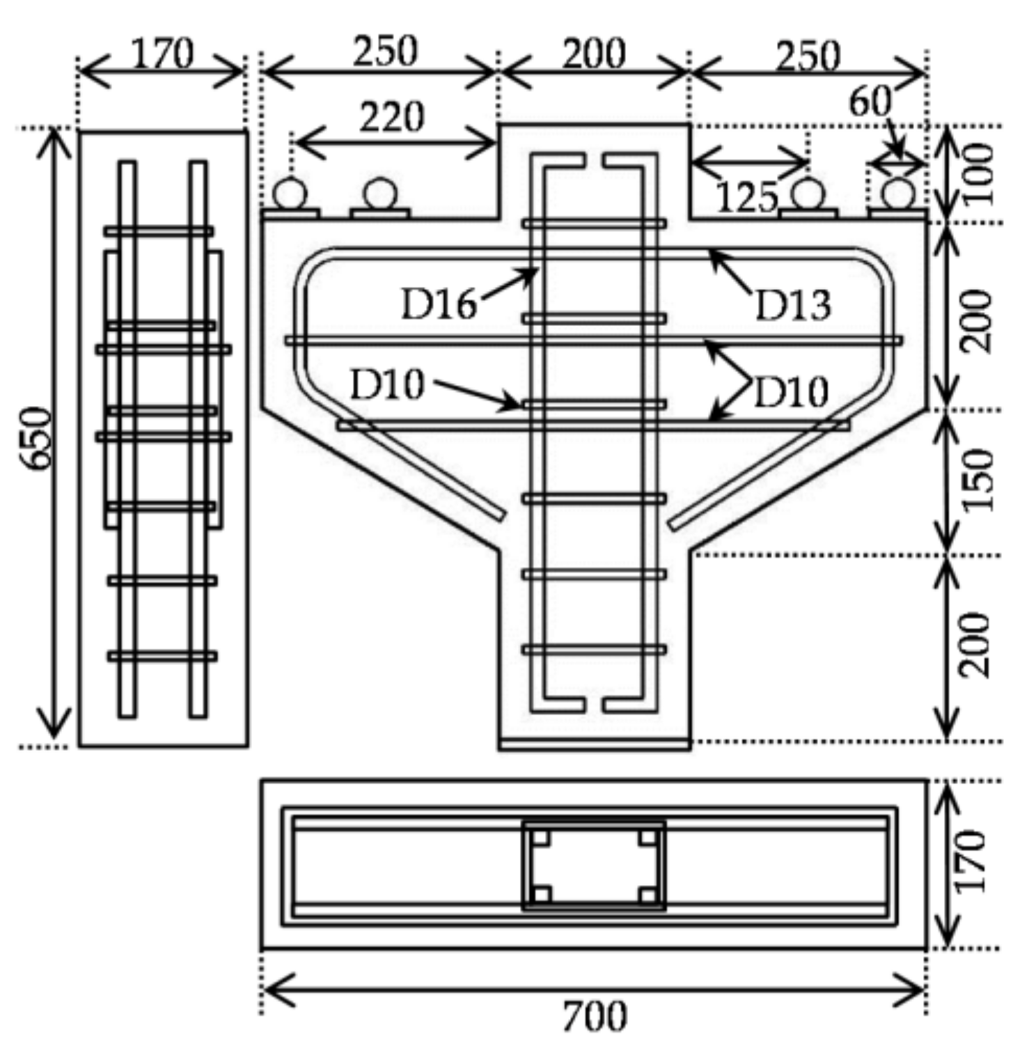
2. Experimental Program

2.1. Overview

A total of eight medium sized identical corbel specimens (listed in Table 1) were prepared to be tested on the vertical load. In the experiment, the column size was reduced and the width of the corbels was half of that of the corbel in the field study, but the cantilever projection length and height of the corbel were the same as those of the corbel in the field study where the corbel was used to support a beam or a slab in an industrial building, as shown in Figure 1. Each specimen consisted of a 650 mm length of column with two corbels projecting from the column in a symmetrical fashion, as shown in Figure 2. Corbels had cantilever projection length of 250 mm, with height of 350 mm and 200 mm at the face of the column and at the free end, respectively. The thickness of the specimen was 170 mm. In all cases, shear span to depth ratio less than unity was maintained. In all specimens, the main flexural bar of ϕ-13 mm was bent so that horizontal stirrups can be supported. The horizontal stirrup (ϕ-10 mm) provided both in corbel and column was at the pitch of 100 mm. All steel bars were deformed bars. Bearing pad used was of mild steel, having a thickness of 20 mm.
The experimental study was divided into three series. The first series was intended to verify the reason behind the local failure criterion and assess its residual capacity. The second and third series were retrofitting series. The objective of the second and third series was to quantify the effectiveness of various external CFRP wrapping and RC jacketing, respectively. In the first series, three RC corbel specimens were considered, signified by D-C, PE-C, and ResCap-PE-C. D-C was used as the control specimen with the reinforcement designed and detailed according to ACI 318 code [1]. The specimen was expected to behave in a ductile manner. In the case of PE-C, the bearing pad was shifted to the edge of the corbel in order to replicate the premature failure behavior observed in the field study. After being damaged, PE-C was loaded further by repositioning the bearing pad at its designed position. The specimen was signified as ResCap-PE-C in order to assess the residual capacity of locally failed corbels. The specimens in the first series are shown in Figure 3.
The retrofitting series was divided into CFRP retrofitting and RC jacketing. There were four RC corbel specimens in the second series (CFRP retrofitting), CFRP-CF-2L, CFRP-CF-2L(A), CFRP-FW-1L, and CFRP-FW-2L, while the third series (RC jacketing) consisted of one RC corbel specimen, RCJ-150. The retrofitting series was conducted on the un-cracked corbel because the residual capacity in PE-C was found to be intact (discussed further in the experimental results section). CFRP-CF-2L means that two layers of CFRP wrap were terminated at the column face, while CFRP-CF-2L(A) means that two layers of CFRP wrap were terminated at the column face and anchored with additional CFRP anchors. In CFRP-CF-2L(A), a total of 24 fiber strands were bundled to make a CFRP anchor system, and a single system was used to hold CFRP at both side by making a hole at the corbel-column interface. The number of the strands in a bundle and the overlap length were designed to be as strong as the total tensile capacity of the tow sheet as per the manufacturer’s specification. CFRP-CF-2L and CFRP-CF-2L(A) were designed to examine the effectiveness of CFRP over corbel in the junction of 4 beams in the building structure where the application of CFRP terminated at the edge of the column due to the obstruction by the cross directional beams. CFRP-FW-1L means that the corbel was fully wrapped by one layer of CFRP, while CFRP-FW-2L means that the corbel was fully wrapped by two layers of CFRP. For anchorage purpose, an overlap length of 200 mm was adopted for both CFRP-FW-1L and CFRP-FW-2L. The specimens in the second series are shown in Figure 4a–c.
Considering the possibility of the delamination highlighted in the previous studies, the number of layer of CFRP sheet was selected based on the effective strain criteria recommended by ACI 440.2 [10] as,
ε f d = 0.41 f c / n E f   t f 0.9 ε F R P , u
where, εfd is the debonding strain of externally bonded FRP, f’c is the compressive strength of concrete (MPa), n is the number of FRP plies, Ef is the modulus elasticity of FRP (MPa), tf is the thickness of FRP laminate (mm), and εFRP,u is the design rupture strain of FRP. Based on Equation (1), the effective strain for CFRP-CF-2L was 0.007. CFRP-CF-2L(A) was enhanced with addition CFRP anchor to prevent intermediate debonding as recommended by Kalfat et al. [11]. Meanwhile, the effective strain for CFRP-FW-1L and CFRP-FW-2L was 0.01 and 0.007, respectively. A single layer of CFRP full wrap (CFRP-FW-1L) was targeted at the slightly higher strain values than CFRP-CF-2L since full wrapping was designed with adequate overlay and unlikely for the delamination to occur. In the third series, the specimen specified by RCJ-150 shown in Figure 4d was prepared by drilling the main corbel and inserting two D13 deformed bars. Additional concrete of 150 mm was cast. The steel bars were targeted to be embedded inside the column, but due to the construction difficulty and reinforcement congestion, only 280 mm could be inserted. Furthermore, the steel bars were anchored only 30 mm (1.875 db) from the column face, which is shorter than the development length requirement in the design code [1]. Here, db is the diameter of the embedded steel bars.

2.2. Material Properties

The targeted 28-day compressive strength was 40 MPa. Cylinders were cast for compressive strength and a splitting test to determine the corresponding physical properties of concrete that were tested on the day of the experiment using a universal testing machine (UTM). All cylinders and corbel specimens were cured at room temperature under moist conditions. Compressive strength of the concrete on the test day is indicated in Table 1. Coarse aggregate of 20 mm nominal size was used and the minimum concrete cover of 20 mm was maintained from the stirrups.
The material properties of the reinforcement in the corbel and CFRP used for the retrofitting are shown in Table 2. D10 has a yield strength of 390 MPa, while D13 and D16 have a yield strength of 490 MPa. Meanwhile, the thickness, ultimate strength, and modulus of elasticity of the CFRP were 0.25 mm, 3.4 GPa, and 245 GPa, respectively. In RCJ-150, for the jacketing purpose, epoxy EX-400 was used on the inside surface of the drilled hole and steel bars having yield strength of 490 MPa were inserted.

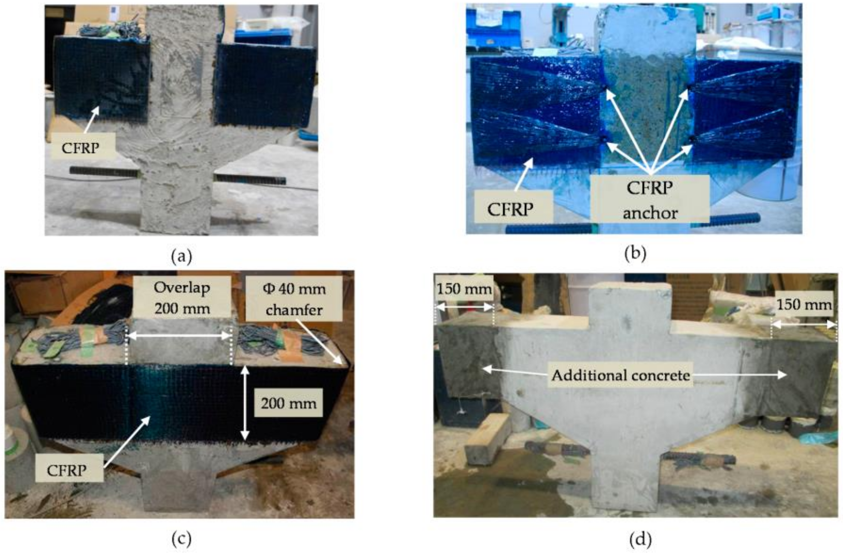
2.3. Application of CFRP

The CFRP tow sheet was laid based on wet lay-up as per manufacture’s guidelines. The step by step procedure to apply CFRP is explained below.
  • The bonding area was scrapped using a disk sander to completely remove the outer bleeding layer and crumbling surface or dirt, revealing the tough aggregates. All four sharp edges were rounded approximately 20 mm in radius. Tentative reference for rounding radius was taken from Sadeghian et al. 2010 [12]. Surface and voids were made free of grind dust using a high pressure air blower.
  • Prescribed proportion of primer (FP-NS) was mixed by hand and applied at room temperature over the roughened dry surface, as per manufacturer’s guidelines, at the rate of 200 g/m2. It was allowed to set hard for a minimum of three hours at the room temperature.
  • Levelling putty (FE-Z) was applied at the rate of 1500 g/m2 to smoothen uneven surfaces and sharp corners. All voids were filled properly with putty. It was allowed to set hard for a minimum of 24 h at room temperature.
  • The CFRP tow sheet was laid after applying one layer resin (FP-E3P) at the rate of 500 g/m2. Another cover layer resin was also applied at the same rate and rolled with a roller so that the resin connected to each fiber properly. For multiple layers of CRFP tow sheet, a layer of resin was applied below and above the sheet.
  • The test was performed seven days after the complete application of CFRP.

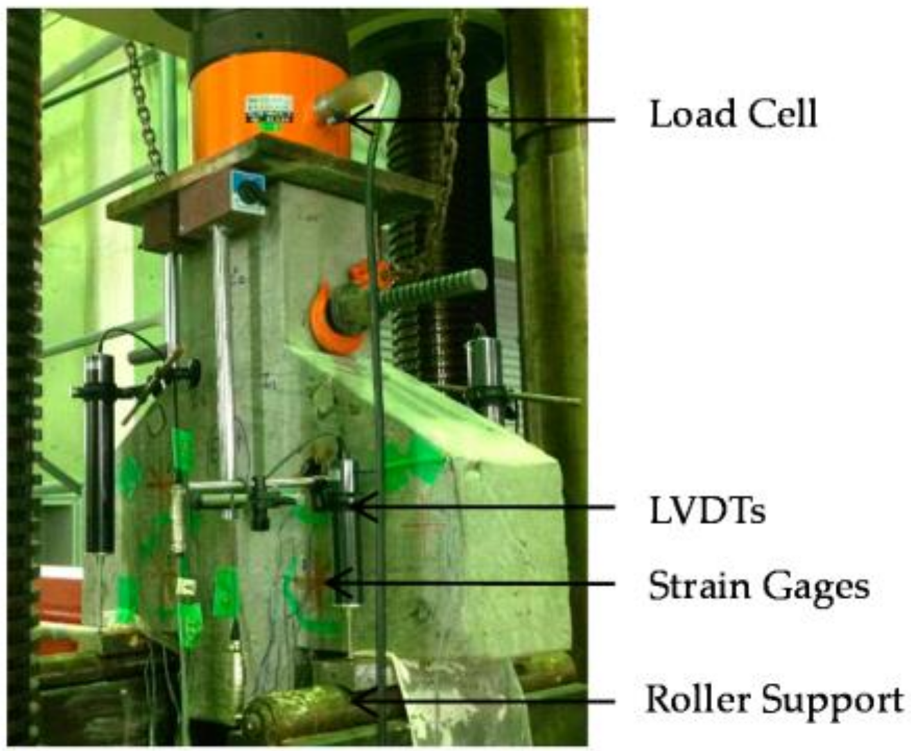
2.4. Test Setup and Measurements

The test was done by placing the inverted corbel on the UTM as shown in Figure 5. Load was applied at two symmetrically designed pad by moving the base vertically upward by controlling displacement at the constant rate of 0.0084 mm/s. Relative displacement of the load bearing pad at all four points was measured with respect to opposite (top) edge of column by using Linear voltage differential transforms (LVDTs). Total load at the top edge of the column was measured by using a load cell. In all cases, strains in main tension bars, concrete, and CFRP were measured using strain gages.

3. Experimental Results

3.1. Premature Failure and Residual Capacity

The main objective of the first series of the experiment was to verify whether the bearing pad positioned at the edge of the corbel represents similar behavior as the field observation or not. The load-displacement relationships for the first series of the experiment are shown in Figure 6. Maximum loads are included in Table 3. The load was defined as the total load measured at the top end of the column, while the displacement was calculated based on the relative displacement between the top end pad and main bearing pads. The compressive strength of the concrete shown in Table 1 was tested on the same day of corbel testing to ensure that the interpretation of load-displacement behavior was not affected by the variation in physical properties of concrete.
Experimental results show that by shifting the bearing pad at the edge of the corbel (PE-C), the loading capacity is significantly reduced by 46.5% compared to D-C. The reduction in the loading capacity in corbel occurs as the shear span to depth ratio increases.
The fracture patterns for the first series are shown in Figure 7. In both D-C and PE-C, the flexural cracks occurred initially at column-corbel interface (1). As the displacement was increased in D-C, the flexural compression failure occurred due to the appearance and localization of cracks at the compression strut (2) after the main flexural steel bars yielded as shown in Figure 7a. Meanwhile, in PE-C, secondary cracks were opened at the compression strut (2), but the final failure was brittle and the cracks opened outwards (3) before the main flexural steel bars yielded, as shown in Figure 7b. The observed cracks were similar to those corbels observed in the field (Figure 1). As PE-C showed the same cracking pattern and load-displacement behavior in the scope the local failure criterion as the field corbels, PE-C was taken as the control specimen in the retrofitting series.
Since failure in PE-C occurred before the yielding of the main reinforcement, the residual capacity of the corbel might not have dropped significantly, but there could be some reduction in capacity if loss in the bond between concrete and reinforcing bar occurred. Locally failed PE-C was reloaded by moving the bearing pad to the designed position that is the same as D-C. This specimen was designated ResCap-PE-C. The load-displacement relationship in ResCap-PE-C is included in Figure 6. The residual capacity in PE-C is almost 95.5% of that in D-C. The residual capacity of the damaged corbel is still very large if the bearing pad is moved to the designed position in accordance to the codes. New diagonal cracks propagating from the position of the new bearing pad to the sloping end of the corbel occurred, as shown by black lines (4) in Figure 7c. The residual capacity is intact. Hence, further retrofitting study was done on uncracked PE-C corbels for simplicity.

3.2. Retrofitting of Corbels Subjected to Local Failure Criterion

The purpose of the experimental investigation on the retrofitting approach adopted for corbel subjected to local failure criterion was to study the effectiveness of different retrofitting methods applied on the corbel with the pad at the edge (PE-C). The retrofitted specimen aimed to recover its capacity to the level of the corbel designed and detailed according to the codes (D-C), even though the pad was located at the edge. Figure 8 shows the load-displacement relationships for the retrofitting series in the experiment, while Figure 9 shows the fracture patterns for all retrofitting series in the experiment. Maximum loads at failure are included in Table 3.
Different behaviors were observed with different retrofitting methods. The load-displacement relationships show that the application of two layers of CFRP wrap terminating at the column face (CFRP-CF-2L) was able to improve the capacity in PE-C only by 61.44%. Despite the thickness and number of layer of CFRP being detailed according to ACI-440 [10] by limiting the strain, CFRP-CF-2L underwent early plate end delamination, resulting in the poor response shown in Figure 9a. The capacity was greatly improved when the CFRP wrap was anchored using fiber anchor at the column-corbel interface (CFRP-CF-2L(A)). The capacity in CFRP-CF-2L(A) recovered to 81% of capacity of D-C. Cracks along the compression strut in CFRP-CF-2L(A) developed more compared with those in CFRP-CF-2L, as shown in Figure 9b. Furthermore, the same number of layers of CFRP applied with full wrap (CFRP-FW-2L) showed much higher capacity improvement. The capacity in CFRP-FW-2L recovered to 92.02% of capacity of D-C, while the capacity in CFRP-FW-1L (1 layer CFRP full wrap) recovered to 76% of capacity of D-C. The main reason for the higher capacity in full wrap cases was the absence of the early delamination. CFRP was not fully strained in full wrap cases. Hence, the failure of the specimens was governed by the cracks of the compression strut, as shown in Figure 9c,d.
In RCJ-150 (RC jacketing), the capacity improvement is lower than in CFRP-FW-1L, which is only 73%. Since the anchorage length inside the column is shorter than that required by the design code [1], the reinforcing bars may not be anchored enough inside the column, which may affect the capacity in RCJ-150. Because of the difficulties in the experiment, a parametric study using 3D FEA was conducted to investigate the effect of the anchorage length inside the column. The results are discussed in Section 4.3.2. Figure 9e shows the concrete cover splitting above the post-installed reinforcement. Cracks occur equally at the column-corbel interface and compression strut. No cracks occurred at the joint between the old and new concrete. Among five specimens in the retrofitting series, the retrofitting method that could strengthen both in shear and flexural strength would be ideally effective on overall performance of the corbel. CFRP terminated at the column-corbel interface only makes partial contribution to the flexural compression. Therefore, poor performance is resulted.
Strains in CFRP and main flexural bars are shown in Figure 10, which helps to explain the behavior of CFRP on the corbel. The strains in the main flexural steel bar as shown in Figure 10a were measured at the location where the bearing pad in D-C was located, 125 mm from the face of the column. Meanwhile, Figure 10b shows the maximum strains measured in CFRP. In CFRP-CF-2L and CFRP-FW-1L, the maximum strain was measured at the position where the localized cracks occurred which is at the edge of the corbel, while in CFRP-FW-2L, the maximum strain was measured at the middle span of the corbel. PE-C failed when the strain in the main flexural bars was lower than D-C indicating the premature failure. In CFRP cases, the flexural strength was shared between the main flexural bars and CFRP. Horizontal unidirectional CFRP strap shows the improvement in the compression strut capacity.

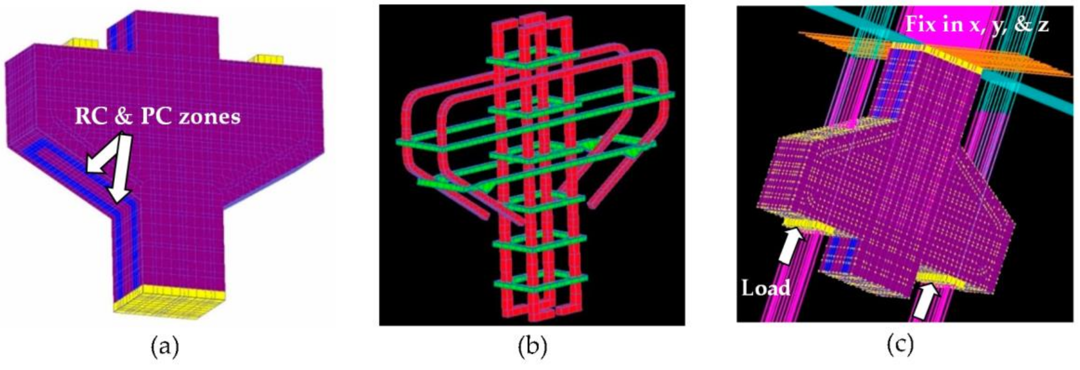
4. Numerical Analysis

4.1. Introduction and Constitutive Model

Non-linear 3D finite element analysis was carried out using commercial software called COM3D. The elasto-plastic and fracture (EPF) model was used to model the behavior of concrete before cracking occurs. The model idealizes uncracked concrete as combining plasticity and continuum fracture, which represents the permanent deformation and loss of elastic strain energy absorption, respectively [13]. Considering the bond transfer between concrete and steel elements, the concept of three dimensional zoning was implemented such that the fracture energy of concrete element far from the steel bar was reduced as compared to that of concrete element adjacent to bar. It is expressed in the post-cracking concrete tension model and commonly known as C-parameter in COM3D. C-parameter is a parameter describing the inclination of descending envelope curve and the cracking strain of concrete in tension. After conducting sensitivity analysis and based on its relationship with the element size, average value of C-parameter was taken as 1.10 and 0.40 for plain concrete element away for steel bar and concrete element adjacent to the steel bar, respectively.
Finite element mesh size of 15 mm was generated as shown in Figure 11a. The reinforcing bars were modeled as steel elements, while concrete was modeled as concrete elements. CFRP was modeled as steel elements having the same thickness as the specified fiber thickness. Perfect bond model was adopted between CFRP and concrete because no bond failure was observed in the experiment. CFRP sheets were peeled off manually after the experiment and thin layer of concrete was seen on the attached CFRP surface indicating no bond failure. Figure 11a also shows the geometry of the numerical models. All models’ dimensions were the same as those in the experimental specimens. The reinforcement arrangements in the numerical models matched those of the experimental specimens as shown in Figure 11b. For the simplicity of the model, the round shape of the reinforcement in the experiment was modeled as the rectangular shape. The material properties of the reinforcement in each model were the same as those of the experimental specimens. Figure 11c shows the boundary conditions of the numerical models. Fixed condition in all directions was assumed at the top edge of the column. Monotonic displacement-loading was applied to the bearing pads of the corbel. Displacement-controlled load was applied in 48 steps with 0.08 mm increments at each step.

4.2. Validation of Experimental Works

Numerical model was established for all specimens. The numerical results are expressed in terms of load-displacement relationships and principal strain contours. The load-displacement relationships for the first series of the numerical results are shown in Figure 6, while the load-displacement relationships for the second and third series of the numerical results are shown in Figure 8a,b, respectively. The maximum loads for the numerical results are included in Table 3. The load-displacement relationships of the numerical results are compared with those of the experimental results. The maximum loads calculated by the numerical results are in-line with those observed in the experimental results, with discrepancies of 9–21%. Although the numerical results overestimate the experimental loads with the average of 14.13%, the maximum loads observed in the experiment were reasonably simulated. The capacity in D-C is higher than that in PE-C. Meanwhile, the maximum load in CFRP-FW-2L is the highest among all cases in the second series, while the maximum load of CFRP-CF-2L is the smallest among all cases in the second series. The tension softening parameter taken in the simulation is the reason for such differences as discussed by Neupane et al. [14] by conducting the simulation of the tension softening parameter sensitivity. Figure 12 shows the principal strain contours in the simulation results for all cases. The principal strain contours in the simulation show a good match with the observed fracture patterns in the experiment.
In D-C, the formation of compression strut was predicted, while in P-E, the local fracture was simulated well. Furthermore, the plate end debonding in CFRP-CF-2L and the flexural and compression cracks in RCJ-150 predicted in the simulation matched those observed in the experiment. In CFRP-FW-2L, simulation result showed that local strain concentration is prevented. The proposed mechanisms in the previous section are clarified through the study of the simulation results. Even though significant improvement in the loading capacity is reported in both the experimental and numerical studies, none of the retrofitting methods was enough to recommend a useful solution. Hence, further study was continued based on the parametric studies using numerical simulation.

4.3. Parametric Studies

4.3.1. Higher CFRP Stiffness and Lower Tensile Strength in CFRP-FW-2L

CFRP used in experimental series were of higher tensile strength (3.45 GPa) and lower modulus of elasticity (245 GPa). CFRP with higher modulus of elasticity (540 GPa) is available on the market, but with lower ultimate tensile strength (1.9 GPa) and a thickness of 0.13 mm. In order to have a good comparison, the thickness of CFRP modeled in the simulation was 0.5 mm, which is equivalent to a two layer thickness of 0.25 mm CFRP used in experiment. The study was intended to study of the sensitivity of tensile strength and modulus of elasticity of CFRP. The load-displacement relationships are shown in Figure 13. Based on load displacement relationships of the simulation results, the modulus of elasticity of CFRP is a more important parameter than the tensile strength. The simulation results showed that CFRP with a 0.5 mm thickness is effective to recover the designed strength of the corbel by keeping the position of the pad at the edge. However, CFRP with a higher modulus of elasticity is only available on very thin sheets of 0.13 mm. Therefore, four layers of CFRP with a 0.13 mm thickness should be applied. For higher number of layer of CFRP, confinement may not be increased geometrically. Experimental study is recommended for the case with multiple layer of CFRP.

4.3.2. Flexibility of Application Range of RC Jacketing

The difficulty in the application of RC jacketing over corbel was experienced. If the additional concrete block can be reinforced with steel bars anchored well inside the confinement zone of the column, its effectiveness will be increased more. Hence, a simple numerical study was carried out to investigate the effectiveness of RCJ-150 if the steel bars can be inserted 50 mm inside the column on the both sides of the corbel so that stress at the end of the bar can be transferred to the steel bars in the column. Other parameters were kept the same. Figure 14 shows the load-displacement relationship where the steel bars are inserted 30 mm and 50 mm inside the column. Based on the simulation results, due to the adequate anchorage of new steel bars inside the corbel, the capacity is fully recovered to D-C level which is 39% higher than the previous case where the steel bars are inserted 30 mm inside the column. However, 50 mm is not taken as guideline, since stress transfer varies per specimen size, but the reinforcement is anchored inside the confined portion of column.

5. Conclusions

In order to investigate the structural strengthening of reinforced concrete corbels subjected to local failure using external FRP wrapping, three experimental series consisting of eight RC corbel specimens and an extended numerical study on RC corbels were conducted. Furthermore, parametric studies using numerical simulation were done in order to investigate and recommend a retrofitting method where the loading capacity can be fully recovered to the level of the corbel designed and detailed according to the codes. The following conclusions can be drawn:
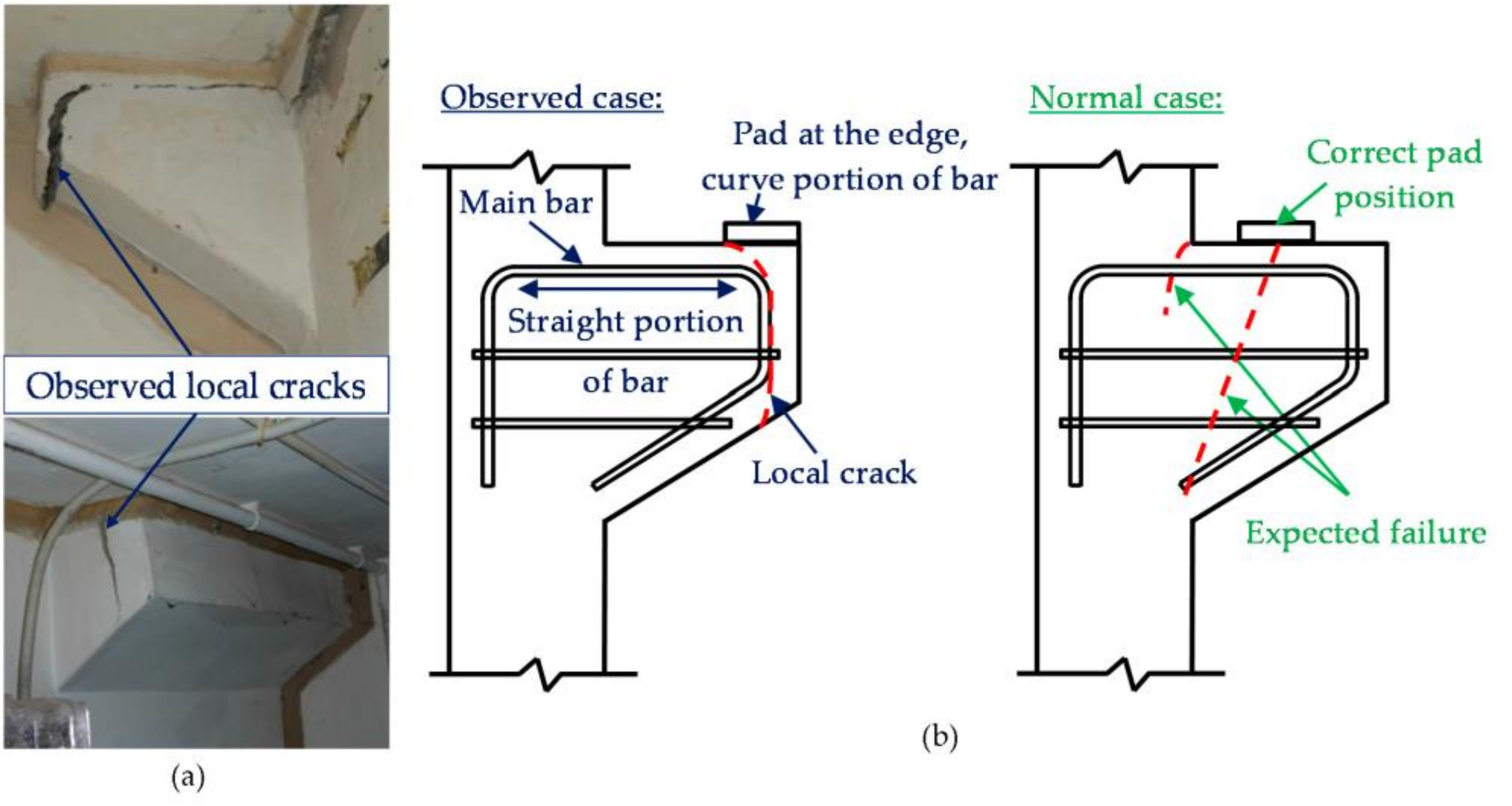
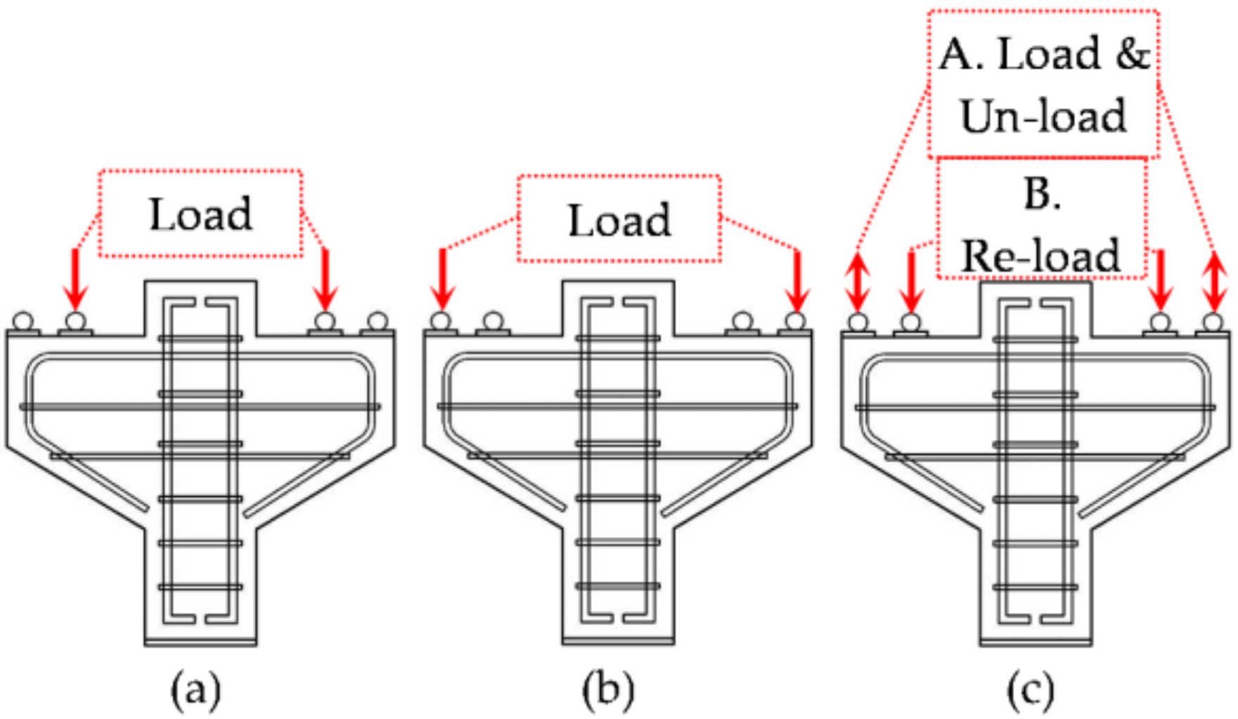
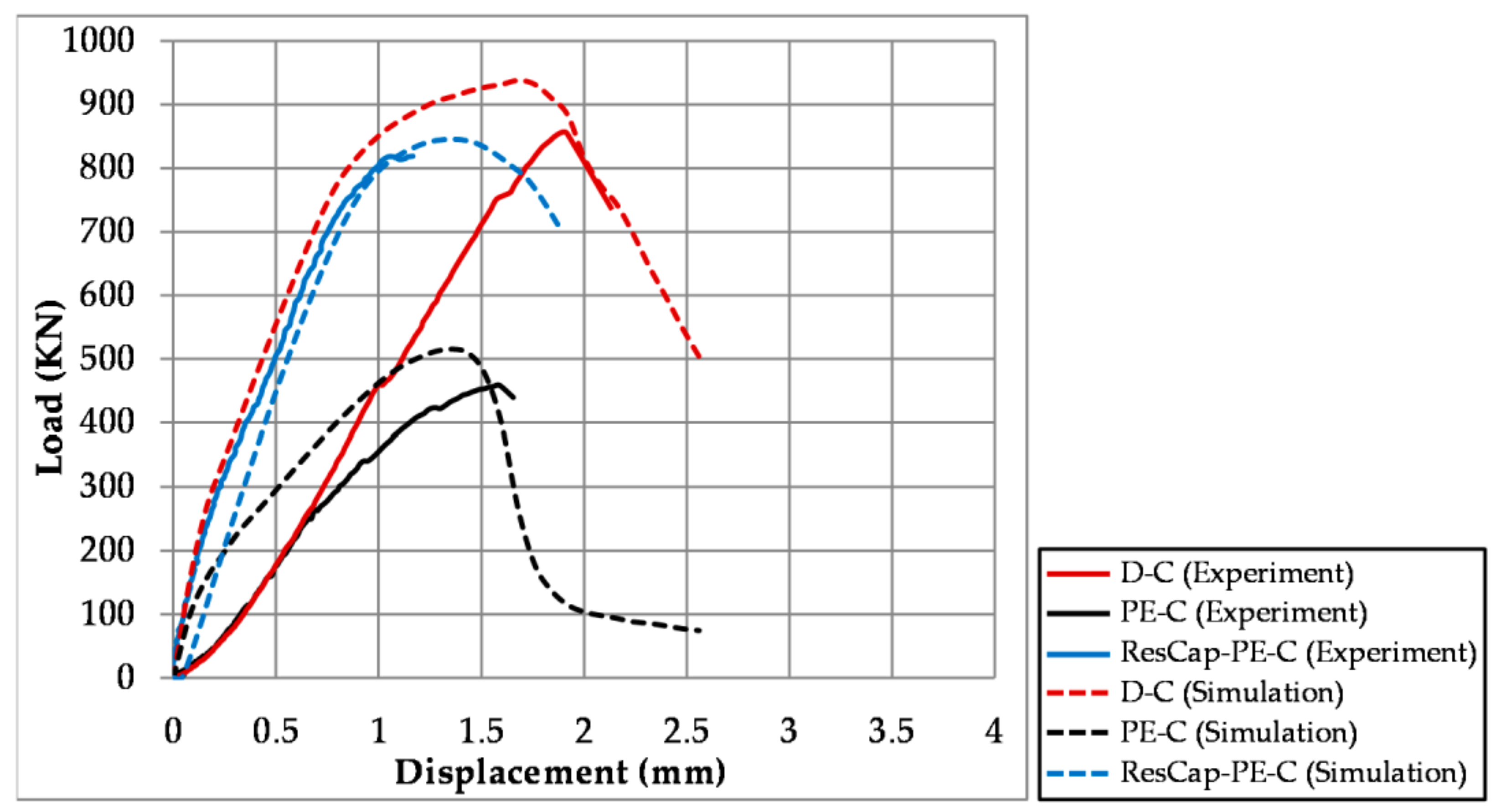
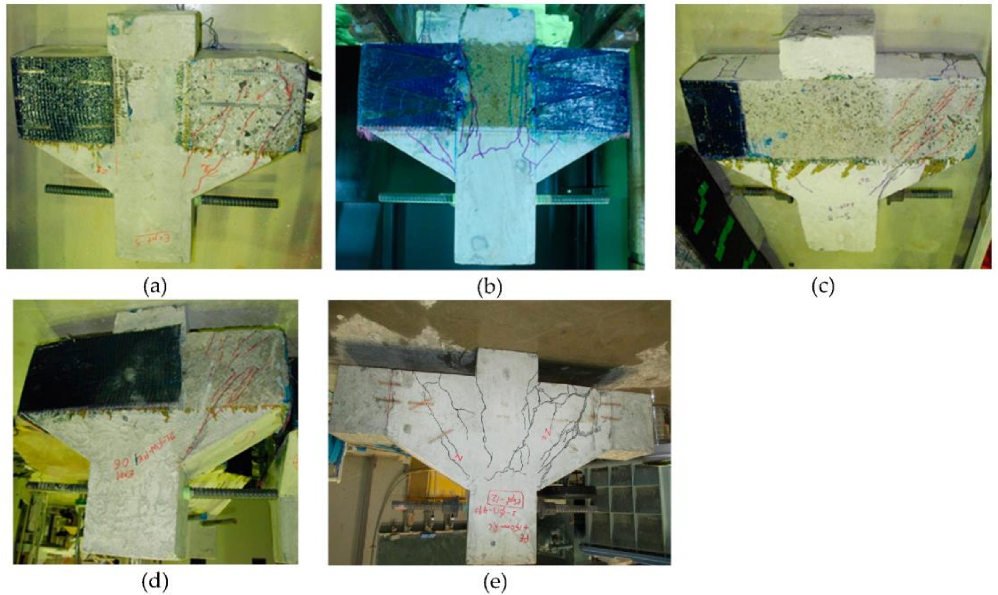
  • It was confirmed through the experimental observation and numerical simulation that the wrong position of bearing pad (PE-C) where the bearing pad is placed at the edge of the RC corbel causes a significant drop in the loading capacity due to of local splitting failure. It was observed in the experiment that the capacity of the corbel was reduced by 46.5%, while in the simulation, it was predicted that the capacity was reduced by 46.1%. In order to investigate the residual capacity of the damaged corbel, the locally failed PE-C was reloaded by moving the bearing pad to the designed position. Residual capacity of the damaged corbel (ResCap-PE-C) was almost 95.5% of the corbel designed and detailed according to the codes (D-C).
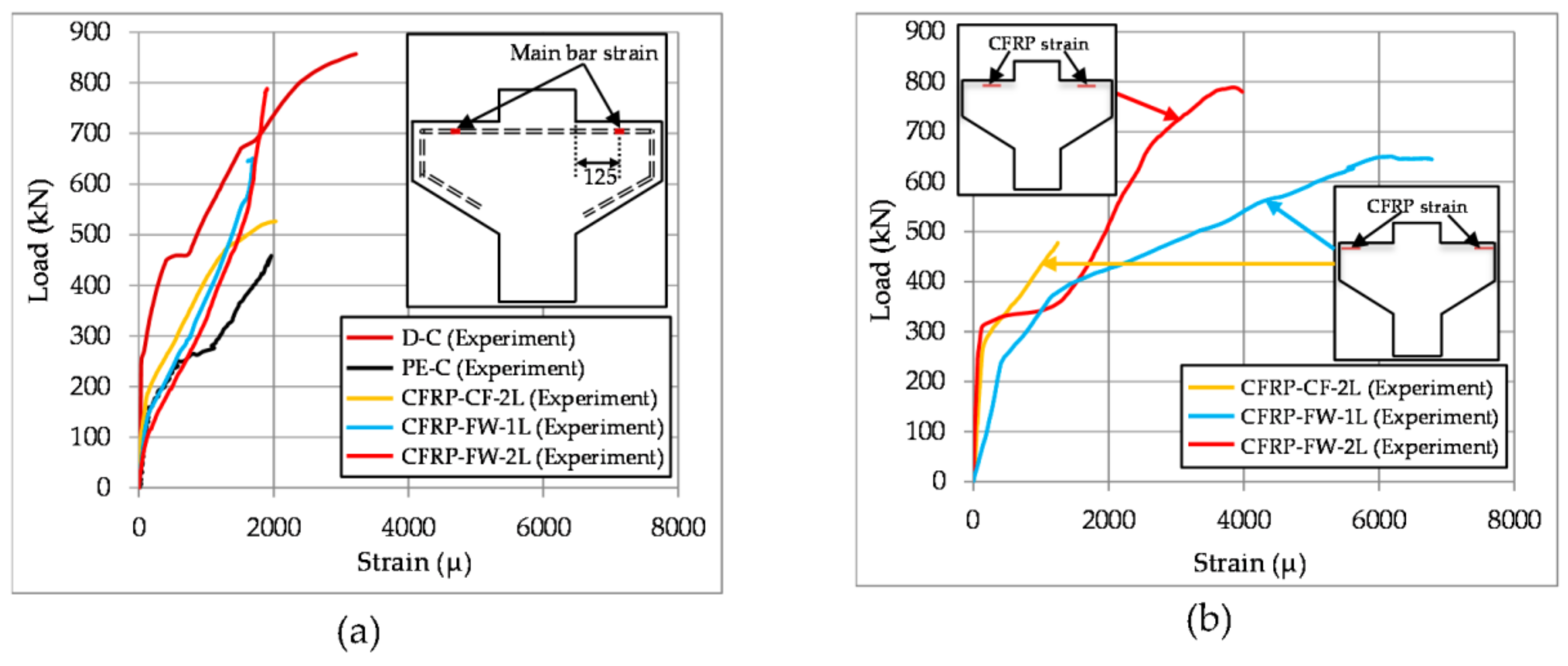
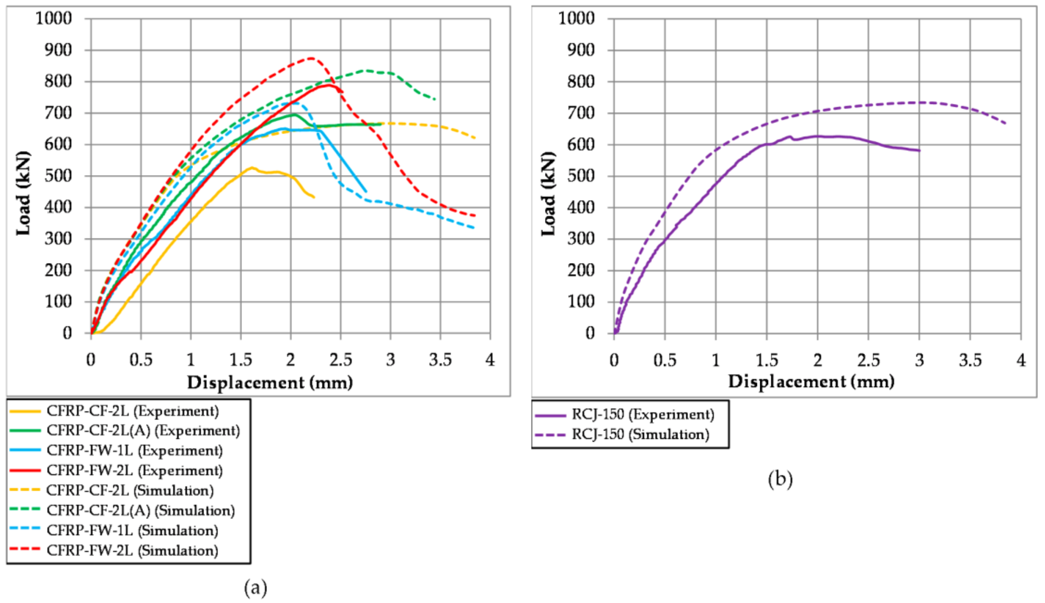
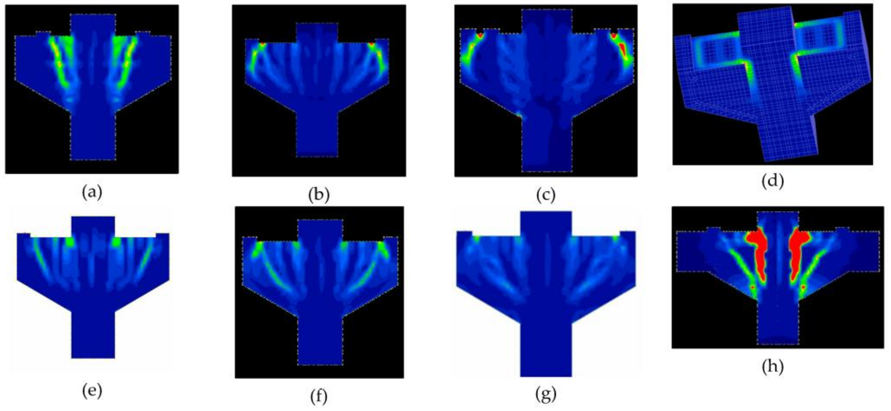
  • Different retrofitting methods show different behaviors in terms of loading capacity and failure behavior. CFRP full wrap case (CFRP-FW-2L) was more effective than CFRP wrap terminated at the column face cases (CFRP-CF-2L and CFRP-CF-2L(A)). CFRP-FW-2L showed a 92.02% capacity improvement, while CFRP-CF-2L and CFFRP-CF-2L(A) showed 61.44% and 81% capacity improvements, respectively. The main reason was the absence of the early delamination of CFRP in CFRP-FW-2L. Meanwhile, the retrofitting method using CFRP wrap was superior to RC jacketing because of the occurrence of concrete cover splitting above the post-installed steel bars. The capacity improvement in RCJ-150 was 73%. The same tendencies were predicted by the numerical simulation. However, none of the retrofitting methods could fully recover the capacity of the corbel to the capacity level of the corbel designed and detailed according to codes (DC).
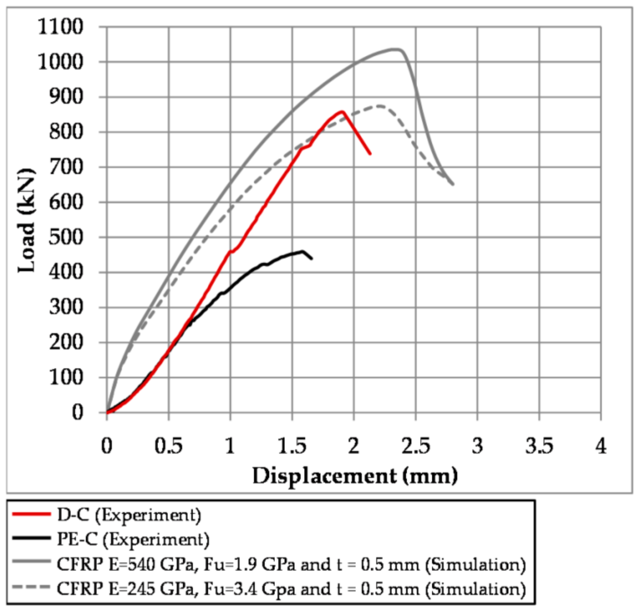
  • Based on the parametric studies using numerical simulation, the modulus of elasticity of CFRP had higher influence than its ultimate tensile strength. It is recommended that if the initial stiffness and the ultimate tensile strength of CFRP are 540,000 MPa and 1900 MPa, respectively, four layers of CFRP, 0.13 mm in thickness, are effective to recover the designed strength of the corbel.
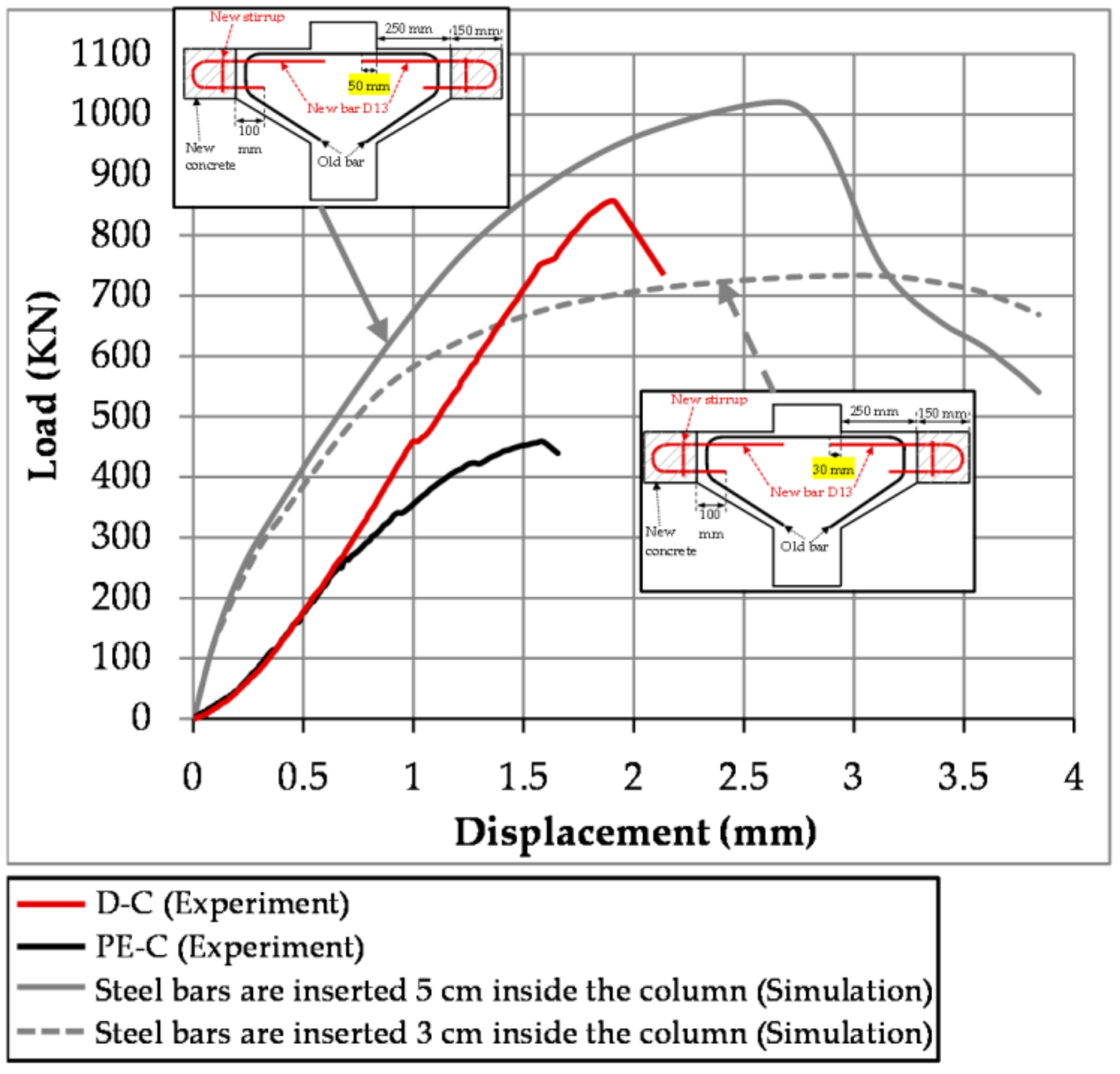
  • Numerical simulation showed that RC jacketing is a more flexible method for retrofitting the damaged corbel because increasing the reinforcement ratio or anchorage length has a direct influence on its loading capacity. Inadequate anchorage of the inserted reinforcing bars will reduce the strengthening ability for the corbel-column interface.

Acknowledgments

All CFRP tow sheets, primer, and epoxy used to carry out this research were provided by Nippon Steel & Sumikin Materials Co. Ltd., Chiyoda-ku, Japan. The authors acknowledge Arazoe from Nippon Steel & Sumikin Materials Co. Ltd. for the guidance, physical help, and expertise provided during the application of CFRP.

Author Contributions

Kohei Nagai and Ram Chandra Neupane conceived and designed the experiments; Ram Chandra Neupane and Liyanto Eddy performed the experiments; Kohei Nagai, Ram Chandra Neupane and Liyanto Eddy analyzed the data and wrote the paper.

Conflicts of Interest

The authors declare no conflict of interest.

References

  1. ACI (American Concrete Institute). Building Code Requirements for Structural Concrete; ACI 318-11; American Concrete Institute: Farmington Hills, MI, USA, 2011. [Google Scholar]
  2. CEN. Eurocode 2: Design of Concrete Structures-Part 1-1: General Rules and Rules for Buildings. EN1992-1-1. Comité Europeen de Normalisation: Brussels, Belgium, 2004. Available online: https://law.resource.org/pub/eu/eurocode/en.1992.1.1.2004.pdf (accessed on 7 April 2017).
  3. Kriz, L.B.; Raths, C.H. Connections in Precast Concrete Structures: Strength of Corbels. J. PCA Res. Dev. Lab. 1965, 10, 16–61. [Google Scholar] [CrossRef]
  4. Limam, O.; Foret, G.; Ehrlacher, A. RC Two-ways Slabs Strengthened with CFRP Strips: Experimental Study and A Limit Analysis Approach. Compos. Struct. 2003, 60, 467–471. [Google Scholar] [CrossRef]
  5. Wang, Z.; Wang, D.; Smith, S.T.; Lu, D. CFRP-Confined Square RC Columns. I: Experimental Investigation. J. Compos. Constr. 2012, 16, 150–160. [Google Scholar] [CrossRef]
  6. Zhang, Z.; Hsu, C.T.; Moren, J. Shear Strengthening of Reinforced Concrete Deep Beams Using Carbon Fiber Reinforced Polymer Laminates. J. Compos. Constr. 2004, 8, 403–414. [Google Scholar] [CrossRef]
  7. Campione, G.; La Mendola, L.; Papia, M. Flexural Behavior of Concrete Corbels Containing Steel Fibers or Wrapped with FRP Sheets. Mater. Struct. 2005, 38, 617–625. [Google Scholar] [CrossRef]
  8. Elgwady, M.A.; Rabie, M.; Mostafa, M.T. Strengthening of Corbels Using CFRP an Experimental Program. Cairo University: Giza, Egypt, 2005. Available online: http://www.quakewrap.com/frp%20papers/Strengthening-Of-Corbels-Using-CFRP-An-Experimental-Program.pdf (accessed on 7 April 2017).
  9. Shadhan, K.K.; Kadhim, M.M. Use of CFRP laminates for strengthening of reinforced concrete corbels. Int. J. Civ. Eng. Technol. 2015, 6, 11–20. [Google Scholar]
  10. ACI (American Concrete Institute). Guide for the Design and Construction of Externally Bonded FRP Systems for Strengthening Concrete Structures; ACI 440.2R-08; American Concrete Institute: Farmington Hills, MI, USA, 2008. [Google Scholar]
  11. Kalfat, R.; Al-Mahaidi, R.; Smith, S.T. Anchorage Devices Used to Improve the Performance of Reinforced Concrete Beams Retrofitted with CFRP Composites: State-of-the-art Review. J. Compos. Constr. 2013, 17, 14–33. [Google Scholar] [CrossRef]
  12. Sadeghian, P.; Rahai, A.R.; Ehsani, M.R. Experimental Study of Rectangular RC Columns Strengthened with CFRP Composites under Eccentric Loading. J. Compos. Constr. 2010, 14, 443–450. [Google Scholar] [CrossRef]
  13. Maekawa, K.; Pimanmas, A.; Okamura, H. Nonlinear Mechanics of Reinforced Concrete, 1st ed.; Spon Press: London, UK; New York, NY, USA, 2003. [Google Scholar]
  14. Neupane, R.C.; Nagai, K.; Eddy, L. Governing Parameters of Various Strengthening Approaches Applied for RC Corbels Subjected to Local Failure Criterion. In Proceedings of the 1st International Conference on Infrastructure Failure and Consequences, Melbourne, Australia, 16–18 July 2014. [Google Scholar]
Figure 1. (a) Field observed premature corbel failure case; (b) failure pattern illustration.
Fibers 05 00016 g001
Figure 2. Specimen dimension and rebar details (units: mm).
Fibers 05 00016 g002
Figure 3. Experimental specimens in the first series: (a) D-C, (b) PE-C, and (c) ResCap-PE-C.
Fibers 05 00016 g003
Figure 4. Experimental specimens in the second and third series: (a) CFRP-CF-2L; (b) CFRP-CF-2L(A); (c) CFRP-FW-1L and CFRP-FW-2L; (d) RCJ-150.
Fibers 05 00016 g004
Figure 5. Test setup and measurements.
Fibers 05 00016 g005
Figure 6. Load-displacement relationships for corbels of the first series.
Fibers 05 00016 g006
Figure 7. Fracture patterns for corbels of the first series: (a) D-C, (b) PE-C, and (c) ResCap-PE-C.
Fibers 05 00016 g007
Figure 8. Load-displacement relationships for corbels of the retrofitting series: (a) CFRP series and (b) Reinforced concrete (RC) jacketing series.
Fibers 05 00016 g008
Figure 9. Fracture patterns for corbels of the retrofitting series: (a) CFRP-CF-2L; (b) CFRP-CF-2L(A); (c) CFRP-FW-1L; (d) CFRP-FW-2L; (e) RCJ-150.
Fibers 05 00016 g009
Figure 10. Load-strain relationships: (a) Main flexural steel bar and (b) CFRP surface.
Fibers 05 00016 g010
Figure 11. Details of numerical model: (a) 3D FE mesh model; (b) Reinforcement arrangement; and (c) Boundary conditions.
Fibers 05 00016 g011
Figure 12. Principle strain contours in the simulation: (a) D-C; (b) PE-C; (c) ResCap-PE-C; (d) CFRP-CF-2L; (e) CFRP-CF-2L(A); (f) CFRP-FW-1L; (g) CFRP-FW-2L; and (h) RCJ-150.
Fibers 05 00016 g012
Figure 13. Load-displacement relationships for parametric study of CFRP stiffness.
Fibers 05 00016 g013
Figure 14. Load-displacement relationships for parametric study of the effect of the rebar anchorage length inside the corbel.
Fibers 05 00016 g014
Table 1. Details of test series and specimens.
SeriesSpecimen NumberSpecimen NameParameterShear Span av (mm)Comp. Strength of Concrete f’c (MPa)
Series 11D-CBearing pad at the middle of the corbel12546.59
2PE-CBearing pad at the edge of the corbel22045.52
3ResCap-PE-CResidual capacity12545.52
Series 24CFRP-CF-2L2 layers CFRP wrap terminated at the column face22046.77
5CFRP-CF-2L(A)2 layers CFRP wrap terminated at the column face with fiber anchor22048.26
6CFRP-FW-1L1 layer CFRP full wrap with 200 mm overlay22042.49
7CFRP-FW-2L2 layers CFRP full wrap with 200 mm overlay22043.15
Series 38RCJ-150RC jacketing22047.52
Table 2. Material properties of the reinforcement and carbon fiber–reinforced polymer (CFRP).
MaterialModulus of Elasticity
Es or EFRP (MPa)
Yield Strength
fy (MPa)
Ultimite Strength
FFRP,u (MPa)
Steel bar D10190,000390-
Steel bar D13 and D16190,000490-
CFRP245,000-3400
Table 3. Maximum loads for corbels of all specimens.
CaseMaximum Load (kN)
ExperimentSimulation
D-C857.0938.1
PE-C458.4515.4
ResCap-PE-C818.9845.1
CFRP-CF-2L526.6667.5
CFRP-CF-2L(A)694.5834.5
CFRP-FW-1L650.5730.9
CFRP-FW-2L788.7872.1
RCJ-150626.5733.8

