Indirect Tensile Behaviour of Fibre Reinforced Alkali-Activated Composites


1
CONSTRUCT, Faculty of Engineering (FEUP), University of Porto, 4200-465 Porto, Portugal
2
ISISE, Department of Civil Engineering, University of Minho, 4800-058 Guimarães, Portugal
3
Department of Engineering, University of Trás-os-Montes e Alto Douro, 5001-801 Vila Real, Portugal
*
Author to whom correspondence should be addressed.
Fibers 2018, 6(2), 30; https://doi.org/10.3390/fib6020030
Submission received: 19 February 2018
/
Revised: 26 March 2018
/
Accepted: 12 April 2018
/
Published: 14 May 2018
(This article belongs to the Special Issue Geopolymer Based Fiber Reinforced Composites)
Abstract
:There are currently still some sustainability-related issues that need to be tackled within the construction sector. Namely, cement production is accountable for nearby 5% of the worldwide total CO2-eq release. Therefore, environmentally viable and economically sustainable solutions need to be pursued in order to mitigate the use of Portland cement. The incorporation of industrial waste in concrete compositions, such as fly ash (from coal combustion in power stations) is a feasible alternative. The properties of these residues may be enhanced through alkaline activation, which is able to yield aluminosilicate-based materials with excellent physico-chemical properties. Nonetheless, these materials exhibit a brittle behaviour. Therefore, the present work addresses the study of alkali-activated composites reinforced with sisal fibres. For that purpose, alkali-activated Class F fly ash was mixed with natural fibres and the composite mechanical behaviour was assessed through both indirect tensile and compressive tests. Four different fibre contents, in wt % of fly ash (0, 0.2, 0.6 and 1%), two fibre lengths (13 and 50 mm) and four curing periods (14, 28, 56 and 112 days) were considered. Results confirm that the post-cracking response of these composites was improved with the inclusion of sisal fibres. In general, higher residual tensile strengths and dissipated energy were observed for the lengthier fibres, i.e., 50 mm.
1. Introduction
It is widely acknowledged that, nowadays, a strong commitment should be embraced to develop more sustainable materials for the construction industry. At the present time, concrete is the leading construction material as well as the second most consumed substance on Earth, only after water. Moreover, the production of Portland cement has a relevant environmental impact, as the production of a ton of cement requires about 4 GJ energy and releases about 1 ton of CO2 into the atmosphere. Portland cement is itself responsible for about 5% of the global production of CO2 [1]. Considering the current and forthcoming European legislation within the framework of waste valorization, which arises from the necessity of finding solutions that could protect the environment and the well-being of the population, the challenge previously mentioned is a priority and the margin to postpone the introduction of these materials on the market begins to be short.
Probably one of the major challenges, if not the greatest considering its wide use, is to find binder materials that could compete with Portland cement. Nowadays, it is recognized that alkaline activation is a valid process to produce alternative binders using industrial by-products as raw material. This chemical process, which implies the existence of a precursor rich in aluminosilicates and an alkaline activator (e.g., sodium hydroxide or sodium silicate), consists in the conversion of glassy structures into cementitious composites [2]. Several investigations have studied the behaviour of alkali-activated fly ash. One of the most relevant properties mentioned is the considerable mechanical performance that these materials present, in which curing conditions play a key role [2,3,4,5]. Even though there is a wide range of applications, alkali-activated fly ash has been used mainly in experiments to evaluate the performance of mortars and concretes manufactured with this binder. The results in terms of strengths are promising [6,7,8,9], but there is still an aspect that deserves attention: namely, its brittle behaviour, similar to Portland cement-based matrices. At present, manifold types of discrete fibres from distinct materials, different geometries and configurations are employed to reinforce cementitious matrices. In general, depending on the fibre type and content, a multiplicity of distinct composites with enhanced post-cracking behaviour, energy absorption capacity, crack width restraint and even functionally graded performance can be obtained, by e.g., [10,11,12,13,14]. In addition, pushed by sustainability requisites, the use of renewable bio-based fibres, by e.g., hemp, flax, sisal [15,16] and just, is increasing. Even though the performance of bio-based fibres are comparable to the ones of glass fibres [17] in terms of stiffness and cost, in terms of strength still have a slight underperformance. Nonetheless, bio-based fibres are becoming a more and more feasible solution.
This work aimed to evaluate the effect of sisal fibre reinforcement on the mechanical behaviour of alkali-activated fly ash. To achieve this goal, uniaxial compressive strength tests and indirect (splitting) tensile tests were conducted at different curing periods (14, 28, 56 and 112 days). Two fibre lengths (13 and 50 mm) and three different fibre contents by weight of fly ash were used (0.2, 0.6 and 1.0%). The results were compared with unreinforced control mixtures.
2. Materials and Methods
2.1. Composition and Materials Characterisation
A Portuguese thermo-electric power plant provided the fly ash, FA, used in this study. Based on the silica, alumina and iron content (Table 1), as well on the recommendations of the ASTM C 618 [18] standard, the fly ash was classified as Class F. The chemical composition was obtained by X-ray fluorescence analysis (XRF) on a BRUKER® S8 TIGER WDXRF X-ray spectrometer (BRUKER, Madrid, Spain).
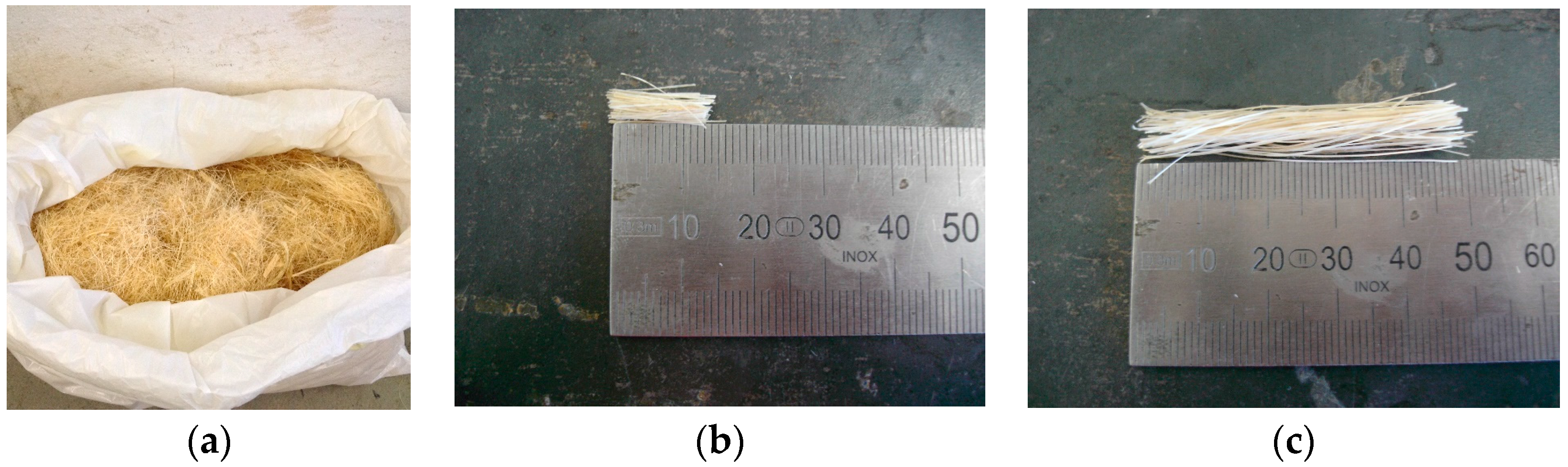
Figure 1 shows the sisal fibres used in the experimental campaign. The sisal fibres had a specific weight of 750–1070 kg/m3 and a diameter ranging between 0.080 and 0.300 mm. Their tensile strength and elongation at rupture were of 230 MPa and 2.08–4.18%, respectively (cf. [19]). The adopted fibre lengths (lf) were approximately 13 and 50 mm.
The fly ash was activated with an alkaline solution (L) containing sodium hydroxide and sodium silicate (with a hydroxide to silicate weight ratio, SH/SS, of 2). The sodium hydroxide, with a specific gravity of 2.13 at 20 °C (99 wt·%), was supplied in pellets and dissolved in distilled water, to attain a 12.5 molar solution. The sodium silicate solution had a unit weight of 1.464 g/cm3 at 20 °C. The SiO2/Na2O ratio was 2.0 (molar oxide ratio of 2.063) and the Na2O concentration in the solution was 13.0%.
2.2. Specimen Production
Two different types of specimens were prepared in this experimental work. The uniaxial compression strength tests were carried out on cylindrical specimens with a diameter of 70 mm and height of 140 mm, while the indirect tensile tests were performed on cylindrical specimens with a diameter and height of 150 and 60 mm, respectively.
The specimens used for both the compressive and indirect tensile tests were prepared with three different fibre contents (Cf): 0.2, 0.6 and 1.0% by weight of fly ash. Control specimens, without fibre reinforcement, were also manufactured for each of the two test types. All the tests were performed at four distinct ages: namely, 14, 28, 56 and 112 days. Table 2 includes the adopted nomenclature for the studied mixtures.
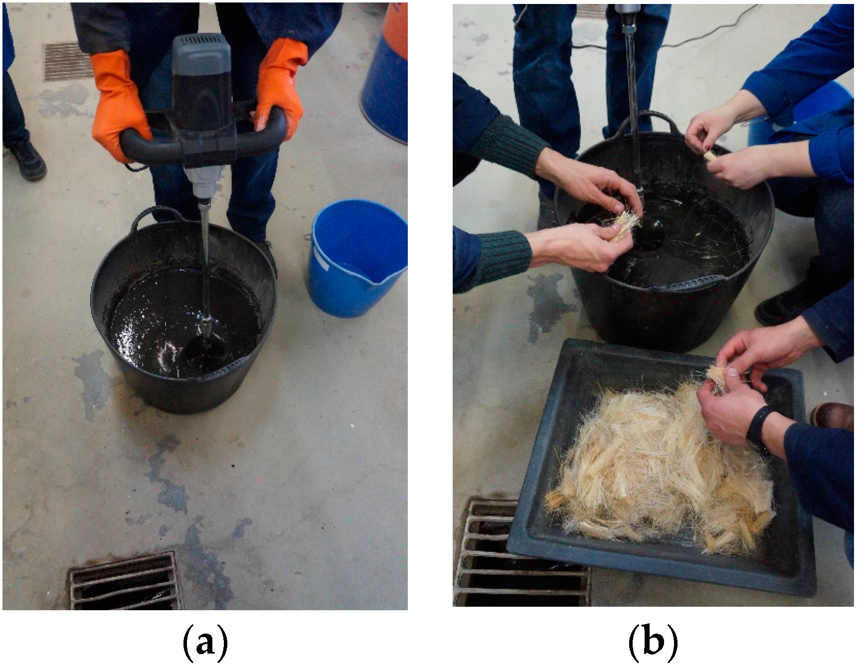
The components of the mixtures were added to a container according to the following sequence: fly ash, activator, and finally fibres. The homogenization of the mixtures was accomplished by using a portable electric hand-held mixing drill. In the reinforced mixtures, the fibres were slowly added to the mixture in order to improve their dispersion.
The total mixing time was five minutes. Figure 2 shows pictures of the manufacture of the test specimens. Due to the high alkaline solution/fly ash ratio (i.e., 0.70), the mixtures exhibited a good workability and fluidity, and therefore no kind of external compaction/vibration was needed to cast the specimens.
The specimens were cured at room ambient temperature and humidity. Every specimen was demoulded and wrapped in cling film one week after its manufacture. Afterwards, the specimens were stored back in the same conditions until the day of their respective test (14, 28, 56 or 112 days).
In order to localise fracture, in particular on the fibre reinforced specimens, all specimens were notched. Two notches were performed on the top and bottom surfaces of the cylindrical specimens with a depth and width of 5 mm. The introduction of the notch favours the appearance of a single crack leading to a better estimation of the post-cracking tensile behaviour of the reinforced specimens [20].
2.3. Uniaxial Compression Test
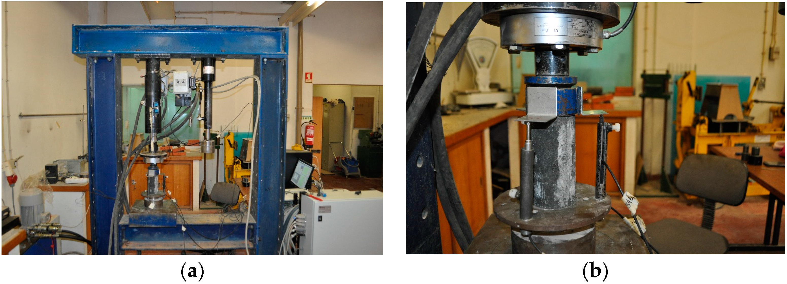
The uniaxial compressive strength (UCS) was assessed in accordance with ASTM D2166-16 [21], on a servo-hydraulic testing rig, fitted with a 200 kN load cell (Figure 3). The relative displacement of the loading plates was obtained by the average readings of three linear variable differential transformers (LVDTs), which were fixed around the test sample and formed an angle of 120° between consecutive LVDTs.
Tests were carried out under displacement control at a constant rate of 0.5 mm/min. Prior to testing, all specimens were weighted and measured and stress-strain curves were computed having into account each specimen’s exact dimensions. For the compressive tests, only one specimen per each series was tested.
2.4. Splitting Tensile Test
The indirect tensile (IT) tests (Figure 4) were prepared and carried out by adapting the recommendations of the ASTM C496M standard [22]. The servo-hydraulic testing rig previously used was now fitted with a 10 kN load cell. The crack mouth opening displacement (CMOD) was determined based on the readings performed by five LVDTs (3 on the specimen’s top surface and 2 on the bottom surface).
The setup of the test began with the installation, on the specimen’s surface, of the supporting structures for the LVDTs, in a direction perpendicular to the notch, i.e., to the theoretical fracture plane. The specimen was placed between two steel hemi-cylinders installed on opposite generatrices, maintaining the notch plane aligned with the load actuator axis. Finally, the LVDTs were installed on the specimen’s surface.
The tests were performed under displacement control with a constant rate of 0.4 mm/min. The three specimens tested for each series were previously weighed and measured and the stress–CMOD curves were calculated for each specimen.
3. Results and Discussion
3.1. Uniaxial Compression Tests
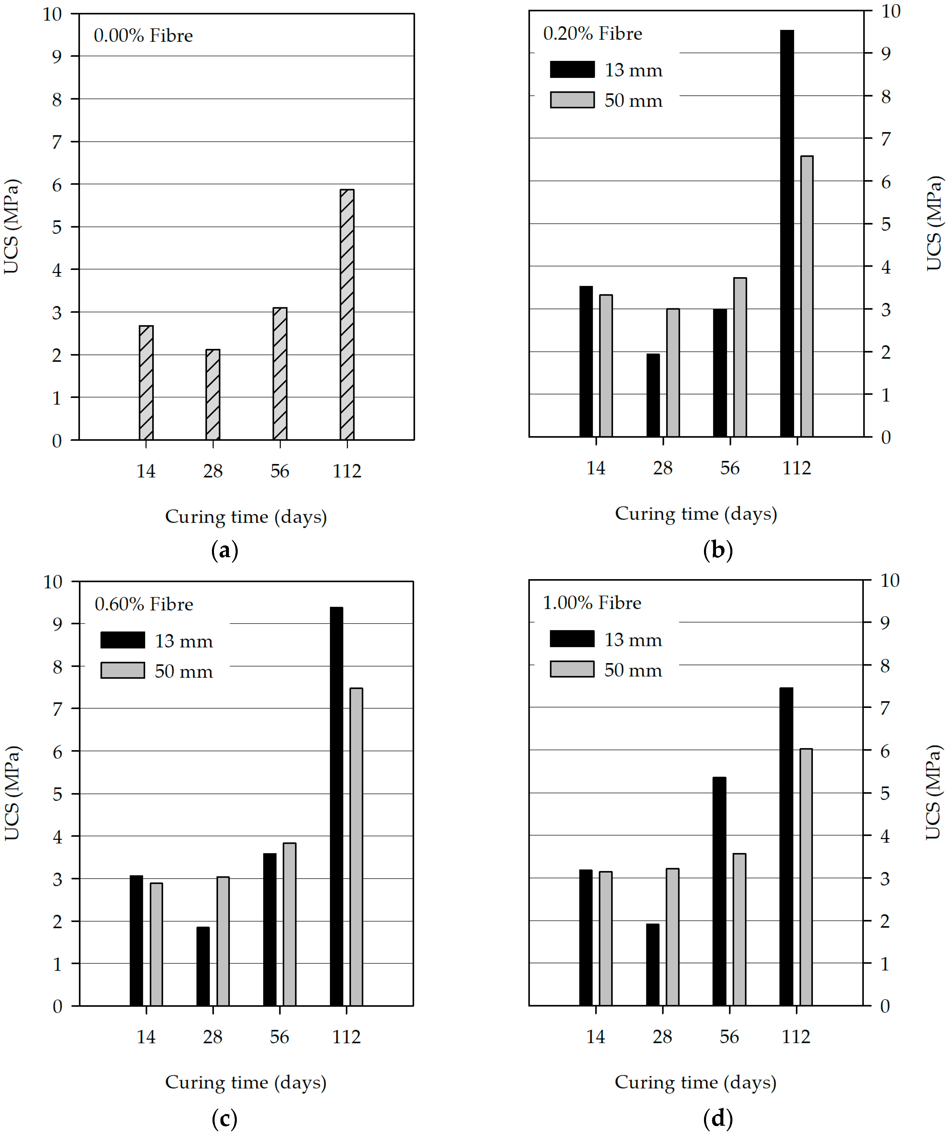
Figure 5 shows the variation of the compressive strength with the curing time. The compressive strength improved, in general, with the curing time; however, for some series, a strength decrease was observed from 14 to 28 days. Moreover, in general, the incorporation of fibres increased the compressive strength when compared with control mixtures (UC) regardless of the length (13 and 50 mm) and the fibre content (0.2%, 0.6% and 1.0%). In particular, this strength increment was more visible for the series with fibres of 13 mm tested at 112 days. Nonetheless, the scatter of the results regarding the different curing periods was high. In addition, the strength values obtained for the fibre reinforced series with a curing period up to 56 days were nearer the values obtained for the corresponding unreinforced series. The strength increase with fibres was only not observed in 4 out of the 12 series, respectively, regarding the mixtures that comprised fibres with a length of 13 mm.
The compressive strengths of the mixtures, at 28 days, UA.1b (1.93 MPa), UA.2b (1.84 MPa) and UA.3b (1.91 MPa), with fibre contents of 0.2%, 0.6% and 1.0%, respectively, were lower than the control mixture (2.12 MPa). The same behaviour was observed at 56 days for the mixture which was prepared with a fibre content of 0.2% (UA.1c), which exhibited a strength of 2.99 MPa, lower than the value attained by the control mixture (3.10 MPa).
The highest strength values were, as expected, observed at 112 days. In pastes composed by alkali-activated materials with a low calcium content, which is the case for the fly ash used in this work, the resulting product is a N-A-S-H gel-like material in which the strength increases with longer curing periods [23]. In the present work, this increase was more meaningful for specimens reinforced with 13 mm fibres with a content of 0.2% and 0.6%. In the latter, a strength increase of approximately 3 times at 112 days was observed when compared to the values achieved at 14 days. In particular, an increase from 3.52 MPa (UA.1a) to 9.53 MPa (UA.1d) for the mixtures with a fibre content of 0.2% and from 3.06 MPa (UA.2a) to 9.38 MPa (UA.2d) for their counterparts with a fibre content of 0.6% was observed. The strengths of the mixtures with fibre contents of 0.2% and 0.6%, but with a fibre length of 50 mm, are not so high, 6.58 MPa (UB.1d) and 7.48 MPa (UB.2d), respectively. Considering the series reinforced with 0.2% and 0.6% tested at 28 and 56 days, it can be stated that higher strengths were achieved when it was used lengthier fibres.
Respecting the mixtures with fibre contents of 0.2% and 0.6%, it is observed that the strengths are nearly similar at 14 and 56 days to both fibre lengths. However, and considering a fibre length of 13 mm, a decrease in strength from 3.52 MPa (UA.1a) to 2.99 MPa (UA.1c) occurs in the mixtures with a fibre content of 0.2%, while in the mixtures with a fibre content of 0.6%, there is an increase in the strength from 3.06 MPa (UA.2a) to 3.58 MPa (UA.2c).
The level of the strength values achieved at 112 days for the mixtures with a fibre content of 1.0% was not as high as those with different fibre contents (7.46 MPa (UA.3d) and 6.02 MPa (UB.3d), respectively, for mixtures that were prepared with fibres of 13 and 50 mm), which suggests that the increase in the fibre content does not generate such a positive effect on the compressive strength of this type of alkali-activated system. Except for the results with regard to a curing period of 28 days, it was found that the mixtures with fibres of 13 mm and a content of 1.0% obtained lower strengths.
One last aspect that deserves attention is related to the strength decrease from 14 to 28 days that occurred in all mixtures, which is related to the behaviour of the matrix constituted by the alkali-activated fly ash. During an experimental campaign that aimed to study the chemical stability of mortars made of sand and alkali-activated metakaolin, which is also a low calcium material similar to fly ash, Palomo et al. [24] witnessed advancements and setbacks in the mechanical behaviour of the studied mixtures. Between 7 and 28 days the strengths decreased, between 28 and 56 days a recovery of those strengths was observed, between 56 and 90 days the strengths decreased again, and after that period a continuous growth was observed until 270 days. It is important to note that, during that period, due to the aim of the work, the samples stayed immersed in solutions; a circumstance that must be considered when the results are analysed. Moreover, Lloyd [25] also observed a similar behaviour in metakaolin-based geopolymer mortars. In this case, the compression strength increased until 28 days, between 28 and 90 days it decreased, which was then followed by a progressive growth of the strength until 180 days.
As previously shown, the fluctuation of mechanical strengths of alkali-activated systems in which the precursor is a low calcium material is a frequent circumstance that is not yet fully understood.
3.2. Indirect Tensile Tests
3.2.1. Tensile Splitting Strength
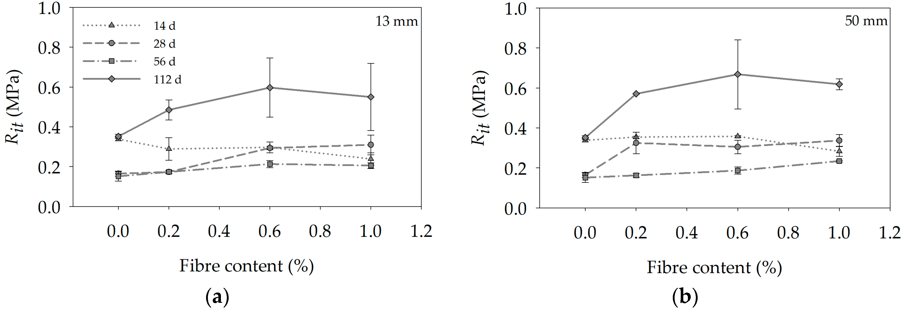
Figure 6 depicts the evolution of the tensile splitting strength (Rit) with the fibre content, for the series prepared with 13 and 50 mm fibres.
The indirect tensile splitting strength (Rit) was calculated through the following equation:
where F is the peak load and D and H are, respectively, the diameter and height of the specimens.
The results show that, in general, the indirect tensile strength increased with the fibre content with the exception of the series regarding the 14 days, in which the increase of fibre content favoured a decrease of the indirect tensile strength. In Figure 6, there are a few error bars that are not noticeable. This circumstance is justified by the very low scatter of the results observed for some of the studied series.
For the series with fibres of 13 mm, the highest tensile strength was attained for a 0.6% fibre content. For a fibre content of 0.6%, when the results are compared with the control mixtures, the more meaningful differences regarding strength improvements are observed for a curing period of 28 days. In this case, the improvement was approximately 80% (IA.2c and ICc mixtures achieved strengths of 0.29 MPa and 0.16 MPa, respectively). Within the framework of this comparison, the increase of approximately 70% for a curing period of 112 days cannot be ignored (IA.2d and ICd mixtures attained strengths of 0.35 MPa and 0.60 MPa, respectively). The differences of the strength values at 112 days and the remaining curing periods are very significant. These results are related with the strength and compactness of the matrix established by the activated ash, which were previously discussed.
Regarding the obtained results for the mixtures with fibres of 50 mm, similar trends were observed to the ones previously discussed for the series with 13 mm fibres. Moreover, there is an aspect that should be highlighted: with the exception of the series tested at 56 days, the tensile strengths were higher than the corresponding series with fibres of 13 mm. At 112 days, where the highest strengths were observed, the tensile strength increase varies between 12% (IB.2d = 0.67 MPa) and 18% (IB.1d = 0.57 MPa) for mixtures with fibre contents of 0.6 and 0.2%, respectively. Considering this observation, the fibres with 50 mm lead to higher tensile strength. At 28 and 56 days, the strengths are higher when the fibre content is 1.0% (0.34 MPa and 0.23 MPa for mixtures IB.3b and IB.3c, respectively). On the other hand, at 14 and 112 days, the maximum strengths were reached when a fibre content of 0.6% is used (0.36 MPa and 0.67 MPa for mixtures IB.2a and IB.2d, respectively). In summary, for mixtures with the highest tensile strengths, respectively, tested at 112 days, a fibre content of 0.6% led to the highest tensile results.
3.2.2. Stress–CMOD Curves
Figure 7 shows the stress–crack mouth opening width (σ–CMOD) average curves of the specimens tested at a curing period of 28 days. In general, two types of tensile behaviour were observed. First, for the series with a fibre length of 50 mm, reinforced with the highest fibre contents, i.e., 0.6% and 1.0%, after the localization of the macro-crack there is a slight strength decrease that is then followed by a pseudo-hardening branch up to a CMOD smaller than 1.0 mm. Afterwards, a softening behaviour was observed up to the end of the indirect tensile test. On the other hand, for the remaining series, after the peak stress is attained, corresponding to the localization of the macro-crack, a softening behaviour is observed. Therefore, the 50 mm fibres were able to transfer higher bridging residual stresses over the crack surfaces, consequently leading to higher dissipated energies.
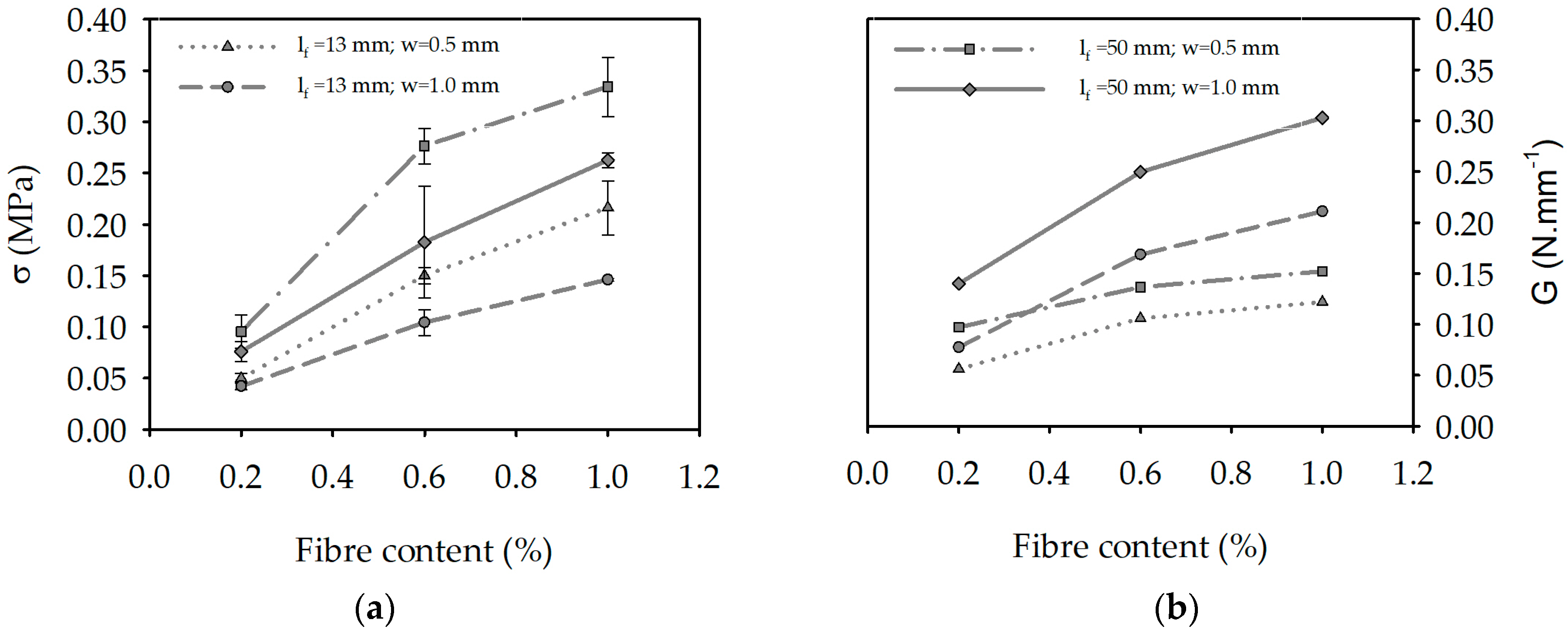
3.2.3. Residual Stresses and Dissipated Energies
Figure 8 shows, for mixtures with a curing period of 28 days, the variation of the residual stresses and dissipated energies with the fibre content for a crack width of 0.5 and 1.0 mm. The dissipated energy was computed from the area under the stress–crack mouth opening curve. It was observed that both the post-cracking stress and dissipated energy increased with the fibre content, regardless of the crack width (0.5 or 1.0 mm) and the fibre length (13 or 50 mm).
Regarding the residual stresses, the highest values were observed for the series with 50 mm fibres and the highest fibre content, i.e., 1.0%. Therefore, the higher the fibre content, the higher the capability of the matrix to maintain higher residual tensile stresses, even until appreciable crack widths. The dissipated energy also increased with the fibre content. The toughness was higher when fibres of 50 mm were used. In summary, the fibres with 50 mm length were more effective on enhancing the post-cracking behaviour of the used alkali-activated matrices.
4. Conclusions
In this work, the compressive and indirect tensile behaviour of alkali-activated fly ash was assessed and discussed. The influence of the curing time, fibre length and content on the composite’s mechanical behaviour was evaluated.
In general, the compressive strength increased with the curing time. However, a strength decrease from 14 to 28 days occurred in all mixtures, which could be related to the behaviour of the matrix constituted by the alkali-activated fly ash. This strength reduction was also observed by other researchers. The addition of sisal fibres to alkali-activated fly ash compositions improved both the compressive and tensile strengths. Nonetheless, the inclusion of sisal fibres had a higher impact on the improvement of the post-cracking behaviour, in particular on the ductility and post-cracking strengths of these reinforced composites. Fibres with a 50 mm length were more effective in increasing the residual tensile strength as well as the dissipated energy. Considering the results obtained in terms of the tensile strengths, namely, the lower values observed at 28 and 56 days for some of the series in comparison to the results attained at 14 days, it is reasonable to suggest carrying out further experimental campaigns in order to better understand the influence of adding sisal fibres to alkali-activated systems. These investigations will also be an important tool to help clarify the results observed in this work.
Author Contributions
F.A. wrote the article and analysed the experimental results. V.M.C.F.C. and N.C. conceived and designed the experimental campaign, as well contributed to the manuscript revision; T.M. contributed to the manuscript revision.
Conflicts of Interest
The authors declare no conflict of interest.
References
- Worrel, E.; Price, L.; Martin, N.; Hendriks, C.; Meida, L. Carbon dioxide emissions from the global cement industry. Annu. Rev. Energy Environ. 2001, 26, 303–329. [Google Scholar] [CrossRef]
- Palomo, A.; Grutzeck, M.; Blanco, M. Alkali-activated fly ashes: A cement for the future. Cem. Concr. Res. 1999, 29, 1323–1329. [Google Scholar] [CrossRef]
- Fernández-Jiménez, A.; Palomo, A. Composition and microstructure of alkali activated fly ash binder: Effect of the activator. Cem. Concr. Res. 2005, 35, 1984–1992. [Google Scholar] [CrossRef]
- Criado, M.; Palomo, A.; Fernández-Jiménez, A. Alkali activation of fly ashes. Part 1: Effect of curing conditions on the carbonation of the reaction products. Fuel 2005, 84, 2048–2054. [Google Scholar] [CrossRef]
- Provis, J.L. Alkali-activated materials. Cem. Concr. Res. 2017. [Google Scholar] [CrossRef]
- Williamson, T.; Juenger, M. The role of activating solution concentration on alkali–silica reaction in alkali-activated fly ash concrete. Cem. Concr. Res. 2016, 83, 124–130. [Google Scholar] [CrossRef]
- Singh, B.; Ishwarya, G.; Gupta, M.; Bhattacharyya, S. Geopolymer concrete: A review of some recent developments. Constr. Build. Mater. 2015, 85, 78–90. [Google Scholar] [CrossRef]
- Ryu, G.; Lee, Y.; Koh, K.; Chung, Y. The mechanical properties of fly ash-based geopolymer concrete with alkaline activators. Constr. Build. Mater. 2013, 47, 409–418. [Google Scholar] [CrossRef]
- Ferreira, L.; Costa, H.; Barata, I.; Júlio, E.; Tiago, P.; Coelho, J. Precast alkali-activated concrete towards sustainable construction. Mag. Concr. Res. 2014, 66, 618–626. [Google Scholar] [CrossRef]
- Barros, J.A.O.; Cunha, V.M.C.F.; Ribeiro, A.F.; Antunes, J.A.B. Post-Cracking Behaviour of Steel Fibre Reinforced Concrete. Mater. Struct. 2005, 38, 47–56. [Google Scholar] [CrossRef]
- Bentur, A.; Mindess, S. Fibre Reinforced Cementitious Composites, 2nd ed.; CRC Press: Boca Raton, FL, USA, 2006; p. 624. ISBN 9780415250481. [Google Scholar]
- American Concrete Institute. State-of-the-Art Report on Fiber Reinforced Concrete; Technical Report ACI 544.1R-96; American Concrete Institute: Farmington Hills, MI, USA, 2009. [Google Scholar]
- Pereira, E.B.; Fischer, G.; Barros, J.A.O. Effect of hybrid fiber reinforcement on the cracking process in fiber reinforced cementitious composites. Cem. Concr. Compos. 2012, 34, 1114–1123. [Google Scholar] [CrossRef]
- Shen, B.; Hubler, M.; Paulino, G.H.; Struble, L.J. Functionally-graded fiber-reinforced cement composite: Processing, microstructure, and properties. Cem. Concr. Compos. 2008, 30, 663–673. [Google Scholar] [CrossRef]
- Tolêdo Filho, R.D.; Scrivener, K.; England, G.; Ghavami, K. Durability of alkali-sensitive sisal and coconut fibres in cement mortar composites. Cem. Concr. Compos. 2000, 22, 127–143. [Google Scholar] [CrossRef]
- Savastano, H.; Warden, P.G.; Coutts, R.S.P. Brazilian waste fibres as reinforcement for cement-based composites. Cem. Concr. Compos. 2000, 22, 379–384. [Google Scholar] [CrossRef]
- Pickering, K.L.; Efendy, M.G.A.; Le, T.M. A review of recent developments in natural fibre composites and their mechanical performance. Compos. Part A Appl. Sci. Manuf. 2016, 83, 98–112. [Google Scholar] [CrossRef] [Green Version]
- ASTM International. Standard Specification for Coal Fly Ash and Raw or Calcined Natural Pozzolan for Use in Concrete; ASTM C618-15; ASTM International: West Conshohocken, PA, USA, 2015. [Google Scholar]
- Tolêdo Filho, R.D. Materiais Compósitos Reforçados com Fibras Naturais: Caracterização Experimental [Composite Materials Reinforced with Natural Fibres: Experimental Characterization]. Ph.D. Thesis, Pontifical Catholic University of Rio de Janeiro, Rio de Janeiro, Brazil, 1997. [Google Scholar]
- Abrishambaf, A.; Barros, J.A.O.; Cunha, V.M.C.F. Tensile stress–crack width law for steel fibre reinforced self-compacting concrete obtained from indirect (splitting) tensile tests. Cem. Concr. Compos. 2015, 57, 153–165. [Google Scholar] [CrossRef] [Green Version]
- ASTM International. Standard Test Method for Unconfined Compressive Strength of Cohesive Soil; ASTM D2166/D2166M-16; ASTM International: West Conshohocken, PA, USA, 2016. [Google Scholar]
- ASTM International. Standard Test Method for Splitting Tensile Strength of Cylindrical Concrete Specimens; ASTM C496/C496M-04; ASTM International: West Conshohocken, PA, USA, 2004. [Google Scholar]
- Palomo, A.; Krivenko, P.; García-Lodeiro, I.; Kavalerova, E.; Maltseva, O.; Fernández-Jiménez, A. A review on alkaline activation: New analytical perspectives. Mater. Constr. 2014, 64. [Google Scholar] [CrossRef]
- Palomo, A.; Blanco-Varela, M.T.; Granizo, M.L.; Puertas, F.; Vazquez, T.; Grutzeck, M.W. Chemical stability of cementitious materials based on metakaolin. Cem. Concr. Res. 1999, 29, 997–1004. [Google Scholar] [CrossRef]
- Lloyd, R. Accelerated ageing of geopolymers. In Geopolymers—Structure, Processing, Properties and Industrial Applications; Provis, J., Deventer, J., Eds.; Woodhead Publishing Limited: Cambridge, UK, 2009; pp. 139–166. ISBN 978-1-84569-449-4. [Google Scholar]
Figure 1.
Sisal fibres: (a) general view; (b) fibres with 13 mm; (c) fibres with 50 mm.

Figure 2.
Manufacture of the test specimens: (a) mixing; (b) addition of the fibres.

Figure 3.
Uniaxial compressive strength (UCS) test set-up: (a) general view; (b) test in progress.

Figure 4.
Splitting tensile tests: (a) placement of the linear variable differential transformers (LVDTs); (b) test in progress.
Figure 4.
Splitting tensile tests: (a) placement of the linear variable differential transformers (LVDTs); (b) test in progress.

Figure 5.
Uniaxial compressive strength for a fibre content of (a) 0%, (b) 0.2%, (c) 0.6% and (d) 1.0%.
Figure 5.
Uniaxial compressive strength for a fibre content of (a) 0%, (b) 0.2%, (c) 0.6% and (d) 1.0%.

Figure 6.
Indirect tensile strength tests results for mixtures with (a) fibres of 13 mm; (b) fibres of 50 mm.
Figure 6.
Indirect tensile strength tests results for mixtures with (a) fibres of 13 mm; (b) fibres of 50 mm.

Figure 7.
Stress–crack width average curves of the specimens tested at 28 days: (a) mixtures with 13 mm fibres; (b) mixtures with 50 mm fibres.
Figure 7.
Stress–crack width average curves of the specimens tested at 28 days: (a) mixtures with 13 mm fibres; (b) mixtures with 50 mm fibres.

Figure 8.
Variation with the fibre content of (a) residual stresses and (b) dissipated energy.


Table 1.
Chemical composition of the fly ash (FA) (wt %).
| Element | FA |
|---|---|
| SiO2 | 55.27 |
| Al2O3 | 21.77 |
| Fe2O3 | 11.15 |
| CaO | 2.85 |
| K2O | 2.82 |
| TiO2 | 1.58 |
| MgO | 1.37 |
| Na2O | 0.93 |
| SO3 | 1.55 |
| P2O5 | 0.70 |
Table 2.
Identification and characterisation of the mixtures. L/FA: alkaline solution/fly ash; SH/SS: hydroxide to silicate weight ratio. a: 14 days; b: 28 days; c: 56 days; d: 112 days.
Table 2.
Identification and characterisation of the mixtures. L/FA: alkaline solution/fly ash; SH/SS: hydroxide to silicate weight ratio. a: 14 days; b: 28 days; c: 56 days; d: 112 days.
| Label | Cf [%] | lf [mm] | L/FA | SH/SS | Curing Days |
|---|---|---|---|---|---|
| UC (a/b/c/d) | 0 | — | 0.70 | 2 | 14 (a), 28 (b), 56 (c), 112 (d) |
| UA.1 (a/b/c/d) | 0.2 | 13 | 0.70 | 2 | 14 (a), 28 (b), 56 (c), 112 (d) |
| UA.2 (a/b/c/d) | 0.6 | 13 | 0.70 | 2 | 14 (a), 28 (b), 56 (c), 112 (d) |
| UA.3 (a/b/c/d) | 1.0 | 13 | 0.70 | 2 | 14 (a), 28 (b), 56 (c), 112 (d) |
| UB.1 (a/b/c/d) | 0.2 | 50 | 0.70 | 2 | 14 (a), 28 (b), 56 (c), 112 (d) |
| UB.2 (a/b/c/d) | 0.6 | 50 | 0.70 | 2 | 14 (a), 28 (b), 56 (c), 112 (d) |
| UB.3 (a/b/c/d) | 1.0 | 50 | 0.70 | 2 | 14 (a), 28 (b), 56 (c), 112 (d) |
| IC (a/b/c/d) | 0 | — | 0.70 | 2 | 14 (a), 28 (b), 56 (c), 112 (d) |
| IA.1 (a/b/c/d) | 0.2 | 13 | 0.70 | 2 | 14 (a), 28 (b), 56 (c), 112 (d) |
| IA.2 (a/b/c/d) | 0.6 | 13 | 0.70 | 2 | 14 (a), 28 (b), 56 (c), 112 (d) |
| IA.3 (a/b/c/d) | 1.0 | 13 | 0.70 | 2 | 14 (a), 28 (b), 56 (c), 112 (d) |
| IB.1 (a/b/c/d) | 0.2 | 50 | 0.70 | 2 | 14 (a), 28 (b), 56 (c), 112 (d) |
| IB.2 (a/b/c/d) | 0.6 | 50 | 0.70 | 2 | 14 (a), 28 (b), 56 (c), 112 (d) |
| IB.3 (a/b/c/d) | 1.0 | 50 | 0.70 | 2 | 14 (a), 28 (b), 56 (c), 112 (d) |
© 2018 by the authors. Licensee MDPI, Basel, Switzerland. This article is an open access article distributed under the terms and conditions of the Creative Commons Attribution (CC BY) license (http://creativecommons.org/licenses/by/4.0/).
Share and Cite
MDPI and ACS Style
Almeida, F.; Cunha, V.M.C.F.; Miranda, T.; Cristelo, N. Indirect Tensile Behaviour of Fibre Reinforced Alkali-Activated Composites. Fibers 2018, 6, 30. https://doi.org/10.3390/fib6020030
AMA Style
Almeida F, Cunha VMCF, Miranda T, Cristelo N. Indirect Tensile Behaviour of Fibre Reinforced Alkali-Activated Composites. Fibers. 2018; 6(2):30. https://doi.org/10.3390/fib6020030
Chicago/Turabian StyleAlmeida, Filipe, Vítor M. C. F. Cunha, Tiago Miranda, and Nuno Cristelo. 2018. "Indirect Tensile Behaviour of Fibre Reinforced Alkali-Activated Composites" Fibers 6, no. 2: 30. https://doi.org/10.3390/fib6020030
Note that from the first issue of 2016, this journal uses article numbers instead of page numbers. See further details here.